JP2012195687A - Transmitter, receiver, and communication system - Google Patents
Transmitter, receiver, and communication system Download PDFInfo
- Publication number
- JP2012195687A JP2012195687A JP2011056848A JP2011056848A JP2012195687A JP 2012195687 A JP2012195687 A JP 2012195687A JP 2011056848 A JP2011056848 A JP 2011056848A JP 2011056848 A JP2011056848 A JP 2011056848A JP 2012195687 A JP2012195687 A JP 2012195687A
- Authority
- JP
- Japan
- Prior art keywords
- frame
- marking
- received
- bits
- bit
- Prior art date
- Legal status (The legal status is an assumption and is not a legal conclusion. Google has not performed a legal analysis and makes no representation as to the accuracy of the status listed.)
- Pending
Links
Images


Classifications
-
- H—ELECTRICITY
- H04—ELECTRIC COMMUNICATION TECHNIQUE
- H04L—TRANSMISSION OF DIGITAL INFORMATION, e.g. TELEGRAPHIC COMMUNICATION
- H04L1/00—Arrangements for detecting or preventing errors in the information received
- H04L1/08—Arrangements for detecting or preventing errors in the information received by repeating transmission, e.g. Verdan system
-
- H—ELECTRICITY
- H04—ELECTRIC COMMUNICATION TECHNIQUE
- H04L—TRANSMISSION OF DIGITAL INFORMATION, e.g. TELEGRAPHIC COMMUNICATION
- H04L1/00—Arrangements for detecting or preventing errors in the information received
- H04L1/004—Arrangements for detecting or preventing errors in the information received by using forward error control
- H04L1/0056—Systems characterized by the type of code used
- H04L1/0061—Error detection codes
-
- H—ELECTRICITY
- H04—ELECTRIC COMMUNICATION TECHNIQUE
- H04L—TRANSMISSION OF DIGITAL INFORMATION, e.g. TELEGRAPHIC COMMUNICATION
- H04L1/00—Arrangements for detecting or preventing errors in the information received
- H04L1/0078—Avoidance of errors by organising the transmitted data in a format specifically designed to deal with errors, e.g. location
- H04L1/0083—Formatting with frames or packets; Protocol or part of protocol for error control
-
- H—ELECTRICITY
- H04—ELECTRIC COMMUNICATION TECHNIQUE
- H04L—TRANSMISSION OF DIGITAL INFORMATION, e.g. TELEGRAPHIC COMMUNICATION
- H04L1/00—Arrangements for detecting or preventing errors in the information received
- H04L1/12—Arrangements for detecting or preventing errors in the information received by using return channel
- H04L1/16—Arrangements for detecting or preventing errors in the information received by using return channel in which the return channel carries supervisory signals, e.g. repetition request signals
Landscapes
- Engineering & Computer Science (AREA)
- Computer Networks & Wireless Communication (AREA)
- Signal Processing (AREA)
- Arrangements For Transmission Of Measured Signals (AREA)
- Detection And Prevention Of Errors In Transmission (AREA)
- Communication Control (AREA)
Abstract
Description
この発明は、送信装置、受信装置及び通信システムに関する。 The present invention relates to a transmission device, a reception device, and a communication system.
通信システムにおいては、送信機から受信機にデータが無線送信される。このデータはフレームで構成されている。ここで、状況によっては、受信機はフレームを正常に受信できないことがある。具体的には、フレームにデータ不良がある場合、若しくはフレームの途中から受信を開始した場合等が考えられる。このような状況に対応するべく、同一のフレームを複数回に亘って繰り返し送信する構成が採用される場合がある。本構成においては、フレームを正常に受信できない場合、受信機はそのフレームを破棄して、次のフレームを受信する(例えば特許文献1参照。)。 In a communication system, data is wirelessly transmitted from a transmitter to a receiver. This data is composed of frames. Here, depending on the situation, the receiver may not receive the frame normally. Specifically, there may be a case where there is a data defect in the frame or a case where reception is started from the middle of the frame. In order to cope with such a situation, a configuration in which the same frame is repeatedly transmitted a plurality of times may be employed. In this configuration, when a frame cannot be received normally, the receiver discards the frame and receives the next frame (see, for example, Patent Document 1).
上記構成においては、フレームを正常に受信できない場合、次のフレームの受信を待たなければならない。これにより、迅速な通信が困難なものとなっていた。
この発明は、こうした実情に鑑みてなされたものであり、その目的は、通信をより迅速に行うことができる送信装置、受信装置及び通信システムを提供することにある。
In the above configuration, when a frame cannot be normally received, it is necessary to wait for reception of the next frame. This makes it difficult to communicate quickly.
The present invention has been made in view of such circumstances, and an object thereof is to provide a transmission device, a reception device, and a communication system capable of performing communication more quickly.
以下、上記目的を達成するための手段及びその作用効果について説明する。
請求項1に記載の発明は、同一のフレームを複数回に亘って送信する送信装置において、
前記フレームの途中において、その一部分の信号をその他の部分と異なる態様で変化させることでフレームにて伝送するデータの内容には情報として含まれない態様でマーキングを行い、同マーキングが行われたマーキングエリアを境界として前記フレームをそれぞれ長さの異なるフレーム片に区切って送信し、前記複数のフレームにおける前記フレーム片は組み合わせてフレームが再生可能とされることをその要旨としている。
Hereinafter, means for achieving the above-described object and its operation and effects will be described.
The invention according to
In the middle of the frame, marking is performed in a manner that is not included as information in the content of data transmitted in the frame by changing the signal of a part of the frame in a manner different from that of the other parts. The gist of the invention is that the frame is divided into frame pieces having different lengths and transmitted with an area as a boundary, and the frame pieces in the plurality of frames are combined so that the frame can be reproduced.
同構成によれば、マーキングを通じてフレームが複数のフレーム片に区切られる。これにより、フレームにおいてその一部が正常に受信できなかった場合であっても、正常に受信できたフレーム片が組み合わされることでフレームが再生される。従って、次のフレームの全ての受信を待たずに、フレームの全てを認識することができる。これにより、通信をより迅速に行うことができる。 According to the configuration, the frame is divided into a plurality of frame pieces through the marking. Thus, even when a part of the frame cannot be normally received, the frame is reproduced by combining the frame pieces that have been normally received. Therefore, it is possible to recognize all the frames without waiting for reception of all the next frames. Thereby, communication can be performed more rapidly.
請求項2に記載の発明は、請求項1に記載の送信装置において、前記マーキングは、送信する信号の電波を一定時間だけ止めることで行われることをその要旨としている。
同構成によれば、マーキングは電波を一定時間だけ止めることで行われる。これにより、簡易にマーキングを行うことができる。
The gist of the invention described in claim 2 is that, in the transmission device according to
According to this configuration, marking is performed by stopping radio waves for a certain time. Thereby, marking can be performed easily.
請求項3に記載の発明は、請求項1又は2に記載の送信装置において、前記マーキングエリアを除くフレームを複数値の周波数に変調し、前記マーキングエリアにおけるフレームを前記複数値の周波数と異なる周波数に変調することで前記マーキングを行うことをその要旨としている。 According to a third aspect of the present invention, in the transmission device according to the first or second aspect, a frame excluding the marking area is modulated into a plurality of frequencies, and the frame in the marking area is a frequency different from the plurality of frequencies. The gist of this is that the marking is performed by modulation.
同構成によれば、フレームにおけるマーキングエリアを除く部分は複数値の周波数に変調される。マーキングは、その複数値の周波数と異なる周波数に変調することで行われる。これにより、簡易にマーキングを行うことができる。 According to this configuration, the part excluding the marking area in the frame is modulated to a multi-value frequency. Marking is performed by modulating to a frequency different from the multi-value frequency. Thereby, marking can be performed easily.
請求項4に記載の発明は、請求項1〜3の何れか一項に記載の送信装置において、前記マーキングは、前記マーキングエリアにおける前記フレームの位相を、前記その他の部分における位相に対してずらすことで行われることをその要旨としている。 According to a fourth aspect of the present invention, in the transmission device according to any one of the first to third aspects, the marking shifts a phase of the frame in the marking area with respect to a phase in the other part. It is the gist of what is done.
同構成によれば、マーキングはフレームの位相を変化させることで行われる。これにより、簡易にマーキングを行うことができる。
請求項5に記載の発明は、請求項1〜4の何れか一項に記載の送信装置において、前記マーキングは、前記フレームにおける通信に利用されないビットの組み合わせにて行われることをその要旨としている。
According to this configuration, marking is performed by changing the phase of the frame. Thereby, marking can be performed easily.
The gist of the invention according to claim 5 is that, in the transmission device according to any one of
同構成によれば、通信に利用されないビットの組み合わせにてマーキングが行われる。このマーキングにおいては、例えば振幅、位相や周波数を変化させる必要がなく、より容易な構成にてマーキングを行うことができる。 According to this configuration, marking is performed with a combination of bits that are not used for communication. In this marking, for example, it is not necessary to change the amplitude, phase and frequency, and marking can be performed with a simpler configuration.
請求項6に記載の発明は、請求項1〜5の何れか一項に記載の送信装置において、間欠的に受信可能状態となるとともに、特定のフレームの途中から前記受信可能状態となった場合、前記特定のフレームにおいて受信した後半部分のフレーム片と、前記特定のフレームの次のフレームにおいて受信した前半部分のフレーム片とを組み合わせることで前記フレームを再生する受信装置を備えた通信システムであることをその要旨としている。
The invention according to claim 6 is the transmission device according to any one of
同構成によれば、受信装置は間欠的に受信可能状態となる。従って、特定のフレームの途中から受信可能状態となることも考えられる。この場合、特定のフレームにおいて受信した後半部分のフレーム片と、次のフレームにおいて受信した前半部分のフレーム片とが組み合わされることでフレームが再生される。 According to this configuration, the receiving device is intermittently in a receivable state. Therefore, it may be possible to receive a signal from the middle of a specific frame. In this case, the frame is reproduced by combining the frame piece of the latter half received in the specific frame and the frame piece of the first half received in the next frame.
請求項7に記載の発明は、請求項1〜5の何れか一項に記載の送信装置において、前記送信装置は前記各フレーム片に誤り検出用ビットを含ませて送信し、受信した前記各フレーム片における前記誤り検出用ビットを通じて、前記フレーム片毎のビットエラーの有無を検出し、前記各フレームにおけるビットエラーのないフレーム片を組み合わせることでフレームを再生する受信装置を備えた通信システムであることをその要旨としている。
The invention according to claim 7 is the transmission device according to any one of
同構成によれば、各フレーム片に誤り検出用ビットが付加されている。従って、受信装置において、フレーム片毎にビットエラーの有無の検出が可能である。このため、ビットエラーのないフレーム片を選択的に組み合わせることができる。よって、各フレームにビットエラーがある場合であっても迅速にビットエラーのないフレームを再生することができる。 According to this configuration, an error detection bit is added to each frame piece. Therefore, the receiving device can detect the presence or absence of a bit error for each frame piece. For this reason, frame pieces without bit errors can be selectively combined. Therefore, even when there is a bit error in each frame, a frame without a bit error can be quickly reproduced.
請求項8に記載の発明は、請求項1〜5の何れか一項に記載の送信装置において、前記送信装置は前記各フレームに誤り検出用ビットを含ませて送信し、受信した前記複数のフレームにおけるフレーム片を組み合わせることで複数のフレームを再生し、この再生されたフレームにおける前記誤り検出用ビットを通じてビットエラーの有無を検出し、ビットエラーのないフレームを採用する受信装置を備えたことをその要旨としている。
The invention according to claim 8 is the transmission device according to any one of
同構成によれば、フレーム全体に対応して誤り検出用ビットが付加される。従って、受信装置は、受信した複数のフレームにおけるフレーム片を組み合わせることで複数のフレームを再生する。そして、それらフレームのうちビットエラーのないフレームを採用する。本構成においては、フレームに対応した誤り検出用ビットを付加すればよいため、フレーム長を短くすることができる。 According to this configuration, error detection bits are added corresponding to the entire frame. Therefore, the receiving apparatus reproduces a plurality of frames by combining frame pieces in the received plurality of frames. Of these frames, a frame having no bit error is adopted. In this configuration, it is only necessary to add an error detection bit corresponding to the frame, so that the frame length can be shortened.
請求項9に記載の発明は、マーキングが行われることでそれぞれ長さの異なるフレーム片に区切られた同一のフレームを複数回に亘って受信するとともに、そのフレームにおいて前記マーキングが行われたマーキングエリアの間隔に基づき何れのフレーム片であるかを判断し、受信した複数のフレームにおいて正常に受信した前記フレーム片を組み合わせることで前記フレームを再生することをその要旨としている。 The invention according to claim 9 is the marking area in which the same frame divided into frame pieces each having a different length is received multiple times by marking and the marking is performed in the frame. The gist of the present invention is to determine which frame fragment is based on the interval and to reproduce the frame by combining the normally received frame fragments in a plurality of received frames.
同構成によれば、フレームにおいて、その一部が正常に受信できなかった場合であっても、正常に受信できたフレーム片が組み合わされることでフレームが再生される。従って、例えば、フレームの最初の部分が正常に受信できなかった場合には、次のフレームの全ての受信を待たずに、フレームの全てを認識することができる。これにより、通信をより迅速に行うことができる。 According to the configuration, even when a part of the frame cannot be normally received, the frame is reproduced by combining the frame pieces that have been normally received. Therefore, for example, when the first part of a frame cannot be normally received, all of the frames can be recognized without waiting for reception of all of the next frame. Thereby, communication can be performed more rapidly.
請求項10に記載の発明は、請求項9に記載の受信装置において、前記マーキングは送信する信号の電波を一定時間だけ止めることで行われるとともに、受信した前記フレームにおける信号強度が著しく低下した旨判断したとき、その部分を前記マーキングエリアとして認識することをその要旨としている。 According to a tenth aspect of the present invention, in the receiving device according to the ninth aspect, the marking is performed by stopping the radio wave of the signal to be transmitted for a predetermined time, and the signal strength in the received frame is significantly reduced. When the determination is made, the gist is to recognize that portion as the marking area.
同構成によれば、フレームにおける信号強度がゼロである旨判断されたとき、その部分がマーキングエリアであると認識される。これにより、簡易にマーキングエリアが認識可能である。 According to this configuration, when it is determined that the signal strength in the frame is zero, that portion is recognized as a marking area. Thereby, the marking area can be easily recognized.
請求項11に記載の発明は、請求項9に記載の受信装置において、前記マーキングは前記マーキングエリアを通信に利用される複数値の周波数と異なる周波数に変調されることで行われるとともに、受信した前記フレームにおける周波数が前記複数値の周波数と異なる周波数である旨判断したとき、その部分を前記マーキングエリアとして認識することをその要旨としている。 According to an eleventh aspect of the present invention, in the receiving device according to the ninth aspect, the marking is performed by modulating the marking area to a frequency different from a plurality of frequencies used for communication. The gist of the present invention is to recognize the portion as the marking area when it is determined that the frequency in the frame is different from the multi-value frequency.
同構成によれば、フレームにおける周波数が通信に利用される複数値の周波数と異なる周波数である旨判断されたとき、その部分がマーキングエリアであると認識される。これにより、簡易にマーキングエリアの認識が可能となる。 According to this configuration, when it is determined that the frequency in the frame is different from the multi-value frequency used for communication, the portion is recognized as a marking area. Thereby, the marking area can be easily recognized.
請求項12に記載の発明は、請求項9に記載の受信装置において、前記マーキングは前記マーキングエリアにおける前記フレームの位相を、前記その他の部分における位相に対してずらすことで行われるとともに、受信した前記フレームにおける位相がその他の部分における位相に対してずれている旨判断したときその部分を前記マーキングエリアとして認識することをその要旨としている。 According to a twelfth aspect of the present invention, in the receiving device according to the ninth aspect, the marking is performed by shifting a phase of the frame in the marking area with respect to a phase in the other portion. The gist is that when it is determined that the phase in the frame is shifted from the phase in the other part, that part is recognized as the marking area.
同構成によれば、フレームにおける位相がその他の部分における位相に対してずれている旨判断されたときその部分がマーキングエリアとして認識される。これにより、簡易にマーキングエリアの認識が可能となる。 According to this configuration, when it is determined that the phase in the frame is shifted from the phase in the other part, that part is recognized as a marking area. Thereby, the marking area can be easily recognized.
請求項13に記載の発明は、請求項9に記載の受信装置において、前記マーキングは前記フレームにおける通信に利用されないビットの組み合わせにて行われるとともに、受信した前記フレームにおいて通信に利用されないビットの組み合わせがある旨判断したときその部分を前記マーキングエリアとして認識することをその要旨としている。 According to a thirteenth aspect of the present invention, in the receiving device according to the ninth aspect, the marking is performed by a combination of bits that are not used for communication in the frame, and a combination of bits that is not used for communication in the received frame. The gist is to recognize that portion as the marking area when it is determined that there is.
同構成によれば、受信した前記フレームにおいて通信に利用されないビットの組み合わせがある旨判断されたときその部分がマーキングエリアとして認識される。これにより、簡易にマーキングエリアの認識が可能となる。 According to this configuration, when it is determined that there is a combination of bits that are not used for communication in the received frame, that portion is recognized as a marking area. Thereby, the marking area can be easily recognized.
請求項14に記載の発明は、請求項10〜12の何れか一項に記載の受信装置において、前記受信装置は、前記フレームにおいて前記マーキングが正しく認識されなかった場合であっても、前記フレームに含まれる誤り検出用ビットを通じて前記フレームにビットエラーがない旨判断したとき、前記フレームを採用することをその要旨としている。 A fourteenth aspect of the present invention is the receiving device according to any one of the tenth to twelfth aspects, wherein the receiving device is configured to receive the frame even if the marking is not correctly recognized in the frame. The gist is to adopt the frame when it is determined that there is no bit error in the frame through the error detection bit included in the frame.
同構成によれば、受信装置は、マーキングが正しく受信できない場合であっても、フレームが正常である旨判断したときには、マーキングに関わらずそのフレームを採用する。これにより、マーキングが正常に受信できないことのみを理由として、フレームの認識が阻害されることが防止される。 According to this configuration, even when the marking cannot be received correctly, the receiving apparatus adopts the frame regardless of the marking when determining that the frame is normal. This prevents frame recognition from being disturbed only because the marking cannot be received normally.
本発明によれば、送信装置、受信装置及び通信システムにおいて、通信をより迅速に行うことができる。 ADVANTAGE OF THE INVENTION According to this invention, communication can be performed more rapidly in a transmitter, a receiver, and a communication system.
(第1の実施形態)
以下、本発明にかかる通信システムをタイヤ空気圧監視システム(TPMS:Tire Pressure Monitoring System)に具体化した第1の実施形態について図1〜図5を参照して説明する。
(First embodiment)
Hereinafter, a first embodiment in which a communication system according to the present invention is embodied in a tire pressure monitoring system (TPMS) will be described with reference to FIGS.
図1に示すように、車両の各タイヤにはセンサユニット10が設けられている。各センサユニット10は間欠的に空気圧信号を車載機20に送信する。ここで、空気圧信号は、図1に拡大して示すように、それぞれ同一の複数(例えば4つ)のフレームからなる。各フレームには、空気圧及びIDコード等の情報が含まれている。車載機20は、受信した空気圧信号に基づきタイヤの空気圧が閾値以下となった旨判断したとき、ユーザにその旨を警告する。以下、センサユニット10及び車載機20の具体的な構成について説明する。
As shown in FIG. 1, a
<センサユニット>
図1に示すように、センサユニット10は、ユニット制御部11と、送信部12と、送信アンテナ12aと、圧力センサ14とを備える。ユニット制御部11はコンピュータユニットによって構成されるとともに、不揮発性のメモリ11aを備える。メモリ11aには、各センサユニット10に固有のIDコードが記憶されている。圧力センサ14は、タイヤの空気圧を検出し、その検出結果をユニット制御部11に出力する。
<Sensor unit>
As shown in FIG. 1, the
ユニット制御部11は、フレームの冒頭に付加されるプリアンブルと、メモリ11aに記憶されるIDコードと、圧力センサ14を通じて検出される空気圧情報とを含むフレームを連続して生成し、それらを送信部12に出力する。具体的には、図2(a)に示すように、フレームは、例えば100ビット分の「1」又は「0」の情報からなる。送信部12は、「1」のときUHF帯(Ultra High Frequency)の搬送波を高周波数f1に変調し、「0」のとき上記搬送波を低周波数f2に変調する。すなわち、本例では、変調方式として周波数偏移変調(FSK; Frequency Shift Keying)が採用されている。変調された信号は送信アンテナ12aを介して無線送信される。
The
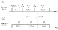
ここで、図3に示すように、ユニット制御部11は、1フレームを3つに区切る。すなわち、プリアンブルの次のビットから数えてn(nは自然数)ビット目の一部にマーキングを行う。同様にして、ユニット制御部11は、nビット目の次のビットから数えてn+1ビット目の一部、当該n+1ビット目の次のビットから数えてn+2ビット目の一部にそれぞれマーキングを行う。以後、フレームにおいて、マーキングされた範囲をマーキングエリアAとする。このように、マーキングすることで、各マーキングエリアAを境界としてフレームを第1〜第3のフレーム片51〜53に区切ることができる。また、ユニット制御部11は、フレーム片51〜53毎に誤り検出用ビットBeを含ませる。
Here, as shown in FIG. 3, the
本実施形態において、マーキングは、送信アンテナ12aから送信される空気圧信号の電波を一定時間Tだけ止めることで行われる。これにより、図2(b)に示すように、一定時間Tにおける信号の振幅がゼロとなる。この一定時間Tは、マーキングされたビットの情報に影響を与えない程度に短く、かつノイズがマーキングであると誤認識されない程度に長く設定される。一定時間Tは、例えば1/20〜1/2ビットの送信に要する時間に設定される。
In the present embodiment, the marking is performed by stopping the radio wave of the pneumatic signal transmitted from the
<車載機>
図1に示すように、車載機20は、車載制御部21と、受信部22と、受信アンテナ22aとを備える。車載制御部21はコンピュータユニットによって構成されるとともに、不揮発性のメモリ21aを備える。このメモリ21aには、各センサユニット10のIDコードが記憶されている。
<In-vehicle device>
As shown in FIG. 1, the in-
また、図4に示すように、受信部22は、増幅器24と、IF変換部25と、復調部26とを備える。復調部26は、車載制御部21におけるフレーム再生処理部30に接続されている。
As illustrated in FIG. 4, the
受信アンテナ22aは空気圧信号を受信すると、その受信信号を増幅器24に出力する。増幅器24は、受信信号を増幅し、それをIF変換部25に出力する。IF変換部25は、増幅器24からの信号を中間周波数(IF;Intermediate Frequency)に変換し、それを復調部26に出力する。
When receiving the air pressure signal, the receiving
復調部26は、FM検波器27と、波形整形器28と、RSSI検出回路29とを備える。FM検波器27は、図2(a)に示すように、IF変換部25からの信号の周波数が「1」に対応する高周波数f1のときHiレベルの信号を生成し、「0」に対応する低周波数f2のときLoレベルの信号を生成する。一定時間Tにおいては、両周波数f1,f2の何れでもない。このため、一定時間Tにおいては、信号レベルが不定値となることで不定値領域が形成される。FM検波器27において検波された信号は波形整形器28に出力される。
The
波形整形器28は、図2(c)に示すように、FM検波器27からの信号の波形を整形し、それをフレーム再生処理部30に出力する。これにより、一定時間Tにおける不定値領域は除去される。具体的には、波形整形器28は、図4に示すように、ローパスフィルタ28aと、比較器28bと備える。ローパスフィルタ28aは、図2(a)の円中に拡大して示すように、不定値領域における高周波成分を除去して、それを比較器28bに出力する。比較器28bは、図2(a)に示すように、不定値領域における信号レベルがHiレベル及びLoレベル間の値に設定されるしきい値以上であればそれをHiレベルとする。すなわち、上記高周波成分を除去された信号がしきい値未満とならない程度に一定時間Tは短く設定される。
The
なお、一定時間Tが比較的長い場合(例えば1/2ビットの送信に要する時間)には、一定時間Tの直前のステータス(「0」又は「1」)を継続させてもよい。これにより、マーキングを行ったビットについても、他のビットと同様に情報を付加させることができる。 If the fixed time T is relatively long (for example, the time required for 1/2 bit transmission), the status (“0” or “1”) immediately before the fixed time T may be continued. Thereby, information can be added to the marked bits as well as other bits.
一方、図4に示すように、RSSI検出回路29は、IF変換部25からの信号の受信信号強度(RSSI;Receive Signal Strength Indication)を検出し、その検出結果をフレーム再生処理部30に出力する。RSSI検出回路29は、図2(b)に示すように、一定時間Tにおいてはゼロに近似した信号強度の信号、一定時間T以外の時間においては一定の信号強度の信号を受ける。従って、フレーム再生処理部30は、信号強度がゼロであると判断した一定時間T、すなわちマーキングエリアAを認識することができる。ここで、ノイズ等によって微少な信号強度が検出された場合に信号強度が完全にゼロとならなくてもゼロと判断される。フレーム再生処理部30は、最初にマーキングエリアAを認識したときから次にマーキングエリアAを認識するまでのビット数をカウントする。そして、カウントしたビット数がnビットであるときは第1のフレーム片51を受信した旨判断し、カウントしたビット数がn+1ビットであるときは第2のフレーム片52を受信した旨判断し、カウントしたビット数がn+2ビットであるときは第3のフレーム片53を受信した旨判断する。すなわち、メモリ21aには各フレーム片51〜53と、マーキングエリアA間のビット数とが関連付けられた情報が記憶されている。従って、その情報をもとに上記判断が可能となる。
On the other hand, as shown in FIG. 4, the
例えば、図3に示すように、最初のフレームにおける第1のフレーム片51にビットエラーがあるとする。このエラーは、例えばパリティチェックや巡回冗長検査を通じて車載制御部21において検出される。本例では、フレーム片51〜53毎に誤り検出用ビットBeが含まれているため、何れのフレーム片51〜53にビットエラーがあるかが検出可能となる。
For example, as shown in FIG. 3, it is assumed that there is a bit error in the
フレーム再生処理部30は、受信したフレームのうち、第1のフレーム片51にビットエラーがあるとしてそれを破棄して、第2のフレーム片52及び第3のフレーム片53をメモリ21aに一時的に記憶する。そして、フレーム再生処理部30は、2回目のフレームを受信する際に、第1のフレーム片51を受信した時点、すなわち、同フレームにおける最初のマーキングエリアAに達した時点でその第1のフレーム片51と、メモリ21aに記憶される第2のフレーム片52及び第3のフレーム片53とでフレームを再生する。具体的には、図3の矢印で示すように、第1〜第3のフレーム片51〜53を並び替える。これにより、第1のフレーム片51にビットエラーがあった場合であっても、2回目のフレームを全て受信する前に、フレームの全てを認識することができる。よって、より迅速にフレームを認識することができる。
The frame
また、受信環境が悪くビットエラーが多い場合であっても、フレームを正常に認識させることができる。例えば、図5に示すように、1回目のフレームにおける第1のフレーム片51及び第3のフレーム片53にビットエラーがあって、2回目のフレームにおける第2のフレーム片52及び第3のフレーム片53にビットエラーがあって、3回目のフレームにおける第2のフレーム片52にビットエラーがあるとする。この場合であっても、図5の矢印で示すように、2回目のフレームから第1のフレーム片51、1回目のフレームから第2のフレーム片52、3回目のフレームから第3のフレーム片53がそれぞれ得られる。よって、受信環境が悪い場合であっても、フレームを再生することができる。
Even if the reception environment is bad and there are many bit errors, the frame can be recognized normally. For example, as shown in FIG. 5, there is a bit error in the
車載制御部21は、フレームを認識すると、同フレームに含まれるIDコードと、自身のメモリ21aに記憶されるIDコードとの照合を通じて、何れのタイヤに関する情報であるかを特定する。そして、車載制御部21は、特定されたタイヤにおける空気圧が閾値以下となった旨判断したとき、特定されたタイヤに空気圧異常がある旨を、例えばインジゲータ(図示略)でユーザに警告する。
When the vehicle-mounted
なお、本例ではマーキングが正しく受信できない場合であっても、車載制御部21は、フレームがパリティチェック等を通じて正常である旨判断したときには、マーキングに関わらずそのフレームを認識する。これは、たとえマーキングが正常に受信できなかった場合であっても、フレームのビット列を認識することが可能だからである。
In this example, even if the marking cannot be received correctly, the in-
以上、説明した実施形態によれば、以下の効果を奏することができる。
(1)フレームのうち一部が正常に受信できなかった場合であっても、正常に受信できたフレーム片が記憶される。そして、次のフレームにおいて、前回正常に受信できなかったフレーム片を受信した時点で、当該フレーム片と前記記憶されたフレーム片とに基づきフレームが再生される。従って、次のフレームの全ての受信を待たずに、フレームの全てを認識することができる。これにより、通信をより迅速に行うことができる。
As described above, according to the embodiment described above, the following effects can be obtained.
(1) Even when some of the frames cannot be received normally, the frame pieces that can be received normally are stored. In the next frame, when a frame piece that has not been normally received last time is received, a frame is reproduced based on the frame piece and the stored frame piece. Therefore, it is possible to recognize all the frames without waiting for reception of all the next frames. Thereby, communication can be performed more rapidly.
(2)受信環境が悪い場合であっても、各フレームにおいて正常に受信できたフレーム片を寄せ集めてフレームを再生することができる。よって、センサユニット10及び車載機20間での通信をより高い確率で成立させることができる。
(2) Even when the reception environment is poor, it is possible to reproduce frames by collecting frame pieces that have been normally received in each frame. Therefore, communication between the
(3)マーキングが行われることで一定時間Tにおいて信号レベルの不定値領域が形成される。この不定値領域は、波形整形器28を通じて除去される。具体的には、一定時間Tの直前と同一の信号レベルとされる。これにより、マーキングを行ったビットについても、その他のビットと同様に情報を含ませることができる。よって、マーキングを行うことでビットが無駄となることがない。
(3) By performing marking, an indefinite value region of signal level is formed at a fixed time T. This indefinite value region is removed through the
(第2の実施形態)
以下、本発明の第2の実施形態について、図6及び図7を参照して説明する。この実施形態は、マーキングの手法として周波数を偏移させる点が上記第1の実施形態と異なっている。以下、第1の実施形態との相違点を中心に説明する。
(Second Embodiment)
Hereinafter, a second embodiment of the present invention will be described with reference to FIGS. This embodiment is different from the first embodiment in that the frequency is shifted as a marking method. Hereinafter, a description will be given focusing on differences from the first embodiment.
図6に示すように、第1の実施形態におけるRSSI検出回路29に替えて周波数偏移検出器35が設けられている。その他は第1の実施形態と同様に構成される。
送信部12は、変調する際に「1」及び「0」に対応する周波数f1,f2の他に、特定のビット(マーキングエリアAを有するビット)において周波数f3に変調する。この周波数f3は周波数f1,f2より高く設定されている。本例では特定のビットによりフレームが第1〜第3のフレーム片51〜53に区切られる。この変調された空気圧信号は送信アンテナ12aを介して無線送信される。
As shown in FIG. 6, a
The
受信アンテナ22aを介して受信された空気圧信号は、増幅器24及びIF変換部25を通じてFM検波器27及び周波数偏移検出器35に出力される。FM検波器27は、図7(a)に示すように、IF変換部25からの信号を周波数f1〜f3に応じて検波し、それを波形整形器28に出力する。ここで、周波数f1は「0」に、周波数f2は「1」に、周波数f3は「1´」にそれぞれ対応している。そして、検波されることでフレームは、「0」に対応するLoレベルと、「1」に対応するHiレベルと、「1´」に対応するHi´レベルとなる。波形整形器28は、Loレベル及びHiレベル間にしきい値を設定して、しきい値以上であればHiレベルとして、しきい値未満であればLoレベルとする。従って、Hi´レベルはHiレベルとして認識される。このため、図2(c)に示すように、受信された空気圧信号は「0」及び「1」からなる信号に復調される。従って、マーキングの対象となっているビットについても情報を付加させることができる。
The air pressure signal received via the receiving
周波数偏移検出器35は、IF変換部25からの信号を通じて周波数f3に偏移したことを検出する。例えば、図7(a)に示すように、両周波数f2,f3の差を差分Δfとする。また、両周波数f1,f2の中央値から周波数f1,f2までの値を差分ΔEとする。周波数偏移検出器35は、図7(b)に示すように、差分ΔEを超えて偏移した周波数、すなわち周波数f2,f3間での周波数偏移を検出し、その検出結果をフレーム再生処理部30に出力する。フレーム再生処理部30は、周波数偏移検出器35の検出結果に基づき差分ΔEを超えて偏移した周波数が周波数f3となった旨判断したとき、そこがマーキングエリアAであると認識する。フレーム再生処理部30は、第1の実施形態と同様に、マーキングエリアA間のビット数に基づき第1〜第3のフレーム片51〜53を判断してフレームを再生する。
The
なお、周波数を周波数f3に偏移させることで、僅かに占有帯域幅が増加するものの、通信自体に影響を及ぼすものではない。
以上、説明した実施形態によれば、以下の効果を奏することができる。
Note that shifting the frequency to the frequency f3 slightly increases the occupied bandwidth, but does not affect the communication itself.
As described above, according to the embodiment described above, the following effects can be obtained.
(4)「0」及び「1」に対応する周波数f1,f2以外の周波数f3に偏移させることでマーキングを行うことで、フレームを第1〜第3のフレーム片51〜53に区切る。これにより、車載機20においてフレームを再生することが可能となって、第1の実施形態と同様の効果を奏することができる。
(4) Marking is performed by shifting to the frequency f3 other than the frequencies f1 and f2 corresponding to “0” and “1”, thereby dividing the frame into first to
(第3の実施形態)
以下、本発明の第3の実施形態について、図8及び図9を参照して説明する。この実施形態は、マーキングの手法として位相を変化させる点が上記第1の実施形態と異なっている。以下、第1の実施形態との相違点を中心に説明する。なお、この実施形態のTPMSは、図1に示す第1の実施形態のTPMSとほぼ同様の構成を備えている。
(Third embodiment)
Hereinafter, a third embodiment of the present invention will be described with reference to FIGS. This embodiment is different from the first embodiment in that the phase is changed as a marking method. Hereinafter, a description will be given focusing on differences from the first embodiment. The TPMS of this embodiment has substantially the same configuration as the TPMS of the first embodiment shown in FIG.
図8に示すように、第1の実施形態におけるRSSI検出回路29に替えて位相検波器36が設けられている。その他は第1の実施形態と同様に構成される。
また、図1の破線で示すように、送信部12には位相器37が設けられている。
As shown in FIG. 8, a phase detector 36 is provided in place of the
Further, as indicated by a broken line in FIG. 1, the
送信部12は、変調する際に特定のビット(マーキングエリアAを有するビット)のみ、位相器37を通じて位相を基準位相に対して180°ずらして無線送信する。この基準位相とは、上記搬送波の位相である。本例では特定のビットの位相をずらすことによりフレームが第1〜第3のフレーム片51〜53に区切られる。
The transmitting
受信アンテナ22aを介して受信された空気圧信号は、増幅器24及びIF変換部25を通じてFM検波器27及び位相検波器36に出力される。FM検波器27は、図9(a)に示すように、周波数f1,f2に応じてHiレベル及びLoレベルに検波し、それをフレーム再生処理部30に出力する。このように、周波数に応じて検波されるため、検波に位相のずれは影響しない。
The air pressure signal received via the receiving
位相検波器36は、図9(b)に示すように、基準位相に対して位相が180°ずれたことを検出し、その検出結果をフレーム再生処理部30に出力する。フレーム再生処理部30は、位相検波器36の検出結果に基づき基準位相に対する位相が180°ずれた旨認識したとき、上記特定のビット、すなわち、それがマーキングエリアAであると認識する。フレーム再生処理部30は、第1の実施形態と同様に、マーキングエリアA間のビット数に基づき第1〜第3のフレーム片51〜53を判断してフレームを再生する。
As shown in FIG. 9B, the phase detector 36 detects that the phase is shifted by 180 ° with respect to the reference phase, and outputs the detection result to the frame
以上、説明した実施形態によれば、第1の実施形態の効果に加え、以下の効果を奏することができる。
(5)特定のビットにおける信号の位相を変化させることでマーキングを行ってフレームを区切る。これにより、車載機20においてフレームを再生することが可能となって、第1の実施形態と同様の効果を奏することができる。
As described above, according to the embodiment described above, the following effects can be obtained in addition to the effects of the first embodiment.
(5) Marking is performed by changing the phase of a signal at a specific bit to divide the frame. Thereby, it becomes possible to reproduce | regenerate a flame | frame in the
(第4の実施形態)
以下、本発明の第4の実施形態について、図10及び図11を参照して説明する。この実施形態は、マーキングの手法が長いパルスを入れることである点が上記第1の実施形態と異なっている。以下、第1の実施形態との相違点を中心に説明する。なお、この実施形態のTPMSは、図1に示す第1の実施形態のTPMSとほぼ同様の構成を備えている。
(Fourth embodiment)
Hereinafter, a fourth embodiment of the present invention will be described with reference to FIGS. 10 and 11. This embodiment is different from the first embodiment in that the marking method is to put a long pulse. Hereinafter, a description will be given focusing on differences from the first embodiment. The TPMS of this embodiment has substantially the same configuration as the TPMS of the first embodiment shown in FIG.
図10に示すように、第1の実施形態におけるRSSI検出回路29に替えて3チップ検出器38が設けられている。3チップ検出器38は、波形整形器28及びフレーム再生処理部30間に接続されている。その他は第1の実施形態と同様に構成される。
As shown in FIG. 10, a 3-
本例では、マンチェスター符号を利用して通信が行われている。ここで、マンチェスター符号とは、信号レベルのHiレベル及びLoレベル間での変化を「0」及び「1」の符号で表すデータ伝送方式である。具体的には、LoレベルからHiレベルへの変化を「0」で表し、HiレベルからLoレベルへの変化を「1」で表す。 In this example, communication is performed using the Manchester code. Here, the Manchester code is a data transmission method in which a change in signal level between the Hi level and the Lo level is represented by codes “0” and “1”. Specifically, the change from the Lo level to the Hi level is represented by “0”, and the change from the Hi level to the Lo level is represented by “1”.
ユニット制御部11は、マンチェスター符号を利用して空気圧信号(フレーム)を生成し、それを送信部12に出力する。送信部12は、ユニット制御部11からの空気圧信号をFSK変調し、それを送信アンテナ12aを介して送信する。
The
本例では、特定の範囲(マーキングエリアA)に3チップ分(1ビット=2チップ)のHiレベルが挿入される。これにより、フレームにマーキングがされて、同フレームが第1〜第3のフレーム片51〜53に区切られる。
In this example, the Hi level of 3 chips (1 bit = 2 chips) is inserted in a specific range (marking area A). Thereby, the frame is marked and the frame is divided into first to
受信アンテナ22aを介して受信された空気圧信号は、増幅器24及びIF変換部25を通じてFM検波器27に出力される。FM検波器27は、図11(a)に示すように、IF変換部25からの信号の周波数に応じてHiレベル及びLoレベルからなる信号に検波し、それを波形整形器28に出力する。波形整形器28は、波形を整形し、それをフレーム再生処理部30及び3チップ検出器38に出力する。
The air pressure signal received via the receiving
3チップ検出器38は、信号レベルがHiレベルとなっているチップ数を検出する。3チップ検出器38は、図11(b)に示すように、Hiレベルが3チップ連続したとき、パルスをフレーム再生処理部30に出力する。
The 3-
フレーム再生処理部30は、3チップ検出器38の検出結果に基づき3チップ連続でHiレベルとなる範囲、すなわちマーキングエリアAを認識する。フレーム再生処理部30は、第1の実施形態と同様に、マーキングエリアA間のビット数に基づき第1〜第3のフレーム片51〜53を判断してフレームを再生する。
Based on the detection result of the 3-
ここで、マンチェスター符号においては、各ビットにおいて信号レベルがHiレベル及びLoレベル間で切り替わる。このため、通常の通信において、3チップ連続してHiレベルとなることはない。このルールを利用して3チップ連続のHiレベルを通じてマーキングを行うことができる。すなわち、本例では3チップ連続のHiレベルがフレームにおける通信に利用されないビットの組み合わせに相当する。 Here, in the Manchester code, the signal level is switched between the Hi level and the Lo level in each bit. For this reason, in normal communication, the Hi level is not continuously increased for three chips. By using this rule, marking can be performed through the Hi level of three consecutive chips. In other words, in this example, the Hi level of three consecutive chips corresponds to a combination of bits that are not used for communication in a frame.
なお、本例ではマーキングが正しく受信できない場合には、3チップ連続してHiレベルとならないため、意図しない「0」又は「1」の情報となる。このため、本実施形態においては上記各実施形態と異なってマーキングが正しく受信できない場合にはそのフレームは破棄される。 In this example, if the marking cannot be received correctly, the Hi level is not continuously set for three chips, and therefore information of unintended “0” or “1” is obtained. For this reason, in this embodiment, unlike the above embodiments, if the marking cannot be received correctly, the frame is discarded.
以上、説明した実施形態によれば、第1の実施形態の効果に加え、以下の効果を奏することができる。
(6)3チップ分のHiレベルが挿入されることでマーキングが行われる。この場合、マーキングを行うにあたって振幅、位相又は周波数を変化させる必要がない。このため、より容易な構成にてマーキングを行うことができる。
As described above, according to the embodiment described above, the following effects can be obtained in addition to the effects of the first embodiment.
(6) Marking is performed by inserting a Hi level of 3 chips. In this case, it is not necessary to change the amplitude, phase, or frequency when performing marking. For this reason, marking can be performed with an easier configuration.
(第5の実施形態)
以下、本発明の第5の実施形態について、図12及び図13を参照して説明する。この実施形態においては、本発明が電子キーシステムに適用されている。
(Fifth embodiment)
Hereinafter, a fifth embodiment of the present invention will be described with reference to FIGS. 12 and 13. In this embodiment, the present invention is applied to an electronic key system.
図12に示すように、車両のユーザによって所持される電子キー60は、キー制御部61と、送信部12と、送信アンテナ12aと、解錠スイッチ62と、施錠スイッチ63とを備える。
As shown in FIG. 12, the electronic key 60 possessed by the user of the vehicle includes a
キー制御部61は、上記各実施形態におけるユニット制御部11と同様に構成される。また、キー制御部61は、電子キー60に固有のIDコードが記憶されるメモリ61aを備える。送信部12及び送信アンテナ12aは、第1の実施形態と同様に構成される。
The
解錠スイッチ62又は施錠スイッチ63が操作されると、その旨の操作信号がキー制御部61に出力される。キー制御部61は、解錠スイッチ62が操作された旨認識すると、送信部12及び送信アンテナ12aを通じてUHF帯の解錠要求信号を無線送信する。キー制御部61は、施錠スイッチ63が操作された旨認識すると、送信部12及び送信アンテナ12aを通じてUHF帯の施錠要求信号を無線送信する。各要求信号は、それぞれ同一の複数のフレームからなる。各フレームにはIDコード等が含まれている。また、各フレームは、上記各実施形態に示した手法にてマーキングが行われることで、第1〜第3のフレーム片51〜53に区切られる。
When the
受信部22は、受信アンテナ22aを通じて受信した解錠要求信号又は施錠要求信号を復調して、それを車載制御部21に出力する。車載制御部21は、解錠要求信号におけるフレームに含まれるIDコードと、メモリ21aに記憶されるIDコードとの照合が成立したとき、車両ドアを解錠する。また、車載制御部21は施錠要求信号におけるフレームに含まれるIDコードと、メモリ21aに記憶されるIDコードとの照合が成立したとき、車両ドアを施錠する。ここで、車載制御部21(正確にはフレーム再生処理部30)は、上記各実施形態と同様に、マーキングエリアA間のビット数のカウントを通じて各フレーム片51〜53を認識する。
The receiving
ここで、車載制御部21は、消費電力低減の観点から一定周期毎に受信部22を受信可能状態とする。すなわち、受信部22は、常に受信可能状態とされているわけではない。従って、図13(a)及び(b)に示すように、フレームの途中で受信可能状態となることもある。本例では、第2のフレーム片52の途中で受信可能状態となっている。この場合、途中で受信を開始した第2のフレーム片52は破棄されて、第3のフレーム片53をメモリ21aに一時的に記憶させる。この第3のフレーム片53は、上述のようにマーキングエリアA間のビット数に基づき判断される。そして、図13(a)の矢印で示すように、2回目のフレームにおいて第1のフレーム片51及び第2のフレーム片52を受信した時点でそれらと、メモリ21aに記憶される第3のフレーム片53とでフレームを再生する。従って、フレームの途中から受信を開始した場合であっても、より迅速にフレームの全てを認識することができる。
Here, the vehicle-mounted
なお、電子キーシステムにおいても、上記図5を参照して説明したように、フレーム片にビットエラーがある場合であっても、複数のフレームにおけるフレーム片が組み合わされることで、フレームの再生が可能である。 In the electronic key system as well, as described with reference to FIG. 5 above, even when there is a bit error in the frame piece, it is possible to reproduce the frame by combining the frame pieces in a plurality of frames. It is.
以上、説明した実施形態によれば、第1の実施形態の効果に加え、以下の効果を奏することができる。
(6)フレームの途中から受信可能状態となった場合であっても、同フレームにおいて正常に受信したフレーム片53と、次のフレームにおいて受信したフレーム片51,52とが組み合わされることでフレームの再生ができる。
As described above, according to the embodiment described above, the following effects can be obtained in addition to the effects of the first embodiment.
(6) Even when the frame is ready to be received from the middle of the frame, the
なお、上記実施形態は、これを適宜変更した以下の形態にて実施することができる。
・第1の実施形態においては、一定時間Tは、1/20〜1/2ビットの送信に要する時間に設定されていた。しかし、一定時間Tは上記範囲に限らず、例えば1ビットの送信に要する時間に設定してもよい。
In addition, the said embodiment can be implemented with the following forms which changed this suitably.
In the first embodiment, the fixed time T is set to a time required for 1/20 to 1/2 bit transmission. However, the fixed time T is not limited to the above range, and may be set to a time required for 1-bit transmission, for example.
・上記各実施形態においては、2つのマーキングエリアA間のビット数をカウントしていた。しかし、マーキングエリアA間の経過時間を計測してもよい。
・上記各実施形態におけるマーキングの手法を適宜組み合わせてもよい。
In each of the above embodiments, the number of bits between the two marking areas A is counted. However, the elapsed time between the marking areas A may be measured.
-You may combine the method of marking in each said embodiment suitably.
・第4の実施形態においては、FSK変調方式が採用されていたが、変調方式はこれに限らず、例えばASK(Amplitude Shift Keying)変調方式やPSK(Phase Shift Keying)変調方式を採用してもよい。また、これら変調方式以外の全てのデジタル通信方式を採用することができる。 In the fourth embodiment, the FSK modulation method is adopted. However, the modulation method is not limited to this. For example, an ASK (Amplitude Shift Keying) modulation method or a PSK (Phase Shift Keying) modulation method may be adopted. Good. All digital communication methods other than these modulation methods can be employed.
・第4の実施形態においては、3チップ連続のHiレベルが挿入されることでマーキングが行われていたが、3チップ連続のLoレベルが挿入されることでマーキングを行ってもよい。3チップ連続のLoレベルも同様の理由から通常の通信においては使われない。 In the fourth embodiment, the marking is performed by inserting the Hi level of three chips continuously, but the marking may be performed by inserting the Lo level of three chips. For the same reason, the three-chip Lo level is not used in normal communication.
・上記各実施形態においては、各フレームにおいて、マーキングが行われるビットの位置は同一であった。しかし、フレーム毎にマーキングが行われるビットの位置をずらしてもよい。具体的には、図14に示すように、1回目のフレームにおいては第1のフレーム片51を7ビットとして、第2のフレーム片52を9ビットとする。また、2回目のフレームにおいては第1のフレーム片51を6ビットとして、第2のフレーム片52を10ビットとする。この例では、フレームが送信される度に、そのフレームにおける第1のフレーム片51はビット数が一定範囲内で1ずつ減る降順となって、第2のフレーム片52はビット数が一定範囲内で1ずつ増える昇順となる。しかし、予めセンサユニット10及び車載機20間で各フレームのフレーム片のビット数が取り決められていればこれに限定されない。これにより、フレーム片のビット数をカウントすることで、何れのフレームにおける何れのフレーム片であるかを認識することができる。
In each of the above embodiments, the position of the bit where marking is performed is the same in each frame. However, the position of the bit where marking is performed may be shifted for each frame. Specifically, as shown in FIG. 14, in the first frame, the
しかし、本構成においては、フレーム片を組み合わせるときに不足するビットが発生する。例えば、1回目のフレームにおける第2のフレーム片52(9ビット)と、2回目のフレームにおける第1のフレーム片51(6ビット)とが組み合わされても、本例の全フレームにおける16ビットに対して1ビット分不足する。これを解決するべく、車載機20において各フレーム片のビット数が組み替えられる。
However, in this configuration, there are insufficient bits when combining frame pieces. For example, even if the second frame piece 52 (9 bits) in the first frame and the first frame piece 51 (6 bits) in the second frame are combined, the 16 bits in all the frames of this example On the other hand, one bit is insufficient. In order to solve this, the number of bits of each frame piece is rearranged in the in-
例えば、図15(a)に示すように、送信されるフレームは、第1のフレーム片51が8ビット、第2のフレーム片52が10ビット、第3のフレーム片53が12ビットであるとする。車載制御部21は、マーキングエリアA間のビット数を通じて第1〜第3のフレーム片51〜53を認識すると、図15(b)に示すように、各フレーム片が10ビットとなるように組み替える。具体的には、第2のフレーム片52の1ビット目及び2ビット目を、第1のフレーム片51の9ビット目及び10ビット目とする。そして、第3のフレーム片53の1ビット目及び2ビット目を、第2のフレーム片52の9ビット目及び10ビット目とする。このように、各フレーム片が10ビットとなるように組み替えられた後にフレーム片が組み合わされることで、上記のようなビットの不足が生じない。本例では、各フレーム片は10ビットに組み替えられていたが、10ビットでなくてもよい。
For example, as shown in FIG. 15A, the
・上記各実施形態においては、図3に示すように、フレーム片51〜53毎に誤り検出用ビットBeを含ませることで、何れのフレーム片51〜53にビットエラーがあるかが検出可能であった。しかし、フレーム毎に検出用ビットを含ませてもよい。この場合には、何れのフレーム片51〜53にビットエラーがあるかが検出できないため、複数のフレームにおけるフレーム片51〜53の全ての組み合わせから複数のフレームを再生する。そして、再生されたフレームにおける誤り検出用ビットを通じてエラーチェックを行う。本構成においては、各フレームにおける誤り検出用ビットの数を低減すること、ひいてはフレーム長を短くすることができる。
In each of the above embodiments, as shown in FIG. 3, it is possible to detect which
・上記各実施形態においては、無線の通信システムであったが、光等の有線通信システムであってもよい。
・第4の実施形態においては、通信に利用されないビットの組み合わせは3チップ連続のHiレベルであったが、通信に利用されないビットの組み合わせであればこれに限定されない。
In each of the above embodiments, a wireless communication system is used, but a wired communication system such as light may be used.
In the fourth embodiment, the combination of bits that are not used for communication is the Hi level of three chips in a row, but the combination is not limited to this as long as the combination of bits is not used for communication.
・上記各実施形態においては、フレームは第1〜第3のフレーム片51〜53の3つに区切られていた。しかし、フレームを区切る数は複数であれば3つに限らない。フレームを区切る数に応じてマーキングの回数が決まる。
In each of the above embodiments, the frame is divided into three frames, the first to
ここで、フレームが例えば8つのフレーム片に区切られている構成において、その一部のマーキングが認識できなかった場合について説明する。なお、本例ではマーキング手法として第1〜第3の実施形態が適用される。また、フレーム毎(正確にはフレームの最後)に誤り検出用ビットが付加される。フレーム再生処理部30は、図16に示すように、マーキングエリアA間のビット数に基づき各フレーム片51〜58を認識する。ここで、フレーム再生処理部30は、マーキングエリアA間のビット数が、各フレーム片のうち最長のビット数(本例では12ビット)を超えている場合には、その間のマーキングエリアAが認識できなかった旨判断する。例えば、マーキングエリアA間のビット数が19ビットである場合には、第5のフレーム片55と第6のフレーム片56との間のマーキングエリアAが認識されなかった旨判断する。この場合であっても、上記フレーム毎に付加される誤り検出用ビットを通じてフレームにビットエラーがなければ、そのフレームは採用される。さらに、第5のフレーム片55及び第6のフレーム片56を1つのフレーム片として取り扱って、他のフレームにおけるフレーム片と組み合わせてフレーム再生してもよいし、認識不可だった箇所にマーキングを自動で付加して再生してもよい。
Here, a case where a part of the marking cannot be recognized in a configuration in which the frame is divided into, for example, eight frame pieces will be described. In this example, the first to third embodiments are applied as marking methods. Further, an error detection bit is added for each frame (more precisely, at the end of the frame). As shown in FIG. 16, the frame
次に、前記実施形態から把握できる技術的思想をその効果と共に記載する。
(イ)請求項2に記載の送信装置において、前記一定時間は1ビット分の送信に要する時間より短く設定され、前記フレームは前記受信部において復調されることで、その復調信号の前記一定時間に対応する部分に信号レベルの不定値領域が形成され、前記受信部に設けられるとともに、前記不定値領域を含むビットにおいて、前記不定値領域をその直前の信号レベルと同一とすることで、前記不定値領域を除去する波形整形器を備えた送信装置。
Next, the technical idea that can be grasped from the embodiment will be described together with the effects.
(A) In the transmitter according to claim 2, the predetermined time is set shorter than a time required for transmission of one bit, and the frame is demodulated by the receiving unit, whereby the predetermined time of the demodulated signal is set. An indefinite value area of a signal level is formed in a portion corresponding to the signal level and is provided in the receiving unit, and in the bit including the indeterminate value area, the indefinite value area is made the same as the signal level immediately before, A transmission apparatus including a waveform shaper that removes an indefinite value region.
同構成によれば、マーキングが行われることで形成される信号レベルの不定値領域が波形整形器を通じて除去される。これにより、マーキングを行ったビットについても、その他のビットと同様に情報を含ませることができる。 According to this configuration, the indefinite value region of the signal level formed by marking is removed through the waveform shaper. Thereby, information can be included also about the bit which performed marking like other bits.
(ロ)送信部から受信部に同一のフレームを複数回に亘って送信する通信システムにおいて、前記送信部は、前記フレームの途中において、その一部分の信号をその他の部分と異なる態様で変化させることでマーキングを行い、同マーキングが行われたマーキングエリアを境界として前記フレームをそれぞれ長さの異なるフレーム片に区切り、前記受信部は、前記受信したフレームに基づき前記マーキングエリアを認識し、その前記マーキングエリアの間隔に基づき、何れのフレーム片であるかを判断するとともに、最初のフレームのうち正常に受信した前記フレーム片を記憶し、次のフレームのうち前記最初のフレームにおいて正常に受信できなかった前記フレーム片を正常に受信したとき、当該フレーム片と前記記憶されたフレーム片とに基づき前記フレームを再生する通信システム。 (B) In a communication system in which the same frame is transmitted from the transmission unit to the reception unit over a plurality of times, the transmission unit changes a part of the signal in a different manner from the other part in the middle of the frame. The frame is divided into frame pieces having different lengths with the marking area where the marking is performed as a boundary, and the receiving unit recognizes the marking area based on the received frame, and the marking Based on the interval of the area, it is determined which frame fragment is received, the frame fragment received normally in the first frame is stored, and the first frame in the next frame was not received normally When the frame piece is received normally, the frame piece and the stored frame piece Communication system for reproducing the frame basis.
同構成によれば、フレームにおいて、その一部が正常に受信できなかった場合であっても、正常に受信できたフレーム片が記憶される。そして、次のフレームにおいて、前回正常に受信できなかったフレーム片を受信した時点で、当該フレーム片と前記記憶されたフレーム片とに基づきフレームが再生される。従って、次のフレームの全ての受信を待たずに、フレームの全てを認識することができる。これにより、通信をより迅速に行うことができる。 According to the configuration, even if a part of the frame cannot be normally received, the frame piece that has been normally received is stored. In the next frame, when a frame piece that has not been normally received last time is received, a frame is reproduced based on the frame piece and the stored frame piece. Therefore, it is possible to recognize all the frames without waiting for reception of all the next frames. Thereby, communication can be performed more rapidly.
(ハ)請求項1〜5の何れか一項に記載の送信装置において、前記フレームは、ビット毎における信号レベルをHi及びLo間で変化させることにより符号化され、前記マーキングは、ビット長の半分の長さであるチップを3つ連続でHi又はLoとすることで行われる送信装置。
(C) In the transmission device according to any one of
信号レベルのHi及びLo間での変化で符号化する方式においては、通常、3チップ連続で信号レベルがHi又はLoとなることはない。上記構成によれば、3チップ連続で信号レベルをHi又はLoとすることでマーキングが行われる。このマーキングにおいては、例えば振幅、位相や周波数を変化させる必要がなく、より容易な構成にてマーキングを行うことができる。 In a method of encoding by changing the signal level between Hi and Lo, the signal level does not normally become Hi or Lo for three consecutive chips. According to the above configuration, marking is performed by setting the signal level to Hi or Lo continuously for three chips. In this marking, for example, it is not necessary to change the amplitude, phase and frequency, and marking can be performed with a simpler configuration.
10…センサユニット、11…ユニット制御部、12…送信部、20…車載機(受信装置)、21…車載制御部、22…受信部、26…復調部、27…FM検波器、28…波形整形器、29…RSSI検出回路、30…フレーム再生処理部、35…周波数偏移検出器、36…位相検波器、37…位相器、38…3チップ検出器、51〜53…第1〜第3のフレーム片。
DESCRIPTION OF
Claims (14)
前記フレームの途中において、その一部分の信号をその他の部分と異なる態様で変化させることでフレームにて伝送するデータの内容には情報として含まれない態様でマーキングを行い、同マーキングが行われたマーキングエリアを境界として前記フレームをそれぞれ長さの異なるフレーム片に区切って送信し、前記複数のフレームにおける前記フレーム片は組み合わせてフレームが再生可能とされる送信装置。 In a transmission device that transmits the same frame multiple times,
In the middle of the frame, marking is performed in a manner that is not included as information in the content of data transmitted in the frame by changing the signal of a part of the frame in a manner different from that of the other parts. A transmission apparatus in which the frame is divided into frame pieces having different lengths and transmitted with an area as a boundary, and the frame pieces in the plurality of frames can be combined to reproduce a frame.
前記マーキングは、送信する信号の電波を一定時間だけ止めることで行われる送信装置。 The transmission apparatus according to claim 1,
The marking is a transmission device that is performed by stopping radio waves of a signal to be transmitted for a certain period of time.
前記マーキングエリアを除くフレームを複数値の周波数に変調し、前記マーキングエリアにおけるフレームを前記複数値の周波数と異なる周波数に変調することで前記マーキングを行う送信装置。 The transmission apparatus according to claim 1 or 2,
A transmitter that performs the marking by modulating a frame excluding the marking area to a plurality of frequencies and modulating a frame in the marking area to a frequency different from the plurality of frequencies.
前記マーキングは、前記マーキングエリアにおける前記フレームの位相を、前記その他の部分における位相に対してずらすことで行われる送信装置。 In the transmission device according to any one of claims 1 to 3,
The transmitter is a transmission device in which the marking is performed by shifting a phase of the frame in the marking area with respect to a phase in the other part.
前記マーキングは、前記フレームにおける通信に利用されないビットの組み合わせにて行われる送信装置。 In the transmission device according to any one of claims 1 to 4,
The marking is performed by a combination of bits not used for communication in the frame.
間欠的に受信可能状態となるとともに、特定のフレームの途中から前記受信可能状態となった場合、前記特定のフレームにおいて受信した後半部分のフレーム片と、前記特定のフレームの次のフレームにおいて受信した前半部分のフレーム片とを組み合わせることで前記フレームを再生する受信装置を備えた通信システム。 In the transmission device according to any one of claims 1 to 5,
When it becomes intermittently receivable and when it becomes receivable from the middle of a specific frame, it is received in the frame part of the latter half received in the specific frame and in the frame following the specific frame A communication system including a receiving device that reproduces the frame by combining the frame pieces of the first half.
前記送信装置は前記各フレーム片に誤り検出用ビットを含ませて送信し、
受信した前記各フレーム片における前記誤り検出用ビットを通じて、前記フレーム片毎のビットエラーの有無を検出し、前記各フレームにおけるビットエラーのないフレーム片を組み合わせることでフレームを再生する受信装置を備えた通信システム。 In the transmission device according to any one of claims 1 to 5,
The transmitter transmits each frame piece including an error detection bit,
A receiving device that detects the presence or absence of a bit error for each frame piece through the error detection bit in each received frame piece, and reproduces the frame by combining the frame pieces with no bit error in each frame; Communications system.
前記送信装置は前記各フレームに誤り検出用ビットを含ませて送信し、
受信した前記複数のフレームにおけるフレーム片を組み合わせることで複数のフレームを再生し、この再生されたフレームにおける前記誤り検出用ビットを通じてビットエラーの有無を検出し、ビットエラーのないフレームを採用する受信装置を備えた通信システム。 In the transmission device according to any one of claims 1 to 5,
The transmitter transmits each frame including an error detection bit,
A receiving apparatus that reproduces a plurality of frames by combining frame pieces in the received plurality of frames, detects presence / absence of a bit error through the error detection bit in the reproduced frame, and employs a frame without a bit error A communication system comprising:
前記マーキングは送信する信号の電波を一定時間だけ止めることで行われるとともに、受信した前記フレームにおける信号強度が著しく低下した旨判断したとき、その部分を前記マーキングエリアとして認識する受信装置。 The receiving device according to claim 9, wherein
The marking is performed by stopping the radio wave of a signal to be transmitted for a certain period of time, and when it is determined that the signal strength in the received frame is significantly reduced, the receiving device recognizes that portion as the marking area.
前記マーキングは前記マーキングエリアを通信に利用される複数値の周波数と異なる周波数に変調されることで行われるとともに、受信した前記フレームにおける周波数が前記複数値の周波数と異なる周波数である旨判断したとき、その部分を前記マーキングエリアとして認識する受信装置。 The receiving device according to claim 9, wherein
The marking is performed by modulating the marking area to a frequency different from a multi-value frequency used for communication, and when it is determined that the frequency in the received frame is a frequency different from the multi-value frequency A receiving apparatus for recognizing the portion as the marking area.
前記マーキングは前記マーキングエリアにおける前記フレームの位相を、前記その他の部分における位相に対してずらすことで行われるとともに、受信した前記フレームにおける位相がその他の部分における位相に対してずれている旨判断したときその部分を前記マーキングエリアとして認識する受信装置。 The receiving device according to claim 9, wherein
The marking is performed by shifting the phase of the frame in the marking area with respect to the phase in the other part, and it is determined that the phase in the received frame is shifted from the phase in the other part. A receiving device that sometimes recognizes the portion as the marking area.
前記マーキングは前記フレームにおける通信に利用されないビットの組み合わせにて行われるとともに、受信した前記フレームにおいて通信に利用されないビットの組み合わせがある旨判断したときその部分を前記マーキングエリアとして認識する受信装置。 The receiving device according to claim 9, wherein
The marking is performed by a combination of bits that are not used for communication in the frame, and a receiving device that recognizes that portion as the marking area when it is determined that there is a combination of bits that are not used for communication in the received frame.
前記受信装置は、前記フレームにおいて前記マーキングが正しく認識されなかった場合であっても、前記フレームに含まれる誤り検出用ビットを通じて前記フレームにビットエラーがない旨判断したとき、前記フレームを採用する受信装置。 In the receiving device according to any one of claims 10 to 12,
The reception apparatus adopts the frame when it is determined that there is no bit error in the frame through an error detection bit included in the frame even when the marking is not correctly recognized in the frame. apparatus.
Priority Applications (3)
| Application Number | Priority Date | Filing Date | Title |
|---|---|---|---|
| JP2011056848A JP2012195687A (en) | 2011-03-15 | 2011-03-15 | Transmitter, receiver, and communication system |
| US13/416,587 US8654818B2 (en) | 2011-03-15 | 2012-03-09 | Transmitter device, receiver device, and communication system |
| CN2012100771274A CN102684832A (en) | 2011-03-15 | 2012-03-14 | Transmitter device, receiver device, and communication system |
Applications Claiming Priority (1)
| Application Number | Priority Date | Filing Date | Title |
|---|---|---|---|
| JP2011056848A JP2012195687A (en) | 2011-03-15 | 2011-03-15 | Transmitter, receiver, and communication system |
Publications (1)
| Publication Number | Publication Date |
|---|---|
| JP2012195687A true JP2012195687A (en) | 2012-10-11 |
Family
ID=46816246
Family Applications (1)
| Application Number | Title | Priority Date | Filing Date |
|---|---|---|---|
| JP2011056848A Pending JP2012195687A (en) | 2011-03-15 | 2011-03-15 | Transmitter, receiver, and communication system |
Country Status (3)
| Country | Link |
|---|---|
| US (1) | US8654818B2 (en) |
| JP (1) | JP2012195687A (en) |
| CN (1) | CN102684832A (en) |
Cited By (1)
| Publication number | Priority date | Publication date | Assignee | Title |
|---|---|---|---|---|
| JPWO2016194720A1 (en) * | 2015-06-05 | 2018-03-22 | ソニーセミコンダクタソリューションズ株式会社 | Signal processing apparatus and method, information processing apparatus and method, and program |
Families Citing this family (9)
| Publication number | Priority date | Publication date | Assignee | Title |
|---|---|---|---|---|
| US9398490B2 (en) * | 2013-03-15 | 2016-07-19 | Trane International Inc. | Method of fragmenting a message in a network |
| WO2015076434A1 (en) * | 2013-11-20 | 2015-05-28 | (주)지엔리티피엠에스 | One-chip radio receiving circuit for vehicle |
| JP6409648B2 (en) * | 2015-03-27 | 2018-10-24 | 株式会社オートネットワーク技術研究所 | Communication device mounting position determination system and determination device |
| JP6423402B2 (en) * | 2015-12-16 | 2018-11-14 | パナソニック インテレクチュアル プロパティ コーポレーション オブ アメリカPanasonic Intellectual Property Corporation of America | Security processing method and server |
| GB2562485A (en) * | 2017-05-15 | 2018-11-21 | Airbus Operations Ltd | Aircraft door control |
| CN111688420B (en) * | 2019-03-14 | 2022-10-18 | 比亚迪股份有限公司 | Vehicle control method and device, vehicle controller and vehicle |
| US10737541B1 (en) * | 2019-08-12 | 2020-08-11 | Infineon Technologies Ag | TPMS autolocalization using direction sensitive antennas |
| CN112333812B (en) * | 2020-11-30 | 2022-09-13 | 紫光展锐(重庆)科技有限公司 | Data transmission method, device, apparatus and storage medium |
| CN113395327B (en) * | 2021-05-24 | 2023-07-04 | 深圳市元征科技股份有限公司 | Data processing method, device, electronic equipment and medium |
Citations (7)
| Publication number | Priority date | Publication date | Assignee | Title |
|---|---|---|---|---|
| JPH05304516A (en) * | 1992-04-27 | 1993-11-16 | Kokusai Electric Co Ltd | Reception data edit method |
| JPH0730523A (en) * | 1993-06-25 | 1995-01-31 | Matsushita Electric Works Ltd | Data communication method |
| JPH10126391A (en) * | 1996-10-23 | 1998-05-15 | Oi Denki Kk | Method and device for correcting error of selective call signal |
| WO1998052315A1 (en) * | 1997-05-16 | 1998-11-19 | Ntt Mobile Communications Network Inc. | Method of transmitting variable-length frame, transmitter, and receiver |
| JP2003513592A (en) * | 1999-10-29 | 2003-04-08 | アンサンブル、コミュニケーション、インコーポレーテッド | Method and apparatus for synchronizing and transmitting data in a wireless communication system |
| JP2008099116A (en) * | 2006-10-13 | 2008-04-24 | Matsushita Electric Ind Co Ltd | Road-vehicle communication method and road-vehicle communication apparatus |
| JP2008109513A (en) * | 2006-10-26 | 2008-05-08 | Matsushita Electric Works Ltd | Fsk receiver |
Family Cites Families (8)
| Publication number | Priority date | Publication date | Assignee | Title |
|---|---|---|---|---|
| US4675863A (en) * | 1985-03-20 | 1987-06-23 | International Mobile Machines Corp. | Subscriber RF telephone system for providing multiple speech and/or data signals simultaneously over either a single or a plurality of RF channels |
| US20020089994A1 (en) * | 2001-01-11 | 2002-07-11 | Leach, David J. | System and method of repetitive transmission of frames for frame-based communications |
| US7724783B2 (en) * | 2003-02-28 | 2010-05-25 | Freescale Semiconductor, Inc. | System and method for passing data frames in a wireless network |
| EP1843528A1 (en) * | 2006-04-03 | 2007-10-10 | BRITISH TELECOMMUNICATIONS public limited company | Method and wireless sensor device for allocating time slots in a wireless sensor network |
| JP2009065429A (en) * | 2007-09-06 | 2009-03-26 | Hitachi Communication Technologies Ltd | Packet transfer apparatus |
| GB2453344B (en) * | 2007-10-04 | 2012-01-18 | Toumaz Technology Ltd | Wireless transmission method and apparatus |
| JP5009855B2 (en) | 2008-05-19 | 2012-08-22 | 株式会社東海理化電機製作所 | Multi-channel communication system and electronic key system |
| JP5257249B2 (en) * | 2009-06-04 | 2013-08-07 | ソニー株式会社 | Receiving apparatus, receiving method, program, and receiving system |
-
2011
- 2011-03-15 JP JP2011056848A patent/JP2012195687A/en active Pending
-
2012
- 2012-03-09 US US13/416,587 patent/US8654818B2/en not_active Expired - Fee Related
- 2012-03-14 CN CN2012100771274A patent/CN102684832A/en active Pending
Patent Citations (7)
| Publication number | Priority date | Publication date | Assignee | Title |
|---|---|---|---|---|
| JPH05304516A (en) * | 1992-04-27 | 1993-11-16 | Kokusai Electric Co Ltd | Reception data edit method |
| JPH0730523A (en) * | 1993-06-25 | 1995-01-31 | Matsushita Electric Works Ltd | Data communication method |
| JPH10126391A (en) * | 1996-10-23 | 1998-05-15 | Oi Denki Kk | Method and device for correcting error of selective call signal |
| WO1998052315A1 (en) * | 1997-05-16 | 1998-11-19 | Ntt Mobile Communications Network Inc. | Method of transmitting variable-length frame, transmitter, and receiver |
| JP2003513592A (en) * | 1999-10-29 | 2003-04-08 | アンサンブル、コミュニケーション、インコーポレーテッド | Method and apparatus for synchronizing and transmitting data in a wireless communication system |
| JP2008099116A (en) * | 2006-10-13 | 2008-04-24 | Matsushita Electric Ind Co Ltd | Road-vehicle communication method and road-vehicle communication apparatus |
| JP2008109513A (en) * | 2006-10-26 | 2008-05-08 | Matsushita Electric Works Ltd | Fsk receiver |
Cited By (1)
| Publication number | Priority date | Publication date | Assignee | Title |
|---|---|---|---|---|
| JPWO2016194720A1 (en) * | 2015-06-05 | 2018-03-22 | ソニーセミコンダクタソリューションズ株式会社 | Signal processing apparatus and method, information processing apparatus and method, and program |
Also Published As
| Publication number | Publication date |
|---|---|
| US8654818B2 (en) | 2014-02-18 |
| US20120236951A1 (en) | 2012-09-20 |
| CN102684832A (en) | 2012-09-19 |
Similar Documents
| Publication | Publication Date | Title |
|---|---|---|
| JP2012195687A (en) | Transmitter, receiver, and communication system | |
| US8102241B2 (en) | Vehicle control system | |
| JP4887928B2 (en) | Receiving device for vehicle communication system | |
| US20140203907A1 (en) | Communication system and communication device | |
| WO2007007409A1 (en) | Data decoding method and data decoding device using this | |
| US8718196B2 (en) | Symbol error detection for Bluetooth basic data rate packets | |
| JP2009278536A (en) | Wireless communication system, reception apparatus and transmission apparatus | |
| US8311075B2 (en) | Method for decoding digital data in a frequency hopping communication system | |
| CN110324094A (en) | Sound wave communication method and device, storage medium and electronic device | |
| JP5285637B2 (en) | Track circuit device | |
| WO2017068486A1 (en) | Tranceiver for asynchronous data transmission over a noisy channel | |
| TWI238607B (en) | Digital wireless receiver | |
| KR101148969B1 (en) | Method and system for coded null packet-aided synchronizatioin | |
| KR20130078958A (en) | Hierarchical modulation and demodulation apparatus and method thereof | |
| JP4287778B2 (en) | Communication quality determination apparatus and communication quality determination method | |
| RU2375830C2 (en) | Method of generating baseband signal and device to this end, as well as program which makes computer realise said method | |
| US9143188B2 (en) | Spreading sequence selection | |
| US20230327807A1 (en) | Digital radio receivers | |
| JP2002368829A (en) | Modulation system identification device and receiver | |
| JP4277607B2 (en) | Transmission / reception synchronization method and apparatus in digital communication | |
| JP2007251930A (en) | Wireless demodulation circuit and remote controller | |
| JP2009284156A (en) | Reception device | |
| JP2012191306A (en) | Radio communication system | |
| US20070189422A1 (en) | Radio demodulation circuit | |
| JP2699905B2 (en) | Medical telemeter |
Legal Events
| Date | Code | Title | Description |
|---|---|---|---|
| A621 | Written request for application examination |
Free format text: JAPANESE INTERMEDIATE CODE: A621 Effective date: 20130826 |
|
| A977 | Report on retrieval |
Free format text: JAPANESE INTERMEDIATE CODE: A971007 Effective date: 20140526 |
|
| A131 | Notification of reasons for refusal |
Free format text: JAPANESE INTERMEDIATE CODE: A131 Effective date: 20140610 |
|
| A02 | Decision of refusal |
Free format text: JAPANESE INTERMEDIATE CODE: A02 Effective date: 20141104 |