JP2012195584A - Projection system, lithographic apparatus and device manufacturing method - Google Patents
Projection system, lithographic apparatus and device manufacturing method Download PDFInfo
- Publication number
- JP2012195584A JP2012195584A JP2012050993A JP2012050993A JP2012195584A JP 2012195584 A JP2012195584 A JP 2012195584A JP 2012050993 A JP2012050993 A JP 2012050993A JP 2012050993 A JP2012050993 A JP 2012050993A JP 2012195584 A JP2012195584 A JP 2012195584A
- Authority
- JP
- Japan
- Prior art keywords
- gas environment
- pressure
- projection system
- internal gas
- lithographic apparatus
- Prior art date
- Legal status (The legal status is an assumption and is not a legal conclusion. Google has not performed a legal analysis and makes no representation as to the accuracy of the status listed.)
- Pending
Links
- 238000004519 manufacturing process Methods 0.000 title abstract description 8
- 239000000758 substrate Substances 0.000 claims abstract description 60
- 230000003287 optical effect Effects 0.000 claims abstract description 52
- 230000005855 radiation Effects 0.000 claims abstract description 48
- 230000008859 change Effects 0.000 claims abstract description 29
- 230000004044 response Effects 0.000 claims abstract description 28
- 239000002245 particle Substances 0.000 claims description 21
- 239000012528 membrane Substances 0.000 claims description 14
- 239000007789 gas Substances 0.000 description 358
- 238000000059 patterning Methods 0.000 description 31
- 238000010926 purge Methods 0.000 description 17
- 239000007788 liquid Substances 0.000 description 10
- 238000007654 immersion Methods 0.000 description 8
- 239000000356 contaminant Substances 0.000 description 7
- 238000000034 method Methods 0.000 description 7
- 230000007423 decrease Effects 0.000 description 6
- 230000006870 function Effects 0.000 description 6
- 239000010410 layer Substances 0.000 description 6
- 238000005259 measurement Methods 0.000 description 5
- 230000002829 reductive effect Effects 0.000 description 5
- 230000001276 controlling effect Effects 0.000 description 4
- 230000000694 effects Effects 0.000 description 4
- 238000001459 lithography Methods 0.000 description 4
- 238000009826 distribution Methods 0.000 description 3
- 238000005286 illumination Methods 0.000 description 3
- 230000010363 phase shift Effects 0.000 description 3
- 230000001105 regulatory effect Effects 0.000 description 3
- 238000004590 computer program Methods 0.000 description 2
- 238000011109 contamination Methods 0.000 description 2
- 238000001514 detection method Methods 0.000 description 2
- 238000006073 displacement reaction Methods 0.000 description 2
- 239000011159 matrix material Substances 0.000 description 2
- 238000000206 photolithography Methods 0.000 description 2
- 229920001343 polytetrafluoroethylene Polymers 0.000 description 2
- 239000004810 polytetrafluoroethylene Substances 0.000 description 2
- 230000003068 static effect Effects 0.000 description 2
- 238000012876 topography Methods 0.000 description 2
- XUIMIQQOPSSXEZ-UHFFFAOYSA-N Silicon Chemical compound [Si] XUIMIQQOPSSXEZ-UHFFFAOYSA-N 0.000 description 1
- 230000002411 adverse Effects 0.000 description 1
- 238000003491 array Methods 0.000 description 1
- 230000002238 attenuated effect Effects 0.000 description 1
- 230000009286 beneficial effect Effects 0.000 description 1
- 230000033228 biological regulation Effects 0.000 description 1
- 230000015572 biosynthetic process Effects 0.000 description 1
- 238000004891 communication Methods 0.000 description 1
- 238000013500 data storage Methods 0.000 description 1
- 238000013461 design Methods 0.000 description 1
- 239000000428 dust Substances 0.000 description 1
- 230000005670 electromagnetic radiation Effects 0.000 description 1
- 238000010894 electron beam technology Methods 0.000 description 1
- 238000003384 imaging method Methods 0.000 description 1
- 238000007689 inspection Methods 0.000 description 1
- 238000009434 installation Methods 0.000 description 1
- 238000010884 ion-beam technique Methods 0.000 description 1
- 239000002346 layers by function Substances 0.000 description 1
- 230000000670 limiting effect Effects 0.000 description 1
- 239000004973 liquid crystal related substance Substances 0.000 description 1
- 230000005381 magnetic domain Effects 0.000 description 1
- 239000000463 material Substances 0.000 description 1
- 230000007246 mechanism Effects 0.000 description 1
- 230000015654 memory Effects 0.000 description 1
- QSHDDOUJBYECFT-UHFFFAOYSA-N mercury Chemical compound [Hg] QSHDDOUJBYECFT-UHFFFAOYSA-N 0.000 description 1
- 229910052753 mercury Inorganic materials 0.000 description 1
- 238000012986 modification Methods 0.000 description 1
- 230000004048 modification Effects 0.000 description 1
- 238000010943 off-gassing Methods 0.000 description 1
- -1 polytetrafluoroethylene Polymers 0.000 description 1
- 238000012545 processing Methods 0.000 description 1
- 210000001747 pupil Anatomy 0.000 description 1
- 230000009467 reduction Effects 0.000 description 1
- 239000004065 semiconductor Substances 0.000 description 1
- 238000007493 shaping process Methods 0.000 description 1
- 229910052710 silicon Inorganic materials 0.000 description 1
- 239000010703 silicon Substances 0.000 description 1
- 239000000126 substance Substances 0.000 description 1
- 239000010409 thin film Substances 0.000 description 1
- 238000012546 transfer Methods 0.000 description 1
- XLYOFNOQVPJJNP-UHFFFAOYSA-N water Substances O XLYOFNOQVPJJNP-UHFFFAOYSA-N 0.000 description 1
Images


Classifications
-
- G—PHYSICS
- G03—PHOTOGRAPHY; CINEMATOGRAPHY; ANALOGOUS TECHNIQUES USING WAVES OTHER THAN OPTICAL WAVES; ELECTROGRAPHY; HOLOGRAPHY
- G03F—PHOTOMECHANICAL PRODUCTION OF TEXTURED OR PATTERNED SURFACES, e.g. FOR PRINTING, FOR PROCESSING OF SEMICONDUCTOR DEVICES; MATERIALS THEREFOR; ORIGINALS THEREFOR; APPARATUS SPECIALLY ADAPTED THEREFOR
- G03F7/00—Photomechanical, e.g. photolithographic, production of textured or patterned surfaces, e.g. printing surfaces; Materials therefor, e.g. comprising photoresists; Apparatus specially adapted therefor
- G03F7/70—Microphotolithographic exposure; Apparatus therefor
- G03F7/708—Construction of apparatus, e.g. environment aspects, hygiene aspects or materials
- G03F7/70858—Environment aspects, e.g. pressure of beam-path gas, temperature
-
- G—PHYSICS
- G03—PHOTOGRAPHY; CINEMATOGRAPHY; ANALOGOUS TECHNIQUES USING WAVES OTHER THAN OPTICAL WAVES; ELECTROGRAPHY; HOLOGRAPHY
- G03B—APPARATUS OR ARRANGEMENTS FOR TAKING PHOTOGRAPHS OR FOR PROJECTING OR VIEWING THEM; APPARATUS OR ARRANGEMENTS EMPLOYING ANALOGOUS TECHNIQUES USING WAVES OTHER THAN OPTICAL WAVES; ACCESSORIES THEREFOR
- G03B27/00—Photographic printing apparatus
- G03B27/32—Projection printing apparatus, e.g. enlarger, copying camera
- G03B27/52—Details
- G03B27/522—Projection optics
-
- H—ELECTRICITY
- H01—ELECTRIC ELEMENTS
- H01L—SEMICONDUCTOR DEVICES NOT COVERED BY CLASS H10
- H01L21/00—Processes or apparatus adapted for the manufacture or treatment of semiconductor or solid state devices or of parts thereof
- H01L21/02—Manufacture or treatment of semiconductor devices or of parts thereof
- H01L21/027—Making masks on semiconductor bodies for further photolithographic processing not provided for in group H01L21/18 or H01L21/34
- H01L21/0271—Making masks on semiconductor bodies for further photolithographic processing not provided for in group H01L21/18 or H01L21/34 comprising organic layers
- H01L21/0273—Making masks on semiconductor bodies for further photolithographic processing not provided for in group H01L21/18 or H01L21/34 comprising organic layers characterised by the treatment of photoresist layers
- H01L21/0274—Photolithographic processes
Abstract
Description
[001] 本発明は、投影システム、リソグラフィ装置、及びデバイス製造方法に関する。 The present invention relates to a projection system, a lithographic apparatus, and a device manufacturing method.
[002] リソグラフィ装置は、所望のパターンを基板に、通常は基板のターゲット部分に適用する機械である。リソグラフィ装置は、例えば、集積回路(IC)の製造に使用可能である。このような場合、代替的にマスク又はレチクルとも呼ばれるパターニングデバイスを使用して、ICの個々の層上に形成すべき回路パターンを生成することができる。このパターンを、基板(例えばシリコンウェーハ)上のターゲット部分(例えば1つ又は幾つかのダイの一部を含む)に転写することができる。パターンの転写は通常、基板に設けた放射感応性材料(レジスト)の層への結像により行われる。一般的に、1枚の基板は、順次パターンが与えられる隣接したターゲット部分のネットワークを含んでいる。従来のリソグラフィ装置は、パターン全体をターゲット部分に1回で露光することによって各ターゲット部分が照射される、いわゆるステッパと、基板を所与の方向(「スキャン」方向)と平行あるいは逆平行に同期的にスキャンしながら、パターンを所与の方向(「スキャン」方向)に放射ビームでスキャンすることにより、各ターゲット部分が照射される、いわゆるスキャナとを含む。パターンを基板にインプリントすることによっても、パターニングデバイスから基板へとパターンを転写することが可能である。 [002] A lithographic apparatus is a machine that applies a desired pattern onto a substrate, usually onto a target portion of the substrate. A lithographic apparatus can be used, for example, in the manufacture of integrated circuits (ICs). In such cases, a patterning device, alternatively referred to as a mask or reticle, can be used to generate a circuit pattern to be formed on an individual layer of the IC. This pattern can be transferred onto a target portion (eg including part of, one, or several dies) on a substrate (eg a silicon wafer). The pattern is usually transferred by imaging onto a layer of radiation sensitive material (resist) provided on the substrate. In general, a single substrate will contain a network of adjacent target portions that are successively patterned. A conventional lithographic apparatus synchronizes a substrate in parallel or anti-parallel to a given direction ("scan" direction) with a so-called stepper that irradiates each target portion by exposing the entire pattern to the target portion at once. A so-called scanner in which each target portion is illuminated by scanning the pattern with a radiation beam in a given direction (“scan” direction) while scanning in a regular manner. It is also possible to transfer the pattern from the patterning device to the substrate by imprinting the pattern onto the substrate.
[003] パターニングされた放射ビームをパターニングデバイスから基板上に向けるために投影システムを備えてもよい。典型的な投影システムは、レンズ鏡筒としても知られている、ハウジング内に組み立てられる一連の素子(例えばレンズなどの光学素子)を備える。レンズ鏡筒内部のガス環境は、デバイスの光学的性能に支障を及ぼさず、又は敏感な光学素子を損傷しないように注意深く管理される必要がある。例えば、粉塵は排除される必要があり、湿度レベルは実質的に一定に(通常は極めて低く)保たれる必要があり、及び/又は化学汚染(有機及び/又は無機)レベルは厳密に規制される必要がある。ガス成分も管理される必要がある。ガス環境の制御には、ガス環境を通るガスの流れを保つことが含まれてもよい。圧力は通常、投影システムの外側からのガス及び/又は汚染物質の流入を阻止するために大気圧以上のレベルに保たれる。 [003] A projection system may be included to direct the patterned beam of radiation from the patterning device onto the substrate. A typical projection system includes a series of elements (eg, optical elements such as lenses) assembled in a housing, also known as a lens barrel. The gas environment inside the lens barrel must be carefully controlled so as not to interfere with the optical performance of the device or damage sensitive optical elements. For example, dust needs to be eliminated, humidity levels need to be kept substantially constant (usually very low), and / or chemical contamination (organic and / or inorganic) levels are strictly regulated. It is necessary to Gas components also need to be managed. Control of the gas environment may include maintaining gas flow through the gas environment. The pressure is typically maintained at a level above atmospheric pressure to prevent inflow of gases and / or contaminants from outside the projection system.
[004] 投影システム内部のガス環境と投影システム外部の環境との圧力差の変化は、基板上に形成される像の精度を低下させる可能性がある。 [004] Changes in the pressure difference between the gas environment inside the projection system and the environment outside the projection system can reduce the accuracy of the image formed on the substrate.
[005] 例えば、像の精度がこのような変化によって低下する程度を低減することが望ましい。 [005] For example, it is desirable to reduce the degree to which the accuracy of the image decreases due to such changes.
[006] ある態様によれば、リソグラフィ装置用投影システムであって、投影システムがパターニングされた放射ビームを基板のターゲット部分に投影するように構成され、投影システムが第1の面と第2の面とを備える第1の光学素子を備え、第1の面がリソグラフィ装置の外側に接続された外部ガス環境に曝されるように構成され、第2の面が外部ガス環境から実質的に隔絶された内部ガス環境に曝されるように構成され、投影システムが外部ガス環境の圧力変化に応じて内部ガス環境の圧力を調整するように構成される圧力補償システムをさらに備える、リソグラフィ装置用投影システムが提供される。 [006] According to an aspect, a projection system for a lithographic apparatus, wherein the projection system is configured to project a patterned radiation beam onto a target portion of a substrate, the projection system comprising a first surface and a second surface. A first optical element comprising a surface, the first surface being configured to be exposed to an external gas environment connected to the outside of the lithographic apparatus, and the second surface being substantially isolated from the external gas environment A projection for a lithographic apparatus, further comprising a pressure compensation system configured to be exposed to a controlled internal gas environment, wherein the projection system is configured to adjust the pressure of the internal gas environment in response to a change in pressure of the external gas environment A system is provided.
[007] ある態様によれば、リソグラフィ装置であって、パターニングされた放射ビームを基板のターゲット部分上へ投影するように構成される投影システムであって、投影システムが第1の面と第2の面とを有する光学素子を備え、第1の面がリソグラフィ装置の外側に接続された外部ガス環境に曝されるように構成され、第2の面が外部ガス環境から実質的に隔絶された内部ガス環境に曝されるように構成される、投影システムと、外部ガス環境内の圧力変化に応じて内部ガス環境内の圧力を調整するように構成される圧力補償システムとを備える、リソグラフィ装置が提供される。 [007] According to an aspect, a lithographic apparatus, wherein the projection system is configured to project a patterned radiation beam onto a target portion of a substrate, the projection system comprising a first surface and a second surface. The first surface is exposed to an external gas environment connected to the outside of the lithographic apparatus, and the second surface is substantially isolated from the external gas environment. A lithographic apparatus, comprising: a projection system configured to be exposed to an internal gas environment; and a pressure compensation system configured to adjust a pressure in the internal gas environment in response to a pressure change in the external gas environment Is provided.
[008] ある態様によれば、リソグラフィ装置であって、パターニングされた放射ビームを基板のターゲット部分上へ投影するように構成される投影システムであって、投影システムが第1の面と第2の面とを有する光学素子を備え、第1の面がリソグラフィ装置の外側に接続された外部ガス環境に曝されるように構成され、第2の面が外部ガス環境から実質的に絶縁された内部ガス環境に曝されるように構成され、使用時に内部ガス環境と外部ガス環境との間に圧力差がある、投影システムと、圧力差の測定変化に応じて内部ガス環境内の圧力を調整するように構成される圧力補償システムとを備える、リソグラフィ装置が提供される。 [008] According to an aspect, a lithographic apparatus, wherein the projection system is configured to project a patterned radiation beam onto a target portion of a substrate, the projection system comprising a first surface and a second surface. And an optical element having a first surface configured to be exposed to an external gas environment connected to the outside of the lithographic apparatus, and the second surface substantially insulated from the external gas environment It is configured to be exposed to the internal gas environment, and there is a pressure difference between the internal gas environment and the external gas environment when in use, and the pressure in the internal gas environment is adjusted according to the measurement change of the pressure difference There is provided a lithographic apparatus comprising a pressure compensation system configured to:
[009] ある態様によれば、投影システムを使用して、パターニングされた放射ビームを基板に投影するステップであって、第1の面と第2の面とを有する光学素子を備え、第1の面が投影システムの外部に接続する外部ガス環境に曝され、第2の面が内部ガス環境に曝され、内部ガス環境が実質的に外部ガス環境から隔絶される投影システムと、外部ガス環境の圧力変化に応じて内部ガス環境内の圧力を調整するステップとを含むデバイス製造方法が提供される。 [009] According to an aspect, projecting a patterned radiation beam onto a substrate using a projection system comprising an optical element having a first surface and a second surface, the first A projection system in which the first surface is exposed to an external gas environment connected to the exterior of the projection system, the second surface is exposed to the internal gas environment, and the internal gas environment is substantially isolated from the external gas environment; Adjusting the pressure in the internal gas environment in response to a change in pressure of the device.
[0010] 対応する参照符号が対応する部分を示す添付の概略図を参照しながら以下に本発明の実施形態について説明するが、これは単に例示としてのものに過ぎない。
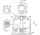
[0022] 図1は、本発明の一実施形態によるリソグラフィ装置を概略的に示したものである。この装置は、
− 放射ビームB(例えばUV放射又はDUV放射)を調節するように構成された照明システム(イルミネータ)ILと、
− パターニングデバイス(例えばマスク)MAを支持するように構築され、特定のパラメータに従ってパターニングデバイスを正確に位置決めするように構成された第1のポジショナPMに接続された支持構造(例えばマスクテーブル)MTと、
− 基板(例えばレジストコートウェーハ)Wを保持するように構築され、特定のパラメータに従って基板を正確に位置決めするように構成された第2のポジショナPWに接続された基板テーブル(例えばウェーハテーブル)WTと、
− パターニングデバイスMAによって放射ビームBに与えられたパターンを基板Wのターゲット部分C(例えば1つ又は複数のダイを含む)に投影するように構成された投影システム(例えば屈折投影レンズシステム)PSとを備える。
[0022] Figure 1 schematically depicts a lithographic apparatus according to one embodiment of the invention. This device
An illumination system (illuminator) IL configured to condition a radiation beam B (eg UV radiation or DUV radiation);
A support structure (eg mask table) MT constructed to support the patterning device (eg mask) MA and connected to a first positioner PM configured to accurately position the patterning device according to certain parameters; ,
A substrate table (eg wafer table) WT constructed to hold a substrate (eg resist-coated wafer) W and connected to a second positioner PW configured to accurately position the substrate according to certain parameters; ,
A projection system (eg a refractive projection lens system) PS configured to project a pattern imparted to the radiation beam B by the patterning device MA onto a target portion C (eg comprising one or more dies) of the substrate W; Is provided.
[0023] 照明システムは、放射の誘導、整形、又は制御を行うための、屈折型、反射型、磁気型、電磁型、静電型等の光学コンポーネント、又はその任意の組合せなどの種々のタイプの光学コンポーネントを含んでいてもよい。 [0023] The illumination system may be of various types, such as refractive, reflective, magnetic, electromagnetic, electrostatic, and other optical components, or any combination thereof, for directing, shaping, or controlling radiation. The optical component may be included.
[0024] 支持構造MTは、パターニングデバイスの方向、リソグラフィ装置の設計等の条件、例えばパターニングデバイスが真空環境で保持されているか否かに応じた方法で、パターニングデバイスを保持する。この支持構造は、パターニングデバイスを保持するために、機械式、真空式、静電式等のクランプ技術を使用することができる。支持構造は、例えばフレーム又はテーブルでよく、必要に応じて固定式又は可動式でよい。支持構造は、パターニングデバイスが例えば投影システムなどに対して確実に所望の位置に来るようにできる。本明細書において「レチクル」又は「マスク」という用語を使用した場合、その用語は、より一般的な用語である「パターニングデバイス」と同義と見なすことができる。 The support structure MT holds the patterning device in a manner that depends on the orientation of the patterning device, conditions such as the design of the lithographic apparatus, for example, whether or not the patterning device is held in a vacuum environment. The support structure can use mechanical, vacuum, electrostatic or other clamping techniques to hold the patterning device. The support structure may be a frame or a table, for example, and may be fixed or movable as required. The support structure may ensure that the patterning device is at a desired position, for example with respect to the projection system. Any use of the terms “reticle” or “mask” herein may be considered synonymous with the more general term “patterning device.”
[0025] 本明細書において使用する「パターニングデバイス」という用語は、基板のターゲット部分にパターンを生成するように、放射ビームの断面にパターンを与えるために使用し得る任意のデバイスを指すものとして広義に解釈されるべきである。ここで、放射ビームに与えられるパターンは、例えばパターンが位相シフトフィーチャ又はいわゆるアシストフィーチャを含む場合、基板のターゲット部分における所望のパターンに正確には対応しないことがある点に留意されたい。通常、放射ビームに与えられるパターンは、集積回路などのターゲット部分に生成されるデバイスの特定の機能層に相当する。 [0025] As used herein, the term "patterning device" is used broadly to refer to any device that can be used to pattern a cross-section of a radiation beam so as to generate a pattern on a target portion of a substrate. Should be interpreted. It should be noted here that the pattern imparted to the radiation beam may not exactly correspond to the desired pattern in the target portion of the substrate, for example if the pattern includes phase shift features or so-called assist features. Usually, the pattern imparted to the radiation beam corresponds to a particular functional layer in a device being created in the target portion, such as an integrated circuit.
[0026] パターニングデバイスは透過性又は反射性でよい。パターニングデバイスの例には、マスク、プログラマブルミラーアレイ、及びプログラマブルLCDパネルがある。マスクはリソグラフィにおいて周知のものであり、これには、バイナリマスク、レベンソン型(alternating)位相シフトマスク、ハーフトーン型(attenuated)位相シフトマスクのようなマスクタイプ、さらには様々なハイブリッドマスクタイプも含まれる。プログラマブルミラーアレイの一例として、小さなミラーのマトリクス配列を使用し、そのミラーは各々、入射する放射ビームを異なる方向に反射するよう個々に傾斜することができる。傾斜したミラーは、ミラーマトリクスによって反射する放射ビームにパターンを与える。 [0026] The patterning device may be transmissive or reflective. Examples of patterning devices include masks, programmable mirror arrays, and programmable LCD panels. Masks are well known in lithography, and include mask types such as binary masks, Levenson phase shift masks, attenuated phase shift masks, and various hybrid mask types. It is. As an example of a programmable mirror array, a matrix array of small mirrors is used, each of which can be individually tilted to reflect the incoming radiation beam in a different direction. The tilted mirror imparts a pattern to the radiation beam reflected by the mirror matrix.
[0027] 本明細書において使用する「投影システム」という用語は、使用する露光放射、又は液浸液の使用や真空の使用などの他の要因に合わせて適宜、例えば屈折型光学システム、反射型光学システム、反射屈折型光学システム、磁気型光学システム、電磁型光学システム及び静電型光学システム、又はその任意の組合せを含む任意のタイプの投影システムを包含するものとして広義に解釈されるべきである。本明細書において「投影レンズ」という用語を使用した場合、その用語はより一般的な用語である「投影システム」と同義と見なしてもよい。 [0027] As used herein, the term "projection system" refers to the exposure radiation used, or other factors such as the use of immersion liquid or vacuum, as appropriate, eg, refractive optical system, reflective type It should be construed broadly to encompass any type of projection system, including optical systems, catadioptric optical systems, magnetic optical systems, electromagnetic optical systems and electrostatic optical systems, or any combination thereof. is there. Any use of the term “projection lens” herein may be considered as synonymous with the more general term “projection system”.
[0028] 本明細書に示すように、本装置は透過タイプである(例えば透過マスクを使用する)。あるいは、装置は反射タイプでもよい(例えば上記で言及したようなタイプのプログラマブルミラーアレイを使用する、又は反射マスクを使用する)。 [0028] As shown herein, the apparatus is of a transmissive type (eg, using a transmissive mask). Alternatively, the device may be of a reflective type (for example using a programmable mirror array of the type mentioned above or using a reflective mask).
[0029] リソグラフィ装置は、例えば2つ以上の基板テーブル、又は1つ又は複数の基板テーブルと1つ又は複数のセンサ又は測定テーブルとの組合せのような2つ以上のテーブル(又はステージ又は支持体)を有するタイプでもよい。このような「マルチステージ」機械では、追加のテーブルを並行して使用してもよく、又は準備ステップを1つ又は複数のテーブル上で実行する一方で、1つ又は複数の別のテーブルを露光用に使用してもよい。リソグラフィ装置は、同様に基板、センサ、及び測定テーブルと並行して使用してもよい2つ以上のパターニングデバイス(又はステージ又は支持体)を有してもよい。 [0029] The lithographic apparatus may comprise two or more tables (or stages or supports) such as, for example, two or more substrate tables or a combination of one or more substrate tables and one or more sensors or measurement tables. ). In such “multi-stage” machines, additional tables may be used in parallel, or preparatory steps are performed on one or more tables while exposing one or more other tables. May be used for The lithographic apparatus may also have two or more patterning devices (or stages or supports) that may be used in parallel with the substrate, sensor, and measurement table.
[0030] リソグラフィ装置は、投影システムと基板との間の空間を充填するように、基板の少なくとも一部を水などの比較的高い屈折率を有する液体で覆えるタイプでもよい。液浸液は、例えばマスクと投影システムの間など、リソグラフィ装置の他の空間に適用することもできる。液浸技術は、投影システムの開口数を増加させるために当技術分野で周知である。本明細書で使用する「液浸」という用語は、基板などの構造を液体に沈めなければならないということをもっぱら意味するのではなく、露光中に投影システムと基板及び/又はパターニングデバイスとの間に液体が存在するというほどの意味である。これは液体に液浸される基板などの構造体を伴ってもよく、又は伴わなくてもよい。参照符号IMは、液浸技術を実装する装置を配置し得る場所を示す。このような装置は、液浸液の供給システムと、該当する領域に液体を含める液体閉じ込め構造とを含んでもよい。 [0030] The lithographic apparatus may be of a type wherein at least a portion of the substrate is covered with a liquid having a relatively high refractive index, such as water, so as to fill a space between the projection system and the substrate. An immersion liquid may also be applied to other spaces in the lithographic apparatus, for example, between the mask and the projection system. Immersion techniques are well known in the art for increasing the numerical aperture of projection systems. As used herein, the term “immersion” does not simply mean that a structure, such as a substrate, must be submerged in the liquid, but between the projection system and the substrate and / or patterning device during exposure. It means that there is liquid in This may or may not involve a structure such as a substrate that is immersed in the liquid. The reference sign IM indicates where an apparatus implementing the immersion technique can be placed. Such an apparatus may include an immersion liquid supply system and a liquid confinement structure that includes liquid in the area of interest.
[0031] 図1を参照すると、イルミネータILは放射源SOから放射ビームを受ける。放射源及びリソグラフィ装置は、例えば放射源がエキシマレーザである場合に、別々の構成素子であってもよい。このような場合、放射源はリソグラフィ装置の一部を形成すると見なされず、放射ビームは、例えば適切な誘導ミラー及び/又はビームエクスパンダなどを備えるビームデリバリシステムBDを用いて、放射源SOからイルミネータILへと渡される。他の事例では、例えば放射源が水銀ランプの場合は、放射源SOがリソグラフィ装置の一体部分であってもよい。放射源及びイルミネータILは、必要に応じてビームデリバリシステムBDとともに放射システムと呼ぶことができる。 [0031] Referring to FIG. 1, the illuminator IL receives a radiation beam from a radiation source SO. The source and the lithographic apparatus may be separate components, for example when the source is an excimer laser. In such a case, the radiation source is not considered to form part of the lithographic apparatus, and the radiation beam is emitted from the source SO by means of a beam delivery system BD, for example comprising a suitable guiding mirror and / or beam expander. Passed to IL. In other cases the source SO may be an integral part of the lithographic apparatus, for example when the source is a mercury lamp. The radiation source and illuminator IL may be referred to as a radiation system with a beam delivery system BD as required.
[0032] イルミネータILは、放射ビームの角度強度分布を調整するアジャスタADを備えてもよい。通常、イルミネータの瞳面における強度分布の少なくとも外側及び/又は内側半径範囲(通例それぞれ、σ-outer及びσ-innerと呼ばれる)を調整することができる。さらに、イルミネータILは、インテグレータIN、コンデンサCOなどの他の種々のコンポーネントを備えてもよい。イルミネータを用いて放射ビームを調節し、その断面にわたって所望の均一性と強度分布とが得られるようにしてもよい。 [0032] The illuminator IL may include an adjuster AD for adjusting the angular intensity distribution of the radiation beam. Typically, at least the outer and / or inner radius ranges (commonly referred to as σ-outer and σ-inner, respectively) of the intensity distribution at the illuminator pupil plane can be adjusted. Further, the illuminator IL may include other various components such as an integrator IN and a capacitor CO. An illuminator may be used to adjust the radiation beam to obtain the desired uniformity and intensity distribution across its cross section.
[0033] 放射ビームBは、支持構造(例えば、マスクテーブル)MT上に保持されたパターニングデバイス(例えば、マスク)MAに入射し、パターニングデバイスによってパターニングされる。パターニングデバイスMAを横断した放射ビームBは、投影システムPSを通過し、投影システムPSは、ビームを基板Wのターゲット部分C上に合焦させる。第2のポジショナPWと位置センサIF(例えば、干渉計デバイス、リニアエンコーダ又は容量センサ)を用いて、基板テーブルWTは、例えば、様々なターゲット部分Cを放射ビームBの経路に位置決めできるように正確に移動できる。同様に、第1のポジショナPMと別の位置センサ(図1には明示されていない)を用いて、マスクライブラリからの機械的な取り出し後又はスキャン中などに放射ビームBの経路に対してパターニングデバイスMAを正確に位置決めできる。通常、支持構造MTの移動は、第1のポジショナPMの部分を形成するロングストロークモジュール(粗動位置決め)及びショートストロークモジュール(微動位置決め)を用いて実現できる。同様に、基板テーブルWTの移動は、第2のポジショナPWの部分を形成するロングストロークモジュール及びショートストロークモジュールを用いて実現できる。ステッパの場合(スキャナとは対照的に)、支持構造MTをショートストロークアクチュエータのみに接続するか、又は固定してもよい。パターニングデバイスMA及び基板Wは、パターニングデバイスアライメントマークM1、M2及び基板アライメントマークP1、P2を使用して位置合わせすることができる。図示のような基板アライメントマークは、専用のターゲット部分を占有するが、ターゲット部分の間の空間に位置してもよい(スクライブレーンアライメントマークとして知られている)。同様に、パターニングデバイスMA上に複数のダイを設ける状況では、パターニングデバイスアライメントマークをダイ間に配置してもよい。 [0033] The radiation beam B is incident on the patterning device (eg, mask) MA, which is held on the support structure (eg, mask table) MT, and is patterned by the patterning device. The radiation beam B traversing the patterning device MA passes through the projection system PS, which focuses the beam onto the target portion C of the substrate W. Using the second positioner PW and the position sensor IF (eg interferometer device, linear encoder or capacitive sensor), the substrate table WT is accurate so that, for example, various target portions C can be positioned in the path of the radiation beam B. Can move to. Similarly, patterning with respect to the path of the radiation beam B using a first positioner PM and another position sensor (not explicitly shown in FIG. 1) after mechanical removal from the mask library or during a scan. The device MA can be accurately positioned. In general, the movement of the support structure MT can be realized by using a long stroke module (coarse positioning) and a short stroke module (fine positioning) that form a portion of the first positioner PM. Similarly, the movement of the substrate table WT can be realized using a long stroke module and a short stroke module that form part of the second positioner PW. In the case of a stepper (as opposed to a scanner) the support structure MT may be connected to a short stroke actuator only, or may be fixed. Patterning device MA and substrate W may be aligned using patterning device alignment marks M1, M2 and substrate alignment marks P1, P2. The substrate alignment mark as shown occupies a dedicated target portion, but may be located in the space between the target portions (known as a scribe lane alignment mark). Similarly, in situations where multiple dies are provided on the patterning device MA, patterning device alignment marks may be placed between the dies.
[0034] 図示のリソグラフィ装置は、以下のモードのうち少なくとも1つにて使用可能である。
1.ステップモードにおいては、支持構造MT及び基板テーブルWTは、基本的に静止状態に維持される一方、放射ビームに与えたパターン全体が1回でターゲット部分Cに投影される(すなわち単一静的露光)。次に、別のターゲット部分Cを露光できるように、基板テーブルWTがX方向及び/又はY方向に移動される。ステップモードでは、露光フィールドの最大サイズによって、単一静的露光で像が形成されるターゲット部分Cのサイズが制限される。
2.スキャンモードにおいては、支持構造MT及び基板テーブルWTは同期的にスキャンされる一方、放射ビームに与えられるパターンがターゲット部分Cに投影される(すなわち単一動的露光)。支持構造MTに対する基板テーブルWTの速度及び方向は、投影システムPSの拡大(縮小)及び像反転特性によって求めることができる。スキャンモードでは、露光フィールドの最大サイズによって、単一動的露光におけるターゲット部分の(非スキャン方向における)幅が制限され、スキャン動作の長さによってターゲット部分の(スキャン方向における)高さが決まる。
3.別のモードでは、支持構造MTはプログラマブルパターニングデバイスを保持して基本的に静止状態に維持され、基板テーブルWTを移動又はスキャンさせながら、放射ビームに与えられたパターンをターゲット部分Cに投影する。このモードでは、一般にパルス状放射源を使用して、基板テーブルWTを移動させる毎に、又はスキャン中に連続する放射パルスの間で、プログラマブルパターニングデバイスを必要に応じて更新する。この動作モードは、以上で言及したようなタイプのプログラマブルミラーアレイなどのプログラマブルパターニングデバイスを使用するマスクレスリソグラフィに容易に利用できる。
The illustrated lithographic apparatus can be used in at least one of the following modes:
1. In step mode, the support structure MT and the substrate table WT are basically kept stationary, while the entire pattern imparted to the radiation beam is projected onto the target portion C at one time (ie a single static exposure). ). Next, the substrate table WT is moved in the X and / or Y direction so that another target portion C can be exposed. In step mode, the maximum size of the exposure field limits the size of the target portion C on which an image is formed with a single static exposure.
2. In scan mode, the support structure MT and the substrate table WT are scanned synchronously while a pattern imparted to the radiation beam is projected onto a target portion C (ie, a single dynamic exposure). The speed and direction of the substrate table WT relative to the support structure MT can be determined by the enlargement (reduction) and image reversal characteristics of the projection system PS. In scan mode, the maximum size of the exposure field limits the width of the target portion (in the non-scan direction) in a single dynamic exposure, and the length of the scan operation determines the height of the target portion (in the scan direction).
3. In another mode, the support structure MT is held essentially stationary while holding the programmable patterning device, and projects the pattern imparted to the radiation beam onto the target portion C while moving or scanning the substrate table WT. In this mode, a pulsed radiation source is typically used to update the programmable patterning device as needed each time the substrate table WT is moved or between successive radiation pulses during a scan. This mode of operation can be readily applied to maskless lithography that utilizes programmable patterning device, such as a programmable mirror array of a type as referred to above.
[0035] 上述した使用モードの組合せ及び/又は変形、又は全く異なる使用モードも利用できる。 [0035] Combinations and / or variations on the above described modes of use or entirely different modes of use may also be employed.
[0036] 上述のように、レンズ鏡筒内の内部ガス環境と投影システム外部の環境(例えば「クリーンルーム」、以下通常、外部環境と言う)との間の圧力差の変化は、基板上に形成される像の精度を低下させることがある。光学的精度の低下は、(例えば個々のレンズであってよい)光学素子にわたる圧力差において結果として生じる変化に起因して生じ得る。光学素子にわたる圧力差の変化は、光学素子の歪み及び/又は変位、及びそれに対応した投影システムの光学的性能の変化をもたらし得る。素子圧力差の変化は、一方の側が外部環境の圧力に曝され、他方の側が外部環境から実質的に隔絶された内部ガス環境に曝される投影システムの最上端及び/又は最下端における光学素子についてより一層大きいことがある。外部環境での圧力は極めて大幅に且つ比較的短い時間スケールで変化し得る。例えば、外部環境におけるドア閉めは、正確な圧力変動の大きさは外部環境のサイズ、ドアの性質や位置、ドアが閉じられる方法などを含む多くの要因に左右されるが、概してリソグラフィ装置にて25Paに及ぶ圧力変動を引き起こすことがある。内部ガス環境を通す継続的なガスの流れが提供されてもよい。継続的なガスの流れは、例えばガス放出に起因する汚染物質を除去するのに有益であり得る。典型的にはガスの流れは、それが極めて効果的であるには内部ガス環境の容積と比較してあまりに少ないであろうものの、ガスの流れは、内部ガス環境の近傍の光学素子内の加熱を制御するのにも役立つことがある。基本的には、ガスの流入及び/又は流出は、全体的な圧力を制御するよう調整できる。しかし、このようなシステムにとって、外部環境に由来する圧力変動を効果的に補償するように十分に迅速に応答することは困難である。 [0036] As described above, a change in pressure difference between the internal gas environment in the lens barrel and the environment outside the projection system (for example, "clean room", hereinafter usually referred to as the external environment) is formed on the substrate. The accuracy of the resulting image may be reduced. The loss of optical accuracy can occur due to the resulting change in pressure differential across the optical element (which can be, for example, an individual lens). Changes in the pressure differential across the optical element can result in distortion and / or displacement of the optical element and corresponding changes in the optical performance of the projection system. The change in element pressure differential is due to the optical elements at the top and / or bottom end of the projection system where one side is exposed to the pressure of the external environment and the other side is exposed to an internal gas environment substantially isolated from the external environment. May be even greater. The pressure in the external environment can vary very significantly and on a relatively short time scale. For example, the door closure in the external environment depends on many factors, including the size of the external environment, the nature and position of the door, the way the door is closed, etc. May cause pressure fluctuations up to 25 Pa. A continuous gas flow through the internal gas environment may be provided. A continuous gas flow can be beneficial, for example, in removing contaminants due to outgassing. Typically, the gas flow will be too small compared to the volume of the internal gas environment for it to be very effective, but the gas flow is not heated in the optical element in the vicinity of the internal gas environment. It can also help to control. Basically, gas inflow and / or outflow can be adjusted to control the overall pressure. However, it is difficult for such a system to respond quickly enough to effectively compensate for pressure fluctuations originating from the external environment.
[0037] 以下の記載では、「外部ガス環境」と言う用語は、外部環境から実質的に隔絶(言い換えると密閉)されず、したがって外部環境(例えば、クリーンルーム)と実質的に同じ圧力(すなわち、ほぼ大気圧)に保たれるいずれかの容積を指すために用いられる。したがって、外部ガス環境は、リソグラフィ装置の外側の環境に「接続している」と見なしてもよい。この文脈では、それ故、外部ガス環境はリソグラフィ装置内部に存在し得る。これに対して、「内部ガス環境」は、外部環境から実質的に隔絶された容積を指す。「実質的に隔絶された」と言う用語は、この文脈では、独立した圧力調整が可能な程度に隔絶されることを意味する。したがって、内部ガス環境が外部ガス環境から実質的に隔絶されると言うことは、(外部ガス環境の圧力変化に応じて内部ガス環境内の圧力を調整する周到な手段がない場合)内部ガス環境内の圧力が外部ガス環境の圧力から実質的に独立していることを意味する。したがって、内部ガス環境内の圧力は、外部ガス環境の圧力とは実質的に異なるレベルに保つことができる。通常、内部ガス環境内の圧力は、必ずしも不可欠ではないが、外部ガス環境の呼び圧力よりも高いレベルに保たれる。内部ガス環境内の圧力は、外部ガス環境の呼び圧力と実質的に同じレベル、又はそれ以下のレベルに保たれてもよい。 [0037] In the following description, the term "external gas environment" is not substantially isolated (in other words, sealed) from the external environment, and is therefore substantially the same pressure (ie, clean room) (ie, a clean room). Used to refer to any volume that is maintained at about atmospheric pressure. Thus, the external gas environment may be considered “connected” to the environment outside the lithographic apparatus. In this context, therefore, an external gas environment can exist inside the lithographic apparatus. In contrast, an “internal gas environment” refers to a volume that is substantially isolated from the external environment. The term “substantially isolated” in this context means isolated to the extent that independent pressure regulation is possible. Thus, the internal gas environment is substantially isolated from the external gas environment (if there is no meticulous means of adjusting the pressure in the internal gas environment in response to pressure changes in the external gas environment). It means that the internal pressure is substantially independent of the pressure of the external gas environment. Thus, the pressure in the internal gas environment can be maintained at a level that is substantially different from the pressure in the external gas environment. Usually, the pressure in the internal gas environment is not necessarily essential, but is maintained at a level higher than the nominal pressure of the external gas environment. The pressure within the internal gas environment may be maintained at a level substantially equal to or less than the nominal pressure of the external gas environment.
[0038] 内部ガス環境は、投影システムの上部に存在してもよい。この場合、内部ガス環境は、第1の光学素子(すなわち、パターニングされた放射ビームが当たる投影システムの第1の光学素子)と、隣接する光学素子(「第2の」光学素子)との間にあることになろう。しかし、本発明の実施形態は、追加として、又は代替として(投影システムの下端部に位置する)投影システムの最後の素子に応用できる。この場合、「内部ガス環境」は、最後の光学素子と最後から二番目の光学素子との間の領域であろう。液浸システムでは、最後の光学素子は、使用時に露光中、投影システムと基板との間に位置する液浸液と接触するであろう光学素子であろう。本発明の実施形態は、追加として、又は代替として投影システムの別の素子、又は別の光学系(例えば照明システム)に応用してもよい。 [0038] An internal gas environment may be present at the top of the projection system. In this case, the internal gas environment is between the first optical element (ie, the first optical element of the projection system that is subjected to the patterned radiation beam) and the adjacent optical element (the “second” optical element). It will be in. However, embodiments of the invention can be applied to the last element of the projection system (located at the lower end of the projection system) in addition or as an alternative. In this case, the “internal gas environment” would be the area between the last optical element and the penultimate optical element. In an immersion system, the last optical element will be the optical element that will be in contact with the immersion liquid located between the projection system and the substrate during exposure during use. Embodiments of the present invention may additionally or alternatively be applied to another element of the projection system, or to another optical system (eg, an illumination system).
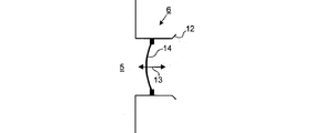
[0039] 図2は、投影システムの上部又は下部を示すものと見なしてもよい。図2を投影システムの上部を表すものと見なす場合は、図2の上部(すなわち、素子2)は図2の下部(すなわち、素子4)よりも高いと見なされる。図2が投影システムの下部を表すものと見なす場合は、図2の上部(すなわち、素子2)は図2の下部(すなわち、素子4)よりも低いと見なされる。図2が投影システムの上部を示すものと見なされる場合は、図示した部分は、外部ガス環境に曝される第1の面1と、外部ガス環境から実質的に隔絶され、その代わりに(能動的及び/又は受動的に)制御された内部ガス環境5に曝される第2の面3とを有する光学素子2(図2が投影システムの上部を示すと見なされる場合は「第1の光学素子」、又は図2が投影システムの下部を示すと見なされる場合は「最後の光学素子」)から構成されている。光学素子2は、通常それにかかる圧力の変動によって著しく変形しないほど十分に剛性となるレンズ鏡筒内に収容されている。光学素子2と隣接の光学素子4との間の領域が内部ガス環境を画定する。
[0039] FIG. 2 may be viewed as showing the top or bottom of the projection system. If FIG. 2 is considered to represent the top of the projection system, the top of FIG. 2 (ie, element 2) is considered higher than the bottom of FIG. 2 (ie, element 4). If FIG. 2 is considered to represent the bottom of the projection system, the top of FIG. 2 (ie, element 2) is considered lower than the bottom of FIG. 2 (ie, element 4). If FIG. 2 is considered to show the top of the projection system, the illustrated part is substantially isolated from the first surface 1 exposed to the external gas environment, and instead of (active)
[0040] 開示する実施形態によれば、外部ガス環境の圧力変化に応じて内部ガス環境内の圧力を調整するために、圧力補償システムが提供される。圧力補償システムは、光学素子2にわたって結果として生じる圧力差の変化を低減するように、外部ガス環境の圧力差の変化に反応する。
[0040] According to the disclosed embodiments, a pressure compensation system is provided for adjusting the pressure in the internal gas environment in response to pressure changes in the external gas environment. The pressure compensation system is responsive to changes in the pressure difference of the external gas environment so as to reduce the resulting pressure difference change across the
[0041] 図2から図7に示す実施形態では、内部ガス環境の容積を調整するために、容積アジャスタ6が設けられる。容積アジャスタ6は、外部ガス環境の圧力上昇に応じて内部ガス環境の容積を縮小し、外部ガス環境の圧力の圧力降下に応じて内部ガス環境の容積を増大し、又はその両方を行うように構成されている。 In the embodiment shown in FIGS. 2 to 7, a volume adjuster 6 is provided to adjust the volume of the internal gas environment. The volume adjuster 6 reduces the volume of the internal gas environment according to the pressure increase of the external gas environment, increases the volume of the internal gas environment according to the pressure drop of the pressure of the external gas environment, or both. It is configured.
[0042] 図2から図4では、容積アジャスタは、外部ガス環境の圧力変化に受動的に応答するように構成されたコンポーネントを備えている。受動コンポーネントは、外部電源又は能動制御システムを必要とせずに応答する。 [0042] In FIGS. 2-4, the volume adjuster includes components configured to passively respond to pressure changes in the external gas environment. Passive components respond without the need for an external power supply or active control system.
[0043] 図5から図7では、容積アジャスタは、内部ガス環境の容積を能動的に変更するように構成されたコンポーネントを備えている。能動コンポーネントは、電源及び制御システム(コントローラ)に依存する機構を備えている。 [0043] In FIGS. 5-7, the volume adjuster comprises a component configured to actively change the volume of the internal gas environment. The active component comprises a mechanism that depends on the power source and the control system (controller).
[0044] 図2では、受動コンポーネントは、シリンダ9内で移動可能な(矢印11)ピストン8を備えている。ピストン8の断面形状は(円形であってもよいが、別の形状のものを使用してもよい)シリンダ9の内部断面形状に対応する。ガスがピストン8を越えて漏れることを防止するか又は最小限にするため、ピストン8とシリンダ9との間に摺動シール10が設けられている。シリンダ9は、一端が内部ガス環境に、他端が開口12に接続されてもよい。開口12は、外部ガス環境に接続する空間に連通している。システムは、外部ガス環境の圧力上昇がピストン8を内側(図の左側)に移動させ、それにより内部ガス環境の容積を縮小させ且つその内部の圧力の補償上昇を生じさせるように、構成されている。外部ガス環境の圧力低下は、ピストン8が外側(図の右側)に押されるようにし、それにより内部ガス環境の容積を増大させ且つその内部の圧力の補償低下を生じさせるように構成されている。両方の場合とも、その効果は、外部ガス環境内の圧力変動によって生じる光学素子2にわたる圧力差の変化の大きさを低減することである。内部ガス環境内の圧力が外部ガス環境の圧力よりも高いレベルの圧力に保たれる場合は、ピストン8には、ピストン8を内部ガス環境の内側に向かって付勢する弾性部材(図示せず)が設けられるであろう。付勢力は、ピストン8にわたる呼び圧力差を平衡するために必要である。内部ガス環境内の圧力が外部ガス環境の圧力よりも低いレベルに保たれる場合は、ピストン8には、ピストンを内部ガス環境の外側に向かって付勢する弾性部材(図示せず)が設けられるであろう。
In FIG. 2, the passive component comprises a piston 8 that is movable in the cylinder 9 (arrow 11). The cross-sectional shape of the piston 8 corresponds to the internal cross-sectional shape of the cylinder 9 (which may be circular but may be of another shape). A sliding
[0045] ピストン8の縦軸は、内部ガス環境から離れるように傾斜して下方に向けられてもよい。こうすれば、移動するピストンに関連する汚染物質が内部ガス環境内の重要な素子から離れやすいであろう。 [0045] The longitudinal axis of the piston 8 may be inclined downward and away from the internal gas environment. In this way, contaminants associated with the moving piston will be likely to leave important elements in the internal gas environment.
[0046] 図3は、受動コンポーネントが、外部ガス環境の圧力変動に応じて内側、外側、又は内側及び外側(矢印13)に変形するように構成された変形可能部材14(この例ではメンブレン)を備える、実施形態を示す。図3のアレンジの動作は、図2の実施形態のピストン8及びシリンダ9の動作に対応する。しかし、内部ガス環境5の容積の変化は、変位によってではなく変形によって達成される。図3のアレンジは、移動部品が最小限に抑えられるので有利である。このようにして内部ガス環境5の汚染のリスクが低減される。変形可能部材14とレンズ鏡筒5との間の連結ポイントは固定され、これが信頼できるシールを設けるのに役立つ。変形可能部材として、例えばポリテトラフルオロエチレン(PTFE)メンブレンが使用されてもよい。湿気の流れがメンブレンを通ることを防止するため、メンブレンの領域に乾燥パージガス流が供給されてもよい。内部ガス環境5内の圧力が外部ガス環境の圧力よりも高いレベル又は低いレベルに保たれる場合は、必要な付勢を与えるために変形可能部材14にはまた弾性部材(図示せず)が設けられてもよい。例えば、変形可能部材14は弾性特性を有するメンブレンから形成されてよい。
[0046] FIG. 3 shows a deformable member 14 (in this example a membrane) configured such that the passive component deforms inward, outward, or inward and outward (arrow 13) in response to pressure fluctuations in the external gas environment. An embodiment comprising The operation of the arrangement of FIG. 3 corresponds to the operation of the piston 8 and the cylinder 9 of the embodiment of FIG. However, the change in volume of the
[0047] 図4は、受動コンポーネントが外部ガス環境の圧力変動に応じて形状が変化する(矢印15)ように構成されたベローズを備える実施形態を示す。ベローズの動作は、両者とも上で説明されたピストン8及びシリンダ9のアレンジ、及び変形可能部材14のアレンジの動作に対応する。ベローズ16は、外部ガス環境の圧力変動に応じて内側、外側、又は内側及び外側(矢印15)に駆動されるように構成されている。ベローズ16は実際には、外部ガス環境の圧力変動によって駆動されて、変動を少なくとも部分的に補償するように内部ガス環境5の容積を変化させる。外部ガス環境の圧力上昇は内部ガス環境5の容積の対応する増大を伴い、逆の場合も同様である。図3の変形可能部材14のアレンジの場合と同様に、ベローズ16は、移動部品が最小限に抑えられる(例えば摺動シールは必要ない)ので有利である。粒子の形成は望ましく最小限に抑えられる。内部ガス環境5内の圧力を外部ガス環境の圧力よりも高いレベル、又は低いレベルに保つ場合は、図2及び図3を参照して上で説明された実施形態と同様に、必要な付勢を与えるようベローズ16に弾性部材が設けられる。
[0047] FIG. 4 illustrates an embodiment in which the passive component comprises a bellows configured to change shape (arrow 15) in response to pressure fluctuations in the external gas environment. Both of the bellows actions correspond to the arrangement of the piston 8 and the cylinder 9 and the arrangement of the
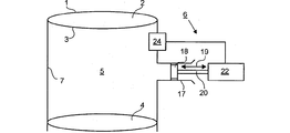
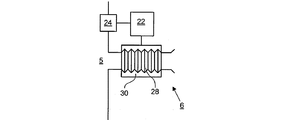
[0048] 図5から図7は、図2から図4の実施形態にそれぞれ対応する。図2から図4の実施形態の受動コンポーネントが、図2から図4に示すアレンジにあるコンポーネントに対応するものでよい1つ又は複数の能動コンポーネントに置き換えられている。各アレンジのシステムには、圧力センサシステム24が備えられている。圧力センサシステム24は、以下のうちの、すなわち(例えば外部ガス環境の圧力センサを介した)外部ガス環境内の圧力、(例えば内部ガス環境5内の圧力センサを介した)内部ガス環境5内の圧力、及び/又は(例えば内部ガス環境と外部ガス環境との間の境界に位置する圧力差センサを介した)内部ガス環境5と外部ガス環境との間の圧力差のうちの1つ又は複数の値を測定するように構成されている。圧力センサシステム24から入力を受けるコントローラ22が備えられている。コントローラ22は、外部ガス環境内の測定された圧力だけに応答するように構成されてもよい。例えば、コントローラ22は、外部ガス環境内の検出された圧力変化に対応する量だけ内部ガス容量内の圧力を調整するように構成されてもよい。代替的に又は追加的に、コントローラ22は、(内部ガス環境及び外部ガス環境の各々の内部の別個のセンサを介した)内部ガス環境及び外部ガス環境内の圧力の別個の測定から導き出される内部ガス環境5と外部ガス環境との間の圧力差に応答するように構成されてもよい。例えば、コントローラ22は、内部ガス環境内の圧力と外部ガス環境内の圧力との差の検出された変化に対応する量だけ、内部ガス容積内の圧力を調整するように構成されてもよい。代替的に又は追加的に、コントローラ22は、圧力差センサを介して圧力差を直接測定することから導き出された内部と外部のガス環境の圧力差に応答するように構成されてもよい。例えば、コントローラ22は、検出された圧力差の検出された変化に対応する量だけ内部ガス容積内の圧力を調整するように構成されてもよい。
FIGS. 5 to 7 correspond to the embodiments of FIGS. 2 to 4, respectively. The passive components of the embodiment of FIGS. 2-4 have been replaced with one or more active components that may correspond to the components in the arrangement shown in FIGS. Each arrangement system is provided with a
[0049] 図5では、ピストン18とシリンダ17とが、ピストン18の内側及び外側への運動(矢印19)を駆動するように構成されたピストンドライバ20と協動する。ピストンドライバ20は、コントローラ22からの制御信号に応答してピストン18を駆動する。制御信号は、(圧力センサシステム24によって測定された)外部ガス環境の圧力変動を少なくとも部分的に補償する方向にピストン18を移動させるような信号である。例えば、外部ガス環境内の圧力が上昇すると、制御信号は、ピストンドライバ20がピストン18を内側に(図の左側に)駆動させるような信号になる。外部ガス環境内の圧力が低下すると、制御信号は、ピストンドライバ20がピストン18を外側に(図の右側に)駆動させるような信号になる。コントローラ22は、例えばフィードバックアレンジメントで動作するように構成されてもよい。追加的に又は代替的に、コントローラ22は、フィードフォワード制御を使用するように構成されてもよい。ピストン18の縦軸は、内部ガス環境5から離れるよう傾斜して下方に向けられてもよい。こうすれば、移動するピストン18に関連する汚染物質が内部ガス環境5内の重要な素子から離れやすいであろう。
In FIG. 5, the
[0050] 図6では、変形可能部材26が変形可能部材ドライバ25と協動する。変形可能部材ドライバ25は、コントローラ22からの制御信号に基づいて変形状態(矢印21)を制御するように構成される。例えば、外部ガス環境内の圧力が上昇すると、制御信号は、内部ガス環境5の容積が縮小するように、変形可能部材ドライバ25が変形可能部材26を変形させるような信号になる。外部ガス環境の圧力が低下すると、制御信号は、内部ガス環境5の容積が増大するように変形可能部材26を変形させるような信号になる。
In FIG. 6, the
[0051] 図7では、ベローズ28には、コントローラ22からの制御信号に基づいてベローズ28の容積を制御するように構成されたベローズドライバ30が設けられている。例えば、外部ガス環境の圧力が上昇すると、制御信号は、ベローズドライバ30がベローズ28に内部ガス環境の容積を低減させるような信号になる。外部ガス圧力が低下すると、制御信号は、ベローズ28が内部ガス環境の容積を増大させるような信号になる。
In FIG. 7, the
[0052] 図2から図7のピストン及びシリンダ、メンブレン又はベローズなどの変形可能部材、又はそのいずれかの一部を分離して、又はいずれかの組合せで一緒に使用してもよい。さらに、内部ガス環境5が実質的に静止ガスを含んでいる場合が図示されているが、必ずしもそうである必要はない。例えば、内部ガス環境5を通して連続的なガス流を供給するためにパージガス供給システムが提供されてもよい。
[0052] The deformable member, such as the piston and cylinder, membrane or bellows of FIGS. 2-7, or any portion thereof, may be used separately or together in any combination. Furthermore, although the case where the
[0053] 追加的に又は代替的に、圧力補償システムは、内部ガス環境5内のガス粒子の数(すなわち、内部ガス環境内のガス量)を調整するガス粒子アジャスタを備えてもよい。内部ガス環境5内の圧力は、ガス粒子数を増大させることによって上昇させることができる。内部ガス環境5内の圧力は、ガス粒子数を減少させることによって低下させることができる。内部ガス環境5内の圧力を操作するこの方法は、内部ガス環境5の容積変化に基づいて、単独で、又は上記の実施形態のいずれか1つ又は複数の組合せでも使用できる。
[0053] Additionally or alternatively, the pressure compensation system may include a gas particle adjuster that adjusts the number of gas particles in the internal gas environment 5 (ie, the amount of gas in the internal gas environment). The pressure in the
[0054] ガス粒子数の調整は、内部ガス環境5内の圧力とは異なる圧力でガスを収容するように構成された1つ又は複数のリザーバによって実施することができる。このようなリザーバを内部ガス環境に接続することは、内部ガス環境5内への、又は内部ガス環境5からのガスの正味流れをもたらすことになる。リザーバ内の圧力が内部ガス環境5内の圧力よりも高い場合は、ガスの正味流れは内部ガス環境5内への流れになる。内部ガス環境5内へのガスの正味流れは、内部ガス環境5内の圧力を上昇させやすい。リザーバ内の圧力が内部ガス環境5内の圧力よりも低い場合は、ガスの正味流れは内部ガス環境5から出る流れになる。内部ガス環境5から出るガスの正味流れは、内部ガス環境5内の圧力を低下させやすい。したがって、内部ガス環境5とは異なる圧力下にあるリザーバへの接続を選択的に制御することによって、内部ガス環境5内への、又は内部ガス環境5からのガスの流れを制御又は調整することができる。
The adjustment of the number of gas particles can be performed by one or more reservoirs configured to contain the gas at a pressure different from the pressure in the
[0055] 制御又は調整は、例えば、リザーバと内部ガス環境5との間の直接接続を介して、直接行うことができる。代替的に又は追加的に、制御又は調整は、内部ガス環境5に、又は内部ガス環境5に連通している供給管への接続を介して、間接的に行うことができる。供給管は、例えば内部ガス環境5を通してパージガス流を供給するパージガス供給システムに関連付けられた供給管であってよい。内部ガス環境5の圧力以下の圧力でガスを収容するように構成されたリザーバを「低圧リザーバ」と呼んでもよい。内部ガス環境5の圧力以上の圧力でガスを収容するように構成されたリザーバを「高圧リザーバ」と呼んでもよい。ある場合に低圧リザーバであるリザーバが、別の場合には高圧リザーバであってもよい。低圧リザーバと高圧リザーバは異なるものである必要はない。例えば、リザーバは、内部ガス環境5から流出する正味ガス流を生成する目的で、ある瞬間には低下された圧力を有してもよく、したがって低圧リザーバであると特徴付けられてもよい。別の瞬間には、同じリザーバが内部ガス環境5内に流入する正味ガス流を生成する目的で高圧を有してもよく、したがって高圧リザーバであると特徴付けられてもよい。リザーバは、例えば、交互順などの順番に低圧機能と高圧機能の両方を果たすことができる。
[0055] The control or adjustment can be made directly, for example, via a direct connection between the reservoir and the
[0056] 図8は、投影システムの上部又は下部に適用される例示的アレンジを示す。投影システムの上部又は下部の性質は図2を参照して上述した。図2から図7を参照して説明した実施形態と同様に、レンズ鏡筒7内に収納された、外部ガス環境に曝される第1の面と、内部ガス環境5に曝される第2の面3とを有する光学素子が設けられている。この例では、内部ガス環境5を通してガス流を供給するために、パージガス供給システムが提供される。ガス流は、例えば、内部ガス環境5から放出される汚染物質を除去するために利用できる。ガス流は、連続的なものでも、準連続的(すなわち、断続的にある期間にはオンで、ある期間にはオフ)なものでもよい。
[0056] FIG. 8 shows an exemplary arrangement applied to the top or bottom of the projection system. The upper or lower nature of the projection system has been described above with reference to FIG. Similar to the embodiment described with reference to FIGS. 2 to 7, the first surface exposed to the external gas environment and the second surface exposed to the
[0057] パージガス供給システムは、供給源36から入力ガスコントローラ32及び入力管40を経て内部ガス環境5にガスを供給し、出力管42及び出力ガスコントローラ34を経てシンク38にガスを引き出す。引き出しは能動的でも受動的でもよい。
The purge gas supply system supplies gas from the
[0058] この例では、ガス粒子アジャスタは、2つの低圧リザーバ46及び48と、2つの高圧リザーバ50及び52とを備えている。各リザーバ46、48、50、52はバルブ61、63、65、67を介して供給管44に接続されている。供給管44は内部ガス環境5に連通している。
In this example, the gas particle adjuster includes two
[0059] 低圧リザーバ46、48は、内部ガス環境5の圧力よりも低い圧力、望ましくは真空に近い圧力、例えば絶対圧力が0.1バール未満に保たれる。このようにして、バルブ61、63を開けると、ガスが内部ガス環境5から流出し、又は供給されたガス流が低圧リザーバ46、48の一方又は両方に再流入する。したがって、内部ガス環境5内のガス粒子数が、それ故圧力が減る。バルブ49、51を介してガスシンク56への低圧リザーバ46、48内の圧力を選択的に低下させるために、負圧源47が備えられる。
[0059] The
[0060] 高圧リザーバ50、52は、内部ガス環境5の圧力よりも高い圧力に保たれる。このようにして、バルブ65又は67を開けると、ガスが内部ガス環境5内に流入し、したがって、内部ガス環境5内の圧ガス粒子数が、それ故圧力が増える。バルブ53及び55を介してガス源58からの高圧リザーバ50、52内の圧力を選択的に上昇させるために、過圧源51が備えられる。ガス源58は、図に示し用に供給源36から導出してもよく、又は別個の供給源から導出してもよい。
The
[0061] 低圧又は高圧リザーバ46、48、50、52から内部ガス環境5内への、又は内部ガス環境5から出るガスの流量は、リザーバ46、48、50、52と内部ガス環境5との間の圧力差に左右される。リザーバ46、48、50、52と内部ガス環境5との間の圧力差を増大させる範囲は、低圧リザーバ46、48に関しては制限される。この制限が生ずるのは、(低圧リザーバ46、48内の絶対圧力を負にすることはできないので)圧力差が内部ガス環境5内の圧力を超えることができないからである。しかし、低圧リザーバ46、48の容積をより大きくして、これらのリザーバが内部ガス環境5に接続されるときにリザーバ内の圧力上昇率が低下するようにすることによって、この問題点を緩和することができる。高圧リザーバの場合は、圧力差は低圧リザーバの場合よりも大幅に大きくすることができる。したがって高圧リザーバをより小型にすることができる。通常、高圧リザーバを小型化することが望ましいが、それはリザーバを内部ガス環境5のできるだけ近傍に配置することが有利であり、且つこの領域のスペースが限られているからである。
[0061] The flow rate of the gas into or out of the
[0062] 圧力センサシステム24の検出値に応じてバルブ61、63、65、67の開放を制御するために、コントローラ60が設けられている。外部圧力が上昇すると、コントローラ60は高圧リザーバに連通しているバルブ65、67の一方又は両方を開く。高圧リザーバに連通しているバルブ65、67の一方又は両方が開かれると、内部ガス環境5内の圧力が上昇する。外部圧力が低下すると、コントローラ60は低圧リザーバに連通しているバルブ61、63の一方又は両方を開く。低圧リザーバに連通しているバルブ61、63の一方又は両方が開かれると、内部ガス環境5内の圧力が低下する。この例のコントローラ60は、また、リザーバ内の圧力を確実に使用可能状態の所望の開始値にするようにバルブ49、51、53及び55を制御するようにも構成されている。
[0062] A
[0063] この例では、複数の低圧リザーバ46、48が設けられている。これにより、リザーバ46、48の一方又は両方を選択的に開くことによって内部ガス環境5からガスを引き出す流量(及び/又は引き出されるガスの総量)を変更することが可能になる。代替的に又は追加的に、複数のリザーバがあることによって、内部ガス環境5内の圧力を調整するために別のリザーバを使用しながら、1つのリザーバ内の圧力を開始値の方に再び低下させることが可能になる。
[0063] In this example, a plurality of low-
[0064] 同様に、複数の高圧リザーバ50、52を備えることによって、リザーバ50、52の一方又は両方を選択的に開くことによって内部ガス環境5にガスを供給する流量(及び/又は供給されるガスの総量)を変更することが可能になる。代替的に又は追加的に、複数のリザーバがあることによって、内部ガス環境5内の圧力を調整するために別のリザーバを使用しながら、1つのリザーバ内の圧力を開始値の方に再び上昇させることが可能になる。
[0064] Similarly, by providing a plurality of
[0065] 所定のリザーバ46、48、50、52からのガス流量を調整する代替の又は追加の方法は、リザーバ46、48、50、52と供給管44との間に可変流れ抵抗をもたらすことができる1つ又は複数のバルブを備えることである。例えば、バルブは全閉状態(極めて高い流れ抵抗)から全開状態(極めて低い流れ抵抗)までの連続可変流れ抵抗をもたらすことができる。代替的に又は追加的に、2つより多い複数の別個の流れ抵抗の選択可能な1つを付与するようにバルブを構成することもできる。これらの変形形態のいずれか1つのコントローラ60は、所望のガス流量の関数として、1)開くべきリザーバを選択する、及び/又は2)選択された1つ又は複数のリザーバへのバルブが開かれる程度を選択する(すなわち、1つ又は複数のバルブの1つ又は複数の流れ抵抗を選択する)ように構成されるであろう。
[0065] An alternative or additional method of adjusting the gas flow rate from a given
[0066] コントローラ60は通常、外部ガス環境の測定された圧力と、内部ガス環境内の予測又は測定された圧力との間の検出された差の大きさの関数として、ガス流量を制御するように構成されてもよい。大きな変動が検出されると、コントローラ60は、小さな変動が検出される場合よりも、より多くのリザーバを開き、及び/又はバルブをさらに開く。任意選択として、供給管44内のガス流量を測定するために、流量計が備えられる。流量計68の測定値はコントローラ60に送られる。コントローラ60は、バルブ61、63、65、67の1つ又は複数に適用される制御信号を計算する際に測定値を考慮に入れるように構成される。例えば、コントローラ60は、流量計68によって測定された流量がある流量、例えばターゲット設定ポイントの流量に収斂するまでバルブの作動を変更するように構成されてもよい。代替的に又は追加的に、コントローラ60は、内部ガス環境5の圧力が調整される量を制御するために、1つ又は複数の選択されたリザーバ46、48、50、52が開かれる時間を制御するように構成されてもよい。
[0066] The
[0067] 図9は、供給管44に接続されたリザーバシステムのさらに別の構成を示す。ここでは、1:1:2:4:8のシリーズの相対容積を有する複数の低圧リザーバ71A、71B、72、74及び78が備えられている。このシリーズは、容積が選択的に加算されて、均等な間隔をおいた全容積範囲(均等な間隔をおいた16の異なる総容積)を与えることができる特性を有している。バルブ81〜85のどれが開かれるかを制御することによって、所望の総容積を選択することができる。所望の有効容積範囲に基づいて別のシリーズを選択してもよい。可能な容積の数が多いほど、内部ガス環境5からの修正可能なガス流出のサイズ及び/又は速度を調整する範囲が大きくなる。例えば、シリーズ1:1:2:4:8:16によって、シリーズ1:1:2:4:8と比較して2倍の個別段階数が可能になるであろう。代替的に又は追加的に、低圧リザーバが、異なる圧力を有するようにアレンジされてもよい。
FIG. 9 shows yet another configuration of the reservoir system connected to the
[0068] 図9の変形形態はまた、各々の圧力が個々に制御できるように構成された一連の高圧力リザーバ90を備えている。図示した例では、個々の制御は個々に割り当てられた過圧供給源101〜106によって達成される。代替的に又は追加的に、共通の過圧供給源を使用してもよい。この場合、各リザーバには、所望の圧力に設定できる個々の過圧開放バルブが設けられてもよい。後者の方法は、必要な過圧源が少ないので実装するコストを安くできる。
[0068] The variation of FIG. 9 also includes a series of
[0069] リザーバ101〜106内の圧力は、低圧リザーバ71A、71B、72、74、78の場合のようなシリーズが達成されるように調整されてもよい。このようなシリーズによって、どのバルブ91〜96が開かれるかに応じて適切な流入範囲を選択することが可能になる。例えば、パワーシリーズ1:1:2:4:8:16を有するようにリザーバ90の圧力が選択されてもよい。コントローラ60は、検出された変動、又はユーザーの要求に応じて使用時の呼び圧力(すなわち、リザーバが開かれる前の圧力)を変更するように構成されることもできる。代替的に又は追加的に、高圧レザーバが、異なる容積を有するようにアレンジされてもよい。
[0069] The pressure in the reservoirs 101-106 may be adjusted to achieve a series as in the
[0070] 図9に示した例では、低圧リザーバに異なる容積が与えられ、高圧リザーバに異なる圧力が与えられるが、これらの特徴は個別に与えられてもよいことが理解されよう。低圧リザーバに異なる容積が与えられ、一方高圧リザーバは同じ圧力に保たれる(又は単一の高圧リザーバだけが備えられる)ことができる。同様に、高圧リザーバに異なる圧力が与えられ、一方、低圧リザーバは全て同じ容積を有する(又は単一の低圧リザーバだけを備えてもよい)。 [0070] In the example shown in FIG. 9, the low pressure reservoir is provided with different volumes and the high pressure reservoir is provided with different pressures, but it will be understood that these features may be provided individually. Different volumes are provided for the low pressure reservoirs, while the high pressure reservoirs can be kept at the same pressure (or only a single high pressure reservoir is provided). Similarly, different pressures are applied to the high pressure reservoir, while the low pressure reservoirs all have the same volume (or may have only a single low pressure reservoir).
[0071] 絶対圧力が約6バールに及ぶ過圧が高圧リザーバには実際的であろうと見込まれる。低圧リザーバの場合は、絶対圧力が約0.1バールまで下回る圧力が実際的であろうと見込まれる。多くの場合、高圧リザーバの容積は、例えば0.01リッターと0.1リッターとの間の範囲であり得る。各リザーバの最も適した容積は、例えば予想される圧力変動の大きさや予想される継続期間など、予想される圧力変動のタイプに左右されるであろう。上記に説明したように、変動のタイプは、その他の要因とともに据付け場所の性質に左右され得る。個々のリザーバのサイズは備えられるリザーバ数、及び補償目的で複数のリザーバを同時に使用できるかどうかによっても左右され得る。容積は、作動前にリザーバ内で保たれる圧力によっても左右され得る。 [0071] Overpressure, with an absolute pressure of about 6 bar, is expected to be practical for the high pressure reservoir. In the case of a low pressure reservoir, it is expected that a pressure below an absolute pressure of about 0.1 bar would be practical. In many cases, the volume of the high pressure reservoir can range, for example, between 0.01 liters and 0.1 liters. The most suitable volume for each reservoir will depend on the type of pressure fluctuation expected, such as the magnitude of the expected pressure fluctuation and the expected duration. As explained above, the type of variation can depend on the nature of the installation site, as well as other factors. The size of the individual reservoirs can also depend on the number of reservoirs provided and whether multiple reservoirs can be used simultaneously for compensation purposes. The volume can also depend on the pressure maintained in the reservoir prior to actuation.
[0072] 以下は、単一の変動事象を補償するために単一のリザーバが使用される場合の例示的なものである。前述した25Paの変動を補償するための高圧リザーバでは、リザーバが約2バールの絶対圧力に保たれている場合は、約0.05リッターの容積を使用できる。リザーバが約6バールの絶対圧力に保たれている場合は、約0.01リッターの容積を使用できる。25Paの変動を補償するための低圧リザーバでは、リザーバが約0.1バールの絶対圧力に保たれている場合は、約0.05リッターの容積を使用できる。 [0072] The following is an example where a single reservoir is used to compensate for a single variation event. In the high pressure reservoir to compensate for the 25 Pa variation described above, a volume of about 0.05 liter can be used if the reservoir is maintained at an absolute pressure of about 2 bar. If the reservoir is maintained at an absolute pressure of about 6 bar, a volume of about 0.01 liter can be used. With a low pressure reservoir to compensate for 25 Pa variations, a volume of about 0.05 liters can be used if the reservoir is maintained at an absolute pressure of about 0.1 bar.
[0073] 図10は、図8の配置の変形形態を示す。この場合、低圧リザーバ46及び48は、(図8のように)供給管44にではなく(オプションの流量計68を介して)供給管44Bに接続される。供給管44Bは、パージガス供給システムの出力側、すなわち、この例では出力ガスコントローラ34及び/又は出力ガスコントローラ3管42に連通している。実際には、低圧リザーバ46及び48は、出力管42を経てガスを引き出すことができるように構成される(必要ならば接続管が設けられる)。高圧リザーバ50及び52は、(オプションの流量計68を介して)供給管44Aに接続される。供給管44Aは、図8の供給管44と同様である。供給管44Aは、パージガス供給システムの入力側、すなわちこの例では入力ガスコントローラ32及び/又は入力線40に連通している。実際には、高圧リザーバ50及び52は、入力管40を経てガスを内部ガス環境に供給できるように構成される(必要ならば接続管が設けられる)。図10の機能は、低圧リザーバを出力側に接続することが、内部ガス環境5内の圧力を調整するために低圧リザーバを使用しても内部ガス環境5を通るパージガスの流れる方向が不都合に変化しないことを確実にするのに役立つこと以外は、図8を参照して上で説明した機能と同じである。さらに、図8の構成と比較して図10のアレンジは、内部ガス環境5を通るパージガスの流れを増加する傾向があり得る。パージガスの流れが増加すると、意図するパージガスの作用を向上させることができる。例えば、流れが増加すると、放出される汚染物質が内部ガス環境5から除去される効率を高めることができる。
FIG. 10 shows a variation of the arrangement of FIG. In this case, the
[0074] 図11は、図10の供給管44A及び44Bに接続されたリザーバシステムの構成を示す。リザーバのアレンジは、低圧リザーバ71A、71B、72、74、78が出力側の供給管44Bに接続され、高圧リザーバ90が入力側の供給管44Aに接続されること以外は、図9を参照して上述したものと同様である。このアレンジの望ましい効果は、図10を参照して上述した効果を含んでいる。パージガスの流れ方向の不都合な変化は回避される。さらに、パージガス流の流量は増加する傾向があり得、それはパージガスの機能を向上させることができる。例えば、放出される汚染物質の除去を向上させることができる。
[0074] FIG. 11 shows a configuration of a reservoir system connected to the
[0075] 本文ではICの製造におけるリソグラフィ装置の使用に特に言及しているが、本明細書で説明するリソグラフィ装置には他の用途もあることを理解されたい。例えば、これは、集積光学システム、磁気ドメインメモリ用誘導及び検出パターン、フラットパネルディスプレイ、液晶ディスプレイ(LCD)、薄膜磁気ヘッドなどの製造である。こうした代替的な用途に照らして、本明細書で「ウェーハ」又は「ダイ」という用語を使用している場合、それぞれ、「基板」又は「ターゲット部分」という、より一般的な用語と同義と見なしてよいことが当業者には認識される。本明細書に述べている基板は、露光前又は露光後に、例えばトラック(通常はレジストの層を基板に塗布し、露光したレジストを現像するツール)、メトロロジーツール及び/又はインスペクションツールで処理することができる。適宜、本明細書の開示は、以上及びその他の基板処理ツールに適用することができる。さらに基板は、例えば多層ICを生成するために、複数回処理することができ、したがって本明細書で使用する基板という用語は、既に複数の処理済み層を含む基板も指すことができる。 [0075] Although the text specifically refers to the use of a lithographic apparatus in the manufacture of ICs, it should be understood that the lithographic apparatus described herein has other uses. For example, this is the manufacture of integrated optical systems, guidance and detection patterns for magnetic domain memories, flat panel displays, liquid crystal displays (LCDs), thin film magnetic heads, and the like. In light of these alternative applications, the use of the terms “wafer” or “die” herein are considered synonymous with the more general terms “substrate” or “target portion”, respectively. Those skilled in the art will recognize that this may be the case. The substrates described herein may be processed before or after exposure, for example, with a track (usually a tool that applies a layer of resist to the substrate and develops the exposed resist), metrology tools, and / or inspection tools. be able to. Where appropriate, the disclosure herein may be applied to these and other substrate processing tools. In addition, the substrate can be processed multiple times, for example to produce a multi-layer IC, so the term substrate as used herein can also refer to a substrate that already contains multiple processed layers.
[0076] 光リソグラフィの分野での本発明の実施形態の使用に特に言及してきたが、本発明は文脈によってはその他の分野、例えばインプリントリソグラフィでも使用することができ、光リソグラフィに限定されないことを理解されたい。インプリントリソグラフィでは、パターニングデバイス内のトポグラフィが基板上に作成されたパターンを画定する。パターニングデバイスのトポグラフィは基板に供給されたレジスト層内に刻印され、電磁放射、熱、圧力又はそれらの組合せを印加することでレジストは硬化する。パターニングデバイスはレジストから取り除かれ、レジストが硬化すると、内部にパターンが残される。 [0076] Although specific reference has been made to the use of embodiments of the present invention in the field of optical lithography, the present invention can be used in other fields, such as imprint lithography, depending on context, and is not limited to optical lithography. I want you to understand. In imprint lithography, the topography in the patterning device defines a pattern created on the substrate. The topography of the patterning device is imprinted in a resist layer applied to the substrate, and the resist is cured by applying electromagnetic radiation, heat, pressure, or a combination thereof. The patterning device is removed from the resist, leaving a pattern in it when the resist is cured.
[0077] 本明細書で使用する「放射」及び「ビーム」という用語は、イオンビーム又は電子ビームなどの粒子ビームのみならず、紫外線(UV)放射(例えば、436nm、405nm、365nm、355nm、248nm、193nm、157nm若しくは126nm、又はこれら辺りの波長を有する)及び極端紫外線光(EUV)放射(例えば、5nm〜20nmの範囲の波長を有する)を含むあらゆるタイプの電磁放射を網羅する。 [0077] As used herein, the terms "radiation" and "beam" include not only particle beams such as ion beams or electron beams, but also ultraviolet (UV) radiation (eg, 436 nm, 405 nm, 365 nm, 355 nm, 248 nm). , 193 nm, 157 nm or 126 nm, or wavelengths around) and extreme ultraviolet light (EUV) radiation (eg, having a wavelength in the range of 5 nm to 20 nm).
[0078] 「レンズ」という用語は、状況が許せば、屈折型、反射型、磁気型、電磁型及び静電型光学コンポーネントを含む様々なタイプの光学コンポーネントのいずれか一つ、又はその組合せを指すことができる。 [0078] The term "lens" refers to any one or combination of various types of optical components, including refractive, reflective, magnetic, electromagnetic and electrostatic optical components, as the situation allows. Can point.
[0079] 以上、本発明の特定の実施形態を説明したが、説明とは異なる方法でも本発明を実践できることが理解される。例えば、本発明は、上記で開示したような方法を述べる機械読み取り式命令の1つ又は複数のシーケンスを含むコンピュータプログラム、又はこのようなコンピュータプログラムを内部に格納したデータ記憶媒体(例えば半導体メモリ、磁気又は光ディスク)の形態をとることができる。 [0079] While specific embodiments of the invention have been described above, it will be appreciated that the invention may be practiced otherwise than as described. For example, the present invention provides a computer program that includes one or more sequences of machine-readable instructions that describe a method as disclosed above, or a data storage medium (eg, semiconductor memory, etc.) in which such a computer program is stored. Magnetic or optical disk).
[0080] 1.リソグラフィ装置用投影システムであって、
前記投影システムは、パターニングされた放射ビームを基板のターゲット部分に投影するように構成され、
前記投影システムは、第1の面と第2の面とを備える光学素子を備え、
前記第1の面は、前記リソグラフィ装置の外側に接続された外部ガス環境に曝されるように構成され、
前記第2の面は、前記外部ガス環境から実質的に隔絶された内部ガス環境に曝されるように構成され、
前記投影システムは、前記外部ガス環境内の圧力変化に応じて前記内部ガス環境内の圧力を調整するように構成された圧力補償システムをさらに備える、リソグラフィ装置用投影システム。
2.前記圧力補償システムは、前記内部ガス環境の容積を調整する容積アジャスタを備える、条項1に記載の投影システム。
3.前記圧力補償システムは、
前記外部ガス環境の圧力上昇に応じて前記内部ガス環境の容積を縮小し、
前記外部ガス環境の圧力低下に応じて前記内部ガス環境の容積を増大する
ように構成される、条項1又は2に記載の投影システム。
4.前記投影システムは、前記内部ガス環境の容積を調整するために以下から選択された、すなわち前記内部ガス環境から離れるように傾斜した縦軸を有するピストン及びシリンダ、ベローズ、及び/又は変形可能なメンブレンから選択された1つ又は複数を備える、条項1から3のいずれかに記載の投影システム。
5.前記圧力補償システムは、
以下から選択された、すなわち前記外部ガス環境内の圧力、前記内部ガス環境内の圧力、及び/又は前記内部ガス環境と前記外部ガス環境との間の圧力差から選択された1つ又は複数を測定するように構成された圧力センサシステムと、
前記圧力センサシステムからの出力に基づいて前記圧力補償システムを制御するように構成されたコントローラと、
を備える、条項1から4のいずれかに記載の投影システム。
6.前記圧力補償システムは、前記コントローラからの制御信号に応答して前記内部ガス環境の容積を調整するように構成されたコンポーネントを備える、条項5に記載の投影システム。
7.前記コントローラからの制御信号に応答して前記内部ガス環境の容積を調整するように構成された前記コンポーネントは、以下から選択された、すなわち前記内部ガス環境から離れるように傾斜した縦軸を有するピストン及びシリンダ、ベローズ、及び/又は変形可能なメンブレンから選択された1つ又は複数を備える、条項6に記載の投影システム。
8.前記圧力補償システムは、前記内部ガス環境の容積を受動的に調整するように構成されたコンポーネントを備える、条項1から7のいずれかに記載の投影システム。
9.前記内部ガス環境の容積を受動的に調整するように構成された前記コンポーネントは、以下から選択された、すなわち前記内部ガス環境から離れるように傾斜した縦軸を有するピストン及びシリンダ、ベローズ、及び/又は変形可能なメンブレンから選択された1つ又は複数を備える、条項8に記載の投影システム。
10.前記圧力補償システムは、前記内部ガス環境内のガス粒子数を調整するガス粒子アジャスタを備える、条項1から9のいずれかに記載の投影システム。
11.前記圧力補償システムは、
前記外部ガス環境内の圧力上昇に応じて内部ガス環境内の粒子数を低減し、
前記外部ガス環境内の圧力降下に応じて前記内部ガス環境内の粒子数を増大する
ように構成される、条項1から10のいずれかに記載の投影システム。
12.前記圧力補償システムは、前記内部ガス環境内の圧力とは異なる圧力にてガスを収容するリザーバを備え、
前記圧力補償システムは、前記内部ガス環境への、又は前記内部ガス環境からのガスの供給を制御又は調整するために前記リザーバの接続を制御するように構成される、条項1から11のいずれかに記載の投影システム。
13.前記圧力補償システムは、前記リザーバへの接続の流れ抵抗を、2以上の複数の離散値の1つ、連続的な数値範囲、又はその両方に調整するように構成される、条項12に記載の投影システム。
14.前記圧力補償システムは、前記内部ガス環境の圧力よりも高い圧力にてガスを収容するように構成された複数のリザーバ、前記内部ガス環境の圧力よりも低い圧力にてガスを収容するように構成された複数のリザーバ、又はその両方を備え、
前記圧力補償システムは、前記内部ガス環境へのガス供給を制御又は調整するために前記リザーバの各々への接続を制御するように構成される、条項12又は条項13に記載の投影システム。
15.前記内部ガス環境の圧力よりも高い圧力にてガスを収容するように構成された前記複数のリザーバの全部又は一部、前記内部ガス環境の圧力よりも低い圧力にてガスを収容するように構成された前記複数のリザーバの全部又は一部、又はその両方が、異なる圧力に保たれ、異なる容積を有し、又はその両方である、条項14に記載の投影システム。
16.前記異なる圧力、前記異なる容積、又はその両方が、選択的に加算されて均等な間隔をおいた全範囲が得られるような一連の値を含む、条項15に記載の投影システム。
17.前記圧力補償システムは、前記リザーバへの前記接続の全部又は一部を選択的に開放することによって前記内部ガス環境内の圧力の調整量を制御するように構成される、条項14から16のいずれかに記載の投影システム。
18.前記圧力補償システムは、前記複数のリザーバへの接続の各々、又は選択された一部の各々に関連する前記流れ抵抗を選択的に変更することによって、前記内部ガス環境内の圧力の調整量を制御するように構成される、条項14から17のいずれかに記載の投影システム。
19.前記内部ガス環境への、又は前記内部ガス環境からのガス流量を測定する流量計をさらに備え、前記圧力補償システムは、前記流量計からの出力を使用して前記内部ガス環境内の圧力を調整するように構成される、条項1から18のいずれかに記載の投影システム。
20.前記内部ガス環境が前記外部ガス環境の圧力とは異なる圧力に保たれる、条項1から19のいずれかに記載の投影システム。
21.前記内部ガス環境を通る連続的なガス流を供給するように構成されたパージガス供給システムをさらに備える、条項1から20に記載の投影システム。
22.前記パージガス供給システムは、入力管を介してガスを前記内部ガス環境に供給し、出力管を介してガスを前記内部ガス環境から引き出すように構成され、
前記圧力補償システムは、前記内部ガス環境内の圧力よりも高い圧力にてガスを収容する1つ又は複数のリザーバ、及び前記内部ガス環境内の圧力よりも低い圧力にてガスを収容する1つ又は複数のリザーバを備え、
前記内部ガス環境内の圧力よりも高い圧力にてガスを収容する前記1つ又は複数のリザーバは、前記入力管を介して前記内部ガス環境にガスを供給できるように構成され、
前記内部ガス環境内の圧力よりも低い圧力にてガスを収容する前記1つ又は複数のリザーバは、前記出力管を介して前記内部ガス環境からガスを引き出すことができるように構成される、条項21に記載の投影システム。
23.条項1から22のいずれかに記載の投影システムを備えるリソグラフィ装置。
24.リソグラフィ装置であって、
パターニングされた放射ビームを基板のターゲット部分に投影するように構成された投影システムであって、該投影システムが第1の面と第2の面とを有する光学素子を備え、該第1の面が前記リソグラフィ装置の外側に接続された外部ガス環境に曝されるように構成され、該第2の面が前記外部ガス環境から実質的に隔絶された内部ガス環境に曝されるように構成された、投影システムと、
前記外部ガス環境内の圧力変化に応じて前記内部ガス環境内の圧力を調整するように構成された圧力補償システムと、
を備えるリソグラフィ装置。
25.リソグラフィ装置であって、
パターニングされた放射ビームを基板のターゲット部分に投影するように構成された投影システムであって、該投影システムが第1の面と第2の面とを有する光学素子を備え、該第1の面が前記リソグラフィ装置の外側に接続された外部ガス環境に曝されるように構成され、該第2の面が前記外部ガス環境から実質的に隔絶された内部ガス環境に曝されるように構成され、使用時に前記内部ガス環境と前記外部ガス環境との間に圧力差がある、投影システムと、
前記圧力差の測定された変化に応じて前記内部ガス環境内の圧力を調整するように構成された圧力補償システムと、
を備えるリソグラフィ装置。
26.デバイス製造方法であって、
投影システムを使用してパターニングされた放射ビームを基板上に投影するステップであって、該投影システムが第1の面と第2の面とを有する光学素子を備え、該第1の面が前記投影システムの外側に接続された外部ガス環境に曝され、該第2の面が前記外部ガス環境から実質的に隔絶された内部ガス環境に曝される、ステップと、
前記外部ガス環境内の圧力変化に応じて前記内部ガス環境内の圧力を調整するステップと、
を含むデバイス製造方法。
27.リソグラフィ装置用投影システムであって、
前記投影システムは、パターニングされた放射ビームを基板のターゲット部分に投影するように構成され、
前記投影システムは、第1の面と第2の面とを有する光学素子を備え、前記第1の面は第1のガス環境に曝され、前記第2の面は前記第1のガス環境から実質的に隔絶された第2のガス環境に曝され、
前記投影システムはさらに、前記第1のガス環境内の圧力変化、又は前記第1のガス環境と前記第2のガス環境との間の圧力差の変化に応じて、前記第2のガス環境内の圧力を調整するように構成された圧力補償システムをさらに備える、リソグラフィ装置用投影システム。
[0080] A projection system for a lithographic apparatus,
The projection system is configured to project a patterned beam of radiation onto a target portion of a substrate;
The projection system comprises an optical element comprising a first surface and a second surface,
The first surface is configured to be exposed to an external gas environment connected to the outside of the lithographic apparatus;
The second surface is configured to be exposed to an internal gas environment substantially isolated from the external gas environment;
The projection system for a lithographic apparatus, further comprising a pressure compensation system configured to adjust a pressure in the internal gas environment in response to a pressure change in the external gas environment.
2. The projection system of clause 1, wherein the pressure compensation system comprises a volume adjuster that adjusts the volume of the internal gas environment.
3. The pressure compensation system includes:
Reducing the volume of the internal gas environment in response to a pressure increase in the external gas environment;
3. Projection system according to
4). The projection system is selected from the following to adjust the volume of the internal gas environment, i.e. a piston and cylinder, a bellows and / or a deformable membrane having a longitudinal axis inclined away from the internal gas environment 4. The projection system according to any of clauses 1 to 3, comprising one or more selected from:
5. The pressure compensation system includes:
One or more selected from: a pressure in the external gas environment, a pressure in the internal gas environment, and / or a pressure difference between the internal gas environment and the external gas environment A pressure sensor system configured to measure;
A controller configured to control the pressure compensation system based on an output from the pressure sensor system;
The projection system according to any one of clauses 1 to 4, comprising:
6). 6. The projection system of
7). The component configured to adjust the volume of the internal gas environment in response to a control signal from the controller is selected from: a piston having a longitudinal axis that is inclined away from the internal gas environment And the projection system of clause 6, comprising one or more selected from a cylinder, a bellows, and / or a deformable membrane.
8). A projection system according to any of clauses 1 to 7, wherein the pressure compensation system comprises a component configured to passively adjust the volume of the internal gas environment.
9. The component configured to passively adjust the volume of the internal gas environment is selected from: a piston and cylinder having a longitudinal axis inclined away from the internal gas environment, a bellows, and / or 9. Projection system according to clause 8, comprising one or more selected from deformable membranes.
10. 10. The projection system according to any of clauses 1 to 9, wherein the pressure compensation system comprises a gas particle adjuster that adjusts the number of gas particles in the internal gas environment.
11. The pressure compensation system includes:
Reducing the number of particles in the internal gas environment according to the pressure increase in the external gas environment,
11. Projection system according to any of clauses 1 to 10, configured to increase the number of particles in the internal gas environment in response to a pressure drop in the external gas environment.
12 The pressure compensation system comprises a reservoir for containing gas at a pressure different from the pressure in the internal gas environment;
Clause 1 to
13. 13. The
14 The pressure compensation system includes a plurality of reservoirs configured to store gas at a pressure higher than the pressure of the internal gas environment, and configured to store gas at a pressure lower than the pressure of the internal gas environment. A plurality of reservoirs, or both,
14. Projection system according to
15. All or part of the plurality of reservoirs configured to store gas at a pressure higher than the pressure of the internal gas environment, configured to store gas at a pressure lower than the pressure of the
16. 16. The projection system of
17. Any of clauses 14-16, wherein the pressure compensation system is configured to control a regulated amount of pressure in the internal gas environment by selectively opening all or part of the connection to the reservoir. A projection system according to any one of the above.
18. The pressure compensation system selectively adjusts the amount of pressure in the internal gas environment by selectively changing the flow resistance associated with each of the connections to the plurality of reservoirs or each selected portion. 18. Projection system according to any of
19. And further comprising a flow meter for measuring a gas flow rate to or from the internal gas environment, wherein the pressure compensation system adjusts the pressure in the internal gas environment using an output from the
20. 20. Projection system according to any of clauses 1 to 19, wherein the internal gas environment is maintained at a pressure different from the pressure of the external gas environment.
21. 21. The projection system of clauses 1-20, further comprising a purge gas supply system configured to supply a continuous gas flow through the internal gas environment.
22. The purge gas supply system is configured to supply gas to the internal gas environment via an input pipe and to draw gas from the internal gas environment via an output pipe;
The pressure compensation system includes one or more reservoirs that contain gas at a pressure higher than the pressure in the internal gas environment, and one that contains gas at a pressure lower than the pressure in the internal gas environment. Or a plurality of reservoirs,
The one or more reservoirs containing gas at a pressure higher than the pressure in the internal gas environment are configured to supply gas to the internal gas environment via the input pipe;
The clause, wherein the one or more reservoirs containing gas at a pressure lower than the pressure in the internal gas environment are configured to draw gas from the internal gas environment via the output tube The projection system according to
23. 23. A lithographic apparatus comprising a projection system according to any of clauses 1 to 22.
24. A lithographic apparatus comprising:
A projection system configured to project a patterned beam of radiation onto a target portion of a substrate, the projection system comprising an optical element having a first surface and a second surface, the first surface Is exposed to an external gas environment connected to the outside of the lithographic apparatus, and the second surface is configured to be exposed to an internal gas environment substantially isolated from the external gas environment. A projection system,
A pressure compensation system configured to adjust the pressure in the internal gas environment in response to a pressure change in the external gas environment;
A lithographic apparatus comprising:
25. A lithographic apparatus comprising:
A projection system configured to project a patterned beam of radiation onto a target portion of a substrate, the projection system comprising an optical element having a first surface and a second surface, the first surface Is exposed to an external gas environment connected to the outside of the lithographic apparatus, and the second surface is configured to be exposed to an internal gas environment substantially isolated from the external gas environment. A projection system having a pressure difference between the internal gas environment and the external gas environment in use;
A pressure compensation system configured to adjust the pressure in the internal gas environment in response to the measured change in the pressure differential;
A lithographic apparatus comprising:
26. A device manufacturing method comprising:
Projecting a patterned radiation beam onto a substrate using a projection system, the projection system comprising an optical element having a first surface and a second surface, the first surface comprising the first surface Exposure to an external gas environment connected outside the projection system, the second surface being exposed to an internal gas environment substantially isolated from the external gas environment;
Adjusting the pressure in the internal gas environment in response to a pressure change in the external gas environment;
A device manufacturing method including:
27. A projection system for a lithographic apparatus,
The projection system is configured to project a patterned beam of radiation onto a target portion of a substrate;
The projection system includes an optical element having a first surface and a second surface, wherein the first surface is exposed to a first gas environment, and the second surface is exposed from the first gas environment. Exposed to a substantially isolated second gas environment,
The projection system is further configured to respond to a change in pressure within the first gas environment or a change in pressure difference between the first gas environment and the second gas environment. A projection system for a lithographic apparatus, further comprising a pressure compensation system configured to adjust the pressure of the lithographic apparatus.
[0081] 上記の記載は説明のためであり、限定することを意図するものではない。したがって、添付の特許請求の範囲から逸脱することなく本発明を変更してもよいことが当業者には明らかであろう。 [0081] The above description is illustrative and is not intended to be limiting. Thus, it will be apparent to one skilled in the art that modifications may be made to the invention without departing from the scope of the appended claims.
Claims (15)
前記投影システムは、パターニングされた放射ビームを基板のターゲット部分上へ投影するように構成され、
前記投影システムは、第1の面と第2の面とを備える光学素子を備え、
前記第1の面は、前記リソグラフィ装置の外側に接続された外部ガス環境に曝されるように構成され、
前記第2の面は、前記外部ガス環境から実質的に隔絶された内部ガス環境に曝されるように構成され、
前記投影システムは、前記外部ガス環境内の圧力変化に応じて前記内部ガス環境内の圧力を調整するように構成された圧力補償システムをさらに備える、リソグラフィ装置用投影システム。 A projection system for a lithographic apparatus,
The projection system is configured to project a patterned beam of radiation onto a target portion of a substrate;
The projection system comprises an optical element comprising a first surface and a second surface,
The first surface is configured to be exposed to an external gas environment connected to the outside of the lithographic apparatus;
The second surface is configured to be exposed to an internal gas environment substantially isolated from the external gas environment;
The projection system for a lithographic apparatus, further comprising a pressure compensation system configured to adjust a pressure in the internal gas environment in response to a pressure change in the external gas environment.
前記外部ガス環境の圧力上昇に応じて前記内部ガス環境の容積を縮小し、
前記外部ガス環境の圧力低下に応じて前記内部ガス環境の容積を増大する
ように構成される、請求項1又は2に記載の投影システム。 The pressure compensation system includes:
Reducing the volume of the internal gas environment in response to a pressure increase in the external gas environment;
The projection system according to claim 1, wherein the projection system is configured to increase the volume of the internal gas environment in response to a pressure drop in the external gas environment.
以下から選択された、すなわち前記外部ガス環境内の圧力、前記内部ガス環境内の圧力、及び/又は前記内部ガス環境と前記外部ガス環境との間の圧力差から選択された1つ又は複数を測定するように構成される圧力センサシステムと、
前記圧力センサシステムからの出力に基づいて前記圧力補償システムを制御するように構成されたコントローラと、
を備える、請求項1から4のいずれかに記載の投影システム。 The pressure compensation system includes:
One or more selected from: a pressure in the external gas environment, a pressure in the internal gas environment, and / or a pressure difference between the internal gas environment and the external gas environment A pressure sensor system configured to measure;
A controller configured to control the pressure compensation system based on an output from the pressure sensor system;
The projection system according to claim 1, comprising:
前記外部ガス環境内の圧力上昇に応じて前記内部ガス環境内の粒子数を低減し、
前記外部ガス環境内の圧力降下に応じて前記内部ガス環境内の粒子数を増大する
ように構成される、請求項1から9のいずれかに記載の投影システム。 The pressure compensation system includes:
Reducing the number of particles in the internal gas environment in response to an increase in pressure in the external gas environment;
10. Projection system according to any of the preceding claims, configured to increase the number of particles in the internal gas environment in response to a pressure drop in the external gas environment.
前記圧力補償システムは、前記内部ガス環境への、又は前記内部ガス環境からのガスの供給を制御又は調整するために前記リザーバの接続を制御するように構成される、請求項1から10のいずれかに記載の投影システム。 The pressure compensation system comprises a reservoir for containing gas at a pressure different from the pressure in the internal gas environment;
11. The pressure compensation system according to any of claims 1 to 10, wherein the pressure compensation system is configured to control the connection of the reservoir to control or regulate the supply of gas to or from the internal gas environment. A projection system according to any one of the above.
パターニングされた放射ビームを基板のターゲット部分に投影するように構成された投影システムであって、該投影システムが第1の面と第2の面とを有する光学素子を備え、該第1の面が前記リソグラフィ装置の外側に接続された外部ガス環境に曝されるように構成され、該第2の面が前記外部ガス環境から実質的に隔絶された内部ガス環境に曝されるように構成された、投影システムと、
前記外部ガス環境内の圧力変化に応じて前記内部ガス環境内の圧力を調整するように構成された圧力補償システムと、
を備えるリソグラフィ装置。 A lithographic apparatus comprising:
A projection system configured to project a patterned beam of radiation onto a target portion of a substrate, the projection system comprising an optical element having a first surface and a second surface, the first surface Is exposed to an external gas environment connected to the outside of the lithographic apparatus, and the second surface is configured to be exposed to an internal gas environment substantially isolated from the external gas environment. A projection system,
A pressure compensation system configured to adjust the pressure in the internal gas environment in response to a pressure change in the external gas environment;
A lithographic apparatus comprising:
パターニングされた放射ビームを基板のターゲット部分上へ投影するように構成される投影システムであって、該投影システムが第1の面と第2の面とを有する光学素子を備え、該第1の面が前記リソグラフィ装置の外側に接続された外部ガス環境に曝されるように構成され、該第2の面が前記外部ガス環境から実質的に隔絶された内部ガス環境に曝されるように構成され、使用時に前記内部ガス環境と前記外部ガス環境との間に圧力差がある、投影システムと、
前記圧力差の測定された変化に応じて前記内部ガス環境内の圧力を調整するように構成された圧力補償システムと、
を備えるリソグラフィ装置。 A lithographic apparatus comprising:
A projection system configured to project a patterned beam of radiation onto a target portion of a substrate, the projection system comprising an optical element having a first surface and a second surface, the first system A surface is configured to be exposed to an external gas environment connected to the outside of the lithographic apparatus, and the second surface is configured to be exposed to an internal gas environment that is substantially isolated from the external gas environment. A projection system in use, wherein there is a pressure difference between the internal gas environment and the external gas environment;
A pressure compensation system configured to adjust the pressure in the internal gas environment in response to the measured change in the pressure differential;
A lithographic apparatus comprising:
Applications Claiming Priority (2)
| Application Number | Priority Date | Filing Date | Title |
|---|---|---|---|
| US201161452374P | 2011-03-14 | 2011-03-14 | |
| US61/452,374 | 2011-03-14 |
Publications (1)
| Publication Number | Publication Date |
|---|---|
| JP2012195584A true JP2012195584A (en) | 2012-10-11 |
Family
ID=46813472
Family Applications (1)
| Application Number | Title | Priority Date | Filing Date |
|---|---|---|---|
| JP2012050993A Pending JP2012195584A (en) | 2011-03-14 | 2012-03-07 | Projection system, lithographic apparatus and device manufacturing method |
Country Status (6)
| Country | Link |
|---|---|
| US (1) | US20120236275A1 (en) |
| JP (1) | JP2012195584A (en) |
| KR (1) | KR101365420B1 (en) |
| CN (1) | CN102681353A (en) |
| NL (1) | NL2008186A (en) |
| TW (1) | TW201239549A (en) |
Families Citing this family (5)
| Publication number | Priority date | Publication date | Assignee | Title |
|---|---|---|---|---|
| WO2016177511A1 (en) * | 2015-05-06 | 2016-11-10 | Asml Netherlands B.V. | Lithographic apparatus |
| CN110967932A (en) * | 2018-09-30 | 2020-04-07 | 上海微电子装备(集团)股份有限公司 | Pressure control device and projection objective device |
| CN111090160A (en) * | 2018-10-24 | 2020-05-01 | 殷创科技(上海)有限公司 | High-integration camera module |
| CN112578640B (en) * | 2019-09-29 | 2022-09-20 | 上海微电子装备(集团)股份有限公司 | Gas supply device and photoetching equipment |
| CN111399345B (en) * | 2020-04-09 | 2023-06-16 | 中国科学院微电子研究所 | Air pressure control system and method for photoetching process and glue coating developing system |
Citations (15)
| Publication number | Priority date | Publication date | Assignee | Title |
|---|---|---|---|---|
| JPS6079357A (en) * | 1983-10-07 | 1985-05-07 | Nippon Kogaku Kk <Nikon> | Projecting and exposing device |
| JPS63199419A (en) * | 1987-02-16 | 1988-08-17 | Canon Inc | Projection exposure device |
| JPS63284813A (en) * | 1987-05-18 | 1988-11-22 | Nikon Corp | Projection aligner |
| JPH03293713A (en) * | 1990-04-12 | 1991-12-25 | Nikon Corp | Projection optical apparatus |
| JPH0430412A (en) * | 1990-05-25 | 1992-02-03 | Canon Inc | Projection exposure device |
| JPH0461316A (en) * | 1990-06-29 | 1992-02-27 | Canon Inc | Optical device and projection exposing device therewith |
| JPH08241861A (en) * | 1996-04-08 | 1996-09-17 | Nikon Corp | Lsi device manufacturing method and equipment |
| JPH09162117A (en) * | 1995-12-05 | 1997-06-20 | Nikon Corp | Aligner |
| JPH11154644A (en) * | 1997-08-26 | 1999-06-08 | Nikon Corp | Projecting aligner |
| JPH11297620A (en) * | 1998-02-12 | 1999-10-29 | Canon Inc | Projection aligner and manufacture of device |
| JP2001085292A (en) * | 1999-09-09 | 2001-03-30 | Canon Inc | Aligner and device manufacturing method |
| JP2003257821A (en) * | 2002-02-28 | 2003-09-12 | Nikon Corp | Optical device and aligner |
| JP2004253411A (en) * | 2003-02-17 | 2004-09-09 | Canon Inc | Aligner and method |
| JP2005062635A (en) * | 2003-08-19 | 2005-03-10 | Adtec Engineeng Co Ltd | Projection aligner |
| JP2005166747A (en) * | 2003-11-28 | 2005-06-23 | Nikon Corp | Exposure apparatus, exposure method, and method of manufacturing device |
Family Cites Families (13)
| Publication number | Priority date | Publication date | Assignee | Title |
|---|---|---|---|---|
| US4871237A (en) * | 1983-07-27 | 1989-10-03 | Nikon Corporation | Method and apparatus for adjusting imaging performance of projection optical apparatus |
| JPS6179228A (en) * | 1984-09-26 | 1986-04-22 | Nippon Kogaku Kk <Nikon> | Projective optical device |
| US4825247A (en) * | 1987-02-16 | 1989-04-25 | Canon Kabushiki Kaisha | Projection exposure apparatus |
| US6312859B1 (en) * | 1996-06-20 | 2001-11-06 | Nikon Corporation | Projection exposure method with corrections for image displacement |
| WO1999010917A1 (en) * | 1997-08-26 | 1999-03-04 | Nikon Corporation | Aligner, exposure method, method of pressure adjustment of projection optical system, and method of assembling aligner |
| JPH11195585A (en) * | 1997-12-26 | 1999-07-21 | Nikon Corp | Aligner and method of exposure |
| JP3775772B2 (en) * | 1998-12-28 | 2006-05-17 | キヤノン株式会社 | Exposure apparatus, lens barrel and casing, and methods for carrying them |
| TWI233535B (en) * | 1999-04-19 | 2005-06-01 | Asml Netherlands Bv | Motion feed-through into a vacuum chamber and its application in lithographic projection apparatuses |
| JP2001274054A (en) * | 2000-03-24 | 2001-10-05 | Canon Inc | Exposure system, manufacturing method of semiconductor device, and semiconductor device manufacturing plant |
| JP2003163159A (en) * | 2001-11-29 | 2003-06-06 | Nikon Corp | Method of supplying purge gas, exposure apparatus, and method of manufacturing devices |
| US7170582B2 (en) * | 2004-12-13 | 2007-01-30 | Asml Netherlands B.V. | Support device and lightographic apparatus |
| JP4378357B2 (en) * | 2006-03-14 | 2009-12-02 | キヤノン株式会社 | Exposure apparatus, pressure control method thereof, and device manufacturing method |
| JP5404216B2 (en) * | 2009-07-02 | 2014-01-29 | キヤノン株式会社 | Exposure method, exposure apparatus, and device manufacturing method |
-
2012
- 2012-01-26 NL NL2008186A patent/NL2008186A/en not_active Application Discontinuation
- 2012-02-20 TW TW101105486A patent/TW201239549A/en unknown
- 2012-03-07 JP JP2012050993A patent/JP2012195584A/en active Pending
- 2012-03-09 CN CN2012100607373A patent/CN102681353A/en active Pending
- 2012-03-13 KR KR1020120025693A patent/KR101365420B1/en not_active IP Right Cessation
- 2012-03-13 US US13/418,936 patent/US20120236275A1/en not_active Abandoned
Patent Citations (15)
| Publication number | Priority date | Publication date | Assignee | Title |
|---|---|---|---|---|
| JPS6079357A (en) * | 1983-10-07 | 1985-05-07 | Nippon Kogaku Kk <Nikon> | Projecting and exposing device |
| JPS63199419A (en) * | 1987-02-16 | 1988-08-17 | Canon Inc | Projection exposure device |
| JPS63284813A (en) * | 1987-05-18 | 1988-11-22 | Nikon Corp | Projection aligner |
| JPH03293713A (en) * | 1990-04-12 | 1991-12-25 | Nikon Corp | Projection optical apparatus |
| JPH0430412A (en) * | 1990-05-25 | 1992-02-03 | Canon Inc | Projection exposure device |
| JPH0461316A (en) * | 1990-06-29 | 1992-02-27 | Canon Inc | Optical device and projection exposing device therewith |
| JPH09162117A (en) * | 1995-12-05 | 1997-06-20 | Nikon Corp | Aligner |
| JPH08241861A (en) * | 1996-04-08 | 1996-09-17 | Nikon Corp | Lsi device manufacturing method and equipment |
| JPH11154644A (en) * | 1997-08-26 | 1999-06-08 | Nikon Corp | Projecting aligner |
| JPH11297620A (en) * | 1998-02-12 | 1999-10-29 | Canon Inc | Projection aligner and manufacture of device |
| JP2001085292A (en) * | 1999-09-09 | 2001-03-30 | Canon Inc | Aligner and device manufacturing method |
| JP2003257821A (en) * | 2002-02-28 | 2003-09-12 | Nikon Corp | Optical device and aligner |
| JP2004253411A (en) * | 2003-02-17 | 2004-09-09 | Canon Inc | Aligner and method |
| JP2005062635A (en) * | 2003-08-19 | 2005-03-10 | Adtec Engineeng Co Ltd | Projection aligner |
| JP2005166747A (en) * | 2003-11-28 | 2005-06-23 | Nikon Corp | Exposure apparatus, exposure method, and method of manufacturing device |
Also Published As
| Publication number | Publication date |
|---|---|
| KR20120104952A (en) | 2012-09-24 |
| NL2008186A (en) | 2012-09-17 |
| KR101365420B1 (en) | 2014-02-19 |
| TW201239549A (en) | 2012-10-01 |
| US20120236275A1 (en) | 2012-09-20 |
| CN102681353A (en) | 2012-09-19 |
Similar Documents
| Publication | Publication Date | Title |
|---|---|---|
| US9222847B2 (en) | Gas gauge compatible with vacuum environments | |
| KR100747780B1 (en) | Lithographic apparatus and device manufacturing method | |
| JP4272643B2 (en) | Lithographic apparatus and apparatus manufacturing method | |
| US7839483B2 (en) | Lithographic apparatus, device manufacturing method and a control system | |
| US9417519B2 (en) | Lithographic apparatus, device manufacturing method, and method of correcting a mask | |
| JP5529865B2 (en) | Temperature stabilization system, lithographic projection apparatus, and temperature control method | |
| US9482967B2 (en) | Lithographic apparatus, control system and device manufacturing method | |
| US9811007B2 (en) | Lithographic apparatus and method of cooling a component in a lithographic apparatus | |
| US9110387B2 (en) | Lithographic apparatus comprising a substrate table and a surface substrate actuator | |
| JP2012195584A (en) | Projection system, lithographic apparatus and device manufacturing method | |
| JP5225335B2 (en) | Fluid temperature control unit and method, device manufacturing method | |
| US7924399B2 (en) | Assembly comprising a conditioning system and at least one object, a conditioning system, a lithographic apparatus and methods | |
| JP2012028784A (en) | Position control system, lithographic apparatus, and method to control position of movable object | |
| JP5456848B2 (en) | Lithographic apparatus and device manufacturing method | |
| US7170582B2 (en) | Support device and lightographic apparatus | |
| JP2017526952A (en) | Adjustment system and lithographic apparatus comprising the adjustment system | |
| CN107949810B (en) | Patterning device cooling system in lithographic apparatus | |
| JP5306414B2 (en) | Fluid supply system, lithographic apparatus, fluid flow rate changing method and device manufacturing method |
Legal Events
| Date | Code | Title | Description |
|---|---|---|---|
| A977 | Report on retrieval |
Free format text: JAPANESE INTERMEDIATE CODE: A971007 Effective date: 20130522 |
|
| A131 | Notification of reasons for refusal |
Free format text: JAPANESE INTERMEDIATE CODE: A131 Effective date: 20130528 |
|
| A601 | Written request for extension of time |
Free format text: JAPANESE INTERMEDIATE CODE: A601 Effective date: 20130826 |
|
| A602 | Written permission of extension of time |
Free format text: JAPANESE INTERMEDIATE CODE: A602 Effective date: 20130829 |
|
| A521 | Request for written amendment filed |
Free format text: JAPANESE INTERMEDIATE CODE: A523 Effective date: 20131128 |
|
| A131 | Notification of reasons for refusal |
Free format text: JAPANESE INTERMEDIATE CODE: A131 Effective date: 20140304 |
|
| A601 | Written request for extension of time |
Free format text: JAPANESE INTERMEDIATE CODE: A601 Effective date: 20140602 |
|
| A602 | Written permission of extension of time |
Free format text: JAPANESE INTERMEDIATE CODE: A602 Effective date: 20140605 |
|
| A02 | Decision of refusal |
Free format text: JAPANESE INTERMEDIATE CODE: A02 Effective date: 20141028 |