JP2012193776A - Disc-type steam trap - Google Patents
Disc-type steam trap Download PDFInfo
- Publication number
- JP2012193776A JP2012193776A JP2011056979A JP2011056979A JP2012193776A JP 2012193776 A JP2012193776 A JP 2012193776A JP 2011056979 A JP2011056979 A JP 2011056979A JP 2011056979 A JP2011056979 A JP 2011056979A JP 2012193776 A JP2012193776 A JP 2012193776A
- Authority
- JP
- Japan
- Prior art keywords
- valve seat
- disc
- annular groove
- valve
- pressure chamber
- Prior art date
- Legal status (The legal status is an assumption and is not a legal conclusion. Google has not performed a legal analysis and makes no representation as to the accuracy of the status listed.)
- Withdrawn
Links
Images
Abstract
Description
本発明は、変圧室の圧力変化に応じて弁ディスクが開閉弁することにより、蒸気配管系に発生する蒸気の凝縮水としての復水を自動的に外部へ排出するディスク式スチームトラップに関する。 The present invention relates to a disc type steam trap that automatically discharges condensate as condensed water of steam generated in a steam piping system by opening and closing a valve disc in accordance with a pressure change in a variable pressure chamber.
従来のディスク式スチームトラップは、例えば特許文献1に開示されている。これは、入口と出口を有する本体に蓋体を固着して内部に変圧室を形成し、変圧室の中心に開口する噴出孔を設けて入口と変圧室を連通し、噴出孔の外周囲に開口する環状溝を設けて、噴出孔と環状溝の間に内輪弁座を形成すると共に、環状溝の外周囲に外輪弁座を形成し、環状溝から排出孔を設けて変圧室と出口を連通し、内輪弁座と外輪弁座に離着座する円板状の弁ディスクを変圧室に配置したものにおいて、噴出孔に噴出孔の外周壁を摺動するシールリングを配置し、シールリングを弁ディスク方向に付勢する弾性部材を設けたものであり、閉弁時に弁ディスクが上に凸状に湾曲しても、シールリングが噴出孔の外周壁を摺動することにより、弁ディスクが外輪弁座とシールリングに密着でき、変圧室の圧力が所定の開弁圧力に低下してから弁ディスクが外輪弁座とシールリングから離座して開弁するものである。
A conventional disk-type steam trap is disclosed in, for example,
上記従来のディスク式スチームトラップは、弁ディスクが開閉弁する際に、水平な状態を維持したまま開閉弁することができず、弁ディスクが傾斜した状態で弁座から離着座してしまうために、弁ディスク下面が偏磨耗してトラップとしての寿命が短くなってしまう問題点があった。 The above-mentioned conventional disc type steam trap cannot be opened / closed while maintaining a horizontal state when the valve disc opens / closes, and the valve disc is inclined and seated away from the valve seat. There is a problem in that the lower surface of the valve disk is worn away and the life as a trap is shortened.
従って、本発明が解決しようとする課題は、弁ディスクに偏磨耗を生じることがなく、長寿命なディスク式スチームトラップを提供することである。 Therefore, the problem to be solved by the present invention is to provide a disk-type steam trap having a long life without causing uneven wear on the valve disk.
上記の課題を解決するために、本発明のディスク式スチームトラップは、入口と出口を有する本体に蓋体を固着して内部に変圧室を形成し、変圧室の中心に開口する噴出孔を設けて入口と変圧室を連通し、噴出孔の外周囲に開口する環状溝を設けて、噴出孔と環状溝の間に内輪弁座を形成すると共に、環状溝の外周囲に外輪弁座を形成し、環状溝から排出孔を設けて変圧室と出口を連通し、内輪弁座と外輪弁座に離着座する円板状の弁ディスクを変圧室に配置したものにおいて、弁ディスクの下面に案内棒を弁ディスクと一体に取り付けて、当該案内棒を噴出孔に配置すると共に、案内棒の表面に螺旋状の溝を形成したものである。 In order to solve the above-mentioned problems, the disc type steam trap of the present invention has a lid body fixed to a main body having an inlet and an outlet to form a variable pressure chamber therein, and an ejection hole opened at the center of the variable pressure chamber is provided. An annular groove is formed in the outer periphery of the ejection hole by connecting the inlet and the variable pressure chamber, and an inner ring valve seat is formed between the ejection hole and the annular groove, and an outer ring valve seat is formed on the outer periphery of the annular groove. In addition, a disk-shaped valve disk that is provided in the variable pressure chamber with a discharge hole from the annular groove to connect the variable pressure chamber and the outlet and that is attached to and detached from the inner ring valve seat and outer ring valve seat is guided to the lower surface of the valve disk A rod is integrally attached to the valve disk, the guide rod is disposed in the ejection hole, and a spiral groove is formed on the surface of the guide rod.
本発明によれば、弁ディスクの下面に案内棒を弁ディスクと一体に取付けて、この案内棒の表面に螺旋状の溝を設けたことにより、弁ディスクが開閉弁する場合に、案内棒が噴出孔でガイドされてディスク弁が傾斜することが防止され、弁ディスクは水平な状態で弁座に離着座することができ、弁ディスクの偏磨耗を防止して長寿命なトラップとすることができるという優れた効果を奏する。 According to the present invention, the guide rod is attached to the lower surface of the valve disc integrally with the valve disc, and a spiral groove is provided on the surface of the guide rod. The disc valve is prevented from tilting by being guided by the ejection hole, and the valve disc can be attached to and detached from the valve seat in a horizontal state, thereby preventing uneven wear of the valve disc and making it a long-life trap. There is an excellent effect of being able to.
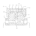
以下、本発明の実施の形態について、図1を参照して説明する。本体1に蓋体2をねじ結合して内部に変圧室3を形成する。本体1に入口4と出口5をほぼ同一軸上に形成する。本体1に変圧室3の中心に開口する噴出孔6を開け、この噴出孔6を介して入口4と変圧室3を連通する。噴出孔6の外周囲に環状溝8を設けて、噴出孔6と環状溝8の間に環状の内輪弁座9を形成し、環状溝8の外周囲に内輪弁座9と同心円状の環状の外輪弁座10を形成する。環状溝8の下端を排出孔7を介して出口5に連通する。内輪弁座9と外輪弁座10に離着座して開閉弁を行う円板状の弁ディスク11を変圧室3内に配置する。
Hereinafter, an embodiment of the present invention will be described with reference to FIG. A
弁ディスク11の下面に案内棒12を弁ディスク11と一体に取り付ける。従って、弁ディスク11が上下動すれば、案内棒12も同じく上下動するものである。案内棒12の表面に螺旋状の溝13を形成する。また、案内棒12の表面には噴出孔6の上下を連通する連通路14を設ける。噴出孔6の孔径と案内棒12の直径は、案内棒12が上下に摺動できるだけの寸法とする。 A guide rod 12 is attached to the lower surface of the valve disk 11 integrally with the valve disk 11. Therefore, if the valve disk 11 moves up and down, the guide rod 12 also moves up and down. A spiral groove 13 is formed on the surface of the guide rod 12. In addition, a communication passage 14 is provided on the surface of the guide rod 12 to communicate the upper and lower sides of the ejection hole 6. The diameter of the ejection hole 6 and the diameter of the guide rod 12 are set to dimensions that allow the guide rod 12 to slide up and down.
上記のディスク式スチームトラップの作動を説明する。変圧室3内に蒸気が滞留していない場合は、噴出孔6を介して弁ディスク11に作用する入口4側の流体圧力により、弁ディスク11は内輪弁座9と外輪弁座10から離座して、入口4からの低温復水を環状溝8と排出孔7を介して出口5へ排出する。
The operation of the disc type steam trap will be described. When steam does not stay in the
復水が排出されて変圧室3内に蒸気が流入してくると、変圧室3内の圧力が上昇すると共に、弁ディスク11下面を高速の蒸気が流下して静圧低下を来たすことによって、弁ディスク11は内輪弁座9と外輪弁座10に着座して閉弁する。変圧室3内の蒸気が放熱等により凝縮しその蒸気圧力が低下してくると、弁ディスク11が内輪弁座9と外輪弁座10から離座して開弁する。以上のような開閉弁のサイクルを繰り返す場合において、弁ディスク11が上下方向へ移動する時に、弁ディスク11と一体に取り付けた案内棒12が、噴出孔6でガイドされることによって、弁ディスク11が傾斜することがなく、水平状態を維持することで、弁ディスク11の内外輪弁座9,10への着座面が偏磨耗することがない。また、案内棒12の表面に螺旋状の溝13を形成したことにより、高速の蒸気及び復水の流れによって弁ディスク11が回転され、弁ディスク11の内外輪弁座9,10への着座面が偏磨耗することがない。
When the condensate is discharged and steam flows into the
本発明は、蒸気配管系に発生する復水を自動的に排出するディスク式スチームトラップに利用することができる。 The present invention can be used for a disk-type steam trap that automatically discharges condensate generated in a steam piping system.
1 本体
2 蓋体
3 変圧室
4 入口
5 出口
6 噴出孔
7 排出孔
8 環状溝
9 内輪弁座
10 外輪弁座
11 弁ディスク
12 案内棒
13 螺旋状の溝
14 連通路
DESCRIPTION OF
Claims (1)
Priority Applications (1)
| Application Number | Priority Date | Filing Date | Title |
|---|---|---|---|
| JP2011056979A JP2012193776A (en) | 2011-03-15 | 2011-03-15 | Disc-type steam trap |
Applications Claiming Priority (1)
| Application Number | Priority Date | Filing Date | Title |
|---|---|---|---|
| JP2011056979A JP2012193776A (en) | 2011-03-15 | 2011-03-15 | Disc-type steam trap |
Publications (1)
| Publication Number | Publication Date |
|---|---|
| JP2012193776A true JP2012193776A (en) | 2012-10-11 |
Family
ID=47085863
Family Applications (1)
| Application Number | Title | Priority Date | Filing Date |
|---|---|---|---|
| JP2011056979A Withdrawn JP2012193776A (en) | 2011-03-15 | 2011-03-15 | Disc-type steam trap |
Country Status (1)
| Country | Link |
|---|---|
| JP (1) | JP2012193776A (en) |
-
2011
- 2011-03-15 JP JP2011056979A patent/JP2012193776A/en not_active Withdrawn
Similar Documents
| Publication | Publication Date | Title |
|---|---|---|
| JP2014513846A (en) | Flow regulator | |
| WO2018193774A1 (en) | Annular valve and valve body for annular valve | |
| JP2012193776A (en) | Disc-type steam trap | |
| JP2012107653A (en) | Disk type steam trap | |
| JP5394134B2 (en) | Disc type steam trap | |
| JP5275277B2 (en) | Control valve | |
| JP5005587B2 (en) | steam trap | |
| JP5431035B2 (en) | Disc type steam trap | |
| JP2013024259A (en) | Disk type steam trap | |
| JP5431048B2 (en) | Disc type steam trap | |
| JP2013024260A (en) | Disk type steam trap | |
| JP4536270B2 (en) | Disc type steam trap | |
| JP2012107654A (en) | Disk type steam trap | |
| JP2012167802A (en) | Disc type steam trap | |
| KR101652951B1 (en) | Pressure balance type ball valve | |
| KR102104744B1 (en) | High differential pressure regulating valve having offset pressure inlet passage | |
| JP6342054B1 (en) | Annular valve | |
| JP4536271B2 (en) | Disc type steam trap | |
| JP2008202621A (en) | Free float drain trap | |
| JP4704621B2 (en) | Disc type steam trap | |
| JP4704594B2 (en) | Disc type steam trap | |
| JP2009275848A (en) | Disc type steam trap | |
| JP2012107650A (en) | Disk type steam trap | |
| JP4540860B2 (en) | Disc type steam trap | |
| JP4540859B2 (en) | Disc type steam trap |
Legal Events
| Date | Code | Title | Description |
|---|---|---|---|
| A300 | Withdrawal of application because of no request for examination |
Free format text: JAPANESE INTERMEDIATE CODE: A300 Effective date: 20140603 |