JP2012192764A - Cabling structure of parking brake cable - Google Patents
Cabling structure of parking brake cable Download PDFInfo
- Publication number
- JP2012192764A JP2012192764A JP2011056430A JP2011056430A JP2012192764A JP 2012192764 A JP2012192764 A JP 2012192764A JP 2011056430 A JP2011056430 A JP 2011056430A JP 2011056430 A JP2011056430 A JP 2011056430A JP 2012192764 A JP2012192764 A JP 2012192764A
- Authority
- JP
- Japan
- Prior art keywords
- parking brake
- brake cable
- cross member
- vehicle
- space
- Prior art date
- Legal status (The legal status is an assumption and is not a legal conclusion. Google has not performed a legal analysis and makes no representation as to the accuracy of the status listed.)
- Withdrawn
Links
Images


Abstract
Description
本発明は、車体のフロアパネルの下方に配索されるパーキングブレーキケーブルの配索構造に関するものである。 The present invention relates to a parking brake cable routing structure that is routed below a floor panel of a vehicle body.
駐車中の車両に所定の制動力を掛けるためのパーキングブレーキ装置は、車体の車幅方向略中央に配置されたパーキングレバー又は運転席側に配置されたパーキングペダルと左右の後輪のブレーキ装置とを可撓性を有するパーキングブレーキケーブルによって接続して構成されている。ここで、パーキングブレーキケーブルは、パーキングレバー又はパーキングペダルから車体のフロアパネルの下に取り出された後、車幅方向中央を車両後方に向かって配索され、その後、左右に分岐されて車両外側方に延び、再び車両後方に延びて左右の後輪の各ブレーキ装置に接続されている。 A parking brake device for applying a predetermined braking force to a parked vehicle includes a parking lever arranged at a substantially central position in the vehicle width direction of the vehicle body or a parking pedal arranged on the driver's seat side and a brake device for left and right rear wheels. Are connected by a flexible parking brake cable. Here, after the parking brake cable is taken out from the parking lever or the parking pedal under the floor panel of the vehicle body, it is routed in the center in the vehicle width direction toward the rear of the vehicle, and then branched to the left and right to extend outward from the vehicle. To the rear of the vehicle and connected to the left and right rear wheel brake devices.
エンジンを駆動源とする車両にあっては、排気管やプロペラシャフトが通過するフロアトンネル内にパーキングブレーキケーブルが配索されている(例えば、特許文献1参照)。 In a vehicle using an engine as a drive source, a parking brake cable is routed in a floor tunnel through which an exhaust pipe and a propeller shaft pass (see, for example, Patent Document 1).
ところで、電動モータを駆動源とする電気自動車には車体のフロアパネルの下側に比較的大きなバッテリパックが取り付けられるため、パーキングブレーキケーブルをバッテリパックの搭載位置から外した位置とするために車幅方向片側に寄せて配索する必要がある。 By the way, in an electric vehicle using an electric motor as a drive source, a relatively large battery pack is attached to the lower side of the floor panel of the vehicle body, so that the parking brake cable is positioned to be removed from the battery pack mounting position. It is necessary to route it in one direction.
電気自動車におけるパーキングブレーキケーブル等の配索構造に関して、特許文献2には、フロアパネルとバッテリパックの上面の少なくとも一方に車両前後方向に向けて凹部を形成して両者間に車両前後方向に延在する部品保護室を形成し、この部品保護室にパーキングブレーキケーブル等を車両前後方向に配索する構成が提案されている。
With regard to a wiring structure such as a parking brake cable in an electric vehicle,
ところで、電気自動車において、パーキングブレーキケーブルをバッテリパックを避けて左右何れかの方向に寄せて配索する場合、従来はパーキングブレーキケーブルの一部がバッテリパックの取付スペース内に張り出していたため、その張り出した部分が下方から取り付けられるバッテリパック等の部品によって挟まれて損傷する可能性があった。 By the way, in an electric vehicle, when the parking brake cable is routed in either the left or right direction avoiding the battery pack, a part of the parking brake cable has conventionally protruded into the battery pack mounting space. There is a possibility that the damaged portion may be pinched and damaged by parts such as a battery pack attached from below.
本発明は上記問題に鑑みてなされたもので、その目的とする処は、パーキングブレーキケーブルを保護してその損傷を防ぐことができるパーキングブレーキケーブルの配索構造を提供することにある。 The present invention has been made in view of the above problems, and an object of the present invention is to provide a parking brake cable routing structure capable of protecting the parking brake cable and preventing the damage thereof.
上記目的を達成するため、請求項1記載の発明は、車両前後方向に延びる左右一対のサイドフレームと該サイドフレーム間に横架されたクロスメンバを備える車体のフロアパネルの下方に配索されるパーキングブレーキケーブルの配索構造として、前記クロスメンバに、左右何れか一方の前記サイドフレームの車両中央側の側壁に対向する縦壁を設け、該縦壁と前記サイドフレームの側壁との間に車両前後方向か開放した空間を形成し、該空間に前記パーキングブレーキケーブルを車両前後方向に通して配索したことを特徴とする。
In order to achieve the above object, the invention according to
請求項2記載の発明は、請求項1記載の発明において、前記クロスメンバの左右両端に、左右一対の前記サイドフレームの下面に締付固定されるブラケットをそれぞれ形成し、該ブラケットの車両中央側の端部を上方に屈曲させて前記縦壁を形成したことを特徴とする。 According to a second aspect of the present invention, in the first aspect of the present invention, brackets that are fastened and fixed to the lower surfaces of the pair of left and right side frames are respectively formed at the left and right ends of the cross member, The vertical wall is formed by bending the end of the upper part upward.
請求項3記載の発明は、請求項2記載の発明において、前記クロスメンバの左右の縦壁の上端部に水平な本体部を形成し、該本体部に下方から取付固定された部品と前記空間に配索されたパーキングブレーキケーブルとの間に前記クロスメンバの一方の縦壁が配置されるよう構成したことを特徴とする。 According to a third aspect of the present invention, in the second aspect of the present invention, a horizontal main body portion is formed at the upper ends of the left and right vertical walls of the cross member, and the component and the space mounted and fixed to the main body portion from below. One vertical wall of the cross member is arranged between the parking brake cable and the parking brake cable.
請求項1記載の発明によれば、左右何れか一方のサイドフレームの側壁と該側壁に対向するクロスメンバの縦壁との間に形成された空間にパーキングブレーキケーブルを車両前後方向に通して配索したため、該パーキングブレーキケーブルがバッテリパック等の部品の取付スペース内に張り出すことがなく、部品の下方からの取付時にパーキングブレーキケーブルが部品によって挟み込まれて損傷するという不具合の発生が防がれるとともに、部品の取付作業性が高められる。又、パーキングブレーキケーブルの一部(空間内に配索される部分)がサイドフレームとクロスメンバによって保護されるため、その部分の他の部品との干渉や飛石等による損傷が防がれる。 According to the first aspect of the present invention, the parking brake cable is routed in the vehicle front-rear direction in a space formed between the side wall of one of the left and right side frames and the vertical wall of the cross member facing the side wall. As a result, the parking brake cable does not protrude into the mounting space for parts such as a battery pack, and it is possible to prevent the parking brake cable from being damaged by being pinched by the parts when the parts are attached from below. At the same time, the mounting workability of the parts is improved. In addition, since a part of the parking brake cable (part arranged in the space) is protected by the side frame and the cross member, interference with other parts of the part and damage due to flying stones or the like can be prevented.
請求項2記載の発明によれば、クロスメンバの左右両端に形成されたブラケットを締付固定することによって該クロスメンバを左右一対のサイドフレームに取り付けることができるとともに、各ブラケットの車両中央側の端部を上方に屈曲させて縦壁を形成することによって該縦壁とこれに対向する一方のサイドフレームの側壁との間に空間を容易に形成することができる。又、クロスメンバの左右の縦壁との間に形成される空間をパーキングブレーキケーブル等の部品を配置するスペースとして有効利用することができるとともに、部品の左右をクロスメンバの左右の縦壁によって保護することができる。更に、空間の下方はクロスメンバのブラケットによって塞がれるため、空間に配索されるパーキングブレーキケーブルを飛石等から保護することができるとともに、該パーキングブレーキケーブルの空間からの脱落が防がれる。 According to the second aspect of the present invention, the cross members can be attached to the pair of left and right side frames by tightening and fixing the brackets formed at the left and right ends of the cross member, By bending the end portion upward to form a vertical wall, a space can be easily formed between the vertical wall and the side wall of one side frame facing the vertical wall. In addition, the space formed between the left and right vertical walls of the cross member can be used effectively as a space for arranging parts such as parking brake cables, and the left and right parts of the cross member are protected by the left and right vertical walls of the cross member. can do. Furthermore, since the lower part of the space is blocked by the bracket of the cross member, the parking brake cable routed in the space can be protected from flying stones and the like, and the parking brake cable can be prevented from falling out of the space.
請求項3記載の発明によれば、クロスメンバの縦壁ではなく本体部に部品が下方から取付固定されるため、パーキングブレーキケーブルを配索する空間を容易に形成することができるとともに、クロスメンバに高い寸法精度を要することなく、部品を作業性良くクロスメンバの本体部に取り付けることができる。そして、クロスメンバの縦壁が部品取付時の部品とパーキングブレーキケーブルとの干渉を防いで該パーキングブレーキケーブルの損傷を防ぐことができる。 According to the third aspect of the present invention, since the parts are attached and fixed to the main body from below rather than the vertical wall of the cross member, a space for routing the parking brake cable can be easily formed, and the cross member Therefore, the parts can be attached to the main body of the cross member with good workability without requiring high dimensional accuracy. And the vertical wall of a cross member can prevent interference with the components and parking brake cable at the time of component mounting, and can prevent the parking brake cable from being damaged.
以下に本発明の実施の形態を添付図面に基づいて説明する。 Embodiments of the present invention will be described below with reference to the accompanying drawings.
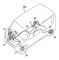
図1はパーキングブレーキケーブルの配索状態を示す車両の透視的斜視図であり、図示の車両100はワンボックスタイプの電気自動車であって、その車室内の運転席側である右側にはブレーキペダル20、該ブレーキペダル20に加えられる運転者の踏力を倍力するためのブレーキブースタ21、該ブレーキブースタ21によって倍力された運転者の踏力によって駆動されるマスタシリンダ22、運転者が足で踏み込むことによってパーキングブレーキ操作を行うためのパーキングブレーキペダル23が配されている。
FIG. 1 is a perspective view of a vehicle showing a state in which a parking brake cable is routed. A
上記マスタシリンダ22から延びるブレーキ配管24は、左右一対の前輪25と後輪26にそれぞれ設けられたブレーキ装置27,28の不図示のホイールシリンダに接続されており、運転者がブレーキペダル20を踏み込むことによってマスタシリンダ22に発生するブレーキ液圧はブレーキ配管24を経て前輪25と後輪26の各ブレーキ装置27,28のホイールシリンダに伝達され、このブレーキ液圧によって各ブレーキ装置27,28が作動して前輪25と後輪26の回転に所要の制動が加えられる。
The
又、前記パーキングブレーキペダル23には可撓性を有するパーキングブレーキケーブル1の一端が転結されており、このパーキングブレーキケーブル1は、パーキングブレーキペダル23からダッシュパネル又はフロアパネルの開口を通過して車体の不図示のフロアパネルの下に取り出された後、車両の右側側方に向かって斜めに配索され、その後、車幅方向右側に沿って車両後方へと延びた後、車幅方向中央側へと略直角に折り曲げられ、車両の中央位置にて再び車両後方に向かって略直角に折り曲げられて車幅方向中央を車両後方に向かって延び、その端部がイコライザ2に接続されている。そして、イコライザ2からは左右2本のパーキングブレーキケーブル3が左右に分岐して延びており、各パーキングブレーキケーブル3は後方に向かって折り曲げられて左右の各後輪26のブレーキ装置28にそれぞれ接続されている。
One end of a flexible
而して、停車時に運転者がパーキングブレーキペダル23を踏み込むと、その踏力がパーキングブレーキケーブル1とイコライザ2及び左右2本のパキングブレーキケーブ3を介して左右の後輪26の各ブレーキ装置28にそれぞれ伝達され、左右の各ブレーキ装置28が駆動されて駐車中の車両100の後輪26の回転がロックされて車両100の移動が防がれる。
Thus, when the driver depresses the parking brake pedal 23 when the vehicle stops, the pedaling force is applied to the
次に、前記パーキングブレーキケーブル1の配索構造を図2〜図7に基づいて説明する。
Next, the routing structure of the
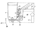
図2は本発明に係るパーキングブレーキケーブルの配索構造を備える車体フレームを斜め下方から見た部分斜視図、図3は図2のA部拡大詳細図、図4は図2のA部を前方斜め下方から見た斜視図、図5は図2のA部を正面から見た図、図6は車体フレームのクロスメンバの平面図、図7は図6のB−B線断面図である。 2 is a partial perspective view of a vehicle body frame having a parking brake cable routing structure according to the present invention as seen obliquely from below, FIG. 3 is an enlarged detail view of part A in FIG. 2, and FIG. 4 is a front view of part A in FIG. FIG. 5 is a front view of portion A of FIG. 2, FIG. 6 is a plan view of a cross member of the vehicle body frame, and FIG. 7 is a cross-sectional view taken along line BB of FIG.
図2に示すように、車体の前部には車両前後方向に延びる左右一対のサイドフレーム4が設けられており、これらのサイドフレーム4の前端には車幅方向に延びるフロントロアクロスメンバ5が横架されている。又、左右のサイドフレーム4間の前記フロントロアクロスメンバ5の後方にはクロスメンバ6,7が車両前後方向に適当な間隔を設けて横架されている。
As shown in FIG. 2, a pair of left and
ここで、上記クロスメンバ(ヒータクロスメンバ)7の構成の詳細を図6及び図7に基づいて説明する。 Here, the detailed configuration of the cross member (heater cross member) 7 will be described with reference to FIGS.
図6に示すように、クロスメンバ7は、矩形枠状を成す水平な本体部7Aの左右両端部にブラケット7Bを形成することによって構成されている。具体的には、図7に示すように、クロスメンバ7の本体部7Aの左右に形成されたブラケット7Bの車幅方向中央側の端部は上方に屈曲されて垂直な縦壁7aが形成されており、左右の縦壁7aの上端部に矩形枠状の水平な前記本体部7Aが溶接されている。そして、図6に示すように、右側のブブラケット7Bの前後には円孔8が形成され、左側のブラケット7Bの前後には長孔9が形成されている。
As shown in FIG. 6, the
而して、図2〜図5に示すように、クロスメンバ7は、その左右のブラケット7Bがこれに形成された前記円孔8と長孔9に下方から挿通するボルト10とこれに螺合するナット11(図5参照)によって左右の各サイドフレーム4の下面に締付固定されることによって、左右のサイドフレーム4間に横架されている。そして、図5に示すように、右側のサイドフレーム4の車幅方向中央側の側壁4aと該側壁4aに対向して側壁4aに沿って配置されるクロスメンバ7の右側の縦壁7aとの間には車両前後方向(図5の手前側と奥側)が開放された空間S1が形成されており、この空間S1にパーキングブレーキケーブル1が車両前後方向に通されて配索されている。尚、図3及び図4に示すように、空間S1に通されて配索されるパーキングブレーキケーブル1の空間S1外の一部はクランプ12によって右側のサイドフレーム4に固定されている。
Thus, as shown in FIGS. 2 to 5, the
ところで、電動モータを駆動源として走行する車両100には、電源として複数のバッテリを組み込んで成る比較的大きなバッテリパック13が搭載されるが、このバッテリパック13は、図5に示すようにクロスメンバ7の本体部7Aと左右の縦壁7aとの間に形成される空間S2に配置され、クロスメンバ7の本体部7Aの下面に下方から取付固定される。
Incidentally, a relatively
以上のように、本実施の形態では、右側のサイドフレーム4の側壁4aと該側壁4aに対向するクロスメンバ7の縦壁7aとの間に形成された空間S1にパーキングブレーキケーブル1を車両前後方向に通して配索したため、該パーキングブレーキケーブル1がバッテリパック13の取付スペース内に張り出すことがなく、バッテリパック13をクロスメンバ7の本体部7Aに下方から取り付ける際にパーキングブレーキケーブル1がバッテリパック13によって挟み込まれて損傷するという不具合の発生が防がれるとともに、バッテリパック13の取付作業のガイドとして機能して取付作業性が高められる。そして、この場合、パーキングブレーキケーブル1の一部(空間S1内に配索される部分)がサイドフレーム4の側壁4aとクロスメンバ7の縦壁7aによって保護されるため、その部分の他の部品との干渉や飛石等による損傷が防がれる。
As described above, in the present embodiment, the
又、本実施の形態では、クロスメンバ7の左右両端に形成されたブラケット7Bを締付固定することによって該クロスメンバ7を左右一対のサイドフレーム4に取り付けることができるとともに、各ブラケット7Bの車両中央側の端部を上方に屈曲させて縦壁7aを形成することによって該縦壁7aとこれに対向する右側のサイドフレーム4の側壁4aとの間に空間S1を容易に形成することができる。そして、クロスメンバ7の左右の縦壁7aの間に形成される空間S2をバッテリパック13を配置するスペースとして有効利用することができるとともに、バッテリパック13の左右をクロスメンバ7の左右の縦壁7aによって保護することができる。又、空間S1の下方はクロスメンバ7の右側のブラケット7Bによって塞がれるため、空間S1に配索されるパーキングブレーキケーブル1を飛石等から保護することができるとともに、該パーキングブレーキケーブル1の空間S1からの脱落が防がれる。
In the present embodiment, the
更に、本実施の形態では、クロスメンバ7の縦壁7aではなく本体部7Aにバッテリパック13が下方から取付固定されるため、パーキングブレーキケーブル1を配索する空間S1を容易に形成することができるとともに、クロスメンバ7に高い寸法精度を要することなく、バッテリパック13を作業性良くクロスメンバ7の本体部7Aに取り付けることができる。そして、クロスメンバ7の縦壁7aがバッテリパック13を取り付ける際に該バッテリパック13とパーキングブレーキケーブル1との干渉を防ぐため、パーキングブレーキケーブル1のバッテリパック13との干渉による損傷が防がれる。
Further, in the present embodiment, since the
尚、以上の実施の形態では、踏み込み式のパーキングブレーキペダルから延びるパーキングブレーキケーブルの配索構造に対して本発明を適用した形態について説明したが、本発明は、運転者が手で操作する手動式のパーキングブレーキレバーから延びるパーキングブレーキケーブルの配索構造に対しても同様に適用可能であることは勿論である。 In the above embodiment, the embodiment in which the present invention is applied to the wiring structure of the parking brake cable extending from the stepping type parking brake pedal has been described. However, the present invention is a manual operation that is manually operated by the driver. Needless to say, the present invention is also applicable to a parking brake cable routing structure extending from a parking brake lever of the type.
1,3 パーキングブレーキケーブル
4 サイドフレーム
4a サイドフレームの側壁
7 クロスメンバ
7A クロスメンバの本体部
7B クロスメンバのブラケット
7a クロスメンバの縦壁
10 ボルト
11 ナット
13 バッテリパック(部品)
23 パーキングブレーキペダル
27,28 ブレーキ装置
100 車両
S1,S2 空間
1, 3
23
Claims (3)
前記クロスメンバに、左右何れか一方の前記サイドフレームの車両中央側の側壁に対向する縦壁を設け、該縦壁と前記サイドフレームの側壁との間に車両前後方向か開放した空間を形成し、該空間に前記パーキングブレーキケーブルを車両前後方向に通して配索したことを特徴とするパーキングブレーキケーブルの配索構造。 A parking brake cable routing structure that is routed below a floor panel of a vehicle body that includes a pair of left and right side frames extending in the vehicle front-rear direction and a cross member horizontally mounted between the side frames,
The cross member is provided with a vertical wall that faces the side wall of the vehicle center side of either one of the left and right side frames, and an open space in the vehicle front-rear direction is formed between the vertical wall and the side frame side wall. A parking brake cable routing structure, wherein the parking brake cable is routed through the space in the vehicle longitudinal direction.
A horizontal main body is formed at the upper ends of the left and right vertical walls of the cross member, and the cross member is mounted between a part fixedly attached to the main body from below and a parking brake cable routed in the space. 3. The parking brake cable routing structure according to claim 2, wherein one of the vertical walls is arranged.
Priority Applications (1)
| Application Number | Priority Date | Filing Date | Title |
|---|---|---|---|
| JP2011056430A JP2012192764A (en) | 2011-03-15 | 2011-03-15 | Cabling structure of parking brake cable |
Applications Claiming Priority (1)
| Application Number | Priority Date | Filing Date | Title |
|---|---|---|---|
| JP2011056430A JP2012192764A (en) | 2011-03-15 | 2011-03-15 | Cabling structure of parking brake cable |
Publications (1)
| Publication Number | Publication Date |
|---|---|
| JP2012192764A true JP2012192764A (en) | 2012-10-11 |
Family
ID=47085110
Family Applications (1)
| Application Number | Title | Priority Date | Filing Date |
|---|---|---|---|
| JP2011056430A Withdrawn JP2012192764A (en) | 2011-03-15 | 2011-03-15 | Cabling structure of parking brake cable |
Country Status (1)
| Country | Link |
|---|---|
| JP (1) | JP2012192764A (en) |
Cited By (4)
| Publication number | Priority date | Publication date | Assignee | Title |
|---|---|---|---|---|
| WO2014034422A1 (en) * | 2012-08-30 | 2014-03-06 | 日産自動車株式会社 | Parking brake device for electric vehicle and assembly method thereof |
| WO2014034421A1 (en) * | 2012-08-30 | 2014-03-06 | 日産自動車株式会社 | Parking brake device for electric vehicle |
| CN112141023A (en) * | 2019-06-28 | 2020-12-29 | 丰田自动车株式会社 | Vehicle lower structure |
| JP2021066205A (en) * | 2019-10-17 | 2021-04-30 | 本田技研工業株式会社 | vehicle |
-
2011
- 2011-03-15 JP JP2011056430A patent/JP2012192764A/en not_active Withdrawn
Cited By (8)
| Publication number | Priority date | Publication date | Assignee | Title |
|---|---|---|---|---|
| WO2014034422A1 (en) * | 2012-08-30 | 2014-03-06 | 日産自動車株式会社 | Parking brake device for electric vehicle and assembly method thereof |
| WO2014034421A1 (en) * | 2012-08-30 | 2014-03-06 | 日産自動車株式会社 | Parking brake device for electric vehicle |
| JP5831640B2 (en) * | 2012-08-30 | 2015-12-09 | 日産自動車株式会社 | Parking brake device for electric vehicle |
| JP5880716B2 (en) * | 2012-08-30 | 2016-03-09 | 日産自動車株式会社 | Parking brake device for electric vehicle and method for assembling the same |
| CN112141023A (en) * | 2019-06-28 | 2020-12-29 | 丰田自动车株式会社 | Vehicle lower structure |
| US11312419B2 (en) | 2019-06-28 | 2022-04-26 | Toyota Jidosha Kabushiki Kaisha | Vehicle lower portion structure |
| JP2021066205A (en) * | 2019-10-17 | 2021-04-30 | 本田技研工業株式会社 | vehicle |
| JP7023911B2 (en) | 2019-10-17 | 2022-02-22 | 本田技研工業株式会社 | vehicle |
Similar Documents
| Publication | Publication Date | Title |
|---|---|---|
| JP5652604B2 (en) | Electric vehicle body structure | |
| KR20150110648A (en) | Electric vehicle | |
| WO2011145409A1 (en) | Mounting structure for electric device at rear of vehicle body | |
| JP5494333B2 (en) | Car cable routing structure | |
| WO2011155238A1 (en) | Automotive dash panel structure | |
| JP2006224877A (en) | Car body floor structure | |
| JP2012192764A (en) | Cabling structure of parking brake cable | |
| JP2001294141A (en) | Arranging structure for abs system | |
| JP6060864B2 (en) | Storage device arrangement structure | |
| JP5667964B2 (en) | Vehicle cable arrangement structure and vehicle assembly method | |
| JP2014227153A (en) | Attachment structure of accessory device for vehicle | |
| JP5928289B2 (en) | High voltage harness protection structure for vehicles | |
| JP5971132B2 (en) | Support device for electrical component for vehicle | |
| JP6753156B2 (en) | Battery pack protection structure | |
| JP7200855B2 (en) | vehicle undercarriage | |
| JPH10250549A (en) | Actuator installing structure of antilock brake system | |
| JP7238628B2 (en) | Installation structure of electrical equipment for vehicles | |
| JP3810780B2 (en) | Arrangement structure of high voltage line | |
| JP6945936B2 (en) | Protective structure of wiring parts | |
| JP2022150715A (en) | Electric vehicle understructure | |
| JP6686735B2 (en) | Battery mounting structure | |
| JP2009035215A (en) | Battery mounting structure for motor vehicle | |
| JP7411165B2 (en) | Actuator sound insulation structure | |
| JPH0867150A (en) | Part mounting structure in motor room for electric automobile | |
| JP7367594B2 (en) | Battery car body grounding structure and battery car body grounding method |
Legal Events
| Date | Code | Title | Description |
|---|---|---|---|
| RD04 | Notification of resignation of power of attorney |
Free format text: JAPANESE INTERMEDIATE CODE: A7424 Effective date: 20121206 |
|
| RD02 | Notification of acceptance of power of attorney |
Free format text: JAPANESE INTERMEDIATE CODE: A7422 Effective date: 20121207 |
|
| A300 | Withdrawal of application because of no request for examination |
Free format text: JAPANESE INTERMEDIATE CODE: A300 Effective date: 20140603 |