JP2012192571A - Liquid discharge head and recording apparatus - Google Patents
Liquid discharge head and recording apparatus Download PDFInfo
- Publication number
- JP2012192571A JP2012192571A JP2011057118A JP2011057118A JP2012192571A JP 2012192571 A JP2012192571 A JP 2012192571A JP 2011057118 A JP2011057118 A JP 2011057118A JP 2011057118 A JP2011057118 A JP 2011057118A JP 2012192571 A JP2012192571 A JP 2012192571A
- Authority
- JP
- Japan
- Prior art keywords
- layer
- liquid
- diaphragm
- discharge head
- head according
- Prior art date
- Legal status (The legal status is an assumption and is not a legal conclusion. Google has not performed a legal analysis and makes no representation as to the accuracy of the status listed.)
- Granted
Links
Images


Landscapes
- Particle Formation And Scattering Control In Inkjet Printers (AREA)
Abstract
【課題】加圧液室はもとより補強部においても構造コンプライアンスのばらつきを低減することが可能な液体吐出ヘッド及びこれを用いる記録装置を提供する。
【解決手段】振動板61と、振動板61の一方の面上に形成された変位発生手段70と、振動板61の他方の面に接続し流路隔壁66aにより区画されてなる加圧液室66bと、加圧液室66bに連通するノズル孔67aとを有し、加圧液室66bに収容された液体が変位発生手段70により生じた振動板61の変位により加圧され、加圧された液体をノズル孔67aより液滴として吐出する液体吐出ヘッド7において、振動板61の一方の面上かつ流路隔壁66aと対向する位置であって流路隔壁66aよりも加圧液室66b側に突出する補強部材68を設け、補強部材68を少なくとも2層以上の複数層を有する積層体から構成し、積層体を構成する全ての層の中で最大の曲げ剛性を有する層68bを振動板61に接する層以外の層とした。
【選択図】図3The present invention provides a liquid discharge head capable of reducing variations in structural compliance not only in a pressurized liquid chamber but also in a reinforcing portion, and a recording apparatus using the liquid discharge head.
SOLUTION: A diaphragm 61, a displacement generating means 70 formed on one surface of the diaphragm 61, and a pressurized liquid chamber connected to the other surface of the diaphragm 61 and partitioned by a flow path partition 66a. 66b and a nozzle hole 67a communicating with the pressurized liquid chamber 66b. The liquid stored in the pressurized liquid chamber 66b is pressurized and pressurized by the displacement of the diaphragm 61 generated by the displacement generating means 70. In the liquid ejection head 7 that ejects the liquid as droplets from the nozzle holes 67a, the pressure liquid chamber 66b side is located on one surface of the diaphragm 61 and at a position facing the flow path partition wall 66a. The reinforcing member 68 is provided on the substrate, and the reinforcing member 68 is constituted by a laminate having at least two or more layers, and the layer 68b having the maximum bending rigidity among all the layers constituting the laminate is provided as the diaphragm. Other than the layer in contact with 61 .
[Selection] Figure 3
Description
本発明は、ノズル孔等の穴部からインク液滴等の液体を吐出する液体吐出ヘッドの構造、及びこれを用いた記録装置に関する。 The present invention relates to a structure of a liquid discharge head for discharging a liquid such as an ink droplet from a hole such as a nozzle hole, and a recording apparatus using the structure.
画像形成装置として、ノズル孔からインク液滴を吐出して記録媒体上に着弾させることにより画像形成を行うインクジェットプリンタが広く普及しており、中でも記録に供するインク液滴のみを選択的に吐出する、いわゆるオンデマンド方式のものが主流となっている。このオンデマンド方式は、インク液が吐出する運動エネルギの発生原理により、電気・機械変換素子である圧電素子の動作により生じる加圧液室体積変位によってインク液中に圧力を発生させてこの圧力からインク液滴吐出の運動エネルギを得るいわゆるピエゾ方式、電気・機械変換素子として静電アクチュエータを用いる静電方式、電気・熱変換素子によりインク液中に気泡を発生させてこの気泡の膨張によりインクを排除することによりインク液滴吐出の運動エネルギを得るいわゆるサーマル方式等に分類される。 As an image forming apparatus, an ink jet printer that forms an image by ejecting ink droplets from nozzle holes and landing on a recording medium is widely used. Among them, only ink droplets for recording are selectively ejected. The so-called on-demand system has become the mainstream. In this on-demand method, pressure is generated in the ink liquid by the volume displacement of the pressurized liquid chamber caused by the operation of the piezoelectric element, which is an electromechanical conversion element, based on the generation principle of the kinetic energy discharged from the ink liquid. So-called piezo method for obtaining the kinetic energy of ink droplet ejection, electrostatic method using an electrostatic actuator as an electrical / mechanical conversion element, and generation of bubbles in the ink liquid by the electrical / thermal conversion element. It is classified into a so-called thermal method or the like that obtains kinetic energy of ink droplet discharge by eliminating.
さらに、ピエゾ方式における駆動方式として、加圧液室に接して設けられた振動板を別の構造体に支持されたバルク状のピエゾ素子が押す(または引く)ことにより加圧液室体積変位を得るいわゆるブッシュモード、加圧液室に接して設けられた振動板上に形成された板状のピエゾ素子が内面方向に伸縮することにより振動板に撓み変形を生じさせて加圧液室体積変位を得るいわゆるベンドモード、加圧液室を構成する部材の一部が圧電素子であってこの圧電素子が剪断変形することにより加圧液室体積変位を得るいわゆるシェアモード等が挙げられる。何れの方式においても加圧液室及びノズル孔は列状あるいは格子状となるように複数配列されることが一般的であり、近年は記録装置に対する高画質化及び低コスト化への要求に応えるため、高解像度及び実装面積収縮を両立すべく実装の高集積化が進展している。 Furthermore, as a driving method in the piezo method, the volume displacement of the pressurized liquid chamber is changed by pressing (or pulling) a bulk piezoelectric element supported by another structure on a diaphragm provided in contact with the pressurized liquid chamber. The so-called bush mode is obtained. The plate-shaped piezo element formed on the diaphragm provided in contact with the pressurized liquid chamber expands and contracts in the direction of the inner surface, causing the diaphragm to bend and deform, thereby changing the volume of the pressurized liquid chamber. A so-called bend mode for obtaining the pressure liquid chamber, and a so-called shear mode for obtaining a volume displacement of the pressure liquid chamber by a part of the member constituting the pressure liquid chamber being a piezoelectric element and shearing deformation of the piezoelectric element. In any method, it is common that a plurality of pressurized liquid chambers and nozzle holes are arranged in a row or a lattice, and recently, in response to the demand for higher image quality and lower cost for recording apparatuses. Therefore, high integration of mounting is progressing so as to achieve both high resolution and shrinking mounting area.
上述の動向に対応し、半導体プロセスやマイクロマシニング技術を利用した液滴吐出ヘッドの製造方法が提案されている。これは、シリコン基板の片面上に成膜法及びリソグラフィ法等により薄膜状のピエゾ素子のパターンを直接形成すると共に、このシリコン基板の反対側の面にリソグラフィ法により加圧液室を直接形成するものであり、この製造方法によるヘッドは振動板と薄膜状のピエゾ素子とが薄膜アクチュエータを構成し、駆動方式としてはベンドモードに該当する。この方法によれば、機械加工では困難な微細形状の実現が可能であると共に、振動板・ピエゾ素子貼付のような構造部材の位置合わせ工程を大幅に削減できるため、液滴吐出ヘッドの高集積化、低コスト化等の面で有利となる。 In response to the above-described trends, a method for manufacturing a droplet discharge head using a semiconductor process or micromachining technology has been proposed. In this method, a thin-film piezo element pattern is directly formed on one surface of a silicon substrate by a film forming method, a lithography method, or the like, and a pressurized liquid chamber is directly formed on the opposite surface of the silicon substrate by a lithography method. In the head according to this manufacturing method, the diaphragm and the thin film piezo element constitute a thin film actuator, and the drive system corresponds to the bend mode. According to this method, it is possible to realize a fine shape that is difficult to machine, and to greatly reduce the alignment process of structural members such as attaching diaphragms and piezo elements. This is advantageous in terms of cost reduction and cost reduction.
上述の液滴吐出ヘッドでは、一般に加圧液室の構造コンプライアンス(単位圧力当たりの体積変位量)が吐出特性に大きく影響する。薄膜アクチュエータを用いた液滴吐出ヘッドの場合には、構造コンプライアンスが最大となる部位は薄膜アクチュエータであり、特にアクチュエータの可動部面積のばらつきは吐出特性のばらつきに直結する。一方、高集積化されたヘッドの加工においては、加工深さを加工幅で除した値で定義されるアスペクト比が高くなりがちであり、これは列状にノズル孔を配列する場合に、平面形状として幅が狭く細長い形状を採る構成において顕著である。アスペクト比の高い加圧液室をリソグラフィ法で加工する場合にエッチング時における形状ばらつきの発生は不可避であるため、従来技術にみられる加圧液室端部がアクチュエータの可動部面積を規定する構成では構造コンプライアンスのばらつきを押さえることが困難であり、このことが不安定な吐出特性に繋がっていた。 In the above-described droplet discharge head, generally, the structural compliance (volume displacement per unit pressure) of the pressurized liquid chamber greatly affects the discharge characteristics. In the case of a droplet discharge head using a thin film actuator, the portion where the structural compliance is maximum is a thin film actuator, and in particular, variations in the area of the movable part of the actuator are directly related to variations in discharge characteristics. On the other hand, in the processing of highly integrated heads, the aspect ratio defined by the value obtained by dividing the processing depth by the processing width tends to be high. This is a problem when the nozzle holes are arranged in a row. This is remarkable in the configuration in which the shape is narrow and narrow. When processing a pressurized liquid chamber with a high aspect ratio by lithography, shape variations during etching are inevitable, so the end of the pressurized liquid chamber found in the prior art defines the area of the movable part of the actuator However, it is difficult to suppress variations in structural compliance, which leads to unstable ejection characteristics.
上述の問題点を解決する方法として、加圧液室端部以外の部位により、あるいは別部材を配置することにより振動板の可動部面積を規定する構成が各種提案されている。例えば「特許文献1」には、静電方式の液滴吐出ヘッドに関し、加圧液室幅よりも間隔の狭い壁面に対向する側に振動板を配置してその可動部面積を高精度に規定する技術が、「特許文献2」には、ピエゾ方式の液滴吐出ヘッドに関し、加圧液室側に補強部である振動規制層を設ける技術がそれぞれ開示されている。これ等の技術では、加圧液室端部にて振動板の可動部面積を規定するものに比してより高精度に振動板の可動部面積を規定できるため、構造コンプライアンスのばらつきを低減させることができる。また、加圧液室と対向する側に補強部を設けることにより、補強部としてインク液との接液性による材質の制約を受けないため、補強部を構成する材質の選択自由度が高いというメリットもある。
As a method for solving the above-described problems, various configurations have been proposed in which the movable portion area of the diaphragm is defined by a portion other than the end portion of the pressurized liquid chamber or by disposing another member. For example, “Patent Document 1” relates to an electrostatic droplet discharge head, and a diaphragm is arranged on the side facing a wall surface having a narrower interval than the pressurized liquid chamber width, and the area of the movable part is defined with high accuracy.
しかし、さらなる構造コンプライアンスのばらつきを考え高集積な液滴吐出ヘッドを製作する場合には補強部の形成工程にもリソグラフィ法が選択されることとなるが、そのアスペクト比の低さから加圧液室形成時ほど顕著ではないものの加工ばらつきの発生は不可避である。これは、エッチング深さをエッチングストップ層によって規制したときに幅方向にエッチングが進行するためである。このばらつきは一般的に振動板近傍ほど大きなものとなるため、ばらつきの低減は振動板の可動部面積を規定する上で非常に重要となる。また、補強部によって振動板の可動部面積を規定していることから振動板の変形時において補強部にも応力が作用するが、補強部に作用する応力はその中立軸を中心として振動板側の面とこれとは逆側の面とでは逆方向となる。 However, when manufacturing highly integrated liquid droplet ejection heads considering the further variation in structural compliance, the lithography method is also selected for the reinforcement forming process. Although not as noticeable as when the chamber is formed, processing variations are unavoidable. This is because etching proceeds in the width direction when the etching depth is regulated by the etching stop layer. Since this variation generally becomes larger as the vicinity of the diaphragm, the reduction of the variation is very important in defining the movable part area of the diaphragm. In addition, since the area of the movable part of the diaphragm is defined by the reinforcing part, stress also acts on the reinforcing part when the diaphragm is deformed, but the stress acting on the reinforcing part is centered on its neutral axis. The surface is opposite to the surface on the opposite side.
本発明は上述の点に鑑み、加圧液室はもとより補強部においても構造コンプライアンスのばらつきを低減することが可能な液体吐出ヘッド及びこれを用いる記録装置の提供を目的とする。 SUMMARY OF THE INVENTION The present invention has been made in view of the above points, and it is an object of the present invention to provide a liquid discharge head capable of reducing variations in structural compliance not only in a pressurized liquid chamber but also in a reinforcing portion, and a recording apparatus using the same.
請求項1記載の発明は、少なくとも一部が板状の可撓性部材からなる振動板と、前記振動板の一方の面上に形成された電気・機械変換素子の変形により前記振動板を変位させる変位発生手段と、前記振動板の他方の面に接続し流路隔壁により区画されてなる加圧液室と、前記加圧液室に連通するノズル孔とを有し、前記加圧液室に収容された液体が前記変位発生手段により生じた前記振動板の変位により加圧され、加圧された前記液体を前記ノズル孔より液滴として吐出する液体吐出ヘッドにおいて、前記振動板の一方の面上であって前記流路隔壁と対向する位置に配設され前記流路隔壁よりも前記加圧液室側に突出した補強部材を有し、該補強部材は少なくとも2層以上の複数層を有する積層体からなると共に、前記積層体を構成する全ての層の中で最大の曲げ剛性を有する層が前記振動板に接する層以外の層であることを特徴とする。 According to a first aspect of the present invention, the diaphragm is displaced by deformation of a diaphragm made of at least a part of a plate-like flexible member and an electromechanical conversion element formed on one surface of the diaphragm. Displacement generating means, a pressurized liquid chamber connected to the other surface of the diaphragm and defined by a flow path partition, and a nozzle hole communicating with the pressurized liquid chamber, the pressurized liquid chamber In the liquid discharge head in which the liquid contained in the liquid is pressurized by the displacement of the vibration plate generated by the displacement generating means, and the pressurized liquid is discharged as a droplet from the nozzle hole, one of the vibration plates A reinforcing member which is disposed on the surface and is opposed to the flow path partition wall and protrudes to the pressurized liquid chamber side than the flow path partition wall, and the reinforcing member includes at least two or more layers. And comprising all of the laminates Characterized in that the layer having a maximum bending stiffness within the layers is a layer other than the layer in contact with the diaphragm.
請求項2記載の発明は、請求項1記載の液体吐出ヘッドにおいて、さらに前記最大の曲げ剛性を有する層は前記積層体を構成する全ての層の中で最大のヤング率を有する層であることを特徴とする。 According to a second aspect of the present invention, in the liquid discharge head according to the first aspect, the layer having the maximum bending rigidity is a layer having the maximum Young's modulus among all the layers constituting the laminate. It is characterized by.
請求項3記載の発明は、請求項1記載の液体吐出ヘッドにおいて、さらに前記最大の曲げ剛性を有する層は前記積層体を構成する全ての層の中で最大の厚みを有する層であることを特徴とする。 According to a third aspect of the present invention, in the liquid discharge head according to the first aspect, the layer having the maximum bending rigidity is a layer having the maximum thickness among all the layers constituting the laminate. Features.
請求項4記載の発明は、請求項1ないし3の何れか1つに記載の液体吐出ヘッドにおいて、さらに前記積層体を構成する全ての層の中で最小の曲げ剛性を有する層が前記振動板に接する層であることを特徴とする。 According to a fourth aspect of the present invention, in the liquid discharge head according to any one of the first to third aspects, a layer having a minimum bending rigidity among all the layers constituting the laminated body is the diaphragm. It is a layer which touches.
請求項5記載の発明は、請求項4記載の液体吐出ヘッドにおいて、さらに前記最小の曲げ剛性を有する層は前記積層体を構成する全ての層の中で最小のヤング率を有する層であることを特徴とする。 According to a fifth aspect of the present invention, in the liquid ejection head according to the fourth aspect, the layer having the minimum bending rigidity is a layer having the smallest Young's modulus among all the layers constituting the laminate. It is characterized by.
請求項6記載の発明は、請求項4記載の液体吐出ヘッドにおいて、さらに前記最小の曲げ剛性を有する層は前記積層体を構成する全ての層の中で最小の厚みを有する層であることを特徴とする。 According to a sixth aspect of the present invention, in the liquid discharge head according to the fourth aspect, the layer having the minimum bending rigidity is a layer having the minimum thickness among all the layers constituting the laminate. Features.
請求項7記載の発明は、請求項1ないし6の何れか1つに記載の液体吐出ヘッドにおいて、さらに前記振動板に接する層が二酸化ケイ素からなることを特徴とする。 According to a seventh aspect of the present invention, in the liquid discharge head according to any one of the first to sixth aspects, the layer in contact with the diaphragm is made of silicon dioxide.
請求項8記載の発明は、請求項1ないし7の何れか1つに記載の液体吐出ヘッドにおいて、さらに前記振動板に接する層以外の層が窒化ケイ素からなることを特徴とする。 According to an eighth aspect of the present invention, in the liquid discharge head according to any one of the first to seventh aspects, a layer other than the layer in contact with the diaphragm is made of silicon nitride.
請求項9記載の発明は、請求項1ないし8の何れか1つに記載の液体吐出ヘッドにおいて、さらに前記補強部材に接続された支持部材を有し、前記支持部材の前記補強部材に接続される部位の幅が前記補強部材の幅よりも小さいことを特徴とする。
The invention according to
請求項10記載の発明は、請求項1ないし9の何れか1つに記載の液体吐出ヘッドを有し、前記液体吐出ヘッドから液滴を吐出させて画像形成を行う記録装置であることを特徴とする。 A tenth aspect of the present invention is a recording apparatus that includes the liquid discharge head according to any one of the first to ninth aspects, and that forms an image by discharging liquid droplets from the liquid discharge head. And
本発明によれば、振動板の面上であって流路隔壁と対向する位置に流路隔壁よりも加圧液室側に突出した補強部材を設け、補強部材を少なくとも補強下層と補強上層との2層を有する積層体で構成し、積層体を構成する各層の中で最大の曲げ剛性を有する補強上層を振動板に接する層以外の層とすることにより大きな曲げ剛性向上効果を得ることができ、流路隔壁によって振動板の幅を規定する場合に比して構造コンプライアンスのばらつきを低減することができる。 According to the present invention, the reinforcing member that protrudes to the pressurized liquid chamber side from the flow path partition wall is provided on the surface of the diaphragm and facing the flow path partition wall, and the reinforcement member includes at least the reinforcing lower layer and the reinforcing upper layer. It is possible to obtain a large bending rigidity improvement effect by making the reinforcing upper layer having the maximum bending rigidity among the layers constituting the laminated body a layer other than the layer in contact with the diaphragm. In addition, it is possible to reduce the variation in the structural compliance as compared with the case where the width of the diaphragm is defined by the flow path partition wall.
図1は、本発明の一実施形態を採用した記録装置としてのインクジェットプリンタ1の正面図を、図2は同左側面図を示している。インクジェットプリンタ1は、左右の側板9に横架されたガイドロッド2により図1における紙面方向である主走査方向に摺動自在に保持されたキャリッジ3を有しており、主走査モータ4によって駆動プーリ6Aと従動プーリ6Bとに掛け渡されたタイミングベルト5を走行移動させることにより、タイミングベルト5に接続されたキャリッジ3を図2において左右方向である主走査方向に移動走査する。ガイドロッド2とキャリッジ3との間には2個のガイドブッシュ3aが配設されている。
FIG. 1 is a front view of an ink jet printer 1 as a recording apparatus adopting an embodiment of the present invention, and FIG. 2 is a left side view thereof. The ink jet printer 1 has a
キャリッジ3には、例えばそれぞれイエロ(Y)、シアン(C)、マゼンタ(M)、ブラック(Bk)のインク液を吐出する2個の液体吐出ヘッドであるヘッド7が設けられており、各ヘッド7はそれぞれ複数のインク吐出口であるノズル列を主走査方向とは直交する方向に備え、インク滴の吐出方向が水平となるようにキャリッジ3に取り付けられている。ヘッド7については後述する。
The
キャリッジ3には、ヘッド7に各色のインクを供給するための各色に対応したヘッドタンクが搭載されている。このヘッドタンクには、インク供給チューブを介して図示しないインクカートリッジからインクが補充供給される。なお、インク滴を吐出するヘッド7以外に、インクと反応することによりインクの定着性を高める定着用インクを吐出するヘッドを備えることも可能である。ヘッド7のノズルは乾燥によるノズル詰まりが発生し易く、印字中のエラー等による装置停止中や電源オフ時等のキャリッジ非稼働時には、ノズル面に対してキャップを被覆して保湿を行っている。吸引キャップ71及び保湿キャップ72はクリーニング装置に設けられており、クリーニング装置は装置本体の左右どちらかに配置されている。
A head tank corresponding to each color for supplying ink of each color to the
装置本体の下部には、給紙カセット10の用紙積載部11上に積載された用紙12を給紙する給紙部が配置されている。給紙部は、用紙積載部11から用紙12を給送する給紙ローラ13、給紙ローラ13に圧接配置され高摩擦抵抗部材からなる分離パッド14等を有しており、これ等により用紙積載部11上の用紙12が1枚ずつ分離給送される。
A paper feeding unit that feeds the
図1において給紙部の左方には、給紙部からの用紙12をヘッド7のノズル面に対して平行となるように搬送する搬送部が配設されている。搬送部は、用紙12を静電力により吸着して搬送する搬送ベルト21、給紙部より送られた用紙12を案内するガイド板15、用紙12の先端を検知する反射型センサからなる第1用紙有無検知センサ200、押さえ部材24により付勢され用紙12を搬送ベルト21に圧接させる先端加圧コロ25、押さえ部材24に固定され用紙12の先端を検知する反射型センサからなる第2用紙有無検知センサ201、搬送ベルト21の表面を帯電させる帯電ローラ26等を有している。無端ベルトからなる搬送ベルト21は搬送ローラ27とテンションローラ28との間に掛け渡されており、タイミングベルト32及びタイミングローラ33を介して副走査モータ31からの駆動力を受けた搬送ローラ27が回転駆動されることにより図2に示すベルト搬送方向(副走査方向)に走行駆動される。搬送ベルト21の裏面側であってヘッド7の画像形成領域と対応した部位にはガイド部材29が配設されている。
In FIG. 1, a conveyance unit that conveys the
図2に示すように搬送ローラ27の回転中心軸には光を透過する透過部と透過しない非透過部とが交互に形成された円板型のエンコーダシート34が取り付けられており、搬送ローラ27の回転中心軸を支持する側板にはエンコーダシート34の透過部と非透過部とを検知するエンコーダセンサ35が配設され、これ等によってエンコーダ36が構成されている。帯電ローラ26は搬送ベルト21の表層に接触しており、搬送ベルト21の移動に従動して回転する。
As shown in FIG. 2, a disk-shaped
キャリッジ3の前方側には、図1に示すように光を透過する透過部と透過しない非透過部とが交互に形成されたエンコーダシート42が設けられており、キャリッジ3の前面側にはエンコーダシート42の透過部と非透過部とを検出する透過型フォトセンサからなるエンコーダセンサが設けられ、これ等によってキャリッジ3の主走査方向における位置が検知される。さらに、ヘッド7によって記録された用紙12を排紙するための排紙部として、搬送ベルト21から用紙12を分離する分離爪51、排紙ローラ52及び排紙コロ53、排紙される用紙12をストックする排紙トレイ54等が設けられている。
As shown in FIG. 1, an
上述のインクジェットプリンタ1では給紙部から用紙12が1枚ずつ分離給送され、水平方向に給紙された用紙12はガイド板15によって垂直方向に案内されてその先端を第1用紙有無検知センサ200によって検知される。その後、用紙12は搬送ベルト21上に搬送され、先端加圧コロ25によって搬送ベルト21に押し付けられた状態で再度その先端を第2用紙有無検知センサ201によって検知される。このとき帯電ローラ26に対してプラス(正極)出力とマイナス(負極)出力とが交互に繰り返される交番電圧が印加され、搬送ベルト21にはその走行方向である副走査方向に、プラス及びマイナスの電荷が所定の幅で帯状に交互に印加される。このプラス及びマイナスに交互に帯電した搬送ベルト21上に用紙12が給送されると、用紙12が搬送ベルト21に静電力で吸着されて搬送ベルト21の周回移動により用紙12が副走査方向に搬送される。
In the ink jet printer 1 described above, the
上述の状態でキャリッジ3を移動させつつ画像信号に応じてヘッド7を駆動することにより、停止している用紙12にインク滴を吐出して1行分の記録を行い、用紙12を所定量搬送した後に次の行の記録を行う。記録終了信号または用紙12の後端が記録領域に到達した信号を受けることにより記録動作が終了し、用紙12は排紙ローラ52及び排紙コロ53によって排紙トレイ54上に排出される。このインクジェットプリンタ1では、1方向の走査時にのみ画像を形成する片方向記録モードと両方向の走査時の何れにも画像を形成する両方向記録モードとがあり、これをユーザからの指定や印刷画像に応じて設定するか、あるいは何れかのモードのみを行うかを任意に設定可能である。
By driving the
ヘッド7のノズルの回復やマシン停止中にノズルの保湿を行うクリーニング装置は、本実施形態においては図2に示すように装置本体の右側に配設されており、クリーニング装置のフレーム110は装置本体の右側板に位置決めされてねじにより固定されている。フレーム110内には図示しないキャッピング機構用ステッピングモータが配設されており、これを正回転させると図示しないギヤ及びカムを介して吸引キャップ71及び保湿キャップ72がキャッピングとデキャップ動作を実施する。また、図示しないキャッピング機構用ステッピングモータを逆回転させると、チュービングポンプによるポンプ駆動を実施する。
In this embodiment, the cleaning device for recovering the nozzles of the
フレーム110内には、ヘッド7のノズル面をクリーニングするワイピング機構が設けられている。このワイピング機構は、撥水性を有しノズル面に当接しつつ移動するワイパブレード101、ワイパブレード101を保持するホルダ部102及びスライダ103、それぞれ図示しないギヤ、ステッピングモータ、スライダ103の移動をガイドするガイドレール106等を有している。スライダ103にはラック部が形成されており、これにステッピングモータの出力軸に接続されたギヤが噛合している。ホルダ部102とスライダ103とは、一体であっても別体であってもよく、スライダ103が下方へと移動することにより、ノズル面に付着したインクや紙粉等の異物をワイパブレード101が除去する。
A wiping mechanism for cleaning the nozzle surface of the
ここで、本発明の特徴部であるヘッド7の構成について説明する。
図3は、本発明の一実施形態に用いられるヘッド7を示している。ヘッド7は、振動板61、共通電極62、圧電素子63、個別電極64、パッシベーション膜65、流路板66、ノズル板67、補強部材68、支持部材としての支持フレーム69等を有している。
Here, the configuration of the
FIG. 3 shows the
振動板61は、2〜4μm程度の厚みを有するシリコンオンインシュレーティングサブストレート(SOI:絶縁体層の上にケイ素層を形成するもの)、あるいはケイ素(Si)、二酸化ケイ素(SiO2)、窒化ケイ素(SiN)等による積層板からなり、振動板61の一方の面上に共通電極62、圧電素子63、個別電極64が積層され、これら全体をパッシベーション膜65にて被覆したものにより変位発生手段としての薄膜アクチュエータ70が構成されている。共通電極62及び個別電極64はチタン(Ti)、プラチナ(Pt)あるいは酸化物電極材料等の材料が、パッシベーション膜65はアルミナ等の材料がそれぞれ成膜されたものにより構成され、圧電素子63はピエゾ素子(PZT)等の材料が1〜3μm程度の厚みで形成されたものにより構成されている。
The
振動板61の他方の面には流路板66が接続して配設されており、さらに流路板66に接続してノズル孔67aを有するノズル板67が配設されている。流路板66の一部は流路隔壁66aによって区画されており、これとノズル板67とによって閉じられた幅50〜100μm程度の空間により加圧液室66bが構成されている。振動板61を介して各流路隔壁66aと対向する位置には補強下層68a及び補強上層68bを有する積層膜からなる補強部材68がそれぞれ配設されており、この補強部材68には支持フレーム69が接着固定されている。
A
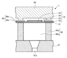
図4は、ヘッド7の補強部材68近傍を拡大した断面図を示している。補強下層68aは0.5μm程度の厚みを有する二酸化ケイ素(SiO2)によって形成されており、補強上層68bは2μm程度の厚みを有する窒化ケイ素(SiN)によって形成されている。そして補強部材68は、加圧液室66b端部の公称位置Aから実際に加工される位置A’との公差δの存在を前提として、自身が加圧液室66b端部よりも加圧液室66b側に張り出した張り出し量WOを有するように形成されている。
FIG. 4 shows an enlarged cross-sectional view of the vicinity of the reinforcing
次に、ヘッド7の動作について説明する。加圧液室66bには、図示しない供給流路を経由して供給されたインク液が充填されている。この状態において共通電極62と個別電極64との間に電圧を印加すると、圧電素子63が収縮して振動板61に図3において二点差線で示す撓み変形が発生する。この撓み変形により加圧液室66b内に体積変位が生じ、これに伴い加圧液室66b内のインク液が加圧される。加圧されたインク液はノズル板67のノズル孔67aより流出し、これによりインク液の吐出が行われる。
Next, the operation of the
次に、ヘッド7の製造工程について説明する。先ず図5に示すように、シリコン基板等からなる流路板66上に振動板61を形成する。振動板61としては、例えばシリコンオンインシュレーティングサブストレート(SOI)、あるいは二酸化ケイ素(SiO2)、窒化ケイ素(SiN)、ポリシリコン等を複数層積層成膜した構成等を選択可能である。次に図6に示すように、共通電極62、圧電素子63、個別電極64のパターニングを行い、その後全面にパッシベーション膜65を成膜することにより薄膜アクチュエータ70を構成する。共通電極62、個別電極64はチタン(Ti)、プラチナ(Pt)等から、圧電素子63はピエゾ素子(PZT)等から、パッシベーション膜65は酸化アルミニウム(Al2O3)等からそれぞれ構成される。
Next, the manufacturing process of the
さらに図7に示すように、薄膜アクチュエータ70の全面に補強下層68a及び補強上層68bを成膜した後、図8に示すように圧電素子63の近傍のみをエッチングにより選択的に除去することで補強部材68が形成される。その後図9に示すように、流路板66を薄膜アクチュエータ70が形成されている面とは反対側よりエッチングすることで流路隔壁66a及び加圧液室66bが形成され、図10に示すように流路板66にノズル板67が、補強部材68に支持フレーム69がそれぞれ接合されることによりヘッド7が完成する。
Further, as shown in FIG. 7, after a reinforcing
上述のように製造されたヘッド7では、図4に示すように加圧液室66bの端部が公称位置Aに対してばらつきである公差δを有する位置A’に加工されるが、振動板61及び共通電極62及びパッシベーション膜65を介して加圧液室66bと対向する位置にはさらに加圧液室66b側に張り出した補強部材68が存在し、補強部材68によって振動板61が実質的に変形する幅が規定されているため、流路隔壁66aによって振動板61の幅を規定する場合に比して構造コンプライアンスのばらつきが低減されている。また、補強部材68においても公称位置Bと補強下層68aが振動板61と接する位置Bとの間にばらつきが生じるが、補強上層68bを構成する窒化ケイ素(SiN)よりもヤング率が低い二酸化ケイ素(SiO2)によって補強下層68aを構成し、かつ補強上層68bの厚み2μmよりも補強下層68aの厚みを0.5μmと薄くすることにより上述のばらつきに対する曲げ剛性の感度を低減させることができ、構造コンプライアンスのばらつきをさらに低減させることができる。以下に、この理由を説明する。
In the
層数Nからなる積層板の曲げ剛性は、幅をb、ヤング率をE、ポアソン比をν、各層境界の厚み方向位置をz、各層を区別する添え字をiとすると、
(b/3)Σ[{Ei/(1−νi 2)}{(zi+1−zn)3−(zi−zn)3}]
で表される。ここで、ΣはiからNまでの総和を表す総和記号、znは積層板の曲げに関する中立軸位置であって、
zn=[Σ{Ei/(1−νi 2)×(zi+1−zi)(zi+1+zi)}]/[2Σ{Ei/(1−νi 2)×(zi+1−zi)}]
で表される。上式より、中立軸から離れた(振動板61から離れた)位置にヤング率が高くかつ厚い層を配置すると大きな曲げ剛性向上効果が得られ、逆に中立軸に近い(振動板61に近い)位置にヤング率が低くかつ薄い層を配置すると加工位置Bのばらつきに対する曲げ剛性の感度を低減させることができる。
The flexural rigidity of a laminate composed of N layers is as follows: width is b, Young's modulus is E, Poisson's ratio is ν, thickness direction position of each layer boundary is z, and a subscript for distinguishing each layer is i.
(B / 3) Σ [{E i / (1−ν i 2 )} {(z i + 1 −zn) 3 − (z i −zn) 3 }]
It is represented by Here, Σ is a sum symbol representing the sum from i to N, zn is a neutral axis position regarding the bending of the laminate,
zn = [Σ {E i / (1−ν i 2 ) × (z i + 1 −z i ) (z i + 1 + z i )}] / [2Σ {E i / (1−ν i 2 ) × (z i + 1 − z i )}]
It is represented by From the above equation, if a thick layer with a high Young's modulus is located at a position away from the neutral axis (away from the diaphragm 61), a large bending rigidity improvement effect can be obtained, and conversely close to the neutral axis (close to the
上述したように本発明によれば、振動板61の面上であって流路隔壁66aと対向する位置に流路隔壁66aよりも加圧液室66b側に突出した補強部材68を設け、補強部材68を少なくとも補強下層68aと補強上層68bとの2層を有する積層体で構成し、積層体を構成する各層68a,68bの中で最大の曲げ剛性を有する補強上層68bを振動板61に接する層以外の層とすることにより大きな曲げ剛性向上効果を得ることができ、流路隔壁66aによって振動板61の幅を規定する場合に比して構造コンプライアンスのばらつきを低減することができる。また、積層体を構成する各層68a,68bの中で最小の曲げ剛性を有する補強下層68aを振動板61に接する層とすることにより、剛性のばらつきを緩和して加工位置Bのばらつきに対する曲げ剛性の感度を低減させることができ、構造コンプライアンスのばらつきをより一層低減することができる。
As described above, according to the present invention, the reinforcing
なお、最大の曲げ剛性を有する層とは最大のヤング率を有する層または最大の厚みを有する層であり、最小の曲げ剛性を有する層とは最小のヤング率を有する層または最小の厚みを有する層であることは、上式より明らかである。上記実施形態では、積層体を構成する各層の中で最大の曲げ剛性を有する層を振動板に接する層以外の層としているが、最大の曲げ剛性を有する層は実質的な最外殻層とすることが望ましい。ここでいう実質的な最外殻層とは、コーティング等を目的として補強を目的としない薄層を含まず、補強を目的とした層の中で最外殻に位置するものをいう。 The layer having the maximum bending rigidity is a layer having the maximum Young's modulus or the layer having the maximum thickness, and the layer having the minimum bending rigidity is a layer having the minimum Young's modulus or the minimum thickness. It is clear from the above formula that it is a layer. In the above embodiment, the layer having the maximum bending rigidity among the layers constituting the laminate is a layer other than the layer in contact with the diaphragm, but the layer having the maximum bending rigidity is substantially the outermost shell layer. It is desirable to do. The substantial outermost shell layer mentioned here does not include a thin layer not intended for reinforcement for the purpose of coating or the like, and refers to a layer located in the outermost shell among the layers intended for reinforcement.
また、補強部材68に接続された支持フレーム69を設けることによりヘッド7全体の剛性をより高くすることができ、さらに支持フレーム69が補強部材68よりも小さな幅で補強部材68に接触することにより、支持フレーム69と補強部材68との接合位置ずれ等に起因する不具合現象の発生を防止することができる。
Further, by providing the
上記実施形態では、補強部材68として、補強下層68aに厚さ0.5μm程度の二酸化ケイ素(SiO2)を、補強上層68bに厚さ2.0μm程度の窒化ケイ素(SiN)を用いた2層構造のものを示したが、本発明の補強部材はこれに限定されることはなく、最大曲げ剛性を有する層が振動板61と接する層以外の層に配置されていれば、上記とは異なる層数、材質、厚みを選択してもよい。このとき最小曲げ剛性を有する層を振動板61に接する層とすることにより、構造コンプライアンスのばらつき低減効果をより好適に発揮することができる。
In the above embodiment, as the reinforcing
1 記録装置(インクジェットプリンタ)
7 液体吐出ヘッド(ヘッド)
61 振動板
66a 流路隔壁
66b 加圧液室
67a ノズル孔
68 補強部材
69 支持部材(支持フレーム)
70 変位発生手段(薄膜アクチュエータ)
1 Recording device (inkjet printer)
7 Liquid ejection head (head)
61
70 Displacement generating means (thin film actuator)
Claims (10)
前記振動板の一方の面上であって前記流路隔壁と対向する位置に配設され前記流路隔壁よりも前記加圧液室側に突出した補強部材を有し、該補強部材は少なくとも2層以上の複数層を有する積層体からなると共に、前記積層体を構成する全ての層の中で最大の曲げ剛性を有する層が前記振動板に接する層以外の層であることを特徴とする液体吐出ヘッド。 A diaphragm comprising at least a part of a plate-like flexible member, a displacement generating means for displacing the diaphragm by deformation of an electromechanical conversion element formed on one surface of the diaphragm, and the vibration A pressurizing liquid chamber connected to the other surface of the plate and partitioned by a flow path partition; and a nozzle hole communicating with the pressurizing liquid chamber, and the liquid contained in the pressurizing liquid chamber is displaced In a liquid ejection head that is pressurized by the displacement of the diaphragm generated by the generating means and ejects the pressurized liquid as droplets from the nozzle holes,
A reinforcing member disposed on one surface of the diaphragm and facing the flow path partition wall and protruding toward the pressurized liquid chamber from the flow path partition wall; A liquid comprising a laminate having a plurality of layers equal to or more than one layer, and a layer having the maximum bending rigidity among all the layers constituting the laminate is a layer other than the layer in contact with the diaphragm Discharge head.
前記最大の曲げ剛性を有する層は前記積層体を構成する全ての層の中で最大のヤング率を有する層であることを特徴とする液体吐出ヘッド。 The liquid ejection head according to claim 1,
The liquid ejection head according to claim 1, wherein the layer having the maximum bending rigidity is a layer having the maximum Young's modulus among all the layers constituting the laminate.
前記最大の曲げ剛性を有する層は前記積層体を構成する全ての層の中で最大の厚みを有する層であることを特徴とする液体吐出ヘッド。 The liquid ejection head according to claim 1,
The liquid ejection head according to claim 1, wherein the layer having the maximum bending rigidity is a layer having the maximum thickness among all the layers constituting the laminate.
前記積層体を構成する全ての層の中で最小の曲げ剛性を有する層が前記振動板に接する層であることを特徴とする液体吐出ヘッド。 The liquid discharge head according to any one of claims 1 to 3,
A liquid discharge head, wherein a layer having the minimum bending rigidity among all the layers constituting the laminate is a layer in contact with the diaphragm.
前記最小の曲げ剛性を有する層は前記積層体を構成する全ての層の中で最小のヤング率を有する層であることを特徴とする液体吐出ヘッド。 The liquid ejection head according to claim 4, wherein
The liquid discharge head according to claim 1, wherein the layer having the minimum bending rigidity is a layer having a minimum Young's modulus among all the layers constituting the laminate.
前記最小の曲げ剛性を有する層は前記積層体を構成する全ての層の中で最小の厚みを有する層であることを特徴とする液体吐出ヘッド。 The liquid ejection head according to claim 4, wherein
The liquid discharge head according to claim 1, wherein the layer having the minimum bending rigidity is a layer having a minimum thickness among all the layers constituting the laminate.
前記振動板に接する層が二酸化ケイ素からなることを特徴とする液体吐出ヘッド。 The liquid discharge head according to any one of claims 1 to 6,
A liquid discharge head, wherein a layer in contact with the diaphragm is made of silicon dioxide.
前記振動板に接する層以外の層が窒化ケイ素からなることを特徴とする液体吐出ヘッド。 The liquid discharge head according to any one of claims 1 to 7,
A liquid ejection head, wherein layers other than the layer in contact with the diaphragm are made of silicon nitride.
前記補強部材に接続された支持部材を有し、前記支持部材の前記補強部材に接続される部位の幅が前記補強部材の幅よりも小さいことを特徴とする液体吐出ヘッド。 The liquid discharge head according to any one of claims 1 to 8,
A liquid discharge head comprising: a support member connected to the reinforcing member, wherein a width of a portion of the support member connected to the reinforcing member is smaller than a width of the reinforcing member.
Priority Applications (1)
| Application Number | Priority Date | Filing Date | Title |
|---|---|---|---|
| JP2011057118A JP5754184B2 (en) | 2011-03-15 | 2011-03-15 | Liquid ejection head and recording apparatus |
Applications Claiming Priority (1)
| Application Number | Priority Date | Filing Date | Title |
|---|---|---|---|
| JP2011057118A JP5754184B2 (en) | 2011-03-15 | 2011-03-15 | Liquid ejection head and recording apparatus |
Publications (2)
| Publication Number | Publication Date |
|---|---|
| JP2012192571A true JP2012192571A (en) | 2012-10-11 |
| JP5754184B2 JP5754184B2 (en) | 2015-07-29 |
Family
ID=47084964
Family Applications (1)
| Application Number | Title | Priority Date | Filing Date |
|---|---|---|---|
| JP2011057118A Expired - Fee Related JP5754184B2 (en) | 2011-03-15 | 2011-03-15 | Liquid ejection head and recording apparatus |
Country Status (1)
| Country | Link |
|---|---|
| JP (1) | JP5754184B2 (en) |
Cited By (1)
| Publication number | Priority date | Publication date | Assignee | Title |
|---|---|---|---|---|
| JP2017100413A (en) * | 2015-12-04 | 2017-06-08 | 株式会社リコー | Discharge drive device, liquid discharge head, liquid discharge unit, and device for discharging liquid |
Citations (5)
| Publication number | Priority date | Publication date | Assignee | Title |
|---|---|---|---|---|
| JP2002011876A (en) * | 2000-06-30 | 2002-01-15 | Fujitsu Ltd | Ink jet print head and ink jet printer |
| JP2002086724A (en) * | 2000-09-19 | 2002-03-26 | Seiko Epson Corp | Ink jet recording head and ink jet recording apparatus |
| JP2008126605A (en) * | 2006-11-24 | 2008-06-05 | Seiko Epson Corp | Liquid jet head and manufacturing method thereof |
| JP2008143160A (en) * | 2006-11-14 | 2008-06-26 | Seiko Epson Corp | Liquid ejecting head, manufacturing method thereof, and liquid ejecting apparatus |
| JP2009083393A (en) * | 2007-10-02 | 2009-04-23 | Seiko Epson Corp | Liquid ejecting head, driving method thereof, and printer |
-
2011
- 2011-03-15 JP JP2011057118A patent/JP5754184B2/en not_active Expired - Fee Related
Patent Citations (5)
| Publication number | Priority date | Publication date | Assignee | Title |
|---|---|---|---|---|
| JP2002011876A (en) * | 2000-06-30 | 2002-01-15 | Fujitsu Ltd | Ink jet print head and ink jet printer |
| JP2002086724A (en) * | 2000-09-19 | 2002-03-26 | Seiko Epson Corp | Ink jet recording head and ink jet recording apparatus |
| JP2008143160A (en) * | 2006-11-14 | 2008-06-26 | Seiko Epson Corp | Liquid ejecting head, manufacturing method thereof, and liquid ejecting apparatus |
| JP2008126605A (en) * | 2006-11-24 | 2008-06-05 | Seiko Epson Corp | Liquid jet head and manufacturing method thereof |
| JP2009083393A (en) * | 2007-10-02 | 2009-04-23 | Seiko Epson Corp | Liquid ejecting head, driving method thereof, and printer |
Cited By (1)
| Publication number | Priority date | Publication date | Assignee | Title |
|---|---|---|---|---|
| JP2017100413A (en) * | 2015-12-04 | 2017-06-08 | 株式会社リコー | Discharge drive device, liquid discharge head, liquid discharge unit, and device for discharging liquid |
Also Published As
| Publication number | Publication date |
|---|---|
| JP5754184B2 (en) | 2015-07-29 |
Similar Documents
| Publication | Publication Date | Title |
|---|---|---|
| JP5862118B2 (en) | Ink jet head and recording apparatus | |
| US8534805B2 (en) | Liquid discharge head and image forming apparatus | |
| JP5618208B2 (en) | Droplet discharge head, liquid cartridge, and image forming apparatus | |
| JP2009274226A (en) | Liquid droplet ejecting head, ink cartridge, image forming apparatus, piezoelectric actuator, micropump, and light modulating device | |
| JP2014128951A (en) | Liquid droplet discharge device and image formation apparatus | |
| JP2012051236A (en) | Droplet ejecting head | |
| JP5929264B2 (en) | Droplet discharge head, ink cartridge, and image forming apparatus | |
| JP5754184B2 (en) | Liquid ejection head and recording apparatus | |
| JP2014162192A (en) | Liquid discharge head and image formation apparatus | |
| JP6237021B2 (en) | Liquid ejection head and image forming apparatus | |
| JP5895348B2 (en) | Liquid ejection head and image forming apparatus | |
| JP2013116590A (en) | Liquid droplet ejection head and image forming apparatus | |
| JP2012121199A (en) | Liquid droplet delivering head, ink cartridge and image forming apparatus | |
| JP5338585B2 (en) | Liquid ejection head and image forming apparatus | |
| JP2012139981A (en) | Liquid droplet ejection head, liquid droplet ejection apparatus, and printing apparatus | |
| JP6146177B2 (en) | Droplet discharge head, ink jet recording apparatus, and image forming apparatus | |
| JP2012076449A (en) | Droplet discharge head, ink cartridge, image forming apparatus, and method of manufacturing the droplet discharge head | |
| JP5728934B2 (en) | Head recovery device and image forming apparatus | |
| JP2012051237A (en) | Droplet discharging head, ink cartridge and image forming apparatus | |
| JP2011000738A (en) | Image forming apparatus | |
| JP2003245897A (en) | Electrostatic actuator, droplet discharge head, and ink jet recording apparatus | |
| JP2009066890A (en) | Liquid ejection head and image forming apparatus | |
| JP5310414B2 (en) | Liquid ejection head and image forming apparatus | |
| JP2010284825A (en) | Droplet discharge head, liquid cartridge, and image forming apparatus | |
| JP2007069545A (en) | Liquid ejection head and image forming apparatus |
Legal Events
| Date | Code | Title | Description |
|---|---|---|---|
| A621 | Written request for application examination |
Free format text: JAPANESE INTERMEDIATE CODE: A621 Effective date: 20140214 |
|
| A977 | Report on retrieval |
Free format text: JAPANESE INTERMEDIATE CODE: A971007 Effective date: 20141008 |
|
| A131 | Notification of reasons for refusal |
Free format text: JAPANESE INTERMEDIATE CODE: A131 Effective date: 20141014 |
|
| A521 | Written amendment |
Free format text: JAPANESE INTERMEDIATE CODE: A523 Effective date: 20141212 |
|
| TRDD | Decision of grant or rejection written | ||
| A01 | Written decision to grant a patent or to grant a registration (utility model) |
Free format text: JAPANESE INTERMEDIATE CODE: A01 Effective date: 20150428 |
|
| A61 | First payment of annual fees (during grant procedure) |
Free format text: JAPANESE INTERMEDIATE CODE: A61 Effective date: 20150511 |
|
| R151 | Written notification of patent or utility model registration |
Ref document number: 5754184 Country of ref document: JP Free format text: JAPANESE INTERMEDIATE CODE: R151 |
|
| LAPS | Cancellation because of no payment of annual fees |