JP2009066890A - Liquid jet head and image forming apparatus - Google Patents
Liquid jet head and image forming apparatus Download PDFInfo
- Publication number
- JP2009066890A JP2009066890A JP2007237356A JP2007237356A JP2009066890A JP 2009066890 A JP2009066890 A JP 2009066890A JP 2007237356 A JP2007237356 A JP 2007237356A JP 2007237356 A JP2007237356 A JP 2007237356A JP 2009066890 A JP2009066890 A JP 2009066890A
- Authority
- JP
- Japan
- Prior art keywords
- liquid chamber
- flow path
- ink supply
- common liquid
- opening
- Prior art date
- Legal status (The legal status is an assumption and is not a legal conclusion. Google has not performed a legal analysis and makes no representation as to the accuracy of the status listed.)
- Pending
Links
Images


Landscapes
- Particle Formation And Scattering Control In Inkjet Printers (AREA)
Abstract
Description
本発明は液体吐出ヘッド及び画像形成装置に関する。 The present invention relates to a liquid discharge head and an image forming apparatus.
一般に、プリンタ、ファックス、コピア、プロッタ、或いはこれらの内の複数の機能を複合した画像形成装置としては、例えば、インクの液滴を吐出する液体吐出ヘッドで構成した記録ヘッドを備え、媒体(以下「用紙」ともいうが材質を限定するものではなく、また、被記録媒体、記録媒体、転写材、記録紙なども同義で使用する。)を搬送しながら、インク滴を用紙に付着させて画像形成(記録、印刷、印写、印字も同義語で用いる。)を行なうものがある。 In general, a printer, a fax machine, a copier, a plotter, or an image forming apparatus that combines a plurality of these functions includes, for example, a recording head composed of a liquid ejection head that ejects ink droplets, It is also referred to as “paper”, but the material is not limited, and a recording medium, recording medium, transfer material, recording paper, etc. are also used synonymously.) Some perform formation (recording, printing, printing, and printing are also used synonymously).
なお、「画像形成装置」は、紙、糸、繊維、布帛、皮革、金属、プラスチック、ガラス、木材、セラミックス等の媒体に液体を吐出して画像形成を行う装置を意味し、また、「画像形成」とは、文字や図形等の意味を持つ画像を媒体に対して付与することだけでなく、パターン等の意味を持たない画像を媒体に付与する(単に液滴を吐出する)ことをも意味する。また、「インク」とは、狭義のインクに限るものではなく、吐出されるときに液体となるものであれば特に限定されるものではなく、例えば、DNA試料、レジスト、パターン材料なども含まれる。 The “image forming apparatus” means an apparatus that forms an image by discharging liquid onto a medium such as paper, thread, fiber, fabric, leather, metal, plastic, glass, wood, ceramics, etc. “Formation” means not only giving an image having a meaning such as a character or a figure to a medium but also giving an image having no meaning such as a pattern to the medium (simply ejecting a droplet). means. Further, “ink” is not limited to ink in a narrow sense, and is not particularly limited as long as it becomes liquid when ejected, and includes, for example, a DNA sample, a resist, a pattern material, and the like. .
一般的に、液体吐出ヘッドは、インクを液滴として吐出する複数設けられたノズルと、各ノズルに対して独立した個別液室と、個別液室内のインクを加圧する圧力を発生する圧力発生手段(圧電型アクチュエータ、サーマル型アクチュエータ、静電型アクチュエータなど)とを備え、個別液室内に圧力発生手段を用いて圧力を発生させ、内部に充填されているインクをノズルから液滴として吐出させる。 Generally, a liquid discharge head includes a plurality of nozzles that discharge ink as droplets, individual liquid chambers independent of each nozzle, and pressure generation means that generates pressure to pressurize ink in the individual liquid chamber (Piezoelectric actuators, thermal actuators, electrostatic actuators, etc.) are used, pressure is generated in the individual liquid chambers using pressure generating means, and the ink filled therein is ejected as droplets from the nozzles.
そして、各独立した個別液室には液体供給路を介して共通液室からインクを供給し、共通液室に外部からインク供給口を介して供給されたインクは、共通液室から各独立した個別液室内及びノズルまで分配される。 Ink is supplied from the common liquid chamber to the individual individual liquid chambers via the liquid supply path, and the ink supplied from the outside to the common liquid chamber via the ink supply port is independent from the common liquid chamber. Distributed to individual liquid chambers and nozzles.
ところで、最近では、高速記録のために記録ヘッドのノズル数が増加し、駆動周波数が高くなる傾向にあり、これによって、ノズルへの十分なインク供給量を確保するために、複数の液室に連通した共通液室の容量が拡大化しているが、この場合には容量増加に伴ってインクの充填性が難しく、気泡が共通液室の端の部分に溜まり、この気泡溜りが噴射性能(吐出性能)を著しく低下させることになり、気泡の排出性向上が問題となっている。 By the way, recently, the number of nozzles of the recording head has been increased for high-speed recording, and the drive frequency tends to be higher. As a result, in order to ensure a sufficient ink supply amount to the nozzles, a plurality of liquid chambers are provided. The capacity of the common liquid chamber that is in communication has increased, but in this case, as the capacity increases, ink filling becomes difficult, and air bubbles accumulate at the end of the common liquid chamber. Performance) is significantly reduced, and improvement in bubble discharge is a problem.
そこで、従来から、特許文献1に記載されているように、気泡排出のためのダミーノズルを共通液室端部に設けたものが知られている。また、ダミーノズルや気泡排出口ではないが、端のビットの気泡排出性を構造上向上するものとして、特許文献2には共通液室の最下流端が圧力室へのインク供給のための開口部に位置するようにすることが、特許文献3には末端のインク供給口と共通液室端との距離をインク供給口の整列間隔の1ピッチ以上離すことが記載されている。
Therefore, conventionally, as described in
上述した特許文献1に記載のように、ダミーノズルの数を増やせば気泡排出性は良化の傾向はあるが、単にダミーノズルを設けただけでは効率良く気泡を排出することはできず、ヘッドの長さも無駄に長くなるデメリットもあり、気泡による不吐出や吐出特性の低下(飛翔方向の曲がり、飛翔速度の変動、吐出滴の体積変化)を回避できないという課題がある。
As described in
また、特許文献3には吸引或いは加圧動作で除去しきれない気泡が共通液室端に溜まるため直ぐにはビットが気泡で塞がれることはないとされているものの、高周波で多ビットを駆動して液滴を吐出した場合には、溜まった気泡が移動し、ビットが気泡で塞がれ不吐出が発生してしまうため吸引動作では気泡を溜めない(残さない)構造とすることが好ましい。
Further, although
また、特許文献2に記載の構造ではインク供給口が共通液室の端に位置するため、特許文献3に記載の構造に比べると小さい気泡が溜まり難く気泡排出性は向上するが、ヘッドにインクを最初に充填する場合(初期充填時)に発生しやすい大きい気泡は排出し難く、気泡を排出するためには吸引或いは加圧動作の実施回数が多く必要となったり、非常に強力な吸引或いは加圧が必要となったりする。そのために、無駄にインクを消費してしまったり、吸引或いは加圧をする回復機構に大掛かりな機構が必要となってしまうという。
Further, in the structure described in
本発明は上記の課題に鑑みてなされたものであり、簡単な構造で気泡排出性を向上することを目的とする。 The present invention has been made in view of the above problems, and an object of the present invention is to improve bubble discharge performance with a simple structure.
上記の課題を解決するため、本発明に係る液体吐出ヘッドは、液滴を吐出する複数のノズルが連通する第1の流路と、複数のノズルの配列方向の外側に配置された気泡排出口と、気泡排出口が連通する第2の流路と、第1の流路が第1の開口部を介して連通し、第2の流路が第2の開口部を介して連通する共通液室と、を有し、共通液室と第1の流路及び第2の流路とが別部材に形成され、ノズル配列方向を幅、ノズル配列方向と直交する方向を長さとしたとき、第2の開口部の幅及び長さは、少なくとも気泡排出口と隣接する第1の流路の位置における共通液室の幅の半分以上である構成とした。
In order to solve the above problems, a liquid discharge head according to the present invention includes a first flow path in which a plurality of nozzles that discharge droplets communicate with each other, and a bubble discharge port that is disposed outside in the arrangement direction of the plurality of nozzles. And a second channel that communicates with the bubble outlet, a first channel that communicates via the first opening, and a second channel that communicates via the second opening A common liquid chamber, the first flow path, and the second flow path are formed as separate members, the width of the nozzle arrangement direction is the width, and the length orthogonal to the nozzle arrangement direction is The width and length of the
ここで、第2の開口部の第2の流路側の端は共通液室の端よりもノズル側に位置し、第2の開口部の共通液室側の端は共通液室の外側に位置する構成とできる。 Here, the end of the second opening on the second flow path side is located closer to the nozzle than the end of the common liquid chamber, and the end of the second opening on the common liquid chamber side is located outside the common liquid chamber. Can be configured.
また、第1の流路及び第2の流路を形成する流路部材と、第1の流路及び第2の流路の壁面を形成する振動板部材とを有し、流路部材及び振動板部材に形成された開口部で第1の開口部及び第2の開口部がそれぞれ構成され、流路部材の開口部の共通液室側の端が振動板部材の開口部の共通液室側の端よりもノズル側に位置する構成とできる。 A flow path member that forms the first flow path and the second flow path; and a vibration plate member that forms a wall surface of the first flow path and the second flow path. The opening formed in the plate member constitutes the first opening and the second opening, and the end of the flow channel member on the common liquid chamber side is the common liquid chamber side of the opening of the vibration plate member It can be set as the structure located in the nozzle side rather than the edge of this.
また、気泡排出口は、ノズル配列方向で第2の開口部の端よりも外側に位置する構成とできる。 In addition, the bubble discharge port can be configured to be located outside the end of the second opening in the nozzle arrangement direction.
また、第2の開口部が複数に分割され、複数の第2の開口部の総和の長さが共通液室の幅の半分以上である構成とできる。 Further, the second opening can be divided into a plurality, and the total length of the plurality of second openings can be half or more of the width of the common liquid chamber.
また、吐出する液体を供給する液体収容手段を一体に備えている構成とできる。 Moreover, it can be set as the structure which is integrally provided with the liquid storage means which supplies the liquid to discharge.
本発明に係る画像形成装置は、本発明に係る液体吐出ヘッドを備えたものである。 An image forming apparatus according to the present invention includes the liquid ejection head according to the present invention.
本発明に係る液体吐出ヘッドによれば、液滴を吐出する複数のノズルが連通する第1の流路と、複数のノズルの配列方向の外側に配置された気泡排出口と、気泡排出口が連通する第2の流路と、第1の流路が第1の開口部を介して連通し、第2の流路が第2の開口部を介して連通する共通液室と、を有し、共通液室と第1の流路及び第2の流路とが別部材に形成され、ノズル配列方向を幅、ノズル配列方向と直交する方向を長さとしたとき、第2の開口部の幅及び長さは、少なくとも気泡排出口と隣接する第1の流路の位置における共通液室の幅の半分以上である構成としたので、構造的に簡単で、気泡排出性を向上することができる。 According to the liquid discharge head according to the present invention, the first flow path through which the plurality of nozzles for discharging the droplets communicate, the bubble discharge port disposed outside the arrangement direction of the plurality of nozzles, and the bubble discharge port A second channel that communicates; a common liquid chamber in which the first channel communicates through the first opening; and the second channel communicates through the second opening. When the common liquid chamber and the first flow path and the second flow path are formed as separate members, the width of the nozzle opening direction is the width, and the length perpendicular to the nozzle arrangement direction is the width of the second opening. And the length is at least half the width of the common liquid chamber at the position of the first flow path adjacent to the bubble discharge port, so that the structure is simple and the bubble discharge property can be improved. .
本発明に係る画像形成装置によれば、本発明に係る液体吐出ヘッドを備えているので、安定した滴吐出を行って記録を行うことができる。 Since the image forming apparatus according to the present invention includes the liquid ejection head according to the present invention, it is possible to perform recording by performing stable droplet ejection.
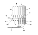
以下、本発明の実施形態について添付図面を参照して説明する。本発明の第1実施形態に係る液体吐出ヘッドの一例について図1及び図2を参照して説明する。なお、図1は同ヘッドの分解斜視説明図、図2は同ヘッドの液室長手方向に沿う断面説明図である。 Embodiments of the present invention will be described below with reference to the accompanying drawings. An example of the liquid discharge head according to the first embodiment of the present invention will be described with reference to FIGS. 1 and 2. 1 is an exploded perspective view of the head, and FIG. 2 is a cross-sectional view of the head along the longitudinal direction of the liquid chamber.
この液体吐出ヘッドは、ステンレス基板で形成した流路板1と、この流路板1の下面に接合した振動板部材2と、流路板1の上面に接合したノズル板3とを有し、これらによって液滴であるインク滴を吐出する複数のノズル4が連通する加圧液室6、加圧液室6にインクを供給するための共通液室8に第1の開口部であるインク供給口9を介して連通する第1の流路であるインク供給路7を形成している。
The liquid discharge head includes a
また、ノズル板3には複数のノズル4とともに、複数のノズル4の並び方向(ノズル配列方向)両端側には気泡排出口5が設けられており、気泡排出口5が連通するダミー液室20、ダミー液室20と連通し共通液室8に第2の開口部であるインク供給口22を介して連通する第2の流路であるインク供給路21を形成している。
In addition to the plurality of
ここで、インク供給口9は流路板1の開口部9bと第1の流路の壁面を形成する振動板部材2の開口部9aとで構成され、また、インク供給口22は流路板1の開口部22bと振動板部材2の開口部22aとで構成されている。
Here, the ink supply port 9 is constituted by the opening 9b of the
そして、振動板部材2の外面側(液室と反対面側)に各加圧液室6に対応して加圧液室6内のインクを加圧するための圧力発生手段(アクチュエータ手段)である電気機械変換素子としての積層型圧電素子12を接合し、この圧電素子12を金属あるいはセラミックスなどの高剛性材料で形成したベース基板13に接合している。積層型圧電素子12は積層型圧電素子部材をダイシングにより溝加工されており、1つ毎に圧電素子は各圧力室6と圧力室6の間とに対応するように分離されている構造となっている。ここで、圧力室6の間に対応する圧電素子は駆動せずに構造上、支柱として機能している。
And it is a pressure generation means (actuator means) for pressurizing the ink in the pressurizing
さらに、振動板部材2の外周部はハウジング部材15に接着剤にて接合している。このハウジング部材15には、共通液室8となる凹部、この共通液室8に外部からインクを供給するためのインク供給路16を形成している。なお、ここでは、インク供給路16は共通液室8の長手方向(ノズル配列方向)における略中央部に位置しているが、中央からずれた位置でもよい。ただし、インク供給路16を共通液室端に近い位置にさせた場合はインク供給路16から離れた方の共通液室端部までの距離が長くなることとなる。この場合、インク供給時に共通液室端部での流速が低下するため気泡排出が難しくなるため好ましくない。また、ハウジング部材15は、例えばエポキシ系樹脂或いはポリフェニレンサルファイトで射出成形により形成している。
Further, the outer peripheral portion of the
ここで、流路板1は、例えばステンレス基板をプレス加工することで、加圧液室6、インク供給路7となる凹部や穴部を形成したものであるが、ステンレス基板に限られるものではなく、その他のシリコン基板や感光性樹脂などをパターニング加工したものを用いることもできる。
Here, the
振動板部材2は、樹脂と金属(ここではステンレス)の2層構造のプレートから形成したもので、ステンレスをエッチング加工することで振動板領域10を形成し、プレートを貫通するインク供給口9や22は樹脂とステンレスを一括で抜くプレス加工にて形成している。なお、金属はステンレスに限られるものではなく、また、振動板2には金属板や樹脂板や金属と金属の積層部材(複層構造部材)などを用いることもできるし、加工方法も上記説明に限られるものではない。
The
ノズル板3は各加圧液室6に対応して直径10〜30μmのノズル4を形成し、流路板1に接着剤接合している。このノズル板3としては、ステンレス、ニッケルなどの金属、金属とポリイミド樹脂フィルムなどの樹脂との組み合せ、シリコン、及びそれらの組み合わせからなるものを用いることができる。ここでは、ステンレス板をプレス加工したものを用いている。また、ノズル4の内部形状(内側形状)は、断面でテーパー形状となる略円錘台形状(略円柱形状又はホーン形状でもよい。)に形成し、このノズル4の穴径はインク滴出口側の直径で約25μmとしている。
The
また、ノズル板3のノズル面(吐出方向の表面:吐出面)には、図示しない撥水性の表面処理を施した撥水処理層を設けている。撥水処理層とし、シリコーン変性フッ素樹脂(例えばオプツール)の膜を蒸着法により形成した。尚、撥水処理層にはPTFE−Ni共析メッキやフッ素樹脂の電着塗装、その他のフッ素樹脂を蒸着コートしたもの、シリコン系樹脂・フッ素系樹脂の溶剤塗布後の焼き付け等、インク物性に応じて選定した撥水処理膜を設けて、インクの滴形状、飛翔特性を安定化し、高品位の画像品質を得られるようにすることが必要である。
Further, a water repellent treatment layer having a water repellent surface treatment (not shown) is provided on the nozzle surface (surface in the ejection direction: ejection surface) of the
また、圧電素子12は、厚さ10〜50μm/1層のチタン酸ジルコン酸鉛(PZT)の圧電層と、厚さ数μm/1層の銀・パラジューム(AgPd)からなる内部電極層とを交互に積層したものであり、内部電極を交互に端面の端面電極(外部電極)である個別電極、共通電極に電気的に接続し、これらの電極にFPCケーブル17を介して駆動信号を供給するようにしている。この圧電常数がd33である圧電素子12の伸縮により加圧液室6を収縮、膨張させるようになっている。圧電素子12に駆動信号が印加され充電が行われると伸長し、また圧電素子12に充電された電荷が放電すると反対方向に収縮するようになっている。
The piezoelectric element 12 includes a lead zirconate titanate (PZT) piezoelectric layer having a thickness of 10 to 50 μm / layer and an internal electrode layer made of silver / palladium (AgPd) having a thickness of several μm / layer. The internal electrodes are alternately stacked, and the internal electrodes are alternately electrically connected to the individual electrodes and the common electrode which are the end surface electrodes (external electrodes), and a drive signal is supplied to these electrodes via the
このように構成したこの液体吐出ヘッドにおいては、例えば押し打ち方式で駆動する場合には、図示しない制御部から記録する画像に応じて複数の圧電素子12に20〜50Vの駆動パルス電圧を選択的に印加することによって、パルス電圧が印加された圧電素子12が変位して振動板部材2の変形可能領域をノズル板3方向に変形させ、液室6の容積(体積)変化によって液室6内のインクを加圧することで、ノズル板3のノズル4から液滴が吐出される。そして、液滴の吐出に伴って液室6内の圧力が低下し、このときの液流れの慣性によって液室6内には若干の負圧が発生する。この状態の下において、圧電素子12への電圧の印加をオフ状態にすることによって、振動板部材2が元の位置に戻って液室6が元の形状になるため、さらに負圧が発生する。このとき、共通液室8から液室6内にインクが充填され、次の駆動パルスの印加に応じて液滴がノズル4から吐出される。
In the liquid ejection head configured as described above, when driven by a push-off method, for example, a drive pulse voltage of 20 to 50 V is selectively applied to the plurality of piezoelectric elements 12 according to an image recorded from a control unit (not shown). Is applied to the piezoelectric element 12 to which the pulse voltage is applied to displace the deformable region of the
なお、液体吐出ヘッドは、上記の押し打ち以外にも、引き打ち方式(振動板部材2を引いた状態から開放して復元力で加圧する方式)、引き−押し打ち方式(振動板部材2を中間位置で保持しておき、この位置から引いた後、押出す方式)などの方式で駆動することもできる。
In addition to the above-described punching, the liquid discharge head is not limited to the pulling method (a method in which the vibrating
また、ここでは、各ノズル列におけるノズルピッチは150dpiとし、ノズル4の数は320個(図1では全てのノズルは示していない簡略図となっている)形成しており、ノズル列の長さは約2.13インチの長さとなっている
Also, here, the nozzle pitch in each nozzle row is 150 dpi, the number of
そこで、この液体吐出ヘッドにおける流路構造の詳細について図3をも参照して説明する。なお、図3は同ヘッドをノズル板から平面的に透過状態で見た要部平面模式的説明図である。
このヘッドにおける共通液室8は、図1に示すように、平面形状で、加圧液室6やノズル4の配列方向(ノズル配列方向と垂直方向、ここでは共通液室短手方向の共通液室の寸法を幅と表現する。)に略長方形状であり、両端部8aではR(アール)を設け液流に澱み部が少なくなるように形成している。共通液室は幅2mm、深2mmに形成し、大容量で流体抵抗が比較的低い構造となっており、高粘度のインクを高周波で駆動可能なインク供給能を有する。
The details of the flow path structure in the liquid discharge head will be described with reference to FIG. FIG. 3 is a schematic plan view of an essential part of the head viewed from the nozzle plate in a transparent state.
As shown in FIG. 1, the
そして、加圧液室6の壁面を形成する部材である振動板部材2で共通液室8の一部の壁面を形成している。インク充填時或いは回復動作時のインクの流れはインク供給口16から共通液室8へ流れ、インク供給口7、21を通り加圧液室6、ダミー液室20にインクが供給され、ノズル4及び気泡排出口5から外へ出る流れとなっている。
A part of the wall surface of the
インク供給口16は共通液室8の長手方向における略中央部に位置しており、インク供給路16から離れた共通液室8の端部では液の流速が遅く、気泡は共通液室端部に溜まりやすい。つまり、ノズル数の増加とともにヘッドが長尺化される程インク供給路16から共通液室端部までの距離が長くなり、気泡は共通液室端部に溜まりやすくなる。
The
そこで、ここでは、図3に示すように、共通液室8の短手方向の寸法を共通液室幅方向として、気泡排出口5が隣接しているノズル4へのインク供給路7の位置の共通液室幅をWとしている。インク供給口22は、振動板部材2の開口部22a、流路板1の開口部22bにより構成される開口部となり、その幅w及び長さLは、共通液室8の幅Wに対してその半分以上、即ち、W/2以上に形成されている。
Therefore, here, as shown in FIG. 3, the dimension of the
気泡は安定する状態である球形に近付くように形成される。大きいもので共通液室8の幅W相当の大きさになるが、その気泡の端部は共通液室8に接するように溜まろうとする。気泡の端部と中心をインク供給口22が含むようにすることで吸引或いは加圧による回復動作時に幅Wに近い直径を有する大きな気泡の排出性が格段に向上する。
The bubbles are formed so as to approach a spherical shape which is a stable state. Although it is large, it becomes a size corresponding to the width W of the
つまり、気泡排出口に通じるインク供給口22は、共通液室8内で共通液室8の幅Wを直径とする気泡が形成されたとき、その気泡の中心位置がインク供給口22内に位置する幅及び長さに形成するということである。
That is, the
また、上述したように、ノズルピッチは150dpiでノズル数は160個、つまりノズル列の長さが約1インチのヘッドの場合、インク供給口16を前述したように共通液室8の略中央に配置すると、共通液室端までの距離が0.5インチ程度の距離となる。この場合、インク供給口22は、幅W1、長さLはW/2未満でも気泡排出性による不吐出の発生確率は低いが、これは共通液室端部での流速が速いことにより気泡が排出されやすくなるためである。ノズル数320個でノズル列の長さが約2インチのヘッドではインク供給口16を共通液室8の略中央に配置した場合でも共通液室端までの距離が1インチ程度の距離となり、共通液室端部での流速を確保することが難しく、インク供給口22の幅w及び長さLが共通液室8の幅Wに対してその半分未満(W/2未満)であると、共通液室端部の大きな気泡を排出することが難しくなる。
As described above, in the case of a head having a nozzle pitch of 150 dpi and a nozzle number of 160, that is, a nozzle row having a length of about 1 inch, the
次に、インク供給口9を構成している振動板部材2の開口部9a、流路板1の開口部9bと、インク供給口22を構成している振動板部材2の開口部22a、流路板1の開口部22bの関係について図3と共に図4をも参照して説明する。なお、図4は図3のA−A線に沿う断面図である。
ここでは、流路板1の開口部9bの後端9beが振動板部材2の開口部9aの内側、即ちノズル4側に位置するように、また、流路板1の開口部22bの後端22beが振動板部材2の開口部22aの内側、即ちノズル4側に位置するように構成している。
Next, the
Here, the rear end 9be of the
このように、流路板1の開口部9b、22bの後端が振動板部材2の開口部9a、22aの後端よりもの内側に位置する構成にすることにより、図4のX部における液流の澱みが少なくなり、気泡が流路にトラップし難くなる。
As described above, the rear ends of the
このように、共通液室とノズルに連通する第1の流路及び気泡排出口に連通する第2の流路とが別部材に形成され、ノズル配列方向を幅、ノズル配列方向と直交する方向を長さとしたとき、第2の開口部の幅及び長さは、少なくとも気泡排出口と隣接する第1の流路の位置における共通液室の幅の半分以上である構成とすることで、気泡の排出性が向上する。 Thus, the common liquid chamber, the first flow path communicating with the nozzle and the second flow path communicating with the bubble discharge port are formed in separate members, the nozzle arrangement direction is a width, and the direction orthogonal to the nozzle arrangement direction The width and length of the second opening are at least half the width of the common liquid chamber at the position of the first flow path adjacent to the bubble discharge port. Emissions are improved.
次に、本発明の第2実施形態について図5を参照して説明する。なお、図5は図3と同様なヘッドをノズル板から平面的に透過状態で見た要部平面模式的説明図である。
ここでは、インク供給口22は、インク供給路21側の端22Cを共通液室8の短手方向の端よりもノズル4側に位置し、共通液室8の長手方向の端22Dを共通液室8の長手方向の端よりも外側に位置するように形成している。
Next, a second embodiment of the present invention will be described with reference to FIG. FIG. 5 is a schematic plan view of an essential part of a head similar to that shown in FIG. 3 viewed from the nozzle plate in a transparent state.
Here, in the
これによって、共通液室8の端部における長手方向端部8bや短手方向端部8cの部分で微小な気泡も溜まることなく排出される。
As a result, minute bubbles are discharged without accumulating at the end portion 8b in the longitudinal direction and the end portion 8c in the short direction at the end portion of the
つまり、微小な気泡は共通液室端部8b、8c部に留まっている場合には吐出特性への影響はほとんどないが、圧力室6へ侵入した場合には吐出特性の低下(飛翔方向の曲がり、飛翔速度の変動、吐出滴の体積変化)を引き起こしてしまう。また、微小な気泡が多数結合したり、成長したりすることにより大きな気泡を形成してしまい、不吐出(吐出不能)を引き起こしてしまうこともあり、その場合は、画像の不良だけでなく回復させるために回復動作を実施することが必要となり無駄にインクを消費してしまうことになる。
That is, when the minute bubbles remain at the common liquid chamber end portions 8b and 8c, there is almost no influence on the discharge characteristics, but when they enter the
この実施形態のように微小な気泡も残さないように排出することにより、上述のような気泡による不具合の発生を防ぐことができ、更に信頼性を向上することができる。 By discharging so as not to leave minute bubbles as in this embodiment, it is possible to prevent the occurrence of defects due to the bubbles as described above, and to further improve the reliability.
次に、本発明の第3実施形態について図6を参照して説明する。なお、図6は図3と同様なヘッドをノズル板から平面的に透過状態で見た要部平面模式的説明図である。
ここでは、気泡排出口5の位置がノズル配列方向で開口部22の外側に位置する構成としている。このように構成することで、液の流れがスムーズであるため気泡排出性が向上する。また、隣接するノズル4と離れるためインク充填時や回復動作時に気泡排出口5から排出された気泡が泡状となり、隣接するノズル4を覆ってしまいノズル4が吐出不良を起こすおそれを低減できる。
Next, a third embodiment of the present invention will be described with reference to FIG. 6 is a schematic plan view of an essential part of a head similar to that shown in FIG. 3 as viewed from the nozzle plate in a transparent state.
Here, the position of the
次に、本発明の第4実施形態について図7を参照して説明する。なお、図7は図3と同様なヘッドをノズル板から平面的に透過状態で見た要部平面模式的説明図である。
ここでは、気泡排出口5、インク供給路21、インク供給口22を複数列設けている。つまり、第2の開口部が複数に分割された構成としている。そして、1つのインク供給口22の幅Xを開口部9の幅と同じにするとともに、複数のインク供給口22(これをインク供給口群22Gという。)の幅の総和を前述したように共通液室8の幅Wの半分以上としている。
Next, a fourth embodiment of the present invention will be described with reference to FIG. 7 is a schematic plan view of an essential part of a head similar to FIG. 3 viewed from the nozzle plate in a transparent state.
Here, a plurality of rows of
このように、インク供給口群22Gの幅及び長さを共通液室8の幅の半分以上に形成することにより、共通液室8の端部に溜まると共通液室幅相当の大きい気泡の端部から中心をインク供給口群22Gが含むようにすることで、吸引或いは加圧による回復動作時に大きな気泡の排出性を向上することができる。また、インク供給口群22Gはインク供給口9の開口幅xが同じであるために、エッチング加工で開口する場合に寸法制御しやすい。
In this way, by forming the width and length of the ink
次に、本発明の第5実施形態について図8を参照して説明する。なお、図8は図3と同様なヘッドをノズル板から平面的に透過状態で見た要部平面模式的説明図である。
ここでは、インク供給路7とインク供給路21とが、インク供給口9とインク供給口22とが、ノズル4と気泡排出口5とが、それぞれ同じ形状に形成されている。つまり、同じ流路形状を繰り返した構造としている。これにより、プレス加工で流路を形成するときに容易に加工することができる。
Next, a fifth embodiment of the present invention will be described with reference to FIG. FIG. 8 is a schematic plan view of an essential part of a head similar to that shown in FIG. 3 viewed from the nozzle plate in a transparent state.
Here, the
なお、図示しないが、上述した各実施形態の液体吐出ヘッドにインクを供給する液体収容手段としてのインクタンクを一体化し、所謂インクカートリッジとすることもできる。これにより、ヘッド一体型インクカートリッジ(又はタンク一体型ヘッド)における、気泡の排出性が向上し、不吐出が発生し難く、初期充填性や回復性を向上できる。 Although not shown, an ink tank serving as a liquid storage unit that supplies ink to the liquid discharge heads of the above-described embodiments may be integrated to form a so-called ink cartridge. Thereby, in the head-integrated ink cartridge (or tank-integrated head), the bubble discharge property is improved, non-ejection hardly occurs, and the initial filling property and recoverability can be improved.
また、上記実施形態では、液滴を吐出させる圧力を発生する圧力発生手段(アクチュエータ手段、エネルギー発生手段などとも称される。)として圧電素子を用いるヘッドについて説明したが、その他、発熱抵抗体などの電気熱変換素子を用いて液体の膜沸騰による相変化を利用するサーマル型アクチュエータ、温度変化による金属相変化を用いる形状記憶合金アクチュエータ、静電力を用いる静電アクチュエータなどを使用する液体吐出ヘッドにも適用することができる。 In the above embodiment, a head using a piezoelectric element as pressure generating means (also referred to as actuator means, energy generating means, etc.) for generating pressure for ejecting droplets has been described. For a liquid discharge head using a thermal actuator that uses a phase change caused by film boiling of a liquid using an electrothermal transducer, a shape memory alloy actuator that uses a metal phase change caused by a temperature change, an electrostatic actuator that uses an electrostatic force, etc. Can also be applied.
次に、本発明に係る液体吐出ヘッドを搭載する画像形成装置の一例について図9及び図10を参照して説明する。
この画像形成装置はシリアル型画像形成装置であり、左右の側板201A、201Bに横架したガイド部材である主従のガイドロッド231、232でキャリッジ233を主走査方向に摺動自在に保持し、図示しない主走査モータによってタイミングベルトを介して矢示方向(キャリッジ主走査方向)に移動走査する。
Next, an example of an image forming apparatus equipped with the liquid ejection head according to the present invention will be described with reference to FIGS.
This image forming apparatus is a serial type image forming apparatus, and a
このキャリッジ233には、イエロー(Y)、シアン(C)、マゼンタ(M)、ブラック(K)の各色のインク滴を吐出するための本発明に係る液体吐出ヘッドからなる記録ヘッド234a、234b(区別しないときは「記録ヘッド234」という。)を複数のノズルからなるノズル列を主走査方向と直交する副走査方向に配列し、インク滴吐出方向を下方に向けて装着している。
The
記録ヘッド234は、それぞれ2つのノズル列を有し、記録ヘッド234aの一方のノズル列はブラック(K)の液滴を、他方のノズル列はシアン(C)の液滴を、記録ヘッド234bの一方のノズル列はマゼンタ(M)の液滴を、他方のノズル列はイエロー(Y)の液滴を、それぞれ吐出する。なお、ここでは2ヘッド構成で4色の液滴を吐出する構成としているが、各色毎の記録ヘッドを備えることもできるし、4色の液滴を吐出する複数のノズルを並べたノズル列を有する1つの記録ヘッド構成とすることもできる。
Each of the recording heads 234 has two nozzle rows. One nozzle row of the
また、キャリッジ233には、記録ヘッド234のノズル列に対応して各色のインクを供給するためのサブタンク235a、235b(区別しないときは「サブタンク235」という。)を搭載している。このサブタンク235には各色の供給チューブ236を介して、供給ユニット224によって各色のインクカートリッジ210から各色のインクが補充供給される。
The
一方、給紙トレイ202の用紙積載部(圧板)241上に積載した用紙242を給紙するための給紙部として、用紙積載部241から用紙242を1枚ずつ分離給送する半月コロ(給紙コロ)243及び給紙コロ243に対向し、摩擦係数の大きな材質からなる分離パッド244を備え、この分離パッド244は給紙コロ243側に付勢されている。
On the other hand, as a paper feeding unit for feeding the
そして、この給紙部から給紙された用紙242を記録ヘッド234の下方側に送り込むために、用紙242を案内するガイド部材245と、カウンタローラ246と、搬送ガイド部材247と、先端加圧コロ249を有する押さえ部材248とを備えるとともに、給送された用紙242を静電吸着して記録ヘッド234に対向する位置で搬送するための搬送手段である搬送ベルト251を備えている。
In order to feed the
この搬送ベルト251は、無端状ベルトであり、搬送ローラ252とテンションローラ253との間に掛け渡されて、ベルト搬送方向(副走査方向)に周回するように構成している。また、この搬送ベルト251の表面を帯電させるための帯電手段である帯電ローラ256を備えている。この帯電ローラ256は、搬送ベルト251の表層に接触し、搬送ベルト251の回動に従動して回転するように配置されている。この搬送ベルト251は、図示しない副走査モータによってタイミングを介して搬送ローラ252が回転駆動されることによってベルト搬送方向に周回移動する。
The
さらに、記録ヘッド234で記録された用紙242を排紙するための排紙部として、搬送ベルト251から用紙242を分離するための分離爪261と、排紙ローラ262及び排紙コロ263とを備え、排紙ローラ262の下方に排紙トレイ203を備えている。
Further, as a paper discharge unit for discharging the
また、装置本体の背面部には両面ユニット271が着脱自在に装着されている。この両面ユニット271は搬送ベルト251の逆方向回転で戻される用紙242を取り込んで反転させて再度カウンタローラ246と搬送ベルト251との間に給紙する。また、この両面ユニット271の上面は手差しトレイ272としている。
A double-
さらに、キャリッジ233の走査方向一方側の非印字領域には、記録ヘッド234のノズルの状態を維持し、回復するための回復手段を含む本発明に係るヘッドの維持回復装置である維持回復機構281を配置している。この維持回復機構281には、記録ヘッド234の各ノズル面をキャピングするための各キャップ部材(以下「キャップ」という。)282a、282b(区別しないときは「キャップ282」という。)と、ノズル面をワイピングするためのブレード部材であるワイパーブレード283と、増粘した記録液を排出するために記録に寄与しない液滴を吐出させる空吐出を行うときの液滴を受ける空吐出受け284などを備えている。
Further, a maintenance /
また、キャリッジ233の走査方向他方側の非印字領域には、記録中などに増粘した記録液を排出するために記録に寄与しない液滴を吐出させる空吐出を行うときの液滴を受ける液体回収容器であるインク回収ユニット(空吐出受け)288を配置し、このインク回収ユニット288には記録ヘッド234のノズル列方向に沿った開口部289などを備えている。
In addition, in the non-printing area on the other side in the scanning direction of the
このように構成したこの画像形成装置においては、給紙トレイ202から用紙242が1枚ずつ分離給紙され、略鉛直上方に給紙された用紙242はガイド245で案内され、搬送ベルト251とカウンタローラ246との間に挟まれて搬送され、更に先端を搬送ガイド237で案内されて先端加圧コロ249で搬送ベルト251に押し付けられ、略90°搬送方向を転換される。
In this image forming apparatus configured as described above, the
このとき、帯電ローラ256に対してプラス出力とマイナス出力とが交互に繰り返すように、つまり交番する電圧が印加され、搬送ベルト251が交番する帯電電圧パターン、すなわち、周回方向である副走査方向に、プラスとマイナスが所定の幅で帯状に交互に帯電されたものとなる。このプラス、マイナス交互に帯電した搬送ベルト251上に用紙242が給送されると、用紙242が搬送ベルト251に吸着され、搬送ベルト251の周回移動によって用紙242が副走査方向に搬送される。
At this time, a positive output and a negative output are alternately applied to the charging
そこで、キャリッジ233を移動させながら画像信号に応じて記録ヘッド234を駆動することにより、停止している用紙242にインク滴を吐出して1行分を記録し、用紙242を所定量搬送後、次の行の記録を行う。記録終了信号又は用紙242の後端が記録領域に到達した信号を受けることにより、記録動作を終了して、用紙242を排紙トレイ203に排紙する。
Therefore, by driving the
このように、この画像形成装置では本発明に係る液体吐出ヘッドを備えているので、気泡による吐出不良が少なく、安定した記録を行うことができる。 As described above, since the image forming apparatus includes the liquid ejection head according to the present invention, ejection failure due to bubbles is small, and stable recording can be performed.
なお、上記実施形態では本発明をプリンタ構成の画像形成装置に適用した例で説明したが、これに限るものではなく、例えば、プリンタ/ファックス/コピア複合機などの画像形成装置に適用することができる。また、狭義のインク以外の液体や定着処理液などを用いる画像形成装置にも適用することができる。また、上記実施形態ではシリアル型画像形成装置に適用した例で説明しているが、ライン型液体吐出ヘッドやライン型画像形成装置にも同様に適用することができる。 In the above embodiment, the present invention has been described with reference to an example in which the present invention is applied to an image forming apparatus having a printer configuration. However, the present invention is not limited to this. For example, the present invention may be applied to an image forming apparatus such as a printer / fax / copier multifunction machine. it can. Further, the present invention can be applied to an image forming apparatus using a liquid other than the narrowly defined ink, a fixing processing liquid, or the like. In the above-described embodiment, the example is described in which the present invention is applied to a serial type image forming apparatus. However, the present invention can be similarly applied to a line type liquid discharge head and a line type image forming apparatus.
1…流路板
2…振動板部材
3…ノズル板
4…ノズル
5…気泡排出口
6…個別液室
8…共通液室
9…インク供給口
12…圧電素子
20…ダミー液室
21…インク供給路
234…記録ヘッド(液体吐出ヘッド)
DESCRIPTION OF
Claims (7)
前記複数のノズルの配列方向の外側に配置された気泡排出口と、
前記気泡排出口が連通する第2の流路と、
前記第1の流路が第1の開口部を介して連通し、前記第2の流路が第2の開口部を介して連通する共通液室と、を有し、
前記共通液室と前記第1の流路及び第2の流路とが別部材に形成され、
前記ノズル配列方向を幅、前記ノズル配列方向と直交する方向を長さとしたとき、前記第2の開口部の幅及び長さは、少なくとも前記気泡排出口と隣接する第1の流路の位置における前記共通液室の幅の半分以上である
ことを特徴とする液体吐出ヘッド。 A first flow path through which a plurality of nozzles for discharging droplets communicate;
A bubble discharge port disposed outside the array direction of the plurality of nozzles;
A second flow path through which the bubble discharge port communicates;
A common liquid chamber in which the first flow path communicates via a first opening, and the second flow path communicates via a second opening;
The common liquid chamber and the first flow path and the second flow path are formed in separate members,
When the nozzle arrangement direction is a width and the direction orthogonal to the nozzle arrangement direction is a length, the width and length of the second opening are at least at the position of the first flow path adjacent to the bubble discharge port. A liquid discharge head characterized by being at least half the width of the common liquid chamber.
Priority Applications (1)
| Application Number | Priority Date | Filing Date | Title |
|---|---|---|---|
| JP2007237356A JP2009066890A (en) | 2007-09-13 | 2007-09-13 | Liquid jet head and image forming apparatus |
Applications Claiming Priority (1)
| Application Number | Priority Date | Filing Date | Title |
|---|---|---|---|
| JP2007237356A JP2009066890A (en) | 2007-09-13 | 2007-09-13 | Liquid jet head and image forming apparatus |
Publications (1)
| Publication Number | Publication Date |
|---|---|
| JP2009066890A true JP2009066890A (en) | 2009-04-02 |
Family
ID=40603671
Family Applications (1)
| Application Number | Title | Priority Date | Filing Date |
|---|---|---|---|
| JP2007237356A Pending JP2009066890A (en) | 2007-09-13 | 2007-09-13 | Liquid jet head and image forming apparatus |
Country Status (1)
| Country | Link |
|---|---|
| JP (1) | JP2009066890A (en) |
Cited By (2)
| Publication number | Priority date | Publication date | Assignee | Title |
|---|---|---|---|---|
| JP2013063532A (en) * | 2011-09-15 | 2013-04-11 | Ricoh Co Ltd | Droplet ejection head and droplet ejection device |
| JP2013193231A (en) * | 2012-03-16 | 2013-09-30 | Ricoh Co Ltd | Liquid discharge head and image forming apparatus |
-
2007
- 2007-09-13 JP JP2007237356A patent/JP2009066890A/en active Pending
Cited By (3)
| Publication number | Priority date | Publication date | Assignee | Title |
|---|---|---|---|---|
| JP2013063532A (en) * | 2011-09-15 | 2013-04-11 | Ricoh Co Ltd | Droplet ejection head and droplet ejection device |
| EP2570263B1 (en) * | 2011-09-15 | 2020-05-27 | Ricoh Company, Ltd. | Liquid-jet head and liquid-jet head device |
| JP2013193231A (en) * | 2012-03-16 | 2013-09-30 | Ricoh Co Ltd | Liquid discharge head and image forming apparatus |
Similar Documents
| Publication | Publication Date | Title |
|---|---|---|
| JP4869108B2 (en) | Liquid ejection head, liquid cartridge, and image forming apparatus | |
| JP5754188B2 (en) | Liquid ejection head and image forming apparatus | |
| JP2007307774A (en) | Liquid delivering head, liquid delivering apparatus, and image forming apparatus | |
| JP4906537B2 (en) | Liquid ejection head and image forming apparatus | |
| JP2011056922A (en) | Liquid discharging head, and image forming apparatus | |
| JP5004497B2 (en) | Liquid ejection head, liquid ejection apparatus, and image forming apparatus | |
| JP5500017B2 (en) | Liquid ejection head and image forming apparatus | |
| JP4876046B2 (en) | Liquid ejection head and image forming apparatus | |
| JP5327435B2 (en) | Liquid discharge head, method for manufacturing the same, and image forming apparatus | |
| JP2014172259A (en) | Liquid discharge head and image formation apparatus | |
| JP5943292B2 (en) | Liquid ejection head, image forming apparatus, and liquid ejection head manufacturing method | |
| JP5549163B2 (en) | Liquid ejection head and image forming apparatus | |
| JP2012171113A (en) | Ink jet head, droplet discharge device and image forming device | |
| JP4938604B2 (en) | Liquid ejection head and image forming apparatus | |
| JP2009066890A (en) | Liquid jet head and image forming apparatus | |
| JP5338585B2 (en) | Liquid ejection head and image forming apparatus | |
| JP2009066904A (en) | Liquid jet head and image forming apparatus | |
| JP4961373B2 (en) | Liquid ejection head and image forming apparatus | |
| JP5857559B2 (en) | Liquid ejection head and image forming apparatus | |
| JP5338715B2 (en) | Liquid ejection head and image forming apparatus | |
| JP2012192707A (en) | Liquid ejecting head and image forming apparatus | |
| JP2008062483A (en) | Liquid delivering head and image forming apparatus | |
| JP2009178966A (en) | Liquid discharge head and image forming apparatus | |
| JP5310414B2 (en) | Liquid ejection head and image forming apparatus | |
| JP2007307777A (en) | Liquid delivering head, liquid delivering apparatus and image forming device |