JP2012192558A - Tandem taper box molding apparatus - Google Patents

Tandem taper box molding apparatus Download PDF

Info

Publication number
JP2012192558A
JP2012192558A JP2011056756A JP2011056756A JP2012192558A JP 2012192558 A JP2012192558 A JP 2012192558A JP 2011056756 A JP2011056756 A JP 2011056756A JP 2011056756 A JP2011056756 A JP 2011056756A JP 2012192558 A JP2012192558 A JP 2012192558A
Authority
JP
Japan
Prior art keywords
bottom piece
male mold
piece
side pieces
molding
Prior art date
Legal status (The legal status is an assumption and is not a legal conclusion. Google has not performed a legal analysis and makes no representation as to the accuracy of the status listed.)
Granted
Application number
JP2011056756A
Other languages
Japanese (ja)
Other versions
JP5822221B2 (en
Inventor
Osamu Setoguchi
修 瀬戸口
Current Assignee (The listed assignees may be inaccurate. Google has not performed a legal analysis and makes no representation or warranty as to the accuracy of the list.)
Metal Creation Co Ltd
Original Assignee
Metal Creation Co Ltd
Priority date (The priority date is an assumption and is not a legal conclusion. Google has not performed a legal analysis and makes no representation as to the accuracy of the date listed.)
Filing date
Publication date
Application filed by Metal Creation Co Ltd filed Critical Metal Creation Co Ltd
Priority to JP2011056756A priority Critical patent/JP5822221B2/en
Publication of JP2012192558A publication Critical patent/JP2012192558A/en
Application granted granted Critical
Publication of JP5822221B2 publication Critical patent/JP5822221B2/en
Active legal-status Critical Current
Anticipated expiration legal-status Critical

Links

Images

Landscapes

  • Making Paper Articles (AREA)

Abstract

PROBLEM TO BE SOLVED: To provide an apparatus that can speedily and reliably form a tandem taper box, even when using a low strength material.SOLUTION: A molding apparatus 100 includes: a first male die 30 that includes a first protrusion 34 and adsorbs a bottom piece of a sheet-like material 9 to a first bottom piece abutment surface 31a by air suction; a second male die 40 that includes a second protrusion 44 and adsorbs a bottom piece of a sheet-like material 9 to a second bottom piece abutment surface 41a by air suction; a supporting member 50 that supports movably the first male die 30 and the second male die 40 in a longitudinal direction between an initial position and a molding position, and movably the first male die 30 and the second male die 40 in an approaching and alienating direction in a horizontal direction; a first guide member 70 that has a first guide groove 71 to which the first protrusion 34 engages; a second guide member 80 that has a second guide groove 81 to which the second protrusion 44 engages; and a female die frame 90 that abuts the side piece of the sheet-like material 9, folds to the bottom piece and forms a tandem taper box 1.

Description

本発明は、連結型テーパ箱(底片および底片に連なる側片を有し、底片よりも開口部の方が大きくなるように側片が傾斜した複数個のテーパ箱が互いに側片の開口側端部で連結されたもの)を成形する装置に関する。   The present invention relates to a connecting type tapered box (a bottom piece and a side piece connected to the bottom piece, and a plurality of tapered boxes whose side pieces are inclined so that the opening is larger than the bottom piece. And the like are connected to each other.

従来、底片よりも開口部の方が大きくなるように側片が傾斜したテーパ箱を成形する装置が知られている。例えば、特許文献1に記載の如くである。
特許文献1に記載の装置は、テーパ箱たる容器の素材(紙等のシート状物を所定の形状に切り出したもの)を上下から型押しするための上型(雄型)および下型(雌型)を具備する。特許文献1に記載の装置は容器の素材を下型に対して所定の位置に固定し、次いで上型を下型に押しつけ、容器の素材を上型および下型の形状に沿って変形させる(折り曲げる)ことにより、容器を成形する。
しかし、特許文献1に記載の装置は容器の種類(形状)毎に専用の上型および下型を用意する必要がある。そのため、特許文献1に記載の装置を用いて少量他品種生産を行う(複数種類の容器を少量ずつ生産する)場合には、容器の種類毎の上型および下型を製造するコストが大きくなり、ひいては容器の製造コストが増大する。
また、特許文献1に記載の装置は成形後の容器を上型および下型から取り外し、上型および下型から離れた位置まで搬送し、容器を複数個積層して保管する作業を要する。
そのため、これらの作業に対応する装置を別途用意する必要があり、装置が全体として大型化および複雑化し、設備コストが増大する。
2. Description of the Related Art Conventionally, there is known an apparatus for forming a tapered box whose side pieces are inclined so that an opening is larger than a bottom piece. For example, as described in Patent Document 1.
The apparatus described in Patent Document 1 includes an upper mold (male mold) and a lower mold (female) for embossing a material of a container that is a tapered box (a sheet-like material such as paper cut into a predetermined shape) from above and below. Mold). The apparatus described in Patent Document 1 fixes the material of the container at a predetermined position with respect to the lower mold, then presses the upper mold against the lower mold, and deforms the material of the container along the shapes of the upper mold and the lower mold ( The container is formed by bending.
However, the apparatus described in Patent Document 1 needs to prepare a dedicated upper mold and lower mold for each type (shape) of the container. Therefore, in the case of producing a small amount of other varieties using the apparatus described in Patent Document 1 (producing a plurality of types of containers little by little), the cost of manufacturing the upper mold and the lower mold for each type of container increases. As a result, the manufacturing cost of the container increases.
Further, the apparatus described in Patent Document 1 requires a work of removing the molded containers from the upper mold and the lower mold, transporting them to a position away from the upper mold and the lower mold, and stacking and storing a plurality of containers.
For this reason, it is necessary to separately prepare an apparatus corresponding to these operations, the apparatus becomes larger and complicated as a whole, and the equipment cost increases.

上記問題を解消する装置としては特許文献2に記載の装置が知られている。
特許文献2に記載の装置は、テーパ函の素材である紙函素材を下方から上方に向かって押し上げる雄型と、雄型の上方に配置されて雄型とともに紙函素材を変形させる(折り曲げる)とともに成形後のテーパ函を複数個積層して収容する雌型枠と、を具備する。
特許文献2に記載の装置の場合、雌型枠の内部空間の寸法を調整(変更)することが可能である。そのため、特許文献2に記載の装置を用いて少量他品種生産を行う場合にはテーパ函の種類毎に雄型のみを交換すれば良く、雌型枠については交換する必要がない。
また、雌型枠はテーパ函を複数個積層して収容する機能を有するため、成形後のテーパ函を取り出し、別の場所に搬送し、改めて複数個積層して収容するといった作業を省略することが可能である。
As an apparatus for solving the above problem, an apparatus described in Patent Document 2 is known.
The apparatus described in Patent Document 2 is a male mold that pushes up a paper box material that is a taper box material from below, and a male mold that is disposed above the male mold and deforms (folds) the paper box material together with the male mold. And a female mold frame for accommodating a plurality of molded taper boxes in a stacked manner.
In the case of the apparatus described in Patent Document 2, it is possible to adjust (change) the size of the internal space of the female mold. Therefore, when producing a small amount of other varieties using the apparatus described in Patent Document 2, it is only necessary to replace the male mold for each type of taper box, and it is not necessary to replace the female mold frame.
In addition, since the female mold has a function of stacking and storing a plurality of taper boxes, the work of taking out the formed taper box, transporting it to another place, and stacking and storing a plurality of taper boxes again is omitted. Is possible.

また、近年では、底片および底面に連なる側片を有し、底片よりも開口部の方が大きくなるように側片が傾斜した複数のテーパ箱が互いに側片の開口側端部で連結されたものである連結型テーパ箱を成形する装置も知られている。例えば、特許文献3に記載の如くである。
特許文献3に記載の装置は、連結型テーパ箱たる函蓋付きテーパ函の素材である紙函素材を下方から上方に向かって押し上げる雄型と、雄型の上方に配置されて雄型とともに紙函素材を変形させる(折り曲げる)とともに成形後の函蓋付きテーパ函を複数個積層して収容する雌型枠と、雌型枠の内部および外部との間で移動可能であり、雌型枠の内部に配置されているときに紙函素材の身函部と函蓋部との連結部分を押さえる可動押さえ体と、を具備する。
特許文献3に記載の装置は、可動押さえ体を備えることにより、特許文献1および特許文献2に記載の装置をそのまま用いたのでは成形することが困難であった連結型テーパ箱を成形することが可能である。
しかし、特許文献3に記載の装置は、連結型テーパ箱を成形する速度を増大させる(単位時間当たりの連結型テーパ箱の成形個数を増大させる)ことが困難である、という問題を有する。
より詳細には、特許文献3に記載の装置の場合、可動押さえ体が紙函素材の身函部と函蓋部との連結部分に当接した状態を保持しつつ雄型を雌型枠に押し込むことにより、身函部の底片と函蓋部の底片とを互いに接近させつつ側片(側片)を折り曲げる必要がある。
しかし、連結型テーパ箱を成形する速度が大きい場合には可動押さえ体が紙函素材の身函部と函蓋部との連結部分に位置精度良く当接した状態を保持することが困難となり、可動押さえ体が身函部と函蓋部との連結部分からずれた位置に当接する場合がある。
その結果、紙函素材を所望の位置で折り曲げることができず、成形後の連結型テーパ箱の寸法精度が低下する(成形後の連結型テーパ箱の形状が崩れてしまう)場合がある。
また、特許文献3に記載の装置は、可動押さえ体と身函部と函蓋部との連結部分との当接部位に外周部が尖った形状の押さえローラを当接させるので、紙函素材を構成する材料があまり強度が高くないもの(例えば、薄手の紙等)である場合には、連結型テーパ箱を成形するときに紙函素材が破れたり、紙函素材にシワが発生したりする場合がある。
Further, in recent years, a plurality of tapered boxes having side pieces connected to the bottom piece and the bottom face, and the side pieces inclined so that the opening portion is larger than the bottom piece, are connected to each other at the opening side end portions of the side pieces. An apparatus for forming a connected tapered box is also known. For example, as described in Patent Document 3.
The apparatus described in Patent Document 3 includes a male mold that pushes up a paper box material that is a material of a taper box with a box lid, which is a connected taper box, and a paper that is disposed above the male mold and that is paper with the male mold. The box material is deformed (folded) and can be moved between a female mold frame that houses a plurality of taper boxes with a box lid after molding, and the inside and outside of the female mold frame. And a movable pressing body that presses a connecting portion between the body box portion of the paper box material and the box lid portion when arranged inside.
The apparatus described in Patent Document 3 is provided with a movable pressing body, thereby forming a connection type tapered box that was difficult to be molded if the apparatuses described in Patent Document 1 and Patent Document 2 were used as they were. Is possible.
However, the apparatus described in Patent Document 3 has a problem that it is difficult to increase the speed of forming the connection type tapered box (increase the number of connection type taper boxes formed per unit time).
More specifically, in the case of the apparatus described in Patent Document 3, the male mold is changed to the female mold frame while maintaining the state where the movable presser body is in contact with the connecting portion between the body portion and the lid portion of the paper box material. By pushing in, it is necessary to bend the side piece (side piece) while bringing the bottom piece of the box part and the bottom piece of the box cover part close to each other.
However, when the speed of forming the connection type taper box is high, it becomes difficult to maintain the state in which the movable presser body is in contact with the connection part between the body part of the paper box material and the cover part with high positional accuracy. There is a case where the movable pressing body comes into contact with a position deviated from a connecting portion between the body part and the box cover part.
As a result, the paper box material cannot be folded at a desired position, and the dimensional accuracy of the connected tapered box after molding may be reduced (the shape of the connected tapered box after molding may be broken).
Moreover, since the apparatus described in Patent Document 3 causes a pressing roller having a sharp outer peripheral portion to come into contact with the contact portion between the movable pressing body, the body portion, and the connecting portion of the box cover portion, the paper box material If the material that makes up the box is not very strong (for example, thin paper), the paper box material may be torn or wrinkles may occur when forming the connected taper box. There is a case.

特開昭50−161376号公報JP-A-50-161376 特開平6−23871号公報JP-A-6-23871 特開平6−106657号公報JP-A-6-106657

本発明は以上の如き状況に鑑みてなされたものである。
すなわち、本発明が解決しようとする課題は、従来よりも強度が低い素材を用いた場合でも連結型テーパ箱を高速かつ確実に成形することが可能な連結型テーパ箱成形装置を提供すること、である。
The present invention has been made in view of the above situation.
That is, the problem to be solved by the present invention is to provide a connected taper box forming apparatus capable of forming a connected taper box at high speed and reliably even when using a material having lower strength than the conventional one. It is.

以下では、上記課題を解決するための手段を説明する。   Hereinafter, means for solving the above problems will be described.

即ち、請求項1においては、
第一底片と、一端部が前記第一底片の端部に連結される複数の第一側片と、第二底片と、一端部が前記第二底片の端部に連結される複数の第二側片と、を具備し、前記複数の第一側片の一つにおける他端部と前記複数の第二側片の一つにおける他端部とが連結されるシート状物を出発材とし、前記出発材における前記第一底片と前記複数の第一側片との連結部分、前記第二底片と前記複数の第二側片との連結部分、および前記複数の第一側片の一つにおける他端部と前記複数の第二側片の一つにおける他端部との連結部分を折り曲げることにより、前記第一底片および前記複数の第一側片で囲まれるとともに前記第一底片よりも大きい開口部を有する第一収容部が形成された第一テーパ箱、並びに前記第二底片および前記複数の第二側片で囲まれるとともに前記第二底片よりも大きい開口部を有する第二収容部が形成された第二テーパ箱を備えるとともに前記複数の第一側片の一つにおける他端部と前記複数の第二側片の一つにおける他端部との連結部分において前記第一テーパ箱および第二テーパ箱が連結されたものである連結型テーパ箱を成形する連結型テーパ箱成形装置であって、
成形後の前記第一底片に対応する第一底片当接面および成形後の複数の第一側片に対応する複数の第一側片当接面を有する第一本体部と、前記第一本体部に固定される第一突起と、を備え、所定の位置決め位置に位置決めされた前記出発材の第一底片をエア吸引により前記第一底片当接面に吸着可能な第一雄型と、
成形後の前記第二底片に対応する第二底片当接面および成形後の複数の第二側片に対応する複数の第二側片当接面を有する第二本体部と、前記第二本体部に固定される第二突起と、を備え、前記所定の位置決め位置に位置決めされた前記出発材の第二底片をエア吸引により前記第二底片当接面に吸着可能な第二雄型と、
前記所定の位置決め位置に位置決めされた出発材の第一底片に前記第一底片当接面が対向するとともに前記所定の位置決め位置に位置決めされた出発材の第二底片に前記第二底片当接面が対向する位置である初期位置と、前記所定の位置決め位置を挟んで前記初期位置の反対側となる位置である成形位置と、の間で前記第一雄型および前記第二雄型を前記初期位置から前記成形位置に向かう方向である突出方向および前記成形位置から前記初期位置に向かう方向である退避方向に移動可能、かつ、前記突出方向および前記退避方向に垂直な方向において前記第一雄型および前記第二雄型を相対的に接近および離間する方向に移動可能に支持する支持部材と、
第一ガイド溝が形成され、前記第一ガイド溝には前記第一突起が嵌合する第一ガイド部材と、
第二ガイド溝が形成され、前記第二ガイド溝には前記第二突起が嵌合する第二ガイド部材と、
前記第一雄型および前記第二雄型に吸引された状態で前記成形位置まで移動した前記出発材の前記複数の第一側片および前記複数の第二側片に当接し、前記複数の第一側片および前記複数の第二側片をそれぞれ前記第一底片および前記第二底片に対して折り曲げて前記複数の第一側片当接面および前記複数の第二側片当接面に当接させることにより前記連結型テーパ箱を成形する雌型枠と、
を具備し、
前記突出方向および前記退避方向に垂直な方向における前記第一ガイド溝から前記第二ガイド溝までの距離である溝間距離は、前記突出方向に向かうに従って小さくなるものである。
That is, in claim 1,
A first bottom piece, a plurality of first side pieces whose one end is connected to the end of the first bottom piece, a second bottom piece, and a plurality of second ones whose one end is connected to the end of the second bottom piece. And a side piece, and a starting material is a sheet-like material in which the other end of one of the plurality of first side pieces and the other end of one of the plurality of second side pieces are connected, One of the connecting portion between the first bottom piece and the plurality of first side pieces in the starting material, the connecting portion between the second bottom piece and the plurality of second side pieces, and one of the plurality of first side pieces. Bending the connecting portion between the other end and the other end of one of the plurality of second side pieces is surrounded by the first bottom piece and the plurality of first side pieces and is larger than the first bottom piece. Surrounded by a first tapered box formed with a first housing portion having an opening, and the second bottom piece and the plurality of second side pieces. And having a second taper box formed with a second accommodating portion having an opening larger than the second bottom piece, and the other end portion and the plurality of second side pieces in one of the plurality of first side pieces. A connecting type taper box forming apparatus for forming a connecting type taper box in which the first taper box and the second taper box are connected in a connecting portion with the other end in one of the above,
A first body portion having a first bottom piece contact surface corresponding to the first bottom piece after molding and a plurality of first side piece contact surfaces corresponding to the plurality of first side pieces after molding; A first male mold that is capable of adsorbing the first bottom piece of the starting material positioned at a predetermined positioning position to the first bottom piece contact surface by air suction,
A second body portion having a second bottom piece contact surface corresponding to the second bottom piece after molding and a plurality of second side piece contact surfaces corresponding to the plurality of second side pieces after molding; A second protrusion fixed to the portion, and a second male die capable of adsorbing the second bottom piece of the starting material positioned at the predetermined positioning position to the second bottom piece contact surface by air suction,
The first bottom piece contact surface faces the first bottom piece of the starting material positioned at the predetermined positioning position, and the second bottom piece contact surface faces the second bottom piece of the starting material positioned at the predetermined positioning position. Between the initial position, which is a position facing each other, and the molding position, which is a position opposite to the initial position across the predetermined positioning position, the first male mold and the second male mold The first male mold is movable in a protruding direction that is a direction from the position toward the molding position and a retracting direction that is a direction from the molding position toward the initial position, and in a direction perpendicular to the protruding direction and the retracting direction. And a support member that movably supports the second male mold in a direction approaching and separating from the second male mold,
A first guide groove is formed, and the first guide member into which the first protrusion is fitted in the first guide groove;
A second guide groove is formed, and a second guide member into which the second protrusion is fitted in the second guide groove;
Abutting against the plurality of first side pieces and the plurality of second side pieces of the starting material moved to the molding position while being sucked by the first male mold and the second male mold; The one side piece and the plurality of second side pieces are bent with respect to the first bottom piece and the second bottom piece, respectively, and contact the plurality of first side piece contact surfaces and the plurality of second side piece contact surfaces. A female mold for forming the connected taper box by contact;
Comprising
An inter-groove distance, which is a distance from the first guide groove to the second guide groove in a direction perpendicular to the protruding direction and the retracting direction, becomes smaller toward the protruding direction.

請求項2においては、
第一底片と、一端部が前記第一底片の端部に連結される複数の第一側片と、第二底片と、一端部が前記第二底片の端部に連結される複数の第二側片と、を具備し、前記複数の第一側片の一つにおける他端部と前記複数の第二側片の一つにおける他端部とが連結されるシート状物を出発材とし、前記出発材における前記第一底片と前記複数の第一側片との連結部分、前記第二底片と前記複数の第二側片との連結部分、および前記複数の第一側片の一つにおける他端部と前記複数の第二側片の一つにおける他端部との連結部分を折り曲げることにより、前記第一底片および前記複数の第一側片で囲まれるとともに前記第一底片よりも大きい開口部を有する第一収容部が形成された第一テーパ箱、並びに前記第二底片および前記複数の第二側片で囲まれるとともに前記第二底片よりも大きい開口部を有する第二収容部が形成された第二テーパ箱を備えるとともに前記複数の第一側片の一つにおける他端部と前記複数の第二側片の一つにおける他端部との連結部分において前記第一テーパ箱および第二テーパ箱が連結されたものである連結型テーパ箱を成形する連結型テーパ箱成形装置であって、
成形後の前記第一底片に対応する第一底片当接面および成形後の複数の第一側片に対応する複数の第一側片当接面を有する第一本体部を備え、所定の位置決め位置に位置決めされた前記出発材の第一底片をエア吸引により前記第一底片当接面に吸着可能な第一雄型と、
成形後の前記第二底片に対応する第二底片当接面および成形後の複数の第二側片に対応する複数の第二側片当接面を有する第二本体部と、前記第二本体部に固定される嵌合突起と、を備え、前記所定の位置決め位置に位置決めされた前記出発材の第二底片をエア吸引により前記第二底片当接面に吸着可能な第二雄型と、
前記所定の位置決め位置に位置決めされた出発材の第一底片に前記第一底片当接面が対向するとともに前記所定の位置決め位置に位置決めされた出発材の第二底片に前記第二底片当接面が対向する位置である初期位置と、前記所定の位置決め位置を挟んで前記初期位置の反対側となる位置である成形位置と、の間で前記第一雄型および前記第二雄型を前記初期位置から前記成形位置に向かう方向である突出方向および前記成形位置から前記初期位置に向かう方向である退避方向に移動可能に支持し、かつ、前記第二雄型を前記第一雄型に対して前記突出方向および前記退避方向に垂直な方向において接近および離間する方向に移動可能に支持する支持部材と、
嵌合ガイド溝が形成され、前記嵌合ガイド溝には前記嵌合突起が嵌合する嵌合ガイド部材と、
前記第一雄型および前記第二雄型に吸引された状態で前記成形位置まで移動した前記出発材の前記複数の第一側片および前記複数の第二側片に当接し、前記複数の第一側片および前記複数の第二側片をそれぞれ前記第一底片および前記第二底片に対して折り曲げて前記複数の第一側片当接面および前記複数の第二側片当接面に当接させることにより前記連結型テーパ箱を成形する雌型枠と、
を具備し、
前記嵌合ガイド溝は、前記突出方向および前記退避方向、並びに前記第二雄型が前記第一雄型に対して接近および離間する方向に対して垂直な方向から見たとき、前記突出方向に向かうに従って前記第一雄型に接近する方向に延びているものである。
In claim 2,
A first bottom piece, a plurality of first side pieces whose one end is connected to the end of the first bottom piece, a second bottom piece, and a plurality of second ones whose one end is connected to the end of the second bottom piece. And a side piece, and a starting material is a sheet-like material in which the other end of one of the plurality of first side pieces and the other end of one of the plurality of second side pieces are connected, One of the connecting portion between the first bottom piece and the plurality of first side pieces in the starting material, the connecting portion between the second bottom piece and the plurality of second side pieces, and one of the plurality of first side pieces. Bending the connecting portion between the other end and the other end of one of the plurality of second side pieces is surrounded by the first bottom piece and the plurality of first side pieces and is larger than the first bottom piece. Surrounded by a first tapered box formed with a first housing portion having an opening, and the second bottom piece and the plurality of second side pieces. And having a second taper box formed with a second accommodating portion having an opening larger than the second bottom piece, and the other end portion and the plurality of second side pieces in one of the plurality of first side pieces. A connecting type taper box forming apparatus for forming a connecting type taper box in which the first taper box and the second taper box are connected in a connecting portion with the other end in one of the above,
A first body portion having a first bottom piece contact surface corresponding to the first bottom piece after molding and a plurality of first side piece contact surfaces corresponding to the plurality of first side pieces after molding; A first male mold capable of adsorbing the first bottom piece of the starting material positioned at a position to the first bottom piece contact surface by air suction;
A second body portion having a second bottom piece contact surface corresponding to the second bottom piece after molding and a plurality of second side piece contact surfaces corresponding to the plurality of second side pieces after molding; A second male mold capable of adsorbing the second bottom piece of the starting material positioned at the predetermined positioning position to the second bottom piece abutment surface by air suction,
The first bottom piece contact surface faces the first bottom piece of the starting material positioned at the predetermined positioning position, and the second bottom piece contact surface faces the second bottom piece of the starting material positioned at the predetermined positioning position. Between the initial position, which is a position facing each other, and the molding position, which is a position opposite to the initial position across the predetermined positioning position, the first male mold and the second male mold The second male mold is supported with respect to the first male mold so as to be movable in a protruding direction that is a direction from the position toward the molding position and a retracting direction that is a direction from the molding position toward the initial position. A support member that is movably supported in a direction approaching and separating in a direction perpendicular to the protruding direction and the retracting direction;
A fitting guide groove is formed, and a fitting guide member into which the fitting protrusion fits in the fitting guide groove;
Abutting against the plurality of first side pieces and the plurality of second side pieces of the starting material moved to the molding position while being sucked by the first male mold and the second male mold; The one side piece and the plurality of second side pieces are bent with respect to the first bottom piece and the second bottom piece, respectively, and contact the plurality of first side piece contact surfaces and the plurality of second side piece contact surfaces. A female mold for forming the connected taper box by contact;
Comprising
The fitting guide groove is formed in the protruding direction when viewed from the direction perpendicular to the protruding direction and the retracting direction, and the direction in which the second male mold approaches and separates from the first male mold. As it goes, it extends in a direction approaching the first male mold.

本発明は、従来よりも強度が低い素材を用いた場合でも連結型テーパ箱を高速かつ確実に成形することが可能である、という効果を奏する。   The present invention has an effect that a connected tapered box can be formed at high speed and surely even when a material having a lower strength than before is used.

本発明に係る連結型テーパ箱成形装置の第一実施形態を示す左側面図。The left view which shows 1st embodiment of the connection type taper box shaping | molding apparatus which concerns on this invention. 本発明に係る連結型テーパ箱成形装置の第一実施形態を示す要部平面図。The principal part top view which shows 1st embodiment of the connection type taper box forming apparatus which concerns on this invention. 本発明に係る連結型テーパ箱成形装置の第一実施形態を示す要部左側面図。The principal part left view which shows 1st embodiment of the connection type taper box shaping | molding apparatus which concerns on this invention. 第一雄型および第二雄型の実施の一形態を示す正面図。The front view which shows one Embodiment of a 1st male type | mold and a 2nd male type | mold. (a)第一ガイド部材および第二ガイド部材の実施の一形態を示す左前上方から見た斜視図、(b)第一ガイド部材および第二ガイド部材の実施の一形態を示す平面図。(A) The perspective view seen from upper left front which shows one Embodiment of a 1st guide member and a 2nd guide member, (b) The top view which shows one Embodiment of a 1st guide member and a 2nd guide member. (a)連結型テーパ箱の第一実施形態の出発材を示す平面図、(b)連結型テーパ箱の第一実施形態を示す斜視図。(A) The top view which shows the starting material of 1st embodiment of a connection type taper box, (b) The perspective view which shows 1st embodiment of a connection type taper box. 連結型テーパ箱の第一実施形態が成形される過程を示す斜視図。The perspective view which shows the process in which 1st embodiment of a connection type taper box is shape | molded. 本発明に係る連結型テーパ箱成形装置の第二実施形態を示す左側面図。The left view which shows 2nd embodiment of the connection type taper box shaping | molding apparatus which concerns on this invention. 本発明に係る連結型テーパ箱成形装置の第二実施形態を示す要部平面図。The principal part top view which shows 2nd embodiment of the connection type taper box shaping | molding apparatus which concerns on this invention. 第一雄型および第二雄型の別実施形態を示す正面図。The front view which shows another embodiment of a 1st male type | mold and a 2nd male type | mold. (a)連結型テーパ箱の第二実施形態の出発材を示す平面図、(b)連結型テーパ箱の第二実施形態を示す斜視図。(A) The top view which shows the starting material of 2nd embodiment of a connection type taper box, (b) The perspective view which shows 2nd embodiment of a connection type taper box. (a)連結型テーパ箱の第三実施形態の出発材を示す平面図、(b)連結型テーパ箱の第三実施形態を示す斜視図。(A) The top view which shows the starting material of 3rd embodiment of a connection type taper box, (b) The perspective view which shows 3rd embodiment of a connection type taper box.

以下では、図面を参照して本発明に係る連結型テーパ箱成形装置の実施の第一実施形態である成形装置100について説明する。
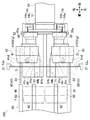
図1に示す成形装置100は、図6の(a)に示すシート状物9を出発材とし、シート状物9を適宜折り曲げることにより図6の(b)に示す連結型テーパ箱1を成形する装置である。
Below, with reference to drawings, the shaping | molding apparatus 100 which is 1st embodiment of implementation of the connection type taper box shaping | molding apparatus which concerns on this invention is demonstrated.
The forming apparatus 100 shown in FIG. 1 forms the connected tapered box 1 shown in FIG. 6B by using the sheet-like material 9 shown in FIG. 6A as a starting material and bending the sheet-like material 9 as appropriate. It is a device to do.

なお、以下では便宜上、図1に示す成形装置100に対して互いに垂直な方向として「上下方向」、「前後方向」および「左右方向」を定義し、これらの方向を用いて成形装置100を構成する各部材について説明する。   In the following, for convenience, “vertical direction”, “front-rear direction” and “left-right direction” are defined as directions perpendicular to the molding apparatus 100 shown in FIG. 1, and the molding apparatus 100 is configured using these directions. Each member to be described will be described.

シート状物9は本発明に係るシート状物の第一実施形態であり、連結型テーパ箱1の出発材(原材料)となるものである。本実施形態のシート状物9は薄手の段ボール紙に打ち抜き加工を施すことにより所定の形状に切り出したシート状(平板状)の部材であり、一対の板面(表面および裏面)を有する。
本実施形態の場合、シート状物9が後述する「成形装置100における所定の位置決め位置」に配置されたときにはシート状物9の一対の板面のうち、表面が前方を向き、裏面が後方に向いている。
なお、「成形装置100における所定の位置決め位置」は、成形装置100がシート状物9を出発材として連結型テーパ箱1を成形するための基準となる位置である。
The sheet-like material 9 is a first embodiment of the sheet-like material according to the present invention, and serves as a starting material (raw material) of the connection type tapered box 1. The sheet-like material 9 of the present embodiment is a sheet-like (flat plate-like) member cut into a predetermined shape by punching thin cardboard paper, and has a pair of plate surfaces (front surface and back surface).
In the case of the present embodiment, when the sheet-like object 9 is arranged at a “predetermined positioning position in the molding apparatus 100” described later, the surface of the pair of plate surfaces of the sheet-like object 9 faces frontward and the backside faces rearward. It is suitable.
The “predetermined positioning position in the forming apparatus 100” is a position that serves as a reference for the forming apparatus 100 to form the connected tapered box 1 using the sheet-like object 9 as a starting material.

図6の(a)に示す如く、シート状物9は第一底片2a、四つの第一側片2b・2c・2d・2e、四つの第一固定片2f・2g・2h・2i、第二底片3a、四つの第二側片3b・3c・3d・3eおよび四つの第二固定片3f・3g・3h・3iを備える。
なお、以下では便宜上、シート状物9が後述する「所定の位置決め位置」に配置されたときの姿勢と、先に定義した「上下方向」、「前後方向」および「左右方向」とを対応させてシート状物9の形状を説明する。
As shown in FIG. 6A, the sheet-like material 9 includes a first bottom piece 2a, four first side pieces 2b, 2c, 2d, and 2e, four first fixed pieces 2f, 2g, 2h, and 2i, a second piece. A bottom piece 3a, four second side pieces 3b, 3c, 3d, and 3e and four second fixed pieces 3f, 3g, 3h, and 3i are provided.
In the following, for the sake of convenience, the posture when the sheet-like object 9 is arranged at a “predetermined positioning position” described later is associated with the previously defined “vertical direction”, “front / rear direction”, and “left / right direction”. The shape of the sheet-like material 9 will be described.

第一底片2aは本発明に係る第一底片の実施の一形態である。本実施形態の第一底片2aは一対の板面(表面および裏面)の形状が正方形である板状の部分である。   The first bottom piece 2a is an embodiment of the first bottom piece according to the present invention. The first bottom piece 2a of the present embodiment is a plate-like portion in which the shape of a pair of plate surfaces (front surface and back surface) is a square.

四つの第一側片2b・2c・2d・2eは本発明に係る複数の第一側片の実施の一形態である。本実施形態の四つの第一側片2b・2c・2d・2eは一対の板面(表面および裏面)の形状が概ね台形である板状の部分である。
四つの第一側片2b・2c・2d・2eはそれぞれ一端部(台形の上底および台形のうち、短い方の底辺に対応する端部)が第一底片2aの右端部、上端部、左端部および下端部に連結されている。
第一底片2aと四つの第一側片2b・2c・2d・2eとの連結部分には、シート状物9を薄手の段ボール紙から切り出すときに合わせて型押しすることによりシート状物9の裏面側から表面側に向かって窪んだ筋(図6の(a)における点線参照)が形成され、これらの連結部分を山折りする(シート状物9の表面側に向かって凸となるように折り曲げること)を容易としている。
The four first side pieces 2b, 2c, 2d, and 2e are one embodiment of a plurality of first side pieces according to the present invention. The four first side pieces 2b, 2c, 2d, and 2e of the present embodiment are plate-like portions in which the shape of a pair of plate surfaces (front surface and back surface) is substantially trapezoidal.
Each of the four first side pieces 2b, 2c, 2d, and 2e has one end (the end corresponding to the shorter base of the trapezoid upper base and trapezoid) at the right end, upper end, and left end of the first bottom piece 2a. And are connected to the lower end.
At the connecting portion of the first bottom piece 2a and the four first side pieces 2b, 2c, 2d, and 2e, the sheet-like material 9 is embossed when the sheet-like material 9 is cut out from the thin corrugated cardboard. A streak (see the dotted line in FIG. 6A) formed from the back side to the front side is formed, and these connecting portions are folded in a mountain (to protrude toward the front side of the sheet-like object 9). Easy to bend).

四つの第一固定片2f・2g・2h・2iはそれぞれ第一側片2bの上端部、第一側片2dの上端部、第一側片2dの下端部および第一側片2bの下端部に連結されている。
第一側片2bと第一固定片2fとの連結部分、第一側片2dと第一固定片2gとの連結部分、第一側片2dと第一固定片2hとの連結部分、および第一側片2bと第一固定片2iとの連結部分には、シート状物9の裏面側から表面側に向かって窪んだ筋(図6の(a)における点線参照)が形成され、これらの連結部分を山折りする(シート状物9の表面側に向かって凸となるように折り曲げること)を容易としている。
The four first fixed pieces 2f, 2g, 2h, and 2i are respectively an upper end portion of the first side piece 2b, an upper end portion of the first side piece 2d, a lower end portion of the first side piece 2d, and a lower end portion of the first side piece 2b. It is connected to.
A connection portion between the first side piece 2b and the first fixed piece 2f, a connection portion between the first side piece 2d and the first fixed piece 2g, a connection portion between the first side piece 2d and the first fixed piece 2h, and In the connecting portion between the one side piece 2b and the first fixed piece 2i, a streak (see the dotted line in FIG. 6A) formed from the back side to the front side of the sheet-like material 9 is formed. The connecting portion is easily folded in a mountain (folded so as to be convex toward the surface side of the sheet-like object 9).

第二底片3aは本発明に係る第二底片の実施の一形態である。本実施形態の第二底片3aは一対の板面(表面および裏面)の形状が正方形である板状の部分である。   The second bottom piece 3a is an embodiment of the second bottom piece according to the present invention. The 2nd bottom piece 3a of this embodiment is a plate-shaped part whose shape of a pair of plate surface (front surface and back surface) is a square.

四つの第二側片3b・3c・3d・3eは本発明に係る複数の第二側片の実施の一形態である。本実施形態の四つの第二側片3b・3c・3d・3eは一対の板面(表面および裏面)の形状が概ね台形である板状の部分である。
四つの第二側片3b・3c・3d・3eはそれぞれ一端部(台形の上底および台形のうち、短い方の底辺に対応する端部)が第二底片3aの左端部、上端部、右端部および下端部に連結されている。
第二底片3aと四つの第二側片3b・3c・3d・3eとの連結部分にはシート状物9の裏面側から表面側に向かって窪んだ筋(図6の(a)における点線参照)が形成され、これらの連結部分を山折りする(シート状物9の表面側に向かって凸となるように折り曲げること)を容易としている。
The four second side pieces 3b, 3c, 3d, and 3e are one embodiment of a plurality of second side pieces according to the present invention. The four second side pieces 3b, 3c, 3d, and 3e of the present embodiment are plate-like portions in which the shape of a pair of plate surfaces (front surface and back surface) is substantially trapezoidal.
Each of the four second side pieces 3b, 3c, 3d, and 3e has one end (the end corresponding to the shorter base of the trapezoid upper base and trapezoid), the left end, the upper end, and the right end of the second bottom piece 3a. And are connected to the lower end.
In the connecting portion of the second bottom piece 3a and the four second side pieces 3b, 3c, 3d, and 3e, a streak recessed from the back side to the front side of the sheet-like material 9 (see the dotted line in FIG. 6A) ) Is formed, and it is easy to fold these connecting portions in a mountain (bend so as to be convex toward the surface side of the sheet-like object 9).

四つの第二固定片3f・3g・3h・3iはそれぞれ第二側片3bの上端部、第二側片3cの右端部、第二側片3eの右端部および第二側片3bの下端部に連結されている。
第二側片3bと第二固定片3fとの連結部分、第二側片3cと第二固定片3gとの連結部分、第二側片3eと第二固定片3hとの連結部分、および第二側片3bと第二固定片3iとの連結部分には、シート状物9の裏面側から表面側に向かって窪んだ筋(図6の(a)における点線参照)が形成され、これらの連結部分を山折りする(シート状物9の表面側に向かって凸となるように折り曲げること)を容易としている。
The four second fixed pieces 3f, 3g, 3h, and 3i are respectively an upper end portion of the second side piece 3b, a right end portion of the second side piece 3c, a right end portion of the second side piece 3e, and a lower end portion of the second side piece 3b. It is connected to.
A connecting portion between the second side piece 3b and the second fixing piece 3f, a connecting portion between the second side piece 3c and the second fixing piece 3g, a connecting portion between the second side piece 3e and the second fixing piece 3h, and a first In the connecting portion between the two side pieces 3b and the second fixed piece 3i, streaks (see dotted lines in FIG. 6A) that are recessed from the back side to the front side of the sheet-like object 9 are formed. The connecting portion is easily folded in a mountain (folded so as to be convex toward the surface side of the sheet-like object 9).

図6の(a)に示す如く、シート状物9の四つの第一側片2b・2c・2d・2eの一つである第一側片2bにおける他端部(右端部)と、四つの第二側片3b・3c・3d・3eの一つである第二側片3bにおける他端部(左端部)と、は連結されている。
第一側片2bにおける他端部(右端部)と第二側片3bにおける他端部(左端部)との連結部分には、シート状物9の表面側から裏面側に向かって窪んだ筋(図6の(a)における二点鎖線参照)が形成され、これらの連結部分を谷折りする(シート状物9の裏面側に向かって凸となるように折り曲げること)を容易としている。
As shown in FIG. 6A, the other end (right end) of the first side piece 2b, which is one of the four first side pieces 2b, 2c, 2d, and 2e of the sheet-like material 9, The other end (left end) of the second side piece 3b that is one of the second side pieces 3b, 3c, 3d, and 3e is connected.
In the connecting portion between the other end portion (right end portion) of the first side piece 2b and the other end portion (left end portion) of the second side piece 3b, streaks that are recessed from the front surface side to the back surface side of the sheet-like object 9. (Refer to the two-dot chain line in FIG. 6A), and it is easy to fold these connecting portions (bend so as to be convex toward the back side of the sheet-like material 9).

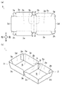
図6の(b)に示す連結型テーパ箱1は、出発材となるシート状物9に以下の(i)から(iii)の作業を施すことにより、成形される。
(i)第一底片2aと四つの第一側片2b・2c・2d・2eとの連結部分、第一側片2bと第一固定片2fとの連結部分、第一側片2dと第一固定片2gとの連結部分、第一側片2dと第一固定片2hとの連結部分、第一側片2bと第一固定片2iとの連結部分、第二底片3aと四つの第二側片3b・3c・3d・3eとの連結部分、第二側片3bと第二固定片3fとの連結部分、第二側片3cと第二固定片3gとの連結部分、第二側片3eと第二固定片3hとの連結部分および第二側片3bと第二固定片3iとの連結部分が山折りされる。
(ii)第一側片2bにおける他端部(右端部)と第二側片3bにおける他端部(左端部)との連結部分が谷折りされる。
(iii)第一固定片2fおよび第一側片2cの右端部、第一固定片2gおよび第一側片2cの左端部、第一固定片2hおよび第一側片2eの左端部、第一固定片2iおよび第一側片2eの右端部、第二固定片3fおよび第二側片3cの左端部、第二固定片3gおよび第二側片3dの上端部、第二固定片3hおよび第二側片3dの下端部、並びに第二固定片3iおよび第二側片3eの左端部を接着する。
The connection type taper box 1 shown in FIG. 6B is formed by performing the following operations (i) to (iii) on the sheet-like material 9 as a starting material.
(I) A connecting portion between the first bottom piece 2a and the four first side pieces 2b, 2c, 2d, and 2e, a connecting portion between the first side piece 2b and the first fixed piece 2f, and the first side piece 2d and the first Connection part with fixed piece 2g, connection part between first side piece 2d and first fixed piece 2h, connection part between first side piece 2b and first fixed piece 2i, second bottom piece 3a and four second sides A connecting portion between the pieces 3b, 3c, 3d, and 3e, a connecting portion between the second side piece 3b and the second fixing piece 3f, a connecting portion between the second side piece 3c and the second fixing piece 3g, and the second side piece 3e. And the connecting portion between the second fixed piece 3h and the connecting portion between the second side piece 3b and the second fixed piece 3i are mountain-folded.
(Ii) The connecting portion between the other end (right end) of the first side piece 2b and the other end (left end) of the second side piece 3b is valley-folded.
(Iii) The right end of the first fixed piece 2f and the first side piece 2c, the left end of the first fixed piece 2g and the first side piece 2c, the left end of the first fixed piece 2h and the first side piece 2e, the first The right end of the fixed piece 2i and the first side piece 2e, the left end of the second fixed piece 3f and the second side piece 3c, the upper end of the second fixed piece 3g and the second side piece 3d, the second fixed piece 3h and the second The lower end portion of the second side piece 3d and the left end portions of the second fixed piece 3i and the second side piece 3e are bonded.

図6の(b)に示す連結型テーパ箱1は本発明に係る連結型テーパ箱の第一実施形態である。連結型テーパ箱1は第一テーパ箱2および第二テーパ箱3を備える。   A connected tapered box 1 shown in FIG. 6B is a first embodiment of a connected tapered box according to the present invention. The connected taper box 1 includes a first taper box 2 and a second taper box 3.

第一テーパ箱2は第一底片2a、四つの第一側片2b・2c・2d・2eおよび四つの第一固定片2f・2g・2h・2iを有する。
第一テーパ箱2には、第一底片2aおよび四つの第一側片2b・2c・2d・2eで囲まれる空間である第一収容部2jが形成される。第一収容部2jは四つの第一側片2b・2c・2d・2eの他端部を周縁とする開口部を有する。第一収容部2jの開口部は、第一底片2aの一対の板面に垂直な方向から見て第一底片2aよりも大きい。
従って、第一収容部2j、ひいては第一テーパ箱2は第一底片2aから第一収容部2jの開口部に向かって拡径した(テーパした)概ね四角錐台形状を有する。
The first taper box 2 has a first bottom piece 2a, four first side pieces 2b, 2c, 2d, and 2e and four first fixed pieces 2f, 2g, 2h, and 2i.
The first taper box 2 is formed with a first accommodating portion 2j that is a space surrounded by the first bottom piece 2a and the four first side pieces 2b, 2c, 2d, and 2e. The 1st accommodating part 2j has the opening part which makes the other end part of the four 1st side pieces 2b * 2c * 2d * 2e a periphery. The opening part of the 1st accommodating part 2j is larger than the 1st bottom piece 2a seeing from a direction perpendicular | vertical to a pair of plate surface of the 1st bottom piece 2a.
Therefore, the first accommodating portion 2j, and thus the first tapered box 2, has a substantially quadrangular pyramid shape that is expanded (tapered) from the first bottom piece 2a toward the opening of the first accommodating portion 2j.

第二テーパ箱3は第二底片3a、四つの第二側片3b・3c・3d・3eおよび四つの第二固定片3f・3g・3h・3iを有する。
第二テーパ箱3には、第二底片3aおよび四つの第二側片3b・3c・3d・3eで囲まれる空間である第二収容部3jが形成される。第二収容部3jは四つの第二側片3b・3c・3d・3eの他端部を周縁とする開口部を有する。第二収容部3jの開口部は、第二底片3aの一対の板面に垂直な方向から見て第二底片3aよりも大きい。
従って、第二収容部3j、ひいては第二テーパ箱3は第二底片3aから第二収容部3jの開口部に向かって拡径した(テーパした)概ね四角錐台形状を有する。
The second taper box 3 has a second bottom piece 3a, four second side pieces 3b, 3c, 3d, and 3e and four second fixed pieces 3f, 3g, 3h, and 3i.
The second taper box 3 is formed with a second accommodating portion 3j that is a space surrounded by the second bottom piece 3a and the four second side pieces 3b, 3c, 3d, and 3e. The 2nd accommodating part 3j has an opening part which makes the other end part of four 2nd side piece 3b * 3c * 3d * 3e a periphery. The opening of the second accommodating portion 3j is larger than the second bottom piece 3a when viewed from the direction perpendicular to the pair of plate surfaces of the second bottom piece 3a.
Accordingly, the second accommodating portion 3j, and thus the second tapered box 3, has a generally quadrangular pyramid shape that is expanded (tapered) from the second bottom piece 3a toward the opening of the second accommodating portion 3j.

連結型テーパ箱1は第一側片2bにおける他端部(右端部)と第二側片3bにおける他端部(左端部)との連結部分において第一テーパ箱2および第二テーパ箱3が連結されたものである。
本実施形態の連結型テーパ箱1は第一側片2bにおける他端部(右端部)と第二側片3bにおける他端部(左端部)との連結部分を回動中心として第一テーパ箱2に対して第二テーパ箱3を回動させることにより、第一テーパ箱2を容器の本体とし、第二テーパ箱3を容器の蓋とする食品容器(例えば、ハンバーガーの容器)として使用される。
また、図6の(b)に示す姿勢、すなわち二つの窪み(第一収容部2jおよび第二収容部3j)の開口部を上方に向けた姿勢を保持しつつ、本実施形態の連結型テーパ箱1を「二つの窪みを有する食器」として使用することも可能である。
The connection type taper box 1 includes a first taper box 2 and a second taper box 3 at a connection portion between the other end (right end) of the first side piece 2b and the other end (left end) of the second side piece 3b. Concatenated.
The connection type taper box 1 of this embodiment is a first taper box with the connection part between the other end (right end) of the first side piece 2b and the other end (left end) of the second side piece 3b as the rotation center. 2 is used as a food container (for example, a hamburger container) having the first taper box 2 as a container body and the second taper box 3 as a container lid. The
In addition, while maintaining the posture shown in FIG. 6B, that is, the posture in which the openings of the two depressions (the first housing portion 2j and the second housing portion 3j) are directed upward, the coupled taper of the present embodiment. It is also possible to use the box 1 as “a tableware having two depressions”.

以下では成形装置100を構成する各部の詳細について説明する。
図1に示す如く、成形装置100は本体11、搬送装置12、供給装置13、接着剤塗布装置14、位置決めレール21・21、位置決めバー22・22、第一雄型30、第二雄型40、支持部材50、支持部材移動装置60、第一ガイド部材70、第二ガイド部材80および雌型枠90を具備する。
Below, the detail of each part which comprises the shaping | molding apparatus 100 is demonstrated.
As shown in FIG. 1, the molding apparatus 100 includes a main body 11, a transport device 12, a supply device 13, an adhesive application device 14, positioning rails 21 and 21, positioning bars 22 and 22, a first male mold 30, and a second male mold 40. , A support member 50, a support member moving device 60, a first guide member 70, a second guide member 80, and a female mold 90.

本体11は成形装置100の構造体を成す部材である。本実施形態の本体11は左右一対の鉄板、およびこれらの鉄板を連結して固定する複数の棒鋼からなる。   The main body 11 is a member that forms the structure of the molding apparatus 100. The main body 11 of this embodiment consists of a pair of left and right iron plates and a plurality of steel bars that connect and fix these iron plates.

搬送装置12はシート状物9を搬送する装置であり、シート状物9を搬送するための搬送路を形成する。
本実施形態の搬送装置12は一対の無端状チェーン12a・12a、一対のスプロケット12b・12b、一対のスプロケット12c・12c、一対のスプロケット12d・12dおよび一対のスプロケット12e・12eを備える。
一対のスプロケット12b・12bは本体11の後上端部に回転可能に軸支される。一対のスプロケット12c・12cは本体11の前後方向における略中央部かつ上端部となる位置に回転可能に軸支される。一対のスプロケット12d・12dは一対のスプロケット12c・12cの下方かつ本体11の下端部となる位置に回転可能に軸支される。一対のスプロケット12e・12eは本体11の後下端部に回転可能に軸支される。
一対のスプロケット12b・12bは互いに左右方向に間隔を空けて配置される。一対のスプロケット12c・12c、一対のスプロケット12d・12dおよび一対のスプロケット12e・12eについても同様である。
一対の無端状チェーン12a・12aのうち、一方は左側のスプロケット12b・12c・12d・12eに巻回され、他方は右側のスプロケット12b・12c・12d・12eに巻回される。
一対の無端状チェーン12a・12aの外周面には無端状チェーン12aの長手方向において等間隔に複数の係止爪(不図示)が設けられる。
本実施形態の場合、搬送用モータ(不図示)が一対のスプロケット12e・12eを回転駆動することにより、一対の無端状チェーン12a・12aは図1において(左側面視で)反時計回りに回転する。
The conveyance device 12 is a device that conveys the sheet-like material 9 and forms a conveyance path for conveying the sheet-like material 9.
The transport device 12 of this embodiment includes a pair of endless chains 12a and 12a, a pair of sprockets 12b and 12b, a pair of sprockets 12c and 12c, a pair of sprockets 12d and 12d, and a pair of sprockets 12e and 12e.
The pair of sprockets 12b and 12b are rotatably supported on the rear upper end of the main body 11. The pair of sprockets 12c and 12c is pivotally supported at a position that is a substantially central portion and an upper end portion of the main body 11 in the front-rear direction. The pair of sprockets 12d and 12d are rotatably supported at positions below the pair of sprockets 12c and 12c and at the lower end of the main body 11. The pair of sprockets 12e and 12e are rotatably supported at the rear lower end of the main body 11.
The pair of sprockets 12b and 12b are arranged at an interval in the left-right direction. The same applies to the pair of sprockets 12c and 12c, the pair of sprockets 12d and 12d, and the pair of sprockets 12e and 12e.
One of the pair of endless chains 12a and 12a is wound around the left sprockets 12b, 12c, 12d, and 12e, and the other is wound around the right sprockets 12b, 12c, 12d, and 12e.
A plurality of locking claws (not shown) are provided on the outer peripheral surfaces of the pair of endless chains 12a and 12a at equal intervals in the longitudinal direction of the endless chain 12a.
In the case of the present embodiment, a pair of endless chains 12a and 12a rotate counterclockwise in FIG. 1 (as viewed from the left side) by a conveyance motor (not shown) rotationally driving the pair of sprockets 12e and 12e. To do.

供給装置13は「シート状物9を搬送するための搬送路」にシート状物9を供給する装置である。本実施形態の供給装置13は「一対の無端状チェーン12a・12aのうち一対のスプロケット12b・12bおよび一対のスプロケット12c・12cの間に張られている部分」の後半部の上方となる位置(本体11の後上部)に配置され、本体11に固定される。
供給装置13の内部には複数のシート状物9・9・・・を上下方向に積層して収容される。供給装置13は内部に収容している複数のシート状物9・9・・・のうち最下のシート状物9を取り出して搬送装置12に受け渡す。
供給装置13から搬送装置12に受け渡されたシート状物9は、一対の無端状チェーン12a・12aに設けられた係止爪により一対の無端状チェーン12a・12aに対して一対の無端状チェーン12a・12aの長手方向に相対移動不能に係止され、一対の無端状チェーン12a・12aの回転(移動)に伴って前方に搬送される。
なお、複数のシート状物9・9・・・は、その表面が上方を向き、かつ、第一側片2cおよび第二側片3cが後方寄りとなる姿勢(向き)で供給装置13の内部に収容される。
The supply device 13 is a device that supplies the sheet-like material 9 to the “conveying path for conveying the sheet-like material 9”. The supply device 13 of the present embodiment is positioned above the rear half of the “part stretched between the pair of sprockets 12b and 12b and the pair of sprockets 12c and 12c in the pair of endless chains 12a and 12a” ( It is arranged at the rear upper part of the main body 11 and is fixed to the main body 11.
In the supply device 13, a plurality of sheet-like materials 9, 9. The feeding device 13 takes out the lowermost sheet-like material 9 out of the plurality of sheet-like materials 9, 9.
The sheet-like material 9 transferred from the supply device 13 to the conveying device 12 is a pair of endless chains with respect to the pair of endless chains 12a and 12a by locking claws provided on the pair of endless chains 12a and 12a. 12a and 12a are locked so as not to move relative to each other in the longitudinal direction, and are conveyed forward along with the rotation (movement) of the pair of endless chains 12a and 12a.
Note that the plurality of sheet-like objects 9, 9... Have a posture (orientation) in which the surface faces upward and the first side piece 2c and the second side piece 3c are closer to the rear. Is housed.

接着剤塗布装置14は搬送装置12により搬送されるシート状物9に接着剤を塗布する装置である。
本実施形態の接着剤塗布装置14は「一対の無端状チェーン12a・12aのうち一対のスプロケット12b・12bおよび一対のスプロケット12c・12cの間に張られている部分」の前半部の上方となる位置(本体11の上部かつ供給装置13の前方となる位置)に配置され、本体11に固定される。
接着剤塗布装置14は、供給装置13から搬送装置12に受け渡され、搬送装置12により接着剤塗布装置14の下方となる位置(接着剤塗布位置)まで搬送されてきたシート状物9のうち「四つの第一固定片2f・2g・2h・2iおよび四つの第二固定片3f・3g・3h・3iの表面(前面)」に接着剤を塗布する。
The adhesive application device 14 is an apparatus that applies an adhesive to the sheet-like material 9 conveyed by the conveyance device 12.
The adhesive application device 14 of the present embodiment is located above the front half of “a portion of the pair of endless chains 12 a and 12 a that is stretched between the pair of sprockets 12 b and 12 b and the pair of sprockets 12 c and 12 c”. It is disposed at a position (a position at the top of the main body 11 and in front of the supply device 13), and is fixed to the main body 11.
The adhesive application device 14 is transferred from the supply device 13 to the conveyance device 12, and is transported to a position below the adhesive application device 14 (adhesive application position) by the conveyance device 12. An adhesive is applied to “the front surfaces (front surfaces) of the four first fixing pieces 2f, 2g, 2h, 2i and the four second fixing pieces 3f, 3g, 3h, 3i”.

図1および図2に示す一対の位置決めレール21・21および一対の位置決めバー22・22は、供給装置13から搬送装置12に受け渡され、接着剤塗布装置14により接着剤が塗布されつつ搬送装置12により搬送されるシート状物9を「成形装置100における所定の位置決め位置」に位置決めするための部材(位置決め部材)である。
本実施形態の場合、「成形装置100における所定の位置決め位置」は一対の無端状チェーン12a・12aのうち一対のスプロケット12c・12cおよび一対のスプロケット12d・12dの間に張られている部分の上下中途部となる位置に設定される。
The pair of positioning rails 21 and 21 and the pair of positioning bars 22 and 22 shown in FIG. 1 and FIG. 2 are transferred from the supply device 13 to the transport device 12 and are transported while the adhesive is being applied by the adhesive coating device 14. 12 is a member (positioning member) for positioning the sheet-like material 9 transported by 12 at a “predetermined positioning position in the forming apparatus 100”.
In the case of the present embodiment, the “predetermined positioning positions in the molding apparatus 100” are the upper and lower portions of the pair of endless chains 12a and 12a that are stretched between the pair of sprockets 12c and 12c and the pair of sprockets 12d and 12d. It is set to a position that becomes a midway part.

図1および図2に示す一対の位置決めレール21・21は、一対の無端状チェーン12a・12aのうち一対のスプロケット12b・12bから一対のスプロケット12c・12cを経て一対のスプロケット12d・12dまで巻回されている部分に沿って、それぞれ一対の無端状チェーン12a・12aの左右側方となる位置に互いに平行に配置される棒状の部材であり、本体11に固定される。
一対の位置決めレール21・21は、それぞれ搬送装置12により搬送されるシート状物9の左端部(第一側片2dの左端部)およびシート状物9の右端部(第二側片3dの右端部)に当接することにより、搬送装置12に対するシート状物9の左右方向の移動を規制する(図2参照)。
The pair of positioning rails 21 and 21 shown in FIGS. 1 and 2 are wound from a pair of endless chains 12a and 12a to a pair of sprockets 12d and 12d through a pair of sprockets 12b and 12b through a pair of sprockets 12c and 12c. A pair of endless chains 12a and 12a are arranged in parallel to each other at the left and right side positions of the pair of endless chains 12a and 12a, and are fixed to the main body 11.
The pair of positioning rails 21 and 21 are respectively a left end portion (left end portion of the first side piece 2d) of the sheet-like material 9 conveyed by the conveying device 12 and a right end portion (right end of the second side piece 3d) of the sheet-like material 9. The sheet-like material 9 is restricted from moving in the left-right direction with respect to the conveying device 12 (see FIG. 2).

図1、図2および図3に示す一対の位置決めバー22・22は、一対の無端状チェーン12a・12aのうち一対のスプロケット12c・12cおよび一対のスプロケット12d・12dの間に張られている部分の上下中途部に対応する位置に配置される棒状の部材であり、本体11に固定される。
図2および図3に示す如く、一対の位置決めバー22・22は、一対の位置決めバー22・22の長手方向が前後方向に平行となるように所定の間隔を空け、一対の無端状チェーン12a・12aに挟まれ、かつ、側面視で一対の位置決めバー22・22の前後中途部が一対の無端状チェーン12a・12aに重なるように配置される。
搬送装置12により搬送され、一対のスプロケット12c・12cから下方に向かって移動してきたシート状物9の下端部(第一側片2eの下端部および第二側片3eの下端部)が一対の位置決めバー22・22の上面に当接することにより、シート状物9がそれ以上下方に移動することが規制される。
The pair of positioning bars 22 and 22 shown in FIGS. 1, 2 and 3 are portions of the pair of endless chains 12a and 12a that are stretched between the pair of sprockets 12c and 12c and the pair of sprockets 12d and 12d. It is a rod-shaped member that is disposed at a position corresponding to the upper and lower halfway portion, and is fixed to the main body 11.
As shown in FIGS. 2 and 3, the pair of positioning bars 22 and 22 are spaced apart from each other by a predetermined distance so that the longitudinal direction of the pair of positioning bars 22 and 22 is parallel to the front-rear direction. 12a, and arranged so that the front and rear halfway portions of the pair of positioning bars 22 and 22 overlap the pair of endless chains 12a and 12a in a side view.
A lower end (the lower end of the first side piece 2e and the lower end of the second side piece 3e) of the sheet-like material 9 conveyed by the conveying device 12 and moved downward from the pair of sprockets 12c and 12c is a pair. By abutting on the upper surfaces of the positioning bars 22 and 22, the sheet-like object 9 is restricted from moving further downward.

このように、搬送装置12により搬送されてきたシート状物9は、一対の位置決めレール21・21により左右方向の移動が規制され、かつ、一対の位置決めバー22・22により下方への移動が規制されることにより、「成形装置100における所定の位置決め位置」に「所定の姿勢(シート状物9の表面を前方に向け、かつ、第二底片3aが第一底片2aに対して右側方に配置される姿勢)」で位置決めされる。   As described above, the sheet-like object 9 conveyed by the conveying device 12 is restricted from moving in the left-right direction by the pair of positioning rails 21 and 21 and is restricted from moving downward by the pair of positioning bars 22 and 22. As a result, the “predetermined position (the surface of the sheet-like material 9 is directed forward) and the second bottom piece 3a is arranged on the right side with respect to the first bottom piece 2a” Position) ”.

以下では、図2、図3および図4を用いて第一雄型30について説明する。
第一雄型30は本発明に係る第一雄型の実施の一形態である。
本実施形態の第一雄型30は第一本体部31、一対の吸盤32・33、第一突起34およびスライド部35を備える。
Below, the 1st male type | mold 30 is demonstrated using FIG.2, FIG.3 and FIG.4.
The first male mold 30 is an embodiment of the first male mold according to the present invention.
The first male mold 30 of the present embodiment includes a first main body portion 31, a pair of suction cups 32 and 33, a first protrusion 34, and a slide portion 35.

第一本体部31は第一雄型30の主たる構造体を成すブロック状の部分である。第一本体部31は第一底片当接面31aおよび四つの第一側片当接面31b・31c・31d・31eを有する。
より詳細には、第一本体部31の前半部の形状は概ね「前後一対の端面および上下左右の四つの側面を有するとともに前方に向かってやや先細りする四角錐台」であり、当該四角錐台の形状は連結型テーパ箱1の第一収容室2jの形状に対応する。
より詳細には、第一底片当接面31aは当該四角錐台の前側の端面(前後一対の端面のうち、前側の端面)、ひいては連結型テーパ箱1の第一底片2a(成形後の第一底片2a)に対応し、四つの第一側片当接面31b・31c・31d・31eはそれぞれ当該四角錐台の右側、上側、左側および下側の側面、ひいては連結型テーパ箱1の第一側片2b・2c・2d・2e(成形後の第一側片2b・2c・2d・2e)に対応する。
図3および図4に示す如く、第一本体部31には一対の吸引孔31f・31gが形成される。
吸引孔31fは第一底片当接面31aの左右中央部かつ上半部となる位置に開口し、吸引孔31gは第一底片当接面31aの左右中央部かつ下半部となる位置に開口する。
The first main body 31 is a block-shaped part that constitutes the main structure of the first male mold 30. The 1st main-body part 31 has the 1st bottom piece contact surface 31a and the four 1st side piece contact surfaces 31b * 31c * 31d * 31e.
More specifically, the shape of the front half of the first main body 31 is generally “a quadrangular frustum having a pair of front and rear end surfaces and four side surfaces, upper and lower, left and right, and slightly tapering forward”. The shape corresponds to the shape of the first storage chamber 2j of the connected taper box 1.
More specifically, the first bottom piece abutting surface 31a is the front end face of the square frustum (the front end face of the pair of front and rear end faces), and thus the first bottom piece 2a of the connection type tapered box 1 (the first shape after molding). The four first side piece contact surfaces 31b, 31c, 31d, and 31e correspond to the bottom piece 2a), respectively, on the right side, the upper side, the left side, and the lower side surface of the quadrangular pyramid, and as a result, the first side piece 2a). It corresponds to one side piece 2b, 2c, 2d, 2e (first side piece 2b, 2c, 2d, 2e after molding).
As shown in FIGS. 3 and 4, a pair of suction holes 31 f and 31 g are formed in the first main body 31.
The suction hole 31f opens at a position that is the left and right center and upper half of the first bottom piece contact surface 31a, and the suction hole 31g opens at a position that is the left and right center and lower half of the first bottom piece contact surface 31a. To do.

一対の吸盤32・33はいずれも弾性変形可能なゴムからなる吸盤であり、その先端部(前端部)の形状は前方に向かって拡径するラッパ状(円錐形状)である。一対の吸盤32・33はそれぞれ一対の吸引孔31f・31gに収容され、一対の吸盤32・33の基端部は第一本体部31に固定される。
一対の吸盤32・33には、それぞれ一対の吸盤32・33の先端部(前端部)から一対の吸盤32・33の基端部(後端部)まで貫通するエア吸引経路が形成される。
一対の吸盤32・33の基端部には可撓性のチューブ(不図示)の一端部が接続され、当該チューブの他端部はエアポンプ(不図示)に接続される。
エアポンプを駆動することにより、一対の吸盤32・33の先端部からエア吸引経路およびチューブを経てエアポンプに向かってエアが吸引される。
Each of the pair of suction cups 32 and 33 is a suction cup made of elastically deformable rubber, and the tip portion (front end portion) has a trumpet shape (conical shape) whose diameter increases toward the front. The pair of suction cups 32 and 33 are accommodated in the pair of suction holes 31 f and 31 g, respectively, and the base end portions of the pair of suction cups 32 and 33 are fixed to the first main body 31.
An air suction path is formed in the pair of suction cups 32 and 33 so as to penetrate from the distal end portions (front end portions) of the pair of suction cups 32 and 33 to the base end portions (rear end portions) of the pair of suction cups 32 and 33, respectively.
One end of a flexible tube (not shown) is connected to the base ends of the pair of suction cups 32 and 33, and the other end of the tube is connected to an air pump (not shown).
By driving the air pump, air is sucked from the distal ends of the pair of suction cups 32 and 33 toward the air pump through the air suction path and the tube.

図3に示す如く、エアポンプを駆動していないとき(エアが吸引されていないとき)、一対の吸盤32・33の先端部は第一底片当接面31aよりもわずかに後方となる位置に配置され、一対の吸盤32・33はその全体がそれぞれ一対の吸引孔31f・31gに収容されている。   As shown in FIG. 3, when the air pump is not driven (when air is not sucked), the tip portions of the pair of suction cups 32 and 33 are arranged at positions slightly behind the first bottom piece contact surface 31a. The entire suction cups 32 and 33 are accommodated in the pair of suction holes 31f and 31g, respectively.

エアポンプを駆動し(エアが吸引され)、かつ一対の吸盤32・33の先端部にシート状物9の第一底片2aの裏面が当接していないとき(シート状物9により一対の吸盤32・33の先端部側におけるエア吸引経路の開口部が閉塞されていないとき)、一対の吸盤32・33は吸引されるエアの作用により前方に(一対の吸盤32・33の基端部から先端部に向かって)伸長する。
その結果、一対の吸盤32・33の先端部はそれぞれ一対の吸引孔31f・31gから前方に突出し、第一底片2aよりも前方となる位置に到達する。
When the air pump is driven (air is sucked) and the back surface of the first bottom piece 2a of the sheet-like material 9 is not in contact with the tip portions of the pair of suction plates 32, 33 (the sheet-like material 9 causes the pair of suction cups 32, 33, When the opening of the air suction path on the distal end side of 33 is not closed), the pair of suction cups 32, 33 is moved forward (from the proximal end portion of the pair of suction cups 32, 33 to the distal end portion). Elongate).
As a result, the tip portions of the pair of suction cups 32 and 33 protrude forward from the pair of suction holes 31f and 31g, respectively, and reach a position that is forward of the first bottom piece 2a.

エアポンプを駆動し(エアが吸引され)、かつ一対の吸盤32・33の先端部にシート状物9の第一底片2aの裏面が当接したとき(対象物により一対の吸盤32・33の先端部側におけるエア吸引経路の開口部が閉塞されたとき)、シート状物9はエアの吸引力により一対の吸盤32・33の先端部に吸着される。
また、シート状物9が一対の吸盤32・33の先端部に吸着されたとき、一対の吸盤32・33は吸引されるエアの作用により、シート状物9が吸着された状態を保持しつつ後方に(一対の吸盤32・33の先端部から基端部に向かって)収縮し、それぞれ一対の吸引孔31f・31gに収容される。
その結果、シート状物9は第一本体部31に吸着され、シート状物9の第一底片2aの裏面は第一底片当接面31aに「対応して(正面視で第一底片2aおよび第一底片当接面31aが完全に重なるように)」当接する。
When the air pump is driven (air is sucked) and the back surface of the first bottom piece 2a of the sheet-like material 9 comes into contact with the tip portions of the pair of suction cups 32, 33 (the tip of the pair of suction cups 32, 33 by the object) When the opening of the air suction path on the part side is closed), the sheet-like material 9 is adsorbed to the tip of the pair of suction cups 32 and 33 by the suction force of air.
Further, when the sheet-like material 9 is adsorbed to the tip portions of the pair of suction cups 32, 33, the pair of suction cups 32, 33 keeps the state where the sheet-like object 9 is adsorbed by the action of the sucked air. The pair of suction cups 32 and 33 contracts rearward (from the distal end portion toward the proximal end portion) and is accommodated in the pair of suction holes 31f and 31g, respectively.
As a result, the sheet-like object 9 is adsorbed to the first main body 31, and the back surface of the first bottom piece 2 a of the sheet-like object 9 corresponds to the first bottom piece abutting surface 31 a (in the front view, the first bottom piece 2 a and The first bottom piece abutting surface 31a completely abuts).

このように、一対の吸盤32・33は、エア吸引により、第一本体部31に先立ってシート状物9を吸着し、シート状物9を第一本体部31に引き寄せ、シート状物9の第一底片2aを第一本体部31の第一底片当接面31aに当接させる(最終的には、シート状物9の第一底片2aを第一本体部31の第一底片当接面31aに吸着させる)ことが可能である。   In this manner, the pair of suction cups 32 and 33 sucks the sheet-like material 9 prior to the first main body portion 31 by air suction, draws the sheet-like material 9 to the first main body portion 31, and The first bottom piece 2a is brought into contact with the first bottom piece abutting surface 31a of the first body portion 31 (finally, the first bottom piece 2a of the sheet-like material 9 is brought into contact with the first bottom piece abutting surface of the first body portion 31. 31a).

第一突起34は本発明に係る第一突起の実施の一形態である。
第一突起34は第一本体部31に固定される突起である。本実施形態の第一突起34はアーム34aおよびローラ34bを有する。
The first protrusion 34 is an embodiment of the first protrusion according to the present invention.
The first protrusion 34 is a protrusion that is fixed to the first main body 31. The first protrusion 34 of the present embodiment has an arm 34a and a roller 34b.

図2、図3および図4に示す如く、アーム34aは複数の棒状の部材を組み合わせたものである。アーム34aは「一端部から後方に延び、屈曲して下方に延び、屈曲して右側方に延び、屈曲して前方に延びて他端部に至る形状」を有する。アーム34aの一端部は第一本体部31の左後下端部に固定され、アーム34aの他端部は第一本体部31の後端部の下方となる位置に配置される。   As shown in FIGS. 2, 3 and 4, the arm 34a is a combination of a plurality of rod-shaped members. The arm 34a has a “shape that extends backward from one end, bends and extends downward, bends and extends rightward, bends and extends forward, and reaches the other end”. One end of the arm 34 a is fixed to the left rear lower end of the first main body 31, and the other end of the arm 34 a is disposed at a position below the rear end of the first main body 31.

ローラ34bは上下一対の端面および外周面を有し、上下方向に薄い概ね円柱形状の部材である。ローラ34bはアーム34aの他端部の下面に「上下方向に対して平行な軸」を中心に回転可能に軸支される。   The roller 34b is a substantially cylindrical member that has a pair of upper and lower end surfaces and an outer peripheral surface and is thin in the vertical direction. The roller 34b is pivotally supported on the lower surface of the other end of the arm 34a so as to be rotatable about an “axis parallel to the vertical direction”.

図2および図3に示す如く、スライド部35は概ね直方体形状の部材であり、スライド部35は第一本体部31の後端部に固定される。
スライド部35にはスライド溝35aが形成される。スライド溝35aはスライド部35の後面に開口するとともに左右方向に延びた形状の溝である。スライド溝35aの左右端部はそれぞれスライド部35の左右側面まで切り通されている。
As shown in FIGS. 2 and 3, the slide portion 35 is a substantially rectangular parallelepiped member, and the slide portion 35 is fixed to the rear end portion of the first main body portion 31.
A slide groove 35 a is formed in the slide portion 35. The slide groove 35 a is a groove having a shape that opens in the rear surface of the slide portion 35 and extends in the left-right direction. The left and right end portions of the slide groove 35a are cut through to the left and right side surfaces of the slide portion 35, respectively.

以下では、図2、図3および図4を用いて第二雄型40について説明する。
第二雄型40は本発明に係る第二雄型の実施の一形態である。
本実施形態の第二雄型40は第二本体部41、一対の吸盤42・43、第二突起44およびスライド部45を備える。
本実施形態の第二雄型40は第一雄型30に対して左右対称な形状を有するため、以下では第二雄型40の概略について説明し、第二雄型40を構成する各部材の詳細については説明を省略する。
Below, the 2nd male type | mold 40 is demonstrated using FIG.2, FIG.3 and FIG.4.
The second male mold 40 is an embodiment of the second male mold according to the present invention.
The second male mold 40 of the present embodiment includes a second main body portion 41, a pair of suction cups 42 and 43, a second protrusion 44, and a slide portion 45.
Since the second male mold 40 of the present embodiment has a symmetrical shape with respect to the first male mold 30, the outline of the second male mold 40 will be described below, and each member constituting the second male mold 40 will be described. Details are omitted here.

第二本体部41は本発明に係る第二本体部の実施の一形態である。
第二本体部41は第二底片当接面41aおよび四つの第二側片当接面41b・41c・41d・41eを有する。第二底片当接面41aは連結型テーパ箱1の第二底片3a(成形後の第二底片3a)に対応し、四つの第二側片当接面41b・41c・41d・41eはそれぞれ連結型テーパ箱1の第二側片3b・3c・3d・3e(成形後の第二側片3b・3c・3d・3e)に対応する。
第二本体部41には一対の吸引孔41f・41gが形成される。
一対の吸盤42・43は先に説明した一対の吸盤32・33と同様の動作を行うことが可能である。すなわち、一対の吸盤42・43はエア吸引により、第二本体部41に先立ってシート状物9を吸着し、シート状物9を第二本体部41に引き寄せ、シート状物9の第二底片3aを第二本体部41の第二底片当接面41aに当接させる(最終的には、シート状物9の第二底片3aを第二本体部41の第二底片当接面41aに吸着させる)ことが可能である。
第二突起44は本発明に係る第一突起の実施の一形態である。
第二突起44はアーム44aおよびローラ44bを有する。
スライド部45にはスライド溝45aが形成される。
The 2nd main-body part 41 is one Embodiment of the 2nd main-body part which concerns on this invention.
The 2nd main-body part 41 has the 2nd bottom piece contact surface 41a and the four 2nd side piece contact surfaces 41b * 41c * 41d * 41e. The second bottom piece abutment surface 41a corresponds to the second bottom piece 3a (the second bottom piece 3a after molding) of the connection type tapered box 1, and the four second side piece abutment surfaces 41b, 41c, 41d, and 41e are connected to each other. It corresponds to the second side pieces 3b, 3c, 3d, and 3e (second side pieces 3b, 3c, 3d, and 3e after molding) of the mold taper box 1.
A pair of suction holes 41 f and 41 g are formed in the second main body portion 41.
The pair of suction cups 42 and 43 can perform the same operation as the pair of suction cups 32 and 33 described above. That is, the pair of suction cups 42 and 43 sucks the sheet-like material 9 prior to the second body portion 41 by air suction, draws the sheet-like material 9 to the second body portion 41, and the second bottom piece of the sheet-like material 9. 3a is brought into contact with the second bottom piece abutting surface 41a of the second body portion 41 (finally, the second bottom piece 3a of the sheet-like material 9 is adsorbed to the second bottom piece abutting surface 41a of the second body portion 41. Is possible).
The second protrusion 44 is an embodiment of the first protrusion according to the present invention.
The second protrusion 44 has an arm 44a and a roller 44b.
A slide groove 45 a is formed in the slide part 45.

以下では図1から図3を用いて支持部材50について説明する。
支持部材50は本発明に係る支持部材の実施の一形態である。
図1に示す如く、支持部材50は支持本体51、スライドレール52および支持ブロック53を備える。
Hereinafter, the support member 50 will be described with reference to FIGS. 1 to 3.
The support member 50 is an embodiment of the support member according to the present invention.
As shown in FIG. 1, the support member 50 includes a support body 51, a slide rail 52, and a support block 53.

支持本体51は支持部材50の主たる構造体を成す部材である。本実施形態の支持本体51の形状は概ね前後方向に長い直方体形状である。   The support body 51 is a member that forms the main structure of the support member 50. The shape of the support body 51 of this embodiment is a rectangular parallelepiped shape that is generally long in the front-rear direction.

図2に示す如く、スライドレール52は左右方向に長い棒状の部材である。スライドレール52の左右中央部は支持本体51の前端部に固定される。   As shown in FIG. 2, the slide rail 52 is a rod-like member that is long in the left-right direction. The left and right central portions of the slide rail 52 are fixed to the front end portion of the support body 51.

図2および図3に示す如く、スライドレール52の左半部が第一雄型30のスライド部35に形成されたスライド溝35aに嵌合することにより、第一雄型30は第一本体部31の第一底片当接面31aを前方に向けた姿勢を保持しつつ支持部材50に支持される。また、支持部材50に支持された第一雄型30は、支持部材50に対してスライドレール52の長手方向(本実施形態では、左右方向)に移動可能(摺動可能)である。
同様に、スライドレール52の右半部が第二雄型40のスライド部45に形成されたスライド溝45aに嵌合することにより、第二雄型40は第二本体部41の第二底片当接面41aを前方に向けた姿勢を保持しつつ支持部材50に支持される。また、支持部材50に支持された第二雄型40は、支持部材50に対してスライドレール52の長手方向(本実施形態では、左右方向)に移動可能(摺動可能)である。
2 and 3, the left half of the slide rail 52 is fitted into a slide groove 35a formed in the slide portion 35 of the first male die 30, so that the first male die 30 has the first main body portion. The first bottom piece abutting surface 31a of 31 is supported by the support member 50 while maintaining a posture facing forward. The first male mold 30 supported by the support member 50 is movable (slidable) in the longitudinal direction of the slide rail 52 (in this embodiment, the left-right direction) with respect to the support member 50.
Similarly, the right half of the slide rail 52 is fitted into a slide groove 45 a formed in the slide portion 45 of the second male mold 40, so that the second male mold 40 has the second bottom piece of the second main body 41. The contact member 41 is supported by the support member 50 while maintaining a posture in which the contact surface 41a is directed forward. The second male mold 40 supported by the support member 50 is movable (slidable) in the longitudinal direction of the slide rail 52 (in this embodiment, the left-right direction) with respect to the support member 50.

従って、第一雄型30がスライドレール52に沿って支持部材50に対して右方向に移動(摺動)し、かつ、第二雄型40がスライドレール52に沿って支持部材50に対して左方向に移動(摺動)した場合、第一雄型30および第二雄型40は相対的に接近する。
また、第一雄型30がスライドレール52に沿って支持部材50に対して左方向に移動(摺動)し、かつ、第二雄型40がスライドレール52に沿って支持部材50に対して右方向に移動(摺動)した場合、第一雄型30および第二雄型40は相対的に離間する。
Accordingly, the first male mold 30 moves (slids) to the right with respect to the support member 50 along the slide rail 52, and the second male mold 40 moves with respect to the support member 50 along the slide rail 52. When moving (sliding) in the left direction, the first male mold 30 and the second male mold 40 relatively approach each other.
Further, the first male mold 30 moves (slids) leftward with respect to the support member 50 along the slide rail 52, and the second male mold 40 moves with respect to the support member 50 along the slide rail 52. When moving (sliding) in the right direction, the first male mold 30 and the second male mold 40 are relatively separated from each other.

図1に示す如く、支持ブロック53は支持本体51の後下端部に固定される概ね直方体形状の部材である。支持ブロック53の下面には支持溝53aが形成される。支持溝53aは支持ブロック53の下面に開口するとともに前後方向に延びた形状の溝である。支持溝53aの前後端部はそれぞれ支持ブロック53の前面および後面まで切り通されている。   As shown in FIG. 1, the support block 53 is a substantially rectangular parallelepiped member fixed to the rear lower end portion of the support body 51. A support groove 53 a is formed on the lower surface of the support block 53. The support groove 53a is a groove having a shape that opens in the lower surface of the support block 53 and extends in the front-rear direction. The front and rear end portions of the support groove 53a are cut through to the front and rear surfaces of the support block 53, respectively.

以下では図1を用いて支持部材移動装置60について説明する。
支持部材移動装置60は支持部材50を本体11に対して支持しつつ前後方向に移動させるための装置である。
本実施形態の支持部材移動装置60は支持レール61、無端状ベルト62およびプーリ63・64・65・66・67を備える。
Hereinafter, the support member moving device 60 will be described with reference to FIG.
The support member moving device 60 is a device for moving the support member 50 in the front-rear direction while supporting the support member 50 with respect to the main body 11.
The support member moving device 60 of this embodiment includes a support rail 61, an endless belt 62, and pulleys 63, 64, 65, 66, and 67.

支持レール61は前後方向に長い棒状の部材である。支持レール61は本体11に固定される。
支持レール61が支持ブロック53に形成された支持溝53aに嵌合することにより、支持部材50(ひいては、第一雄型30、第二雄型40および支持部材50を合わせたもの)は、支持本体51の長手方向が前後方向に平行な姿勢(ひいては、第一雄型30の第一底片当接面31aおよび第二雄型40の第二底片当接面41aが前方に向いた姿勢)を保持しつつ、支持レール61を介して本体11に支持される。
また、支持レール61を介して本体11に支持された支持部材50は、本体11に対して支持レール61の長手方向(本実施形態では、前後方向)に移動可能(摺動可能)である。
The support rail 61 is a rod-like member that is long in the front-rear direction. The support rail 61 is fixed to the main body 11.
By supporting the support rail 61 in the support groove 53 a formed in the support block 53, the support member 50 (as a result, the combination of the first male mold 30, the second male mold 40 and the support member 50) is supported. The posture in which the longitudinal direction of the main body 51 is parallel to the front-rear direction (and the posture in which the first bottom piece contact surface 31a of the first male mold 30 and the second bottom piece contact surface 41a of the second male mold 40 face forward). It is supported by the main body 11 through the support rail 61 while being held.
Further, the support member 50 supported by the main body 11 via the support rail 61 is movable (slidable) in the longitudinal direction of the support rail 61 (the front-rear direction in this embodiment) with respect to the main body 11.

無端状ベルト62はリング状のゴムベルトであり、その中途部が支持ブロック53、ひいては支持部材50に固定される。
プーリ63・64・65・66・67は本体11に回転可能に軸支される。無端状ベルト62はプーリ63・64・65・66・67に巻回される。
本実施形態の場合、成形用モータ(不図示)がプーリ65を回転駆動することにより、無端状ベルト62は図1において左側面視で時計回りおよび反時計回りに回転する。
無端状ベルト62が図1において左側面視で時計回りに回転するとき、支持部材50(ひいては、第一雄型30、第二雄型40および支持部材50を合わせたもの)は無端状ベルト62の移動に合わせて後方に移動する。
無端状ベルト62が図1において左側面視で反時計回りに回転するとき、支持部材50(ひいては、第一雄型30、第二雄型40および支持部材50を合わせたもの)は無端状ベルト62の移動に合わせて前方に移動する。
The endless belt 62 is a ring-shaped rubber belt, and an intermediate portion thereof is fixed to the support block 53 and thus the support member 50.
The pulleys 63, 64, 65, 66, and 67 are rotatably supported by the main body 11. The endless belt 62 is wound around pulleys 63, 64, 65, 66, and 67.
In the present embodiment, the endless belt 62 rotates clockwise and counterclockwise as viewed from the left side in FIG. 1 when a molding motor (not shown) drives the pulley 65 to rotate.
When the endless belt 62 rotates clockwise in the left side view in FIG. 1, the support member 50 (as a result, the combination of the first male mold 30, the second male mold 40, and the support member 50) has the endless belt 62. Move backward to match the movement.
When the endless belt 62 rotates counterclockwise as viewed from the left side in FIG. 1, the support member 50 (and thus the combination of the first male mold 30, the second male mold 40 and the support member 50) is an endless belt. Move forward as 62 moves.

以下では、図2、図3および図5を用いて第一ガイド部材70および第二ガイド部材80について説明する。   Below, the 1st guide member 70 and the 2nd guide member 80 are demonstrated using FIG.2, FIG.3 and FIG.5.

第一ガイド部材70は本発明に係る第一ガイド部材の実施の一形態である。
本実施形態の第一ガイド部材70は上下一対の板面および前後左右の端面を有し、平面視で前後方向に長い長方形状となる板状の部材である。
図5に示す如く、第一ガイド部材70には第一ガイド溝71が形成される。第一ガイド溝71は本発明に係る第一ガイド溝の実施の一形態である。
本実施形態の第一ガイド溝71は左右一対の壁面および底面を有し、第一ガイド部材70の上面に開口し、概ね前後方向に延びた形状の溝である。第一ガイド溝71は第一ガイド部材70の前面から後面まで切り通されている。
The first guide member 70 is an embodiment of the first guide member according to the present invention.
The first guide member 70 of the present embodiment is a plate-like member that has a pair of upper and lower plate surfaces and front and rear, left and right end surfaces and has a rectangular shape that is long in the front-rear direction in plan view.
As shown in FIG. 5, a first guide groove 71 is formed in the first guide member 70. The first guide groove 71 is an embodiment of the first guide groove according to the present invention.
The first guide groove 71 of the present embodiment has a pair of left and right wall surfaces and a bottom surface, is a groove having a shape that opens in the upper surface of the first guide member 70 and extends in the front-rear direction. The first guide groove 71 is cut from the front surface to the rear surface of the first guide member 70.

本実施形態の場合、第一ガイド溝71は前後方向において前方から後方に向かって順に「第一ガイド溝71の前部」、「第一ガイド溝71の前後中央部」、および「第一ガイド溝71の後部」の三つの部分に分けられる。
「第一ガイド溝71の前部」は第一ガイド溝71のうち前後方向において前側の約三分の一に相当する部分である。「第一ガイド溝71の前部」は前後方向に延びた形状を有する(「第一ガイド溝71の前部」の長手方向は前後方向に対して平行である)。
「第一ガイド溝71の前後中央部」は第一ガイド溝71のうち前後方向において中央の約三分の一に相当する部分である。「第一ガイド溝71の前後中央部」は左後方から右前方に向かって延びた形状を有する。
「第一ガイド溝71の後部」は第一ガイド溝71のうち前後方向において後側の約三分の一に相当する部分である。「第一ガイド溝71の後部」は前後方向に延びた形状を有する(「第一ガイド溝71の後部」の長手方向は前後方向に対して平行である)。
このように、第一ガイド溝71は、全体としては左後方から右前方に向かう方向に延びた形状を有する。
In the case of the present embodiment, the first guide groove 71 is “front portion of the first guide groove 71”, “front and rear center portion of the first guide groove 71”, and “first guide” in order from the front to the rear in the front-rear direction. It is divided into three parts, “the rear part of the groove 71”.
The “front portion of the first guide groove 71” is a portion corresponding to about one third of the first guide groove 71 on the front side in the front-rear direction. The “front portion of the first guide groove 71” has a shape extending in the front-rear direction (the longitudinal direction of the “front portion of the first guide groove 71” is parallel to the front-rear direction).
The “front-rear center portion of the first guide groove 71” is a portion corresponding to about one third of the center of the first guide groove 71 in the front-rear direction. The “front and rear center portion of the first guide groove 71” has a shape extending from the left rear toward the right front.
The “rear part of the first guide groove 71” is a part corresponding to about one third of the rear side of the first guide groove 71 in the front-rear direction. The “rear part of the first guide groove 71” has a shape extending in the front-rear direction (the longitudinal direction of the “rear part of the first guide groove 71” is parallel to the front-rear direction).
As described above, the first guide groove 71 has a shape extending in the direction from the left rear to the right front as a whole.

第二ガイド部材80は本発明に係る第二ガイド部材の実施の一形態である。
本実施形態の第二ガイド部材80は上下一対の板面および前後左右の端面を有し、平面視で前後方向に長い長方形状となる板状の部材である。本実施形態の場合、第二ガイド部材80は第一ガイド部材70に対して左右対称な形状を有する。
図5に示す如く、第二ガイド部材80には第二ガイド溝81が形成される。第二ガイド溝81は本発明に係る第二ガイド溝の実施の一形態である。
本実施形態の第二ガイド溝81は左右一対の壁面および底面を有し、第二ガイド部材80の上面に開口し、概ね前後方向に延びた形状の溝である。第二ガイド溝81は第二ガイド部材80の前面から後面まで切り通されている。
The second guide member 80 is an embodiment of the second guide member according to the present invention.
The second guide member 80 of the present embodiment is a plate-like member that has a pair of upper and lower plate surfaces and front and rear, left and right end surfaces and has a rectangular shape that is long in the front-rear direction in plan view. In the case of this embodiment, the second guide member 80 has a symmetrical shape with respect to the first guide member 70.
As shown in FIG. 5, a second guide groove 81 is formed in the second guide member 80. The second guide groove 81 is an embodiment of the second guide groove according to the present invention.
The second guide groove 81 of the present embodiment is a groove having a pair of left and right wall surfaces and a bottom surface, opening on the upper surface of the second guide member 80 and extending in the front-rear direction. The second guide groove 81 is cut from the front surface to the rear surface of the second guide member 80.

本実施形態の場合、第二ガイド溝81は前後方向において前方から後方に向かって順に「第二ガイド溝81の前部」、「第二ガイド溝81の前後中央部」、および「第二ガイド溝81の後部」の三つの部分に分けられる。
「第二ガイド溝81の前部」は第二ガイド溝81のうち前後方向において前側の約三分の一に相当する部分である。「第二ガイド溝81の前部」は前後方向に延びた形状を有する(「第二ガイド溝81の前部」の長手方向は前後方向に対して平行である)。
「第二ガイド溝81の前後中央部」は第二ガイド溝81のうち前後方向において中央の約三分の一に相当する部分である。「第二ガイド溝81の前後中央部」は右後方から左前方に向かって延びた形状を有する。
「第二ガイド溝81の後部」は第二ガイド溝81のうち前後方向において後側の約三分の一に相当する部分である。「第二ガイド溝81の後部」は前後方向に延びた形状を有する(「第二ガイド溝81の後部」の長手方向は前後方向に対して平行である)。
このように、第二ガイド溝81は、全体としては右後方から左前方に向かう方向に延びた形状を有する。
In the case of this embodiment, the second guide groove 81 is “front part of the second guide groove 81”, “front / rear center part of the second guide groove 81”, and “second guide” in order from the front to the rear in the front-rear direction. It is divided into three parts, “the rear part of the groove 81”.
The “front portion of the second guide groove 81” is a portion corresponding to about one third of the front side of the second guide groove 81 in the front-rear direction. The “front portion of the second guide groove 81” has a shape extending in the front-rear direction (the longitudinal direction of the “front portion of the second guide groove 81” is parallel to the front-rear direction).
The “front-rear center portion of the second guide groove 81” is a portion corresponding to about one third of the center of the second guide groove 81 in the front-rear direction. The “front and rear center portion of the second guide groove 81” has a shape extending from the right rear to the left front.
The “rear part of the second guide groove 81” is a part corresponding to about one third of the rear side of the second guide groove 81 in the front-rear direction. The “rear part of the second guide groove 81” has a shape extending in the front-rear direction (the longitudinal direction of the “rear part of the second guide groove 81” is parallel to the front-rear direction).
Thus, the 2nd guide groove 81 has the shape extended in the direction which goes to the left front from right back as a whole.

図1から図3に示す如く、第一ガイド部材70および第二ガイド部材80は支持部材50により支持された第一雄型30および第二雄型40の下方となる位置に配置され、本体11に固定される。
また、本体11に固定されたとき、第二ガイド部材80は第一ガイド部材70に対して所定の間隔を空けて第一ガイド部材70の右側方となる位置に配置される。
As shown in FIGS. 1 to 3, the first guide member 70 and the second guide member 80 are arranged at positions below the first male mold 30 and the second male mold 40 supported by the support member 50, and the main body 11. Fixed to.
Further, when fixed to the main body 11, the second guide member 80 is disposed at a position on the right side of the first guide member 70 with a predetermined distance from the first guide member 70.

図1から図3に示す如く、本体11に固定された第一ガイド部材70の第一ガイド溝71には第一雄型30の第一突起34(より詳細には、ローラ34b)が嵌合する。
また、本体11に固定された第二ガイド部材80の第二ガイド溝81には第二雄型40の第二突起44(より詳細には、ローラ44b)が嵌合する。
As shown in FIGS. 1 to 3, the first protrusion 34 (more specifically, the roller 34 b) of the first male mold 30 is fitted in the first guide groove 71 of the first guide member 70 fixed to the main body 11. To do.
Further, the second protrusion 44 (more specifically, the roller 44 b) of the second male mold 40 is fitted into the second guide groove 81 of the second guide member 80 fixed to the main body 11.

以下では図1、図2および図3を用いて雌型枠90について説明する。
雌型枠90は本発明に係る雌型枠の実施の一形態である。
本実施形態の雌型枠90は基枠91および六つの枠棒92・92・92・92・92・92を備える。
基枠91は前後に開口部を有する角筒状の部材であり、本体11に固定される。
六つの枠棒92・92・92・92・92・92は前後方向に延びた角棒状の部材である。六つの枠棒92・92・92・92・92・92の後端部はそれぞれ基枠91の上面の左半部、基枠91の下面の左半部、基枠91の下面の右半部、基枠91の上面の右半部、基枠91の左側面および基枠91の右側面に固定される。
Below, the female formwork 90 is demonstrated using FIG.1, FIG2 and FIG.3.
The female mold 90 is an embodiment of the female mold according to the present invention.
The female frame 90 of this embodiment includes a base frame 91 and six frame bars 92, 92, 92, 92, 92, 92.
The base frame 91 is a rectangular tube-shaped member having openings at the front and rear, and is fixed to the main body 11.
The six frame bars 92, 92, 92, 92, 92, 92 are square bar-like members extending in the front-rear direction. The rear ends of the six frame bars 92, 92, 92, 92, 92, and 92 are the left half of the upper surface of the base frame 91, the left half of the lower surface of the base frame 91, and the right half of the lower surface of the base frame 91, respectively. The upper half of the upper surface of the base frame 91, the left side surface of the base frame 91, and the right side surface of the base frame 91 are fixed.

六つの枠棒92・92・92・92・92・92で囲まれた空間は「成形後の連結型テーパ箱1・1・・・を収容するための空間」を成す。また、六つの枠棒92・92・92・92・92・92の前端部は、雌型枠90の内部に形成された「成形後の連結型テーパ箱1・1・・・を収容するための空間」と雌型枠90の外部とを連通する「雌型枠90の前側の開口部」の周縁部を成す。
六つの枠棒92・92・92・92・92・92のうち、基枠91の上面および下面に固定されている計四つの枠棒92・92・92・92については、基枠91に対する上下方向の位置を調整することが可能である。
また、六つの枠棒92・92・92・92・92・92のうち、基枠91の左側面および右側面に固定されている計二つの枠棒92・92については、基枠91に対する左右方向の位置を調整することが可能である。
従って、基枠91に対する六つの枠棒92・92・92・92・92・92の上下方向および左右方向の位置を調整することにより、「成形後の連結型テーパ箱1・1・・・を収容するための空間」の大きさ、ひいては「雌型枠90の前側の開口部」の上下方向および左右方向における大きさを調整することが可能である。
The space surrounded by the six frame rods 92, 92, 92, 92, 92, 92 constitutes “a space for housing the connected tapered box 1, 1,... After molding”. Further, the front end portions of the six frame rods 92, 92, 92, 92, 92, and 92 are formed in the female mold 90 so as to accommodate the “joined-type taper boxes 1. The peripheral portion of “the opening on the front side of the female mold 90” that communicates the “space” and the outside of the female mold 90.
Of the six frame bars 92, 92, 92, 92, 92, 92, the four frame bars 92, 92, 92, 92 fixed to the upper and lower surfaces of the base frame 91 are vertically It is possible to adjust the position of the direction.
Of the six frame bars 92, 92, 92, 92, 92, and 92, two frame bars 92 and 92 that are fixed to the left side surface and the right side surface of the base frame 91 are left and right relative to the base frame 91. It is possible to adjust the position of the direction.
Therefore, by adjusting the vertical and horizontal positions of the six frame bars 92, 92, 92, 92, 92, 92 with respect to the base frame 91, "the connected tapered box box 1.1, ... after molding. It is possible to adjust the size of the “space for accommodating”, and hence the size of the “opening on the front side of the female mold 90” in the vertical direction and the horizontal direction.

以下では、図2から図7を用いて成形装置100が「成形装置100における所定の位置決め位置」に位置決めされたシート状物9を連結型テーパ箱1に成形する手順について説明する。   Below, the procedure in which the forming apparatus 100 forms the sheet-like article 9 positioned at the “predetermined positioning position in the forming apparatus 100” into the connected tapered box 1 will be described with reference to FIGS.

成形装置100は、以下の(1−1)〜(1−8)の八つの手順を経て、「成形装置100における所定の位置決め位置」に位置決めされたシート状物9を連結型テーパ箱1に成形する。
以下では、図1から図3に示す如く、四つの第一固定片2f・2g・2h・2iおよび四つの第二固定片3f・3g・3h・3iの表面に予め接着剤が塗布されたシート状物9が「成形装置100における所定の位置決め位置」に位置決めされ、かつ、第一雄型30および第二雄型40が「成形装置100における所定の位置決め位置」よりも後方となる位置に配置された状態を「初期状態」と定義し、(1−1)の動作は「初期状態」から開始されるものとして説明を行う。
また、「初期状態」における第一雄型30および第二雄型40の位置を「成形装置100における第一雄型30および第二雄型40の初期位置」と定義する。
図2および図3に示す如く、第一雄型30および第二雄型40が「成形装置100における第一雄型30および第二雄型40の初期位置」に配置されているとき、第一雄型30の第一底片当接面31aは「成形装置100における所定の位置決め位置」に位置決めされたシート状物9の第一底片2aに対向し(第一底片2aから後方に間隔を空けた位置に配置され)、第二雄型40の第二底片当接面41aは「成形装置100における所定の位置決め位置」に位置決めされたシート状物9の第二底片3aに対向する(第二底片3aから後方に間隔を空けた位置に配置される)。
また、第一雄型30および第二雄型40が「成形装置100における第一雄型30および第二雄型40の初期位置」に配置されているとき、ローラ34bは第一ガイド部材70の「第一ガイド溝71の後部」のうち後方寄りとなる部分に嵌合し、ローラ44bは第二ガイド部材80の「第二ガイド溝81の後部」において後方寄りとなる部分に嵌合している(図5の(b)における(i)を参照)。
The forming apparatus 100 passes through the following eight steps (1-1) to (1-8), and the sheet-like object 9 positioned at the “predetermined positioning position in the forming apparatus 100” is connected to the connected tapered box 1. Mold.
In the following, as shown in FIG. 1 to FIG. 3, a sheet in which adhesive is applied in advance to the surfaces of the four first fixing pieces 2 f, 2 g, 2 h, 2 i and the four second fixing pieces 3 f, 3 g, 3 h, 3 i The article 9 is positioned at a “predetermined positioning position in the molding apparatus 100”, and the first male mold 30 and the second male mold 40 are arranged at positions behind the “predetermined positioning position in the molding apparatus 100”. The state that has been set is defined as an “initial state”, and the operation (1-1) will be described as starting from the “initial state”.
Further, the positions of the first male mold 30 and the second male mold 40 in the “initial state” are defined as “initial positions of the first male mold 30 and the second male mold 40 in the molding apparatus 100”.
As shown in FIGS. 2 and 3, when the first male mold 30 and the second male mold 40 are arranged at “the initial positions of the first male mold 30 and the second male mold 40 in the molding apparatus 100”, The first bottom piece abutting surface 31a of the male mold 30 is opposed to the first bottom piece 2a of the sheet-like material 9 positioned at the “predetermined positioning position in the molding apparatus 100” (with a space rearward from the first bottom piece 2a). The second bottom piece abutting surface 41a of the second male mold 40 is opposed to the second bottom piece 3a of the sheet-like article 9 positioned at the “predetermined positioning position in the forming apparatus 100” (second bottom piece). 3a is arranged at a position spaced apart from the rear).
In addition, when the first male mold 30 and the second male mold 40 are arranged at “the initial positions of the first male mold 30 and the second male mold 40 in the molding apparatus 100”, the roller 34 b moves to the first guide member 70. The roller 44b is fitted to a portion of the second guide member 80 which is closer to the rear in the “rear part of the second guide groove 81”. (See (i) in FIG. 5B).

(1−1)まず、エアポンプ(不図示)が駆動され、エアポンプにより一対の吸盤32・33および一対の吸盤42・43の先端部からエアが吸引される。
その結果、一対の吸盤32・33の先端部はそれぞれ一対の吸引孔31f・31gから前方に突出し、一対の吸盤42・43の先端部はそれぞれ一対の吸引孔41f・41gから前方に突出する。
なお、第一雄型30および第二雄型40が「成形装置100における第一雄型30および第二雄型40の初期位置」に配置されている時点では、前方に突出した一対の吸盤32・33の先端部および一対の吸盤42・43の先端部は「成形装置100における所定の位置決め位置」に位置決めされたシート状物9の裏面には当接せず、シート状物9の裏面よりも後方かつ裏面から離間した位置に配置される。
(1-1) First, an air pump (not shown) is driven, and air is sucked from the tip ends of the pair of suction cups 32 and 33 and the pair of suction cups 42 and 43 by the air pump.
As a result, the tip portions of the pair of suction cups 32 and 33 protrude forward from the pair of suction holes 31f and 31g, respectively, and the tip portions of the pair of suction cups 42 and 43 protrude forward from the pair of suction holes 41f and 41g, respectively.
When the first male mold 30 and the second male mold 40 are arranged at “the initial positions of the first male mold 30 and the second male mold 40 in the molding apparatus 100”, the pair of suction cups 32 protruding forward are provided. The tip end portion of 33 and the tip end portions of the pair of suction cups 42 and 43 do not come into contact with the back surface of the sheet-like object 9 positioned at the “predetermined positioning position in the molding apparatus 100”. Is also arranged at a position rearward and away from the back surface.

(1−2)次に、一対の吸盤32・33および一対の吸盤42・43の先端部からエアが吸引された状態(エアポンプ(不図示)が引き続き駆動された状態)を保持しつつ、成形用モータ(不図示)が駆動され、第一雄型30、第二雄型40および支持部材50を合わせたものが前方(成形装置100における突出方向)に移動する。   (1-2) Next, molding is performed while maintaining the state in which air is sucked from the tip portions of the pair of suction cups 32 and 33 and the pair of suction cups 42 and 43 (a state in which an air pump (not shown) is continuously driven). A motor (not shown) is driven, and the combination of the first male mold 30, the second male mold 40 and the support member 50 moves forward (in the protruding direction in the molding apparatus 100).

その結果、第一雄型30の第一本体部31に先立って、一対の吸盤32・33は「成形装置100における所定の位置決め位置」に位置決めされたシート状物9の第一底片2aの裏面(後面)に当接し、シート状物9の第一底片2aを吸着する。
そして、シート状物9の第一底片2aを吸着した一対の吸盤32・33は前後方向において収縮し、一対の吸盤32・33の先端部は第一本体部31に対して後方に移動し、シート状物9の第一底片2aは一対の吸盤32・33に吸着された状態を保持しつつ第一底片当接面31aに当接する。
シート状物9の第一底片2aが第一底片当接面31aに当接したとき、第一底片2aの上下左右の端部は正面視で第一底片当接面31aの上下左右の端部に重なる。
このようにして、シート状物9の第一底片2aは第一雄型30の第一底片当接面31aに吸着される。
As a result, prior to the first main body 31 of the first male mold 30, the pair of suction cups 32 and 33 are positioned on the rear surface of the first bottom piece 2 a of the sheet-like product 9 positioned at “a predetermined positioning position in the molding apparatus 100”. The first bottom piece 2a of the sheet-like material 9 is adsorbed by contacting the (rear surface).
And a pair of suction cups 32 and 33 which adsorbed the 1st bottom piece 2a of sheet-like article 9 contracted in the direction of order, and a tip part of a pair of suction cups 32 and 33 moved back to the 1st body part 31, The first bottom piece 2a of the sheet-like object 9 abuts on the first bottom piece abutment surface 31a while maintaining the state adsorbed by the pair of suction cups 32 and 33.
When the first bottom piece 2a of the sheet-like material 9 is in contact with the first bottom piece contact surface 31a, the top, bottom, left and right ends of the first bottom piece 2a are the top, bottom, left and right ends of the first bottom piece contact surface 31a in front view. Overlapping.
In this way, the first bottom piece 2 a of the sheet-like object 9 is adsorbed to the first bottom piece abutment surface 31 a of the first male mold 30.

同様に、一対の吸盤42・43は第二雄型40の第二本体部41に先立って「成形装置100における所定の位置決め位置」に位置決めされたシート状物9の第二底片3aの裏面(後面)に当接し、シート状物9の第二底片3aを吸着する。
そして、シート状物9の第二底片3aを吸着した一対の吸盤42・43は前後方向において収縮し、一対の吸盤42・43の先端部は第二本体部41に対して後方に移動し、シート状物9の第二底片3aは一対の吸盤42・43に吸着された状態を保持しつつ第二底片当接面41aに当接する。
シート状物9の第二底片3aが第二底片当接面41aに当接したとき、第二底片3aの上下左右の端部はそれぞれ正面視で第二底片当接面41aの上下左右の端部に重なる。
このようにして、シート状物9の第二底片3aは第二雄型40の第二底片当接面41aに吸着される。
Similarly, the pair of suction cups 42 and 43 are arranged on the back surface of the second bottom piece 3a of the sheet-like article 9 positioned at the “predetermined positioning position in the molding apparatus 100” prior to the second main body 41 of the second male mold 40 ( The second bottom piece 3a of the sheet-like material 9 is adsorbed.
And a pair of suction cups 42 and 43 which adsorbed the 2nd bottom piece 3a of sheet-like article 9 contracted in the direction of order, and a tip part of a pair of suction cups 42 and 43 moved back to the 2nd main part 41, The second bottom piece 3a of the sheet-like object 9 abuts on the second bottom piece abutment surface 41a while maintaining the state adsorbed by the pair of suction cups 42 and 43.
When the second bottom piece 3a of the sheet-like material 9 abuts on the second bottom piece abutment surface 41a, the top, bottom, left and right ends of the second bottom piece 3a are the top, bottom, left and right ends of the second bottom piece abutment surface 41a in front view, respectively. Overlapping the part.
In this way, the second bottom piece 3 a of the sheet-like object 9 is adsorbed to the second bottom piece abutting surface 41 a of the second male mold 40.

なお、一対の吸盤32・33および一対の吸盤42・43の収縮に伴う「本体11に対するシート状物9の後方への移動」は、その間における第一雄型30および第二雄型40の前方への移動により、ある程度相殺される。
従って、シート状物9は一対の吸盤32・33および一対の吸盤42・43が収縮する間も「成形装置100における所定の位置決め位置」から前後方向にほとんど動かずに第一雄型30の第一底片当接面31aおよび第二雄型40の第二底片当接面41aに吸着されることとなる。
In addition, “the movement of the sheet-like object 9 backward relative to the main body 11” accompanying the contraction of the pair of suction cups 32, 33 and the pair of suction cups 42, 43 is the front of the first male mold 30 and the second male mold 40 therebetween. It will be offset to some extent by moving to.
Accordingly, the sheet-like material 9 hardly moves in the front-rear direction from the “predetermined positioning position in the molding apparatus 100” while the pair of suction cups 32, 33 and the pair of suction cups 42, 43 contract. The first bottom piece contact surface 31a and the second bottom piece contact surface 41a of the second male mold 40 are attracted.

シート状物9が第一雄型30の第一底片当接面31aおよび第二雄型40の第二底片当接面41aに吸着されたとき、ローラ34bは第一ガイド溝71に嵌合しつつ第一ガイド溝71に沿って前方に移動し、「第一ガイド溝71の後部」の前端部となる部分に到達する(図5の(b)における(ii)を参照)。
また、ローラ44bは第二ガイド溝81に嵌合しつつ第二ガイド溝81に沿って前方に移動し、「第二ガイド溝81の後部」の前端部となる部分に到達する(図5の(b)における(ii)を参照)。
When the sheet-like material 9 is adsorbed to the first bottom piece contact surface 31a of the first male mold 30 and the second bottom piece contact surface 41a of the second male mold 40, the roller 34b is fitted into the first guide groove 71. However, it moves forward along the first guide groove 71 and reaches the front end portion of the “rear part of the first guide groove 71” (see (ii) in FIG. 5B).
Further, the roller 44b moves forward along the second guide groove 81 while being fitted in the second guide groove 81, and reaches the front end portion of the “rear part of the second guide groove 81” (FIG. 5). (See (ii) in (b)).

上記(1−2)の手順が行われる間、ローラ34bおよびローラ44bはそれぞれ「第一ガイド溝71の後部」および「第二ガイド溝81の後部」に嵌合している。
また、図5の(b)に示す如く、「第一ガイド溝71の後部」から「第二ガイド溝81の後部」までの左右方向における溝間距離L1は、前後方向において変化しない。
従って、上記(1−2)の手順が行われる間、第一雄型30および第二雄型40が前方に移動しても第一雄型30および第二雄型40の左右方向における間隔は変化せず、シート状物9の第一底片2aおよび第二底片3aをそれぞれ第一雄型30の第一底片当接面31aおよび第二雄型40の第二底片当接面41aに精度良く吸着させる(第一底片2aの上下左右の端部がそれぞれ正面視で第一底片当接面31aの上下左右の端部に重なり、かつ第二底片3aの上下左右の端部がそれぞれ正面視で第二底片当接面41aの上下左右の端部に重なる位置に吸着させる)ことが可能である。
While the procedure (1-2) is performed, the roller 34b and the roller 44b are fitted in the “rear part of the first guide groove 71” and the “rear part of the second guide groove 81”, respectively.
Further, as shown in FIG. 5B, the inter-groove distance L1 in the left-right direction from the “rear part of the first guide groove 71” to the “rear part of the second guide groove 81” does not change in the front-rear direction.
Therefore, even if the first male mold 30 and the second male mold 40 move forward while the procedure (1-2) is performed, the distance between the first male mold 30 and the second male mold 40 in the left-right direction is Without change, the first bottom piece 2a and the second bottom piece 3a of the sheet-like material 9 are respectively accurately aligned with the first bottom piece contact surface 31a of the first male mold 30 and the second bottom piece contact surface 41a of the second male mold 40. (The top, bottom, left, and right ends of the first bottom piece 2a overlap the top, bottom, left, and right ends of the first bottom piece abutment surface 31a in front view, and the top, bottom, left, and right ends of the second bottom piece 3a are respectively front view. It is possible to adsorb the second bottom piece abutting surface 41a so as to overlap with the upper, lower, left and right ends.

(1−3)続いて、シート状物9が第一雄型30の第一底片当接面31aおよび第二雄型40の第二底片当接面41aに吸着された状態(エアポンプ(不図示)が引き続き駆動された状態)を保持しつつ、成形用モータ(不図示)が駆動され、第一雄型30、第二雄型40および支持部材50を合わせたものが更に前方に移動する。   (1-3) Subsequently, the sheet-like object 9 is adsorbed to the first bottom piece contact surface 31a of the first male mold 30 and the second bottom piece contact surface 41a of the second male mold 40 (air pump (not shown) ) Is continuously driven), a molding motor (not shown) is driven, and the combination of the first male mold 30, the second male mold 40 and the support member 50 moves further forward.

上記(1−3)の手順が行われる間、ローラ34bおよびローラ44bはそれぞれ「第一ガイド溝71の前後中央部」および「第二ガイド溝81の前後中央部」に嵌合している(図5の(b)における(iii)を参照)。
また、図5の(b)に示す如く、「第一ガイド溝71の前後中央部」から「第二ガイド溝81の前後中央部」までの左右方向における溝間距離L2は、前方に向かうに従って小さくなる。
そのため、上記(1−3)の手順が行われる間、第一雄型30および第二雄型40が前方に移動するに従って第一雄型30は支持部材50に対して右方向に移動するとともに第二雄型40は支持部材50に対して左方向に移動し、第一雄型30および第二雄型40の左右方向における間隔は徐々に小さくなり(第一雄型30および第二雄型40は左右方向(成形装置100における突出方向および退避方向に対して垂直な方向)において相対的に接近し)、第一雄型30および第二雄型40にそれぞれ吸着されるシート状物9の第一底片2aおよび第二底片3aの左右方向における間隔も徐々に小さくなる。
その結果、「第一底片2aと第一側片2bとの連結部分」および「第二底片3aと第二側片3bとの連結部分」が山折りされ、「第一側片2bと第二側片3bとの連結部分」が谷折りされる(図7における(A)〜(C)参照)。
また、第一雄型30および第二雄型40に吸着されつつ前方に移動するシート状物9の第一固定片2f・2iおよび第二固定片3f・3iが補助ガイド部材(不図示)に当接し、「第一側片2bと第一固定片2f・2iとの連結部分」および「第二側片3bと第二固定片3f・3iとの連結部分」が山折りされる(図7における(A)〜(C)参照)。
While the procedure (1-3) is performed, the roller 34b and the roller 44b are fitted in the “front and rear center portion of the first guide groove 71” and the “front and rear center portion of the second guide groove 81”, respectively ( (See (iii) in FIG. 5B).
Further, as shown in FIG. 5B, the inter-groove distance L2 from the “front-rear center portion of the first guide groove 71” to the “front-rear center portion of the second guide groove 81” increases toward the front. Get smaller.
Therefore, while the procedure of (1-3) is performed, the first male mold 30 moves to the right with respect to the support member 50 as the first male mold 30 and the second male mold 40 move forward. The second male mold 40 moves to the left with respect to the support member 50, and the distance between the first male mold 30 and the second male mold 40 in the left-right direction gradually decreases (the first male mold 30 and the second male mold 40). 40 is relatively close in the left-right direction (the direction perpendicular to the protruding direction and the retracting direction in the molding apparatus 100)), and the sheet-like material 9 adsorbed to the first male mold 30 and the second male mold 40, respectively The distance in the left-right direction between the first bottom piece 2a and the second bottom piece 3a is also gradually reduced.
As a result, the “connecting portion between the first bottom piece 2a and the first side piece 2b” and the “connecting portion between the second bottom piece 3a and the second side piece 3b” are mountain-folded, and the “first side piece 2b and the second side piece 3b” The "connection portion with the side piece 3b" is valley-folded (see (A) to (C) in FIG. 7).
Further, the first fixed pieces 2f and 2i and the second fixed pieces 3f and 3i of the sheet-like material 9 that move forward while being attracted to the first male mold 30 and the second male mold 40 are auxiliary guide members (not shown). Abutting, “the connecting portion between the first side piece 2b and the first fixed piece 2f · 2i” and “the connecting portion between the second side piece 3b and the second fixed piece 3f · 3i” are folded in a mountain shape (FIG. 7). (See (A) to (C)).

(1−4)続いて、シート状物9が第一雄型30の第一底片当接面31aおよび第二雄型40の第二底片当接面41aに吸着された状態(エアポンプ(不図示)が引き続き駆動された状態)を保持しつつ、成形用モータ(不図示)が駆動され、第一雄型30、第二雄型40および支持部材50を合わせたものが更に前方に移動し、ローラ34bおよびローラ44bがそれぞれ「第一ガイド溝71の前後中央部」および「第二ガイド溝81の前後中央部」の前端部に到達する(図5の(b)における(iv)を参照)。
このとき、第一雄型30および第二雄型40に吸着されつつ前方に移動するシート状物9の第一側片2c・2d・2eおよび第二側片3c・3d・3eが雌型枠90の六つの枠棒92・92・92・92・92・92の前端部に当接し、「第一底片2aと第一側片2c・2d・2eとの連結部分」および「第二底片3aと第二側片3c・3d・3eとの連結部分」が山折りされる(図7における(D)〜(F)参照)。
また、第一雄型30および第二雄型40に吸着されつつ前方に移動するシート状物9の第一固定片2g・2hおよび第二固定片3g・3hが補助ガイド部材(不図示)に当接し、「第一側片2dと第一固定片2g・2hとの連結部分」、「第二側片3cと第二固定片3gとの連結部分」および「第二側片3eと第二固定片3hとの連結部分」が山折りされる(図7における(D)〜(F)参照)。
(1-4) Subsequently, the sheet-like object 9 is adsorbed to the first bottom piece contact surface 31a of the first male mold 30 and the second bottom piece contact surface 41a of the second male mold 40 (air pump (not shown) ) Is continuously driven), a molding motor (not shown) is driven, and the combination of the first male mold 30, the second male mold 40 and the support member 50 moves further forward, The roller 34b and the roller 44b reach the front end portions of “the front and rear center portion of the first guide groove 71” and “the front and rear center portion of the second guide groove 81” (see (iv) in FIG. 5B). .
At this time, the first side pieces 2c, 2d, and 2e and the second side pieces 3c, 3d, and 3e of the sheet-like material 9 that move forward while being adsorbed by the first male die 30 and the second male die 40 are the female molds. 90 abuts against the front end portions of the six frame bars 92, 92, 92, 92, 92, 92, "the connecting portion of the first bottom piece 2a and the first side pieces 2c, 2d, 2e" and "second bottom piece 3a And the second side pieces 3c, 3d, and 3e "are mountain-folded (see (D) to (F) in FIG. 7).
Further, the first fixed pieces 2g and 2h and the second fixed pieces 3g and 3h of the sheet-like material 9 that move forward while being adsorbed by the first male mold 30 and the second male mold 40 serve as auxiliary guide members (not shown). Abutting, “the connecting portion between the first side piece 2d and the first fixing pieces 2g and 2h”, “the connecting portion between the second side piece 3c and the second fixing piece 3g” and “the second side piece 3e and the second connecting piece” The “connection portion with the fixed piece 3h” is folded in a mountain (see (D) to (F) in FIG. 7).

(1−5)続いて、シート状物9が第一雄型30の第一底片当接面31aおよび第二雄型40の第二底片当接面41aに吸着された状態(エアポンプ(不図示)が引き続き駆動された状態)を保持しつつ、成形用モータ(不図示)が駆動され、第一雄型30、第二雄型40および支持部材50を合わせたものが更に前方に移動し、「成形装置100における第一雄型30および第二雄型40の成形位置」に到達する(図2および図3における二点鎖線参照)。   (1-5) Subsequently, the sheet-like object 9 is adsorbed to the first bottom piece contact surface 31a of the first male mold 30 and the second bottom piece contact surface 41a of the second male mold 40 (air pump (not shown) ) Is continuously driven), a molding motor (not shown) is driven, and the combination of the first male mold 30, the second male mold 40 and the support member 50 moves further forward, It reaches “the molding positions of the first male mold 30 and the second male mold 40 in the molding apparatus 100” (see the two-dot chain lines in FIGS. 2 and 3).

「成形装置100における第一雄型30および第二雄型40の成形位置」は、第一雄型30、第二雄型40およびこれらに吸着されたシート状物9が「雌型枠90の内部空間」に押し込まれた位置である。
言い換えれば、「成形装置100における第一雄型30および第二雄型40の成形位置」は、「成形装置100における所定の位置決め位置」を挟んで「成形装置100における第一雄型30および第二雄型40の初期位置」の反対側(「成形装置100における所定の位置決め位置」よりも前方側)となる位置である。
The “molding position of the first male mold 30 and the second male mold 40 in the molding apparatus 100” is that the first male mold 30, the second male mold 40 and the sheet-like material 9 adsorbed thereto are “the female mold frame 90 It is the position pushed into the “inner space”.
In other words, “the molding positions of the first male mold 30 and the second male mold 40 in the molding apparatus 100” is “the first male mold 30 and the second male mold 30 in the molding apparatus 100” across the “predetermined positioning positions in the molding apparatus 100”. This is the position opposite to the “initial position of the double male mold 40” (the front side of the “predetermined positioning position in the molding apparatus 100”).

第一雄型30、第二雄型40および支持部材50を合わせたものが「成形装置100における第一雄型30および第二雄型40の成形位置」に到達したとき、ローラ34bおよびローラ44bはそれぞれ「第一ガイド溝71の前部」および「第二ガイド溝81の前部」の前端部に到達する(図5の(b)における(v)を参照)。   When the combination of the first male mold 30, the second male mold 40 and the support member 50 has reached the “forming position of the first male mold 30 and the second male mold 40 in the forming apparatus 100”, the roller 34b and the roller 44b Respectively reach the front end portions of “the front portion of the first guide groove 71” and “the front portion of the second guide groove 81” (see (v) in FIG. 5B).

第一雄型30、第二雄型40およびこれらに吸着されたシート状物9は、これらが「成形装置100における第一雄型30および第二雄型40の成形位置」に到達した時点で前方への移動を停止する。
このとき、シート状物9のうち、第一側片2b・2c・2d・2eおよび第二側片3b・3c・3d・3eの裏面(後面)はそれぞれ第一雄型30の第一側片当接面31b・31c・31d・31eおよび第二雄型40の第二側片当接面41b・41c・41d・41eに当接する。
また、シート状物9の表面のうち接着剤が塗布されている面、すなわち、第一固定片2f・2g・2h・2iおよび第二固定片3f・3g・3h・3iの表面が、それぞれ第一側片2cの裏面の右端部、第一側片2cの裏面の左端部、第一側片2eの裏面の左端部、第一側片2eの裏面の右端部、第二側片3cの裏面の左端部、第二側片3dの裏面の上端部、第二側片3dの裏面の下端部および第二側片3eの裏面の左端部に当接し、相互に接着される。
結果として、「成形装置100における第一雄型30および第二雄型40の成形位置」には、連結型テーパ箱1が成形される(図6の(b)および図7における(G)参照)。
When the first male mold 30, the second male mold 40 and the sheet-like material 9 adsorbed thereto reach the “molding positions of the first male mold 30 and the second male mold 40 in the molding apparatus 100”, Stop moving forward.
At this time, the back side (rear surface) of the first side pieces 2b, 2c, 2d, and 2e and the second side pieces 3b, 3c, 3d, and 3e is the first side piece of the first male mold 30, respectively. It contacts the contact surfaces 31b, 31c, 31d and 31e and the second side piece contact surfaces 41b, 41c, 41d and 41e of the second male mold 40.
Further, the surface of the sheet-like material 9 on which the adhesive is applied, that is, the surfaces of the first fixing pieces 2f, 2g, 2h, and 2i and the second fixing pieces 3f, 3g, 3h, and 3i, respectively. The right end of the back surface of the one side piece 2c, the left end portion of the back surface of the first side piece 2c, the left end portion of the back surface of the first side piece 2e, the right end portion of the back surface of the first side piece 2e, and the back surface of the second side piece 3c The left end of the second side piece 3d, the lower end of the back side of the second side piece 3d, and the left end of the back side of the second side piece 3e are bonded to each other.
As a result, the connecting-type taper box 1 is molded at “the molding positions of the first male mold 30 and the second male mold 40 in the molding apparatus 100” (see FIG. 6B and FIG. 7G). ).

(1−6)続いて、エアポンプ(不図示)の駆動が停止され、一対の吸盤32・33および一対の吸盤42・43の先端部からのエアの吸引が停止される。
その結果、一対の吸盤32・33の先端部および一対の吸盤42・43の先端部は成形後の連結型テーパ箱1の第一底片2aおよび第二底片3aから離間し、それぞれ後方に移動して一対の吸引孔31f・31gおよび一対の吸引孔41f・41gに収容される。
(1-6) Subsequently, the driving of the air pump (not shown) is stopped, and the suction of air from the tip ends of the pair of suction cups 32 and 33 and the pair of suction cups 42 and 43 is stopped.
As a result, the tip end portions of the pair of suction cups 32 and 33 and the tip end portions of the pair of suction cups 42 and 43 are separated from the first bottom piece 2a and the second bottom piece 3a of the joint-type tapered box 1 after molding, and move backward. Are accommodated in the pair of suction holes 31f and 31g and the pair of suction holes 41f and 41g.

(1−7)続いて、一対の吸盤32・33および一対の吸盤42・43の先端部からのエアの吸引が停止された状態(エアポンプ(不図示)が駆動されていない状態)を保持しつつ、成形用モータ(不図示)が逆転するように駆動され、第一雄型30、第二雄型40および支持部材50を合わせたものが後方(成形装置100における退避方向)に移動し、「成形装置100における第一雄型30および第二雄型40の初期位置」に到達する。   (1-7) Subsequently, the state in which the suction of air from the tip portions of the pair of suction cups 32 and 33 and the pair of suction cups 42 and 43 is stopped (the state where the air pump (not shown) is not driven) is maintained. Meanwhile, the molding motor (not shown) is driven so as to reversely move, and the combination of the first male mold 30, the second male mold 40 and the support member 50 moves rearward (retracting direction in the molding apparatus 100), The “initial position of the first male mold 30 and the second male mold 40 in the molding apparatus 100” is reached.

第一雄型30および第二雄型40が後方に移動するとき、ローラ34bおよびローラ44bはそれぞれ第一ガイド溝71および第二ガイド溝81に嵌合しつつ後方に移動する。
従って、第一雄型30および第二雄型40が後方に移動するとき、第一雄型30は支持部材50に対して左方向に移動するとともに第二雄型40は支持部材50に対して右方向に移動するので、第一雄型30および第二雄型40の左右方向における間隔は徐々に大きくなる(第一雄型30および第二雄型40は左右方向において相対的に離間する)。
また、成形後の連結型テーパ箱1は「雌型枠90の内部空間」に残され、「雌型枠90の内部空間」に収容されることとなる。
When the first male mold 30 and the second male mold 40 move rearward, the rollers 34b and the rollers 44b move rearward while fitting into the first guide groove 71 and the second guide groove 81, respectively.
Therefore, when the first male mold 30 and the second male mold 40 move backward, the first male mold 30 moves to the left with respect to the support member 50 and the second male mold 40 moves with respect to the support member 50. Since it moves rightward, the distance between the first male mold 30 and the second male mold 40 in the left-right direction gradually increases (the first male mold 30 and the second male mold 40 are relatively separated in the left-right direction). .
In addition, the formed connected tapered box 1 is left in the “internal space of the female mold 90” and is accommodated in the “internal space of the female mold 90”.

(1−8)続いて、搬送装置12が次のシート状物9を「成形装置100における所定の位置決め位置」に搬送し、次のシート状物9が「成形装置100における所定の位置決め位置」に位置決めされ、「初期状態」に戻る。   (1-8) Subsequently, the conveying device 12 conveys the next sheet-like object 9 to “a predetermined positioning position in the forming apparatus 100”, and the next sheet-like object 9 is “a predetermined positioning position in the forming apparatus 100”. To return to the “initial state”.

このように、上記(1−1)〜(1−8)の八つの手順を繰り返すことにより、シート状物9・9・・・が順次連結型テーパ箱1・1・・・に成形される。
なお、本実施形態の場合、成形後の連結型テーパ箱1・1・・・は「雌型枠90の内部空間」に収容されつつ前後方向に積層されるので、接着剤が塗布されている部位が相互に押しつけられ、強固に接着されることとなる。
In this way, by repeating the above eight steps (1-1) to (1-8), the sheet-like objects 9, 9... Are sequentially formed into the connected taper boxes 1.1. .
In the case of the present embodiment, the connected connected tapered boxes 1, 1... Are stacked in the front-rear direction while being accommodated in the “inner space of the female mold 90”, so that an adhesive is applied. The parts are pressed against each other and firmly bonded.

以上の如く成形装置100を構成することは、以下の利点を有する。
すなわち、成形装置100は、シート状物9の第一底片2aおよび第二底片3aをそれぞれ第一雄型30の第一底片当接面31aおよび第二雄型40の第二底片当接面41aに吸着させた状態で第一雄型30および第二雄型40が相互に接近することによりシート状物9の他の部分(第一側片2b・2c・2d・2e、第一固定片2f・2g・2h・2i、第二側片3b・3c・3d・3e、第二固定片3f・3g・3h・3i)を折り曲げるので、成形時の寸法精度が高く、かつ、シート状物9を構成する材料の強度が低い場合であっても、従来の(公知の)装置に比べて高速かつ確実に(破れたりシワが発生したりすることなく)成形することが可能である。
Configuring the molding apparatus 100 as described above has the following advantages.
That is, the forming apparatus 100 converts the first bottom piece 2a and the second bottom piece 3a of the sheet-like material 9 into the first bottom piece contact surface 31a of the first male mold 30 and the second bottom piece contact surface 41a of the second male mold 40, respectively. When the first male mold 30 and the second male mold 40 approach each other in the state of being adsorbed on the other parts (the first side pieces 2b, 2c, 2d, 2e, the first fixed piece 2f) 2g, 2h, 2i, second side pieces 3b, 3c, 3d, 3e, and second fixed pieces 3f, 3g, 3h, 3i) are bent, so that the dimensional accuracy during molding is high and the sheet-like material 9 is Even when the strength of the constituent material is low, it is possible to perform molding at a higher speed and more reliably (without tearing or wrinkling) than conventional (known) devices.

また、本実施形態では、第一雄型30の第一突起34(ローラ34b)および第二雄型40の第二突起44(ローラ44b)がそれぞれ第一ガイド部材70の第一ガイド溝71および第二ガイド部材80の第二ガイド溝82に嵌合することにより、第一雄型30および第二雄型40の前後方向(突出方向および離間方向)の移動に連動して第一雄型30および第二雄型40が左右方向(突出方向および離間方向に対して垂直な方向)に相互に接近および離間するので、第一雄型30および第二雄型40を前後方向に移動させるための駆動源(図示せぬ成形用モータ)だけで第一雄型30および第二雄型40を左右方向にも移動させることが可能であり、装置の簡素化に寄与する。   In the present embodiment, the first protrusion 34 (roller 34b) of the first male mold 30 and the second protrusion 44 (roller 44b) of the second male mold 40 are respectively connected to the first guide groove 71 and the first guide groove 70. By fitting into the second guide groove 82 of the second guide member 80, the first male mold 30 is interlocked with the movement of the first male mold 30 and the second male mold 40 in the front-rear direction (projection direction and separation direction). And the second male mold 40 approaches and separates from each other in the left-right direction (the direction perpendicular to the protruding direction and the separating direction), so that the first male mold 30 and the second male mold 40 are moved in the front-rear direction. The first male mold 30 and the second male mold 40 can be moved in the left-right direction only by a driving source (a molding motor (not shown)), which contributes to simplification of the apparatus.

また、本実施形態では、第一雄型30、第二雄型40、第一ガイド部材70および第二ガイド部材80をそれぞれ別種類の連結型テーパ箱(連結型テーパ箱1とは異なる形状の連結型テーパ箱)に対応する形状の第一雄型、第二雄型、第一ガイド部材および第二ガイド部材に交換するだけで、成形装置100を用いて当該別種類の連結型テーパ箱を成形することが可能である。
従って、従来の装置(雄型および雌型を用いてプレス成形を行う装置)に比べて高い寸法精度が要求される(ひいては製造コストが高い)金型部品の交換点数を減らすことが可能であり、成形対象の変化に伴う設備コストの増大を極力抑えることが可能である。
結果として、少量多品種生産を行う場合に有利である。
Further, in the present embodiment, the first male mold 30, the second male mold 40, the first guide member 70, and the second guide member 80 are respectively connected to different types of connected taper boxes (with different shapes from the connected taper box 1). By simply replacing the first male mold, the second male mold, the first guide member, and the second guide member with a shape corresponding to the connection type taper box), the other type of connection type taper box can be obtained using the molding apparatus 100. It is possible to mold.
Accordingly, it is possible to reduce the number of replacement parts for mold parts that require high dimensional accuracy (and hence high manufacturing cost) as compared with conventional apparatuses (apparatuses that perform press molding using male and female molds). It is possible to suppress the increase in the equipment cost accompanying the change of the molding object as much as possible.
As a result, it is advantageous in the case of producing a small quantity and a variety of products.

本実施形態の連結型テーパ箱1は二つの第一テーパ箱2および第二テーパ箱3を備え、第一側片2bにおける他端部(右端部)と第二側片3bにおける他端部(左端部)との連結部分において第一テーパ箱2および第二テーパ箱3が連結されたものであるが、本発明に係る連結型テーパ箱はこれに限定されない。
すなわち、本発明に係る連結型テーパ箱は三つ以上のテーパ箱が連結されたものであっても良い(図11の(b)に示す連結型テーパ箱201および図12の(b)に示す連結型テーパ箱301を参照)。
The connected taper box 1 of this embodiment includes two first taper boxes 2 and a second taper box 3, and the other end (right end) of the first side piece 2b and the other end of the second side piece 3b ( Although the 1st taper box 2 and the 2nd taper box 3 are connected in the connection part with a left end part), the connection type taper box which concerns on this invention is not limited to this.
That is, the connection type taper box according to the present invention may be one in which three or more taper boxes are connected (the connection type taper box 201 shown in FIG. 11B and the connection taper box 201 shown in FIG. 12B). (See Linked Tapered Box 301).

本実施形態の連結型テーパ箱1の第一底片2aおよび第二底片3aの板面に垂直な方向における形状は正方形であるが、本発明に係る連結型テーパ箱はこれに限定されない。
すなわち、本発明に係る連結型テーパ箱の第一底片および第二底片の板面に垂直な方向における形状は、三角形、四角形(正方形、長方形、台形、菱形等を含む)、五角形、あるいはそれ以上の辺を有する多角形を含む。
また、第一底片の端部のうち第一側辺が連結されない部分および第二底片の端部のうち第二側辺が連結されない部分については直線状でなくても良い(曲線状でも良い)。
Although the shape in the direction perpendicular | vertical to the plate | board surface of the 1st bottom piece 2a and the 2nd bottom piece 3a of the connection type taper box 1 of this embodiment is a square, the connection type taper box which concerns on this invention is not limited to this.
That is, the shape in the direction perpendicular to the plate surface of the first bottom piece and the second bottom piece of the connection type tapered box according to the present invention is a triangle, a quadrangle (including a square, a rectangle, a trapezoid, a rhombus, etc.), a pentagon, or more. Including polygons with sides.
Further, the portion of the end portion of the first bottom piece where the first side is not connected and the portion of the end portion of the second bottom piece where the second side is not connected may not be linear (may be curved). .

本実施形態では第一雄型30および第二雄型40がそれぞれ一対の吸盤32・33および一対の吸盤42・43を備えるが、本発明はこれに限定されない。
すなわち、第一雄型の第一底片当接面および第二雄型の第二底片当接面にそれぞれ開口する孔を形成し、当該孔からエアを吸引することによりシート状物を第一雄型および第二雄型に吸着しても良い(吸盤を省略することも可能である)。
なお、連結型テーパ箱の成形速度および成形精度(成形後の連結型テーパ箱の寸法精度)の向上の観点からは、本実施形態の如く伸長することにより第一雄型の第一底片当接面および第二雄型の第二底片当接面に先立ってシート状物を吸着し、その後収縮してシート状物を第一雄型および第二雄型に当接させる(吸着させる)吸盤を備えることが好ましい。
In the present embodiment, the first male mold 30 and the second male mold 40 include a pair of suction cups 32 and 33 and a pair of suction cups 42 and 43, respectively, but the present invention is not limited to this.
That is, a hole is formed in each of the first male first bottom piece contact surface and the second male second bottom piece contact surface, and air is sucked through the holes to remove the sheet-like material from the first male piece. It may be adsorbed to the mold and the second male mold (the suction cup can be omitted).
From the viewpoint of improving the forming speed and forming accuracy of the connected type tapered box (dimensional accuracy of the connected type tapered box after forming), the first bottom piece of the first male die is contacted by extending as in this embodiment. A suction cup that adsorbs the sheet-like object prior to the surface and the second bottom piece abutting surface of the second male mold and then contracts the sheet-shaped article to contact (adsorbs) the first male mold and the second male mold. It is preferable to provide.

本実施形態の第一ガイド部材70および第二ガイド部材80は別体であるが、本発明はこれに限定されない。
すなわち、第一ガイド部材および第二ガイド部材を一体的に成形しても良い(一つの部材に第一ガイド溝および第二ガイド溝を形成することにより、当該部材が第一ガイド部材および第二ガイド部材を兼ねる構成としても良い)。
Although the 1st guide member 70 and the 2nd guide member 80 of this embodiment are separate bodies, this invention is not limited to this.
In other words, the first guide member and the second guide member may be integrally formed (by forming the first guide groove and the second guide groove in one member, the member becomes the first guide member and the second guide member. The structure may also serve as a guide member).

以下では、図面を参照して本発明に係る連結型テーパ箱成形装置の実施の第二実施形態である成形装置200について説明する。
図8に示す成形装置200は、図11の(a)に示すシート状物209を出発材とし、シート状物209を適宜折り曲げることにより図11の(b)に示す連結型テーパ箱201を成形する装置である。
Below, with reference to drawings, the shaping | molding apparatus 200 which is 2nd embodiment of the connection type taper box shaping | molding apparatus based on this invention is demonstrated.
The forming apparatus 200 shown in FIG. 8 uses the sheet-like material 209 shown in FIG. 11A as a starting material, and forms the connected taper box 201 shown in FIG. 11B by bending the sheet-like material 209 as appropriate. It is a device to do.

シート状物209は本発明に係るシート状物の第二実施形態であり、連結型テーパ箱201の出発材(原材料)となるものである。   The sheet-like material 209 is a second embodiment of the sheet-like material according to the present invention, and serves as a starting material (raw material) of the connection type tapered box 201.

図11の(a)に示す如く、シート状物209は第一底片2a、四つの第一側片2b・2c・2d・2e、四つの第一固定片2f・2g・2h・2i、および二組の「第二底片3a、四つの第二側片3b・3c・3d・3eおよび四つの第二固定片3f・3g・3h・3iを合わせたもの」を備える。
四つの第一側片2b・2c・2d・2eはそれぞれ一端部が第一底片2aの右端部、上端部、左端部および下端部に連結されている。
四つの第一固定片2f・2g・2h・2iはそれぞれ第一側片2bの上端部、第一側片2dの上端部、第一側片2dの下端部および第一側片2bの下端部に連結されている。
四つの第二側片3b・3c・3d・3eはそれぞれ一端部が第二底片3aの左端部、上端部、右端部および下端部に連結されている。
四つの第二固定片3f・3g・3h・3iはそれぞれ第二側片3bの上端部、第二側片3dの上端部、第二側片3dの下端部および第二側片3bの下端部に連結されている。
シート状物209の四つの第一側片2b・2c・2d・2eの一つである第一側片2bにおける他端部(右端部)と、右側の四つの第二側片3b・3c・3d・3eの一つである第二側片3bにおける他端部(左端部)と、は連結されている。
シート状物209の四つの第一側片2b・2c・2d・2eの一つである第一側片2dにおける他端部(右端部)と、左側の四つの第二側片3b・3c・3d・3eの一つである第二側片3dにおける他端部(右端部)と、は連結されている。
As shown in FIG. 11A, the sheet-like material 209 includes a first bottom piece 2a, four first side pieces 2b, 2c, 2d, and 2e, four first fixed pieces 2f, 2g, 2h, and 2i, and two A set of “a second bottom piece 3a, four second side pieces 3b, 3c, 3d, and 3e and four second fixed pieces 3f, 3g, 3h, and 3i” is provided.
One end of each of the four first side pieces 2b, 2c, 2d, and 2e is connected to the right end, the upper end, the left end, and the lower end of the first bottom piece 2a.
The four first fixed pieces 2f, 2g, 2h, and 2i are respectively an upper end portion of the first side piece 2b, an upper end portion of the first side piece 2d, a lower end portion of the first side piece 2d, and a lower end portion of the first side piece 2b. It is connected to.
One end of each of the four second side pieces 3b, 3c, 3d, and 3e is connected to the left end, upper end, right end, and lower end of the second bottom piece 3a.
The four second fixed pieces 3f, 3g, 3h, and 3i are respectively an upper end portion of the second side piece 3b, an upper end portion of the second side piece 3d, a lower end portion of the second side piece 3d, and a lower end portion of the second side piece 3b. It is connected to.
The other end (right end) of the first side piece 2b, which is one of the four first side pieces 2b, 2c, 2d, and 2e of the sheet-like material 209, and the four right second side pieces 3b, 3c, The other end (left end) of the second side piece 3b, which is one of 3d and 3e, is connected.
The other end (right end) of the first side piece 2d, which is one of the four first side pieces 2b, 2c, 2d, and 2e of the sheet-like material 209, and the four left side second pieces 3b, 3c, The other end (right end) of the second side piece 3d, which is one of 3d and 3e, is connected.

シート状物209を構成する部材(底片、側辺、固定片)間の連結部分を適宜折り曲げ、固定片および側辺を相互に接着することにより、図11の(b)に示す連結型テーパ箱201が成形される。   The connection type taper box shown in FIG. 11B is obtained by appropriately bending the connection portion between the members (bottom piece, side edge, fixed piece) constituting the sheet-like material 209 and bonding the fixed piece and the side edge to each other. 201 is formed.

図11の(b)に示す連結型テーパ箱201は本発明に係る連結型テーパ箱の第二実施形態である。連結型テーパ箱201は第一テーパ箱2および二つの第二テーパ箱3・3を備える。第一テーパ箱2には第一底片2aおよび四つの第一側片2b・2c・2d・2eで囲まれる空間である第一収容部2jが形成され、二つの第二テーパ箱3・3にはそれぞれ対応する第二底片3aおよび四つの第二側片3b・3c・3d・3eで囲まれる空間である第二収容部3jが形成される。
連結型テーパ箱1は第一側片2bにおける他端部(右端部)と右側の第二側片3bにおける他端部(左端部)との連結部分において第一テーパ箱2および右側の第二テーパ箱3が連結され、第一側片2dにおける他端部(左端部)と左側の第二側片3bにおける他端部(右端部)との連結部分において第一テーパ箱2および左側の第二テーパ箱3が連結されたものである。
A coupled tapered box 201 shown in FIG. 11B is a second embodiment of the coupled tapered box according to the present invention. The connected taper box 201 includes a first taper box 2 and two second taper boxes 3. The first taper box 2 is formed with a first housing portion 2j that is a space surrounded by the first bottom piece 2a and the four first side pieces 2b, 2c, 2d, and 2e. Is formed with a second accommodating portion 3j which is a space surrounded by the corresponding second bottom piece 3a and four second side pieces 3b, 3c, 3d and 3e.
The connection type taper box 1 has a first taper box 2 and a right second portion at a connection portion between the other end (right end) of the first side piece 2b and the other end (left end) of the right second side piece 3b. The tapered box 3 is connected, and the first tapered box 2 and the left side of the first side piece 2d are connected to the other end part (left end part) of the first side piece 2d and the other end part (right end part) of the left side second piece 3b. Two taper boxes 3 are connected.

以下では成形装置200を構成する各部の詳細について説明する。
図8に示す如く、成形装置200は本体11、搬送装置12、供給装置13、接着剤塗布装置14、位置決めレール21・21、位置決めバー22・22、第一雄型130、二つの第二雄型140L・140R、支持部材50、支持部材移動装置60、二つの嵌合ガイド部材170L・170Rおよび雌型枠90を具備する。
なお、成形装置200を構成する各部のうち、本体11、搬送装置12、供給装置13、接着剤塗布装置14、位置決めレール21・21、位置決めバー22・22、支持部材50、支持部材移動装置60、および雌型枠90の詳細については、先に説明した成形装置100(図1参照)と同様であるため、説明を省略する。
Below, the detail of each part which comprises the shaping | molding apparatus 200 is demonstrated.
As shown in FIG. 8, the molding apparatus 200 includes a main body 11, a transport apparatus 12, a supply apparatus 13, an adhesive application apparatus 14, positioning rails 21 and 21, positioning bars 22 and 22, a first male mold 130, and two second males. The molds 140L and 140R, the support member 50, the support member moving device 60, the two fitting guide members 170L and 170R, and the female mold 90 are provided.
In addition, among each part which comprises the shaping | molding apparatus 200, the main body 11, the conveying apparatus 12, the supply apparatus 13, the adhesive agent coating apparatus 14, the positioning rails 21 and 21, the positioning bars 22 and 22, the support member 50, and the support member moving apparatus 60. Since the details of the female mold 90 are the same as those of the molding apparatus 100 (see FIG. 1) described above, the description thereof is omitted.

以下では、図8、図9および図10を用いて第一雄型130について説明する。
第一雄型130は本発明に係る第一雄型の実施の一形態である。
図9に示す如く、本実施形態の第一雄型130は第一本体部131、一対の吸盤132・133および固定部135を備える。
Below, the 1st male type | mold 130 is demonstrated using FIG.8, FIG.9 and FIG.10.
The first male mold 130 is an embodiment of the first male mold according to the present invention.
As shown in FIG. 9, the first male mold 130 of this embodiment includes a first main body part 131, a pair of suction cups 132 and 133, and a fixing part 135.

第一本体部131は第一雄型130の主たる構造体を成すブロック状の部分である。第一本体部131は第一底片当接面131aおよび四つの第一側片当接面131b・131c・131d・131eを有する。第一本体部131の前半部の形状は連結型テーパ箱201の第一収容室2jの形状に対応する。
第一本体部131には一対の吸引孔131f・131gが形成される。
一対の吸盤132・133はいずれも弾性変形可能なゴムからなる吸盤であり、その先端部(前端部)の形状は前方に向かって拡径するラッパ状(円錐形状)である。一対の吸盤132・133はそれぞれ一対の吸引孔131f・131gに収容され、一対の吸盤132・133の基端部は第一本体部131に固定される。
エアポンプ(不図示)を駆動することにより、一対の吸盤132・133の先端部からエアポンプに向かってエアが吸引される。
The first main body 131 is a block-shaped portion that forms the main structure of the first male mold 130. The first main body 131 has a first bottom piece contact surface 131a and four first side piece contact surfaces 131b, 131c, 131d, and 131e. The shape of the first half of the first main body 131 corresponds to the shape of the first storage chamber 2j of the connection type tapered box 201.
A pair of suction holes 131f and 131g are formed in the first main body 131.
Each of the pair of suction cups 132 and 133 is a suction cup made of elastically deformable rubber, and the tip portion (front end portion) has a trumpet shape (conical shape) whose diameter increases toward the front. The pair of suction cups 132 and 133 are accommodated in the pair of suction holes 131f and 131g, respectively, and the base end portions of the pair of suction cups 132 and 133 are fixed to the first main body 131.
By driving an air pump (not shown), air is sucked from the tip portions of the pair of suction cups 132 and 133 toward the air pump.

固定部135の前端部は第一本体部131の後端部に固定され、固定部135の後端部はスライドレール52の左右中央部に固定される。従って、第一雄型130は支持部材50に一体的に固定される(支持部材50に対して相対移動することができない)。   The front end portion of the fixing portion 135 is fixed to the rear end portion of the first main body portion 131, and the rear end portion of the fixing portion 135 is fixed to the left and right center portion of the slide rail 52. Therefore, the first male mold 130 is integrally fixed to the support member 50 (cannot move relative to the support member 50).

以下では、図8、図9および図10を用いて第二雄型140L・140Rについて説明する。
第二雄型140L・140Rは本発明に係る第二雄型の実施の一形態である。
本実施形態の第二雄型140L・140Rはいずれも第二本体部141、一対の吸盤142・143、嵌合突起144およびスライド部145を備える。
第二本体部141は第二底片当接面141aおよび四つの第二側片当接面141b・141c・141d・141eを有する。
第二本体部141には一対の吸引孔141f・141gが形成される。
嵌合突起144はアーム144aおよびローラ144bを有する。
スライド部145にはスライド溝145aが形成される。
Hereinafter, the second male molds 140L and 140R will be described with reference to FIG. 8, FIG. 9, and FIG.
The second male molds 140L and 140R are one embodiment of the second male mold according to the present invention.
Each of the second male molds 140L and 140R of this embodiment includes a second main body part 141, a pair of suction cups 142 and 143, a fitting protrusion 144, and a slide part 145.
The second main body 141 has a second bottom piece contact surface 141a and four second side piece contact surfaces 141b, 141c, 141d, and 141e.
A pair of suction holes 141f and 141g are formed in the second main body 141.
The fitting protrusion 144 has an arm 144a and a roller 144b.
A slide groove 145 a is formed in the slide portion 145.

本実施形態の第二雄型140Rは図1に示す成形装置100の第二雄型40と同じ形状であるため、第二雄型140Rの各部の詳細については説明を省略する。
また、本実施形態の第二雄型140Lの第二本体部141および一対の吸盤142・143は第二雄型140Rの第二本体部141と同じ形状であり、第二雄型140Lの嵌合突起144およびスライド部145は第二雄型140Rに対して左右対称な形状であるため、第二雄型140Lの各部の詳細については説明を省略する。
Since the second male mold 140R of the present embodiment has the same shape as the second male mold 40 of the molding apparatus 100 shown in FIG. 1, the description of the details of each part of the second male mold 140R is omitted.
In addition, the second main body part 141 and the pair of suction cups 142 and 143 of the second male mold 140L of the present embodiment have the same shape as the second main body part 141 of the second male mold 140R, and the second male mold 140L is fitted. Since the protrusion 144 and the slide part 145 are symmetrical with respect to the second male mold 140R, description of details of each part of the second male mold 140L will be omitted.

スライドレール52の右半部が第二雄型140Rのスライド部145に形成されたスライド溝145aに嵌合することにより、第二雄型140Rは第二本体部141の第二底片当接面141aを前方に向けた姿勢を保持し、かつ第一雄型130の右側方に配置された状態を保持しつつ支持部材50に支持される。
また、支持部材50に支持された第二雄型140Rは、支持部材50に対してスライドレール52の長手方向(本実施形態では、左右方向)に移動可能(摺動可能)である。
By fitting the right half of the slide rail 52 into the slide groove 145a formed in the slide part 145 of the second male mold 140R, the second male mold 140R is in contact with the second bottom piece abutment surface 141a of the second main body 141. Is supported by the support member 50 while maintaining a posture in which the first male mold 130 is disposed on the right side.
The second male mold 140 </ b> R supported by the support member 50 is movable (slidable) in the longitudinal direction of the slide rail 52 (in this embodiment, the left-right direction) with respect to the support member 50.

同様に、スライドレール52の左半部が第二雄型140Lのスライド部145に形成されたスライド溝145aに嵌合することにより、第二雄型140Lは第二本体部141の第二底片当接面141aを前方に向けた姿勢を保持し、かつ第一雄型130の左側方に配置された状態を保持しつつ支持部材50に支持される。
また、支持部材50に支持された第二雄型140Lは、支持部材50に対してスライドレール52の長手方向(本実施形態では、左右方向)に移動可能(摺動可能)である。
Similarly, the left half portion of the slide rail 52 is fitted into a slide groove 145a formed in the slide portion 145 of the second male mold 140L, so that the second male mold 140L has a second bottom piece contact of the second main body portion 141. The contact member 141 is supported by the support member 50 while maintaining a posture in which the contact surface 141a is directed forward and maintaining a state of being disposed on the left side of the first male mold 130.
Further, the second male mold 140L supported by the support member 50 is movable (slidable) in the longitudinal direction of the slide rail 52 (in this embodiment, the left-right direction) with respect to the support member 50.

以下では、図8および図9を用いて二つの嵌合ガイド部材170L・170Rについて説明する。   Hereinafter, the two fitting guide members 170L and 170R will be described with reference to FIGS.

二つの嵌合ガイド部材170L・170Rは本発明に係る嵌合ガイド部材の実施の一形態である。
二つの嵌合ガイド部材170L・170Rにはそれぞれ嵌合ガイド溝171・171が形成される。
本実施形態の二つの嵌合ガイド部材170L・170Rはそれぞれ図1に示す成形装置100の第一ガイド部材70および第二ガイド部材80と同じ形状であるため、二つの嵌合ガイド部材170L・170Rの各部の詳細については説明を省略する。
The two fitting guide members 170L and 170R are an embodiment of the fitting guide member according to the present invention.
Fitting guide grooves 171 and 171 are formed in the two fitting guide members 170L and 170R, respectively.
Since the two fitting guide members 170L and 170R of the present embodiment have the same shape as the first guide member 70 and the second guide member 80 of the molding apparatus 100 shown in FIG. 1, the two fitting guide members 170L and 170R are the same. The description of the details of each part is omitted.

図8および図9に示す如く、二つの嵌合ガイド部材170L・170Rはそれぞれ支持部材50により支持された第二雄型140Lおよび第二雄型140Rの下方となる位置に配置され、本体11に固定される。嵌合ガイド部材170L・170Rが本体11に固定されたとき、嵌合ガイド部材170L・170Rは左右方向に互いに所定の間隔を空けて配置される。
嵌合ガイド部材170Lの嵌合ガイド溝171は、平面視では(前後方向および左右方向に対して垂直な方向から見たとき)、概ね左後方から右前方に(前方に向かうに従って支持部材50に固定された第一雄型130に接近する方向に)延びている。
嵌合ガイド部材170Rの嵌合ガイド溝171は、平面視では(前後方向および左右方向に対して垂直な方向から見たとき)、概ね右後方から左前方に(前方に向かうに従って支持部材50に固定された第一雄型130に接近する方向に)延びている。
As shown in FIGS. 8 and 9, the two fitting guide members 170 </ b> L and 170 </ b> R are disposed at positions below the second male mold 140 </ b> L and the second male mold 140 </ b> R supported by the support member 50, respectively. Fixed. When the fitting guide members 170L and 170R are fixed to the main body 11, the fitting guide members 170L and 170R are arranged at predetermined intervals in the left-right direction.
The fitting guide groove 171 of the fitting guide member 170L has a plan view (when viewed from the direction perpendicular to the front-rear direction and the left-right direction), generally from the left rear to the right front (to the support member 50 as it goes forward). (In a direction approaching the fixed first male mold 130).
The fitting guide groove 171 of the fitting guide member 170R has a substantially right-to-left front-to-left-front direction (when viewed from the direction perpendicular to the front-rear direction and the left-right direction) in plan view (as viewed from the front). (In a direction approaching the fixed first male mold 130).

図8および図9に示す如く、本体11に固定された嵌合ガイド部材170Lの嵌合ガイド溝171には第二雄型140Lの嵌合突起144(より詳細には、ローラ144b)が嵌合する。また、本体11に固定された嵌合ガイド部材170Rの嵌合ガイド溝171には第二雄型140Rの嵌合突起144(より詳細には、ローラ144b)が嵌合する。   As shown in FIGS. 8 and 9, the fitting protrusion 144 (more specifically, the roller 144b) of the second male mold 140L is fitted into the fitting guide groove 171 of the fitting guide member 170L fixed to the main body 11. To do. Further, the fitting protrusion 144 (more specifically, the roller 144b) of the second male mold 140R is fitted into the fitting guide groove 171 of the fitting guide member 170R fixed to the main body 11.

シート状物209の第一底片2a、左側の第二底片3aおよび右側の第二底片3aをそれぞれ第一雄型130、第二雄型140Lおよび第二雄型140Rに吸着しつつ、第一雄型130、第二雄型140L、第二雄型140Rおよび支持部材50を合わせたものが前方に移動するとき、第二雄型140Lの嵌合突起144および第二雄型140Rの嵌合突起144はそれぞれ嵌合ガイド部材170Lの嵌合ガイド溝171および嵌合ガイド部材170Rの嵌合ガイド溝171に嵌合しつつ、これらの嵌合ガイド溝171・171に沿って移動する。
その結果、第二雄型140Lは徐々に右側方に移動して第一雄型130に接近し、第二雄型140Rは徐々に左側方に移動して第一雄型130に接近し、シート状物209の各連結部分が折り曲げられて連結型テーパ箱201が成形される。
While adsorbing the first bottom piece 2a, the left second bottom piece 3a and the right second bottom piece 3a of the sheet-like material 209 to the first male mold 130, the second male mold 140L and the second male mold 140R, respectively, When the combination of the mold 130, the second male mold 140L, the second male mold 140R, and the support member 50 moves forward, the fitting protrusion 144 of the second male mold 140L and the fitting protrusion 144 of the second male mold 140R. Move along the fitting guide grooves 171 and 171 while fitting into the fitting guide grooves 171 of the fitting guide member 170L and the fitting guide grooves 171 of the fitting guide member 170R.
As a result, the second male mold 140L gradually moves to the right and approaches the first male mold 130, the second male mold 140R gradually moves to the left and approaches the first male mold 130, and the seat Each connection part of the shaped object 209 is bent, and the connection type | mold taper box 201 is shape | molded.

以下では、図12を用いてシート状物309および連結型テーパ箱301について説明する。
図12の(a)に示すシート状物309は本発明に係るシート状物の第三実施形態であり、連結型テーパ箱301の出発材(原材料)となるものである。
シート状物309は第一底片2a、四つの第一側片2b・2c・2d・2e、四つの第一固定片2f・2g・2h・2i、第二底片3a、四つの第二側片3b・3c・3d・3eおよび四つの第二固定片3f・3g・3h・3i、第三底片4a、四つの第三側片4b・4c・4d・4e、四つの第三固定片4f・4g・4h・4i、第四底片5a、四つの第四側片5b・5c・5d・5eおよび四つの第四固定片5f・5g・5h・5i、を備える。
第一側片2bの右端部と第二側片3bの左端部とは連結され、第二側片3cの上端部と第三側片4cの下端部とは連結され、第三側片4bの左端部と第四側片5bの右端部とは連結され、第四側片5cの下端部と第一側片2cの上端部とは連結される。
Below, the sheet-like object 309 and the connection type | mold taper box 301 are demonstrated using FIG.
A sheet-like material 309 shown in FIG. 12A is a third embodiment of the sheet-like material according to the present invention, and serves as a starting material (raw material) of the connection type tapered box 301.
The sheet-like material 309 includes a first bottom piece 2a, four first side pieces 2b, 2c, 2d, and 2e, four first fixed pieces 2f, 2g, 2h, and 2i, a second bottom piece 3a, and four second side pieces 3b. 3c, 3d, 3e and four second fixed pieces 3f, 3g, 3h, 3i, third bottom piece 4a, four third side pieces 4b, 4c, 4d, 4e, four third fixed pieces 4f, 4g, 4h · 4i, a fourth bottom piece 5a, four fourth side pieces 5b · 5c · 5d · 5e, and four fourth fixed pieces 5f · 5g · 5h · 5i.
The right end of the first side piece 2b and the left end of the second side piece 3b are connected, the upper end of the second side piece 3c and the lower end of the third side piece 4c are connected, and the third side piece 4b The left end and the right end of the fourth side piece 5b are connected, and the lower end of the fourth side piece 5c and the upper end of the first side piece 2c are connected.

シート状物309を構成する部材(底片、側辺、固定片)間の連結部分を適宜折り曲げ、固定片および側辺を相互に接着することにより、図12の(b)に示す連結型テーパ箱301が成形される。
このように、本発明に係る連結型テーパ箱は、複数のテーパ箱が一方向(例えば、左右方向)に並んで連結されるものだけでなく、二方向以上に並んで連結されるものを含む。
The connection type taper box shown in FIG. 12B is obtained by appropriately bending the connection portion between the members (bottom piece, side edge, fixed piece) constituting the sheet-like object 309 and bonding the fixed piece and the side edge to each other. 301 is formed.
Thus, the connection type | mold taper box which concerns on this invention contains not only what a some taper box is connected along with one direction (for example, left-right direction) but connected with two or more directions. .

1 連結型テーパ箱(第一実施形態)
2 第一テーパ箱
2a 第一底片
2b・2c・2d・2e 第一側片
2j 第一収容部
3 第二テーパ箱
3a 第二底片
3b・3c・3d・3e 第二側片
3j 第二収容部
9 シート状物(第一実施形態)
30 第一雄型
31 第一本体部
31a 第一底片当接面
31b・31c・31d・31e 第一側片当接面
34 第一突起
40 第二雄型
41 第二本体部
41a 第二底片当接面
41b・41c・41d・41e 第二側片当接面
44 第二突起
50 支持部材
70 第一ガイド部材
71 第一ガイド溝
80 第二ガイド部材
81 第二ガイド溝
90 雌型枠
100 成形装置(連結型テーパ箱成形装置の第一実施形態)
1 Connected taper box (first embodiment)
2 1st taper box 2a 1st bottom piece 2b * 2c * 2d * 2e 1st side piece 2j 1st accommodating part 3 2nd taper box 3a 2nd bottom piece 3b * 3c * 3d * 3e 2nd side piece 3j 2nd accommodating part 9 Sheet (First Embodiment)
30 1st male type 31 1st main-body part 31a 1st bottom piece contact surface 31b * 31c * 31d * 31e 1st side piece contact surface 34 1st protrusion 40 2nd male type | mold 41 2nd main-body part 41a 2nd bottom piece contact Contact surface 41b / 41c / 41d / 41e Second side piece contact surface 44 Second protrusion 50 Support member 70 First guide member 71 First guide groove 80 Second guide member 81 Second guide groove 90 Female mold frame 100 Molding device (First embodiment of connected taper box forming apparatus)

Claims (2)

第一底片と、一端部が前記第一底片の端部に連結される複数の第一側片と、第二底片と、一端部が前記第二底片の端部に連結される複数の第二側片と、を具備し、前記複数の第一側片の一つにおける他端部と前記複数の第二側片の一つにおける他端部とが連結されるシート状物を出発材とし、前記出発材における前記第一底片と前記複数の第一側片との連結部分、前記第二底片と前記複数の第二側片との連結部分、および前記複数の第一側片の一つにおける他端部と前記複数の第二側片の一つにおける他端部との連結部分を折り曲げることにより、前記第一底片および前記複数の第一側片で囲まれるとともに前記第一底片よりも大きい開口部を有する第一収容部が形成された第一テーパ箱、並びに前記第二底片および前記複数の第二側片で囲まれるとともに前記第二底片よりも大きい開口部を有する第二収容部が形成された第二テーパ箱を備えるとともに前記複数の第一側片の一つにおける他端部と前記複数の第二側片の一つにおける他端部との連結部分において前記第一テーパ箱および第二テーパ箱が連結されたものである連結型テーパ箱を成形する連結型テーパ箱成形装置であって、
成形後の前記第一底片に対応する第一底片当接面および成形後の複数の第一側片に対応する複数の第一側片当接面を有する第一本体部と、前記第一本体部に固定される第一突起と、を備え、所定の位置決め位置に位置決めされた前記出発材の第一底片をエア吸引により前記第一底片当接面に吸着可能な第一雄型と、
成形後の前記第二底片に対応する第二底片当接面および成形後の複数の第二側片に対応する複数の第二側片当接面を有する第二本体部と、前記第二本体部に固定される第二突起と、を備え、前記所定の位置決め位置に位置決めされた前記出発材の第二底片をエア吸引により前記第二底片当接面に吸着可能な第二雄型と、
前記所定の位置決め位置に位置決めされた出発材の第一底片に前記第一底片当接面が対向するとともに前記所定の位置決め位置に位置決めされた出発材の第二底片に前記第二底片当接面が対向する位置である初期位置と、前記所定の位置決め位置を挟んで前記初期位置の反対側となる位置である成形位置と、の間で前記第一雄型および前記第二雄型を前記初期位置から前記成形位置に向かう方向である突出方向および前記成形位置から前記初期位置に向かう方向である退避方向に移動可能、かつ、前記突出方向および前記退避方向に垂直な方向において前記第一雄型および前記第二雄型を相対的に接近および離間する方向に移動可能に支持する支持部材と、
第一ガイド溝が形成され、前記第一ガイド溝には前記第一突起が嵌合する第一ガイド部材と、
第二ガイド溝が形成され、前記第二ガイド溝には前記第二突起が嵌合する第二ガイド部材と、
前記第一雄型および前記第二雄型に吸引された状態で前記成形位置まで移動した前記出発材の前記複数の第一側片および前記複数の第二側片に当接し、前記複数の第一側片および前記複数の第二側片をそれぞれ前記第一底片および前記第二底片に対して折り曲げて前記複数の第一側片当接面および前記複数の第二側片当接面に当接させることにより前記連結型テーパ箱を成形する雌型枠と、
を具備し、
前記突出方向および前記退避方向に垂直な方向における前記第一ガイド溝から前記第二ガイド溝までの距離である溝間距離は、前記突出方向に向かうに従って小さくなる、
連結型テーパ箱成形装置。
A first bottom piece, a plurality of first side pieces whose one end is connected to the end of the first bottom piece, a second bottom piece, and a plurality of second ones whose one end is connected to the end of the second bottom piece. And a side piece, and a starting material is a sheet-like material in which the other end of one of the plurality of first side pieces and the other end of one of the plurality of second side pieces are connected, One of the connecting portion between the first bottom piece and the plurality of first side pieces in the starting material, the connecting portion between the second bottom piece and the plurality of second side pieces, and one of the plurality of first side pieces. Bending the connecting portion between the other end and the other end of one of the plurality of second side pieces is surrounded by the first bottom piece and the plurality of first side pieces and is larger than the first bottom piece. Surrounded by a first tapered box formed with a first housing portion having an opening, and the second bottom piece and the plurality of second side pieces. And having a second taper box formed with a second accommodating portion having an opening larger than the second bottom piece, and the other end portion and the plurality of second side pieces in one of the plurality of first side pieces. A connecting type taper box forming apparatus for forming a connecting type taper box in which the first taper box and the second taper box are connected in a connecting portion with the other end in one of the above,
A first body portion having a first bottom piece contact surface corresponding to the first bottom piece after molding and a plurality of first side piece contact surfaces corresponding to the plurality of first side pieces after molding; A first male mold that is capable of adsorbing the first bottom piece of the starting material positioned at a predetermined positioning position to the first bottom piece contact surface by air suction,
A second body portion having a second bottom piece contact surface corresponding to the second bottom piece after molding and a plurality of second side piece contact surfaces corresponding to the plurality of second side pieces after molding; A second protrusion fixed to the portion, and a second male die capable of adsorbing the second bottom piece of the starting material positioned at the predetermined positioning position to the second bottom piece contact surface by air suction,
The first bottom piece contact surface faces the first bottom piece of the starting material positioned at the predetermined positioning position, and the second bottom piece contact surface faces the second bottom piece of the starting material positioned at the predetermined positioning position. Between the initial position, which is a position facing each other, and the molding position, which is a position opposite to the initial position across the predetermined positioning position, the first male mold and the second male mold The first male mold is movable in a protruding direction that is a direction from the position toward the molding position and a retracting direction that is a direction from the molding position toward the initial position, and in a direction perpendicular to the protruding direction and the retracting direction. And a support member that movably supports the second male mold in a direction approaching and separating from the second male mold,
A first guide groove is formed, and the first guide member into which the first protrusion is fitted in the first guide groove;
A second guide groove is formed, and a second guide member into which the second protrusion is fitted in the second guide groove;
Abutting against the plurality of first side pieces and the plurality of second side pieces of the starting material moved to the molding position while being sucked by the first male mold and the second male mold; The one side piece and the plurality of second side pieces are bent with respect to the first bottom piece and the second bottom piece, respectively, and contact the plurality of first side piece contact surfaces and the plurality of second side piece contact surfaces. A female mold for forming the connected taper box by contact;
Comprising
An inter-groove distance, which is a distance from the first guide groove to the second guide groove in a direction perpendicular to the protruding direction and the retracting direction, becomes smaller toward the protruding direction.
Connected taper box forming equipment.
第一底片と、一端部が前記第一底片の端部に連結される複数の第一側片と、第二底片と、一端部が前記第二底片の端部に連結される複数の第二側片と、を具備し、前記複数の第一側片の一つにおける他端部と前記複数の第二側片の一つにおける他端部とが連結されるシート状物を出発材とし、前記出発材における前記第一底片と前記複数の第一側片との連結部分、前記第二底片と前記複数の第二側片との連結部分、および前記複数の第一側片の一つにおける他端部と前記複数の第二側片の一つにおける他端部との連結部分を折り曲げることにより、前記第一底片および前記複数の第一側片で囲まれるとともに前記第一底片よりも大きい開口部を有する第一収容部が形成された第一テーパ箱、並びに前記第二底片および前記複数の第二側片で囲まれるとともに前記第二底片よりも大きい開口部を有する第二収容部が形成された第二テーパ箱を備えるとともに前記複数の第一側片の一つにおける他端部と前記複数の第二側片の一つにおける他端部との連結部分において前記第一テーパ箱および第二テーパ箱が連結されたものである連結型テーパ箱を成形する連結型テーパ箱成形装置であって、
成形後の前記第一底片に対応する第一底片当接面および成形後の複数の第一側片に対応する複数の第一側片当接面を有する第一本体部を備え、所定の位置決め位置に位置決めされた前記出発材の第一底片をエア吸引により前記第一底片当接面に吸着可能な第一雄型と、
成形後の前記第二底片に対応する第二底片当接面および成形後の複数の第二側片に対応する複数の第二側片当接面を有する第二本体部と、前記第二本体部に固定される嵌合突起と、を備え、前記所定の位置決め位置に位置決めされた前記出発材の第二底片をエア吸引により前記第二底片当接面に吸着可能な第二雄型と、
前記所定の位置決め位置に位置決めされた出発材の第一底片に前記第一底片当接面が対向するとともに前記所定の位置決め位置に位置決めされた出発材の第二底片に前記第二底片当接面が対向する位置である初期位置と、前記所定の位置決め位置を挟んで前記初期位置の反対側となる位置である成形位置と、の間で前記第一雄型および前記第二雄型を前記初期位置から前記成形位置に向かう方向である突出方向および前記成形位置から前記初期位置に向かう方向である退避方向に移動可能に支持し、かつ、前記第二雄型を前記第一雄型に対して前記突出方向および前記退避方向に垂直な方向において接近および離間する方向に移動可能に支持する支持部材と、
嵌合ガイド溝が形成され、前記嵌合ガイド溝には前記嵌合突起が嵌合する嵌合ガイド部材と、
前記第一雄型および前記第二雄型に吸引された状態で前記成形位置まで移動した前記出発材の前記複数の第一側片および前記複数の第二側片に当接し、前記複数の第一側片および前記複数の第二側片をそれぞれ前記第一底片および前記第二底片に対して折り曲げて前記複数の第一側片当接面および前記複数の第二側片当接面に当接させることにより前記連結型テーパ箱を成形する雌型枠と、
を具備し、
前記嵌合ガイド溝は、前記突出方向および前記退避方向、並びに前記第二雄型が前記第一雄型に対して接近および離間する方向に対して垂直な方向から見たとき、前記突出方向に向かうに従って前記第一雄型に接近する方向に延びている、
連結型テーパ箱成形装置。
A first bottom piece, a plurality of first side pieces whose one end is connected to the end of the first bottom piece, a second bottom piece, and a plurality of second ones whose one end is connected to the end of the second bottom piece. And a side piece, and a starting material is a sheet-like material in which the other end of one of the plurality of first side pieces and the other end of one of the plurality of second side pieces are connected, One of the connecting portion between the first bottom piece and the plurality of first side pieces in the starting material, the connecting portion between the second bottom piece and the plurality of second side pieces, and one of the plurality of first side pieces. Bending the connecting portion between the other end and the other end of one of the plurality of second side pieces is surrounded by the first bottom piece and the plurality of first side pieces and is larger than the first bottom piece. Surrounded by a first tapered box formed with a first housing portion having an opening, and the second bottom piece and the plurality of second side pieces. And having a second taper box formed with a second accommodating portion having an opening larger than the second bottom piece, and the other end portion and the plurality of second side pieces in one of the plurality of first side pieces. A connecting type taper box forming apparatus for forming a connecting type taper box in which the first taper box and the second taper box are connected in a connecting portion with the other end in one of the above,
A first body portion having a first bottom piece contact surface corresponding to the first bottom piece after molding and a plurality of first side piece contact surfaces corresponding to the plurality of first side pieces after molding; A first male mold capable of adsorbing the first bottom piece of the starting material positioned at a position to the first bottom piece contact surface by air suction;
A second body portion having a second bottom piece contact surface corresponding to the second bottom piece after molding and a plurality of second side piece contact surfaces corresponding to the plurality of second side pieces after molding; A second male mold capable of adsorbing the second bottom piece of the starting material positioned at the predetermined positioning position to the second bottom piece abutment surface by air suction,
The first bottom piece contact surface faces the first bottom piece of the starting material positioned at the predetermined positioning position, and the second bottom piece contact surface faces the second bottom piece of the starting material positioned at the predetermined positioning position. Between the initial position, which is a position facing each other, and the molding position, which is a position opposite to the initial position across the predetermined positioning position, the first male mold and the second male mold The second male mold is supported with respect to the first male mold so as to be movable in a protruding direction that is a direction from the position toward the molding position and a retracting direction that is a direction from the molding position toward the initial position. A support member that is movably supported in a direction approaching and separating in a direction perpendicular to the protruding direction and the retracting direction;
A fitting guide groove is formed, and a fitting guide member into which the fitting protrusion fits in the fitting guide groove;
Abutting against the plurality of first side pieces and the plurality of second side pieces of the starting material moved to the molding position while being sucked by the first male mold and the second male mold; The one side piece and the plurality of second side pieces are bent with respect to the first bottom piece and the second bottom piece, respectively, and contact the plurality of first side piece contact surfaces and the plurality of second side piece contact surfaces. A female mold for forming the connected taper box by contact;
Comprising
The fitting guide groove is formed in the protruding direction when viewed from the direction perpendicular to the protruding direction and the retracting direction, and the direction in which the second male mold approaches and separates from the first male mold. As it goes, it extends in the direction approaching the first male mold,
Connected taper box forming equipment.
JP2011056756A 2011-03-15 2011-03-15 Connected taper box forming equipment Active JP5822221B2 (en)

Priority Applications (1)

Application Number Priority Date Filing Date Title
JP2011056756A JP5822221B2 (en) 2011-03-15 2011-03-15 Connected taper box forming equipment

Applications Claiming Priority (1)

Application Number Priority Date Filing Date Title
JP2011056756A JP5822221B2 (en) 2011-03-15 2011-03-15 Connected taper box forming equipment

Related Child Applications (1)

Application Number Title Priority Date Filing Date
JP2013184020A Division JP2014000826A (en) 2013-09-05 2013-09-05 Forming device for tapered box

Publications (2)

Publication Number Publication Date
JP2012192558A true JP2012192558A (en) 2012-10-11
JP5822221B2 JP5822221B2 (en) 2015-11-24

Family

ID=47084952

Family Applications (1)

Application Number Title Priority Date Filing Date
JP2011056756A Active JP5822221B2 (en) 2011-03-15 2011-03-15 Connected taper box forming equipment

Country Status (1)

Country Link
JP (1) JP5822221B2 (en)

Cited By (2)

* Cited by examiner, † Cited by third party
Publication number Priority date Publication date Assignee Title
CN106945883A (en) * 2017-05-15 2017-07-14 东莞市美盈森环保科技有限公司 Pin pier facial tissue includes equipment automatically
WO2022200677A1 (en) * 2021-03-22 2022-09-29 Jospak Oy An apparatus and a method for producing dish-shaped product packages

Citations (2)

* Cited by examiner, † Cited by third party
Publication number Priority date Publication date Assignee Title
JPS55156045A (en) * 1979-05-25 1980-12-04 Shibuya Kogyo Co Ltd Assembling box device
JP2000079647A (en) * 1998-09-07 2000-03-21 Toshihiro Kanai Box making machine

Patent Citations (2)

* Cited by examiner, † Cited by third party
Publication number Priority date Publication date Assignee Title
JPS55156045A (en) * 1979-05-25 1980-12-04 Shibuya Kogyo Co Ltd Assembling box device
JP2000079647A (en) * 1998-09-07 2000-03-21 Toshihiro Kanai Box making machine

Cited By (3)

* Cited by examiner, † Cited by third party
Publication number Priority date Publication date Assignee Title
CN106945883A (en) * 2017-05-15 2017-07-14 东莞市美盈森环保科技有限公司 Pin pier facial tissue includes equipment automatically
CN106945883B (en) * 2017-05-15 2023-08-15 东莞市美盈森环保科技有限公司 Automatic inclusion equipment for foot pier facial tissues
WO2022200677A1 (en) * 2021-03-22 2022-09-29 Jospak Oy An apparatus and a method for producing dish-shaped product packages

Also Published As

Publication number Publication date
JP5822221B2 (en) 2015-11-24

Similar Documents

Publication Publication Date Title
CN104169179B (en) For sealing the system and method for the container with on-plane surface flange
KR101631097B1 (en) box making machine
US10507944B2 (en) Machine and method for folding and adhesively bonding blanks for the production of folding boxes
JP6151322B2 (en) Box making equipment
CN203267509U (en) Folding device for surface paper glued to paperboards of surface covering machine
JP6836863B2 (en) Box making machine
KR100447516B1 (en) Device for assembling box
JP5841086B2 (en) Box making machine for boxing machine
CN110588056B (en) Automatic forming mechanism for packaging box
JP5822221B2 (en) Connected taper box forming equipment
CN106239979A (en) A kind of semi-automatic carton forming machine
JP2014000826A (en) Forming device for tapered box
US11198268B2 (en) Device and method for removing a box from a chuck
JP5184812B2 (en) Coating machine for packaging boxes
KR20180021654A (en) Box manufacturing apparatus
CN109606881A (en) A kind of egg carton label-sticking mechanism
JP6041101B2 (en) Box making method
JP2015189089A (en) Manufacturing method and manufacturing device for food tray made of synthetic resin
JP2018089853A (en) Automatic box-making method of octagonal corrugated cardboard case and apparatus for the same
JP5808642B2 (en) Box making equipment
JP2010222020A (en) Apparatus and method for assembling case
KR101771820B1 (en) Manufacturing device for zipperbag, the product manufactured by the device
CN214354475U (en) Circulation equipment of paper packing carton box body
JP5207223B2 (en) Automatic stacking equipment for products
US20230211542A1 (en) Apparatus for making a container

Legal Events

Date Code Title Description
A621 Written request for application examination

Free format text: JAPANESE INTERMEDIATE CODE: A621

Effective date: 20140307

A521 Written amendment

Free format text: JAPANESE INTERMEDIATE CODE: A523

Effective date: 20150115

A977 Report on retrieval

Free format text: JAPANESE INTERMEDIATE CODE: A971007

Effective date: 20150219

A131 Notification of reasons for refusal

Free format text: JAPANESE INTERMEDIATE CODE: A131

Effective date: 20150303

A521 Written amendment

Free format text: JAPANESE INTERMEDIATE CODE: A523

Effective date: 20150501

TRDD Decision of grant or rejection written
A01 Written decision to grant a patent or to grant a registration (utility model)

Free format text: JAPANESE INTERMEDIATE CODE: A01

Effective date: 20150908

A61 First payment of annual fees (during grant procedure)

Free format text: JAPANESE INTERMEDIATE CODE: A61

Effective date: 20150929

R150 Certificate of patent or registration of utility model

Ref document number: 5822221

Country of ref document: JP

Free format text: JAPANESE INTERMEDIATE CODE: R150

R250 Receipt of annual fees

Free format text: JAPANESE INTERMEDIATE CODE: R250