JP2012192352A - Agitation defoaming device - Google Patents
Agitation defoaming device Download PDFInfo
- Publication number
- JP2012192352A JP2012192352A JP2011058754A JP2011058754A JP2012192352A JP 2012192352 A JP2012192352 A JP 2012192352A JP 2011058754 A JP2011058754 A JP 2011058754A JP 2011058754 A JP2011058754 A JP 2011058754A JP 2012192352 A JP2012192352 A JP 2012192352A
- Authority
- JP
- Japan
- Prior art keywords
- rotation
- container
- revolution
- start time
- data
- Prior art date
- Legal status (The legal status is an assumption and is not a legal conclusion. Google has not performed a legal analysis and makes no representation as to the accuracy of the status listed.)
- Pending
Links
- 238000013019 agitation Methods 0.000 title claims abstract description 9
- 238000003756 stirring Methods 0.000 claims description 38
- 238000013500 data storage Methods 0.000 claims description 14
- 239000006260 foam Substances 0.000 claims description 3
- 239000000463 material Substances 0.000 description 37
- 239000000843 powder Substances 0.000 description 30
- 230000005484 gravity Effects 0.000 description 20
- 230000005540 biological transmission Effects 0.000 description 16
- 239000011344 liquid material Substances 0.000 description 10
- 230000001133 acceleration Effects 0.000 description 5
- 230000001055 chewing effect Effects 0.000 description 4
- 230000007423 decrease Effects 0.000 description 4
- 239000004593 Epoxy Substances 0.000 description 3
- 238000000034 method Methods 0.000 description 3
- PNEYBMLMFCGWSK-UHFFFAOYSA-N aluminium oxide Inorganic materials [O-2].[O-2].[O-2].[Al+3].[Al+3] PNEYBMLMFCGWSK-UHFFFAOYSA-N 0.000 description 2
- 229910010293 ceramic material Inorganic materials 0.000 description 2
- 239000000470 constituent Substances 0.000 description 2
- 238000010586 diagram Methods 0.000 description 2
- 239000010703 silicon Substances 0.000 description 2
- 229910052710 silicon Inorganic materials 0.000 description 2
- 238000007711 solidification Methods 0.000 description 2
- 230000008023 solidification Effects 0.000 description 2
- OKTJSMMVPCPJKN-UHFFFAOYSA-N Carbon Chemical compound [C] OKTJSMMVPCPJKN-UHFFFAOYSA-N 0.000 description 1
- 230000003247 decreasing effect Effects 0.000 description 1
- 230000000694 effects Effects 0.000 description 1
- -1 for example Substances 0.000 description 1
- 239000004973 liquid crystal related substance Substances 0.000 description 1
- 239000012567 medical material Substances 0.000 description 1
- 238000007645 offset printing Methods 0.000 description 1
- 239000002245 particle Substances 0.000 description 1
- 239000002904 solvent Substances 0.000 description 1
Images

Classifications
-
- B—PERFORMING OPERATIONS; TRANSPORTING
- B29—WORKING OF PLASTICS; WORKING OF SUBSTANCES IN A PLASTIC STATE IN GENERAL
- B29B—PREPARATION OR PRETREATMENT OF THE MATERIAL TO BE SHAPED; MAKING GRANULES OR PREFORMS; RECOVERY OF PLASTICS OR OTHER CONSTITUENTS OF WASTE MATERIAL CONTAINING PLASTICS
- B29B7/00—Mixing; Kneading
- B29B7/02—Mixing; Kneading non-continuous, with mechanical mixing or kneading devices, i.e. batch type
- B29B7/06—Mixing; Kneading non-continuous, with mechanical mixing or kneading devices, i.e. batch type with movable mixing or kneading devices
- B29B7/10—Mixing; Kneading non-continuous, with mechanical mixing or kneading devices, i.e. batch type with movable mixing or kneading devices rotary
- B29B7/106—Mixing; Kneading non-continuous, with mechanical mixing or kneading devices, i.e. batch type with movable mixing or kneading devices rotary using rotary casings
-
- B—PERFORMING OPERATIONS; TRANSPORTING
- B29—WORKING OF PLASTICS; WORKING OF SUBSTANCES IN A PLASTIC STATE IN GENERAL
- B29B—PREPARATION OR PRETREATMENT OF THE MATERIAL TO BE SHAPED; MAKING GRANULES OR PREFORMS; RECOVERY OF PLASTICS OR OTHER CONSTITUENTS OF WASTE MATERIAL CONTAINING PLASTICS
- B29B7/00—Mixing; Kneading
- B29B7/80—Component parts, details or accessories; Auxiliary operations
- B29B7/84—Venting or degassing ; Removing liquids, e.g. by evaporating components
- B29B7/845—Venting, degassing or removing evaporated components in devices with rotary stirrers
Abstract
Description
本発明は、容器に収容した被処理物を攪拌脱泡することができる攪拌脱泡装置に関する。 The present invention relates to a stirring and defoaming apparatus capable of stirring and defoaming an object to be processed accommodated in a container.
従来、この種の攪拌脱泡装置としては、被処理物を収容する容器を回転テーブル上に備え、該容器は、回転テーブルの回転によって公転するだけでなく、回転テーブル上で容器自体が回転することによって自転もするように構成されたものが公知である。このような攪拌脱泡装置にあっては、容器を公転させることによって容器内の被処理物に遠心力が働き、その遠心力で被処理物が容器の内側の壁面に押し付けられ、それによって被処理物に含まれている泡と被処理物とを分離して脱泡することができ、さらに、容器を公転及び自転させることによって、被処理物を、公転による遠心力を働かせた状態で自転によって流動させて(攪拌力を作用させて)攪拌することができる。 Conventionally, as this kind of agitation / deaeration apparatus, a container for containing an object to be processed is provided on a rotary table, and the container is not only revolved by the rotation of the rotary table, but the container itself rotates on the rotary table. What is comprised so that it may also rotate by this is known. In such a stirring and defoaming device, a centrifugal force acts on the object to be processed in the container by revolving the container, and the object to be processed is pressed against the inner wall surface of the container by the centrifugal force. It is possible to separate the bubbles contained in the processed material from the processed material and to degas it. Furthermore, by rotating and rotating the container, the processed material is rotated in a state where the centrifugal force due to the rotation is applied. And can be stirred by applying a stirring force.
ところで、このような攪拌脱泡装置として、回転テーブルが回転して容器の公転が開始すると、それと同時に容器の自転も開始するように構成されたものが既に提案されている(例えば、特許文献1参照)。 By the way, as such an agitation deaerator, an apparatus configured to start the rotation of the container at the same time as the rotation of the rotary table and the rotation of the container has already been proposed (for example, Patent Document 1). reference).
かかる攪拌脱泡装置にあっては、容器の公転と自転とが同時に開始されるため、被処理物の処理の開始時点から、公転による遠心力と自転による攪拌力とを被処理物に作用させることができる。よって、被処理物が、例えば比重差の大きい2種類の材料(具体的には、粉材料と液体材料、例えば比重1.5以上の材料、特にセラミック材料であるアルミナ粉と比重0.9〜1.1程度の液体材料であるシリコン)からなる場合には、比重の大きい材料(粉材料)が、容器内の一箇所に圧縮されて、その全体又は一部が固まってしまうことなく、遠心力と攪拌力とで流動して、被処理物を攪拌・脱泡処理することができる。 In such a stirring and defoaming device, since the revolution and rotation of the container are started at the same time, the centrifugal force due to the revolution and the stirring force due to the rotation are applied to the treatment object from the start of the treatment of the treatment object. be able to. Therefore, the object to be processed is, for example, two kinds of materials having a large specific gravity difference (specifically, powder material and liquid material, for example, material having a specific gravity of 1.5 or more, particularly alumina powder which is ceramic material and specific gravity of 0.9 to (Silicon, which is a liquid material of about 1.1), a material having a high specific gravity (powder material) is compressed into one place in the container, and the whole or part of the material is not solidified and centrifuged. The material to be processed can be stirred and defoamed by flowing with force and stirring force.
しかしながら、被処理物が、例えば比重差の小さい2種類の材料(具体的には、複数の液体材料、例えば2種類のエポキシ材料)からなる場合には、前記遠心力と流動とが処理の開始時点から被処理物に作用すると、各材料(液体材料)に遠心力が十分にかかっていない状態、即ち公転が低い段階(低速段階)から自転が入ることにより被処理物が空気を巻き込んでしまう、所謂「泡噛み」が発生してしまい、十分に攪拌脱泡処理できなくなってしまう。特に、被処理物がエポキシ材料である場合などでは、一度巻き込まれた空気は、細分化されて被処理物から抜け難くなるため、特に脱泡が不十分になり易い。 However, when the object to be processed is made of, for example, two kinds of materials having a small specific gravity difference (specifically, a plurality of liquid materials, for example, two kinds of epoxy materials), the centrifugal force and the flow start the treatment. When acting on the object to be processed from the point in time, the object is entrained in the air when the centrifugal force is not sufficiently applied to each material (liquid material), that is, the rotation starts from the low revolution stage (low speed stage). In other words, so-called “bubble chewing” occurs, which makes it impossible to sufficiently stir and degas. In particular, when the object to be treated is an epoxy material, the air once entrained is subdivided and is difficult to escape from the object to be treated.
因みに、かかる比重差の小さい2種類の材料からなる被処理物における「泡噛み」を防止するために、容器の公転速度が所定速度になってから、容器の自転を開始する構成として、処理の開始段階では、公転による遠心力のみ被処理物に作用させることが考えられるが、このような構成にあっては、比重差の大きい2種類の材料(具体的には、粉材料と液体材料)からなる場合において、容器の公転速度が所定速度になるまで容器の自転による攪拌力が被処理物に作用しないため、被処理物が容器内の一箇所に圧縮されて、その全体又は一部が固まってしまい、十分に攪拌脱泡処理できなくなってしまう。 By the way, in order to prevent "bubble chewing" in the workpiece made of two kinds of materials having a small specific gravity difference, the container rotation is started after the revolution speed of the container reaches a predetermined speed. At the start stage, it is conceivable that only the centrifugal force due to revolution acts on the workpiece, but in such a configuration, two types of materials having a large specific gravity difference (specifically, powder materials and liquid materials) In this case, since the stirring force due to the rotation of the container does not act on the object to be processed until the revolution speed of the container reaches a predetermined speed, the object to be processed is compressed in one place in the container, and the whole or a part thereof is It will solidify and it will not be possible to sufficiently stir and degas.
そこで、本発明はかかる状況に鑑みてなされたものであって、その解決しようとするところは、どのような被処理物であっても、良好な攪拌脱泡が行える攪拌脱泡装置を提供することにある。 Therefore, the present invention has been made in view of such a situation, and the object of the present invention is to provide a stirring and defoaming apparatus that can perform good stirring and defoaming regardless of the object to be processed. There is.
即ち、本発明の攪拌脱泡装置は、前述の課題解決のために、被処理物を収容する容器を備え、該容器は、公転及び自転の両方ができるように構成された攪拌脱泡装置であって、前記容器の公転が開始された後の任意の時点で該容器の自転が開始されるように該自転の開始時点を設定する自転開始時点設定手段を備えたことを特徴とする。 That is, the stirring and defoaming apparatus of the present invention is provided with a container for storing an object to be processed in order to solve the above-described problem, and the container is a stirring and defoaming apparatus configured to perform both revolution and rotation. A rotation start time setting unit is provided for setting the rotation start time so that the rotation of the container is started at an arbitrary time after the revolution of the container is started.
該構成の攪拌脱泡装置にあっては、自転開始時点設定手段により、容器の公転に対する自転の開始時点を、攪拌脱泡処理する被処理物の構成材料の種類や性質に応じて、容器の公転が開始された後の任意の時点に設定することができる。よって、どのような被処理物であっても、所謂「泡噛み」や、被処理物の全体又は一部が固まってしまうことを防止して、良好な攪拌脱泡処理を行うことができる。 In the stirring and defoaming apparatus having the above configuration, the rotation start time setting means determines the rotation start time with respect to the revolution of the container according to the type and property of the constituent material of the workpiece to be stirred and defoamed. It can be set at an arbitrary time after the revolution starts. Therefore, it is possible to perform so-called “foam biting” and solidification of the whole or a part of the object to be processed, and to perform a good stirring and defoaming process for any object to be processed.
また、前記自転開始時点設定手段は、前記自転開始時点設定手段が、前記容器の公転が開始されてから所定の公転速度になるまでの間の任意の時点で該容器の自転が開始されるように該自転の開始時点を設定する手段であってもよい。 In addition, the rotation start time setting means may start the rotation of the container at an arbitrary time after the rotation start time setting means reaches a predetermined rotation speed after the rotation of the container is started. It may be a means for setting the start time of the rotation.
上記構成によれば、自転開始時点設定手段により、容器の公転に対する自転の開始時点を、攪拌脱泡処理する被処理物の構成材料の種類や性質に応じて、容器の公転が開始されて所定の公転速度になるまでの間の任意の時点に設定することができる。よって、どのような被処理物であっても、所謂「泡噛み」や、被処理物の全体又は一部が固まってしまうことを防止して、良好な攪拌脱泡処理を行うことができる。 According to the above configuration, the rotation start time setting means determines the rotation start time for the container revolution according to the type and nature of the constituent material of the object to be agitated and defoamed, and the predetermined rotation is started. It can be set at any point in time until the revolution speed is reached. Therefore, it is possible to perform so-called “foam biting” and solidification of the whole or a part of the object to be processed, and to perform a good stirring and defoaming process for any object to be processed.
また、前記自転開始時点設定手段は、前記容器の自転の開始時点に関する自転開始時点データであって、前記開始時点が異なる複数の自転開始時点データを記憶するための自転開始時点データ記憶手段と、該自転開始時点データ記憶手段に記憶されている複数の自転開始時点データの中から一つを選択して容器の自転の開始時点として設定するための自転開始時点データ選択手段とを備えていてもよい。 Further, the rotation start time setting means is rotation start time data relating to the rotation start time of the container, and a rotation start time data storage means for storing a plurality of rotation start time data having different start times; A rotation start time data selection means for selecting one of the plurality of rotation start time data stored in the rotation start time data storage means and setting the selected as the rotation start time of the container; Good.
上記構成によれば、自転開始時点データ選択手段が自転開始時点データ記憶手段に記憶されている複数の自転開始時点データの中から一つを選択し、該選択した自転開始時点データの開始時点を、容器の自転の開始時点として設定するので、自転開始時点の設定を容易かつ迅速に行うことができる。 According to the above configuration, the rotation start time data selection means selects one of the plurality of rotation start time data stored in the rotation start time data storage means, and sets the start time of the selected rotation start time data. Since the container is set as the rotation start time, the rotation start time can be easily and quickly set.
また、前記複数の自転開始時点データは、前記容器が所定の公転速度になった時点で自転の開始となる第1自転開始データと、前記容器の公転が開始された時点で自転の開始となる第2自転開始データとを備え、前記自転開始時点データ選択手段は、第1自転開始データ又は第2自転開始データの一方を選択可能に構成されていてもよい。 The plurality of rotation start time data are the first rotation start data that starts rotation when the container reaches a predetermined revolution speed, and the rotation start when the container starts rotating. Second rotation start data, and the rotation start time data selection means may be configured to select either the first rotation start data or the second rotation start data.
上記構成によれば、例えば比重差が大きな材料を攪拌する場合には、自転開始時点データ選択手段にて第2自転開始データを選択し、例えば比重差が小さな材料を攪拌する場合には、自転開始時点データ選択手段にて第1自転開始データを選択することができるので、自転開始時点データ(自転開始データ)を迅速に選択することができる。 According to the above configuration, for example, when a material having a large specific gravity difference is agitated, the second rotation start data is selected by the rotation start time data selection means. For example, when a material having a small specific gravity difference is agitated, Since the first rotation start data can be selected by the start point data selection means, the rotation start point data (rotation start data) can be quickly selected.
また、前記容器が所定の公転速度及び所定の自転速度において運転している運転状態から、容器の公転及び自転を減速させて停止させる停止制御手段を備え、該停止制御手段は、前記容器の公転の減速が開始してから停止するまでの間で自転の減速が開始して停止するように、該自転の減速開始時点及び停止時点を設定するように構成されていてもよい。 The container further comprises stop control means for decelerating and stopping the revolution and rotation of the container from an operating state in which the container is operating at a predetermined revolution speed and a predetermined rotation speed. The deceleration start time and stop time of the rotation may be set so that the deceleration of the rotation starts and stops during the period from the start of the deceleration to the stop.
上記構成によれば、停止制御手段によって、攪拌脱泡処理する被処理物を構成する複数の材料の種類や性質に応じて、公転に対する自転の減速開始時点及び停止時点を、公転が減速開始してから停止するまでの間の任意の時点に設定することができる。よって、どのような被処理物であっても、容器が所定の公転速度及び所定の自転速度から減速して停止する停止時において、被処理物に所謂泡噛みが発生したり、被処理物が容器内の一箇所に圧縮されて、その全体又は一部が固まってしまうことを防止して、良好な攪拌脱泡処理を行うことができる。 According to the above configuration, the revolution starts to decelerate the deceleration start point and stop point of rotation with respect to revolution according to the types and properties of the plurality of materials constituting the workpiece to be stirred and defoamed by the stop control means. It can be set to an arbitrary point in time from the start to the stop. Therefore, whatever the object to be processed is, when the container stops at a predetermined revolution speed and a predetermined rotation speed and stops, so-called bubble biting occurs in the object to be processed, It is possible to prevent the whole or part of the container from being hardened by being compressed at one place in the container and to perform a good stirring and defoaming treatment.
本発明における攪拌脱泡装置にあっては、容器の公転が開始されて所定の公転速度になるまでの間の任意の時点で容器の自転が開始されるように、該自転の開始時点を設定する自転開始時点設定手段を備えることによって、どのような被処理物であっても、容器の公転に対する自転の開始時点を的確に設定することができ、良好な攪拌脱泡を行うことができるという効果を奏する。 In the stirring and defoaming apparatus according to the present invention, the start time of the rotation is set so that the rotation of the container is started at an arbitrary time from the start of the rotation of the container to the predetermined rotation speed. By providing the rotation start time setting means, it is possible to accurately set the rotation start time with respect to the revolution of the container for any object to be processed, and to perform good stirring and defoaming. There is an effect.
以下、本発明に係る攪拌脱泡装置の一実施形態について、図面を参照しつつ詳細に説明する。 Hereinafter, an embodiment of a stirring and defoaming apparatus according to the present invention will be described in detail with reference to the drawings.
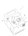
図1に、本実施形態における攪拌脱泡装置1を示している。この攪拌脱泡装置1は、複数の材料からなる被処理物を攪拌脱泡処理することができる装置である。尚、被処理物としては、例えば医療用材料や電子部品材料、液晶材料などの気泡を嫌う被攪拌材料の他、オフセット印刷機で使用するオフセットインキなどがある。
In FIG. 1, the
図1に示す攪拌脱泡装置1は、上端に開口2Kが形成された上方開放型のケーシング2と、そのケーシング2内に収容された本体部3とを備えている。尚、本体部3の上部に、後述する容器5の上部及び錘9を移動操作する回転ハンドルHを露出させるための2つの開口K1,K2が形成された板状のカバー部材Kを設けている。
A stirring and defoaming
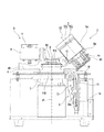
本体部3は、図2に示すように、公転軸芯X1回りに回転可能に構成されたテーブル4と、被処理物を収容可能に構成され、テーブル4に設置されて自転軸芯X2回りに自転可能になるとともにテーブル4の公転軸芯X1回りの回転によって公転可能になる容器5と、容器5をテーブル4上で自転させる自転用駆動機構6と、テーブル4を回転させることにより容器5を公転させる公転用回転駆動機構7とを備えている。尚、テーブル4上には、容器5の公転又は公転と自転の両方が行われることにより発生する遠心力によって自ずと移動して容器5の重心位置とのバランスを取ることができるバランス調整装置Bを備えている。このバランス調整装置Bは、特開2011−36805号公報に示したものと同一であるため、詳細な説明は省略する。
As shown in FIG. 2, the
テーブル4は、公転軸芯X1が設定される支軸8に連結された中央部4Aと、この中央部4Aの外側に位置し、中央部4Aよりも低くなった水平部4Bと、この水平部4Bの回転径方向外側に連続して形成され、回転径方向外側ほど上方に位置する傾斜面4cが形成された傾斜部4Cとを備えている。また、テーブル4は、前記傾斜部4Cの傾斜面4cに容器5を自転軸芯X2回りに回転自在に取り付けることができるように構成されている。具体的には、傾斜部4Cの傾斜面4cには、容器5が着脱自在に内装可能に構成され、下部に円周状の溝5Mが形成された回転部材5Aが設けられている。また、テーブル4は、公転軸芯X1を基準にして容器5と回転径方向でほぼ対称の配置となるように、バランス調整装置Bを構成する錘9が水平部4Bに設けられている。尚、錘9は、その上端に設けられた回転ハンドルHを操作することにより、テーブル4の回転径方向に沿って移動可能に構成されている。また、容器5の回転軸である自転軸芯X2は、その上端側ほどテーブル4の公転軸芯X1側に接近するように傾斜している。
The table 4 includes a
公転用回転駆動機構7は、公転用の電動モータ7と、該電動モータ7の駆動回転軸(図示せず)に外嵌されて一体回転するように構成され、公転軸芯X1が設定される支軸8とを備える。そして、この支軸8の上端に、テーブル4の中央部4Aが連結されている。
The revolving
容器5は、一端が開口された有底円筒状の本体部51aと、この本体部51aの開口を密閉することができる蓋部51bとを備えている。
The
自転用駆動機構6は、公転用の電動モータ7を駆動することにより支軸8と連れ回りするプーリ11と、プーリ11の回転力を前記回転部材5Aに伝動すべく、プーリ11と回転部材5Aの溝5Mとに渡って巻回された伝動ベルト12とを備えている。尚、前記プーリ11は、上下に溝11A,11Bが形成されており、上側の溝11Aに伝動ベルト12を介して前記回転部材5Aが連結され、下側の溝11Bに伝動機構13を介してパウダーブレーキ14が連結されている。
The
伝動機構13は、パウダーブレーキ14から水平方向へ突出する出力軸14Aに一体回転自在に取り付けられた負荷用プーリ15と、負荷用プーリ15及び前記プーリ11の下側の溝11Bを連動連結する伝動ベルト16とを備えている。前記パウダーブレーキ14に印加する電圧を増減させることによって、プーリ11に加えられる回転負荷を可変することでプーリ11の回転数を変化させることができるようになっている。ここでは、伝動機構13として、伝動ベルト16を用いたベルト式の伝動機構としているが、歯車(ギヤ)を用いた歯車(ギヤ)式の伝動機構であってもよい。
The
前記のように構成された攪拌脱泡装置は、制御装置U(図3参照)が備えられ、その制御装置Uによって制御されて動作するようになっている。ここで、その動作について説明する。まず、制御装置Uが、パウダーブレーキ14に加える電圧を0にして出力軸14Aをフリー(回転自在)にした状態で、公転用の電動モータ7を駆動すると、その回転が支軸8を介してテーブル4に伝動されてテーブル4が回転する一方で、負荷用プーリ15がフリー(回転自在)になっているため、負荷用プーリ15に伝動ベルト1を介して連結されているプーリ11が支軸8に対して連れ回りして伝動ベルト12はテーブル4の回転に対して相対的に回転駆動しない。その結果、容器5は、自転はせずに公転のみし、容器5内の被処理物に遠心力を作用させて被処理物に含まれている泡を被処理物から分離して脱泡することができる。
The stirring and defoaming device configured as described above is provided with a control device U (see FIG. 3), and is controlled and operated by the control device U. Here, the operation will be described. First, when the control device U drives the
前記とは逆に、制御装置Uが、パウダーブレーキ14に設定電圧を加えて、例えば出力軸14Aを非回転状態に固定した状態で、公転用の電動モータ7を駆動すると、その回転が支軸8を介してテーブル4に伝動されてテーブル4が回転する一方、負荷用プーリ15が非回転状態に固定されているため、該負荷用プーリ15に伝動ベルト16を介して連結されているプーリ11が支軸8の回転とは無関係に非回転状態になり、伝動ベルト12はテーブル4の回転に対して相対的に回転駆動して該回転駆動が回転部材5Aに伝動される。その結果、容器5は公転だけでなく自転もし、被処理物は、公転による遠心力で容器5の内側の壁面に押し付けられた状態で自転によって流動させられ、含まれている気泡を脱泡することができるとともに満遍なく攪拌することができる。尚、容器5は、テーブル4の回転方向とは逆方向に自転するとともにその最大自転速度がテーブル4の最大回転速度と同一速度になるように設定されているが、ギヤ比の設定変更や専用に設けられた自転モータを駆動制御することにより、公転速度と自転速度との比を1:1以外の比(例えば1:1.5など)にすることもできる。
Contrary to the above, when the control device U applies a set voltage to the
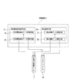
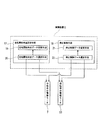
ここで、本実施形態における攪拌脱泡装置は、制御装置Uがパウダーブレーキ14に電圧を加えるタイミングを変更することによって、公転に対して自転を開始する時期を変更することができるように構成されており、その制御装置Uの構成について図3に基づいて説明する。
Here, the stirring and defoaming device in the present embodiment is configured such that the timing at which the control device U starts rotation can be changed by changing the timing at which the voltage is applied to the
制御装置Uは、容器5の自転を開始する時点を設定する自転開始時点設定手段17と、自転及び公転を行っている容器5の自転及び公転を停止させる停止制御手段18とを備えている。
The control device U includes a rotation start
自転開始時点設定手段17は、容器5の公転が開始されてから所定の公転速度になるまでの間の任意の時点で容器5の自転が開始されるように自転を開始する時点を設定する手段である。
The rotation start time setting means 17 is a means for setting the time point at which the rotation starts so that the rotation of the
また、自転開始時点設定手段17は、容器5の自転の開始時点に関する自転開始時点データであって、前記開始時点が異なる複数(ここでは2つ)の自転開始時点データを記憶するための自転開始時点データ記憶手段19と、自転開始時点データ記憶手段19に記憶されている2つの自転開始時点データの中から一つを選択して容器5の自転の開始時点として設定するための自転開始時点データ選択手段20とを備えている。
The rotation start time setting means 17 is rotation start time data for storing a plurality of rotation start time data (here, two) that are different from the rotation start time data regarding the rotation start time of the
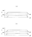
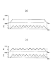
2つの自転開始時点データは、容器5が所定の公転速度v1になった時点を、自転開始時点とする第1自転開始データ(図4(a)参照)と、容器5の公転が開始された時点を自転開始時点とする第2自転開始データ(図4(b)参照)であり、自転開始時点データ選択手段20は、これら2つの開始データのうちのいずれか一方を選択可能(切替可能)に構成されている。
The two rotation start time data are the first rotation start data (see FIG. 4A) in which the time when the
停止制御手段18は、容器5が所定の公転速度及び所定の自転速度において運転している運転状態から、容器5の公転及び自転をそれぞれ減速させて停止させる手段であり、より具体的には、公転の減速が開始してから停止するまでの間で自転の減速を開始して停止するように、容器5の自転の減速開始時点及び停止時点を設定する手段である。
The stop control means 18 is a means for decelerating and stopping the revolution and rotation of the
また、停止制御手段18は、容器5の自転の減速が開始される時点に関する減速開始時点データ及び自転が停止される時点に関する停止時点データからなる停止制御データを複数(ここでは2つ)記憶するための停止制御データ記憶手段21と、停止制御データ記憶手段21に記憶されている2つの停止制御データの中から一つを選択して容器5の自転の減速開始時点及び停止時点として設定するための停止制御データ選択手段22とを備えている。
Further, the stop control means 18 stores a plurality (two in this case) of stop control data including deceleration start time data relating to the time when the rotation of the
ここで、2つの停止制御データは、減速開始時点データが、容器5が所定の公転速度から減速を開始した時点で自転の減速を開始するデータであり、停止時点データが、自転の減速が開始したら直ちに自転が停止するデータである、第1停止制御データ(図4(a)参照)と、減速開始時点データが、容器5が所定の公転速度から減速を開始した時点で自転の減速を開始するデータであり、停止時点データが、公転が停止する時点で自転を停止するデータである、第2停止制御データ(図4(b)参照)とである。停止制御データ選択手段22は、これら2つの停止制御データのうちのいずれか一方を選択可能(切替可能)に構成されている。
Here, the two stop control data are data for starting the deceleration when the
本実施形態における攪拌脱泡装置は、前記のように構成された制御装置Uにより、電動モータ7及びパウダーブレーキ14の駆動や停止を制御できるように構成されており、次に、かかる制御装置Uによる制御について説明する。
The stirring and defoaming device in the present embodiment is configured such that the driving and stopping of the
まず、作業者が第1自転開始データと第1停止制御データとを制御装置Uの操作パネル(図示せず)に備えている例えば選択手段(例えば、切替ボタンや切替スイッチ)を操作して選択する(切替える)場合について説明する。かかる選択をすると、制御装置Uは、第1自転開始データに基づいて、パウダーブレーキ14へ供給する電圧を0にした状態で公転用の電動モータ7の駆動を開始する信号を、パウダーブレーキ14の電圧供給部及び電動モータ7へそれぞれ出力する。そうすると、図4(a)に示すように、容器5の自転は開始せずに公転のみ開始する。そして、公転が加速して公転速度が所定速度v1に達すると、制御装置Uは、パウダーブレーキ14へ電圧を供給する信号を電圧供給部に出力する。そうすると、パウダーブレーキ14が作動して容器5の自転が開始する。また、公転速度が所定速度v1に達すると、制御装置Uは、公転の所定速度v1での定速回転(つまり、テーブル4の定速回転)を所定時間行わせる信号を出力する。尚、図4(a)に示す場合では、パウダーブレーキ14の電圧供給部へ出力した信号は、パウダーブレーキ14が、作動してから所定時間経過後に、出力軸14Aを非回転状態に固定する状態となるように制御する信号である。よって、出力軸14Aを非回転状態に固定した状態では、自転速度が公転速度v1と同じ速度v1となる。また、容器5の自転速度が公転速度と同一速度v1になると、制御装置Uは、その速度を維持するようにパウダーブレーキ14へ電圧を供給する信号を電圧供給部に出力する。
First, the operator selects the first rotation start data and the first stop control data by operating, for example, a selection means (for example, a switch button or a switch) provided on an operation panel (not shown) of the control device U. A case of performing (switching) will be described. When such a selection is made, the control device U sends a signal for starting driving the
そして、前記定速回転が所定時間行われると、容器5の公転及び自転を減速して停止させる停止制御に移行する。制御装置Uは、前記所定時間が経過すると、第1停止制御データに基づいて、電動モータ7の回転を減速する信号を電動モータ7に出力すると同時に、パウダーブレーキ14への電圧を直ちに0にする信号を電圧供給部に出力して、図4(a)に示すように、容器5の公転の減速を開始させつつ自転を直ちに停止させる。図4(a)では、容器5の公転の減速開始時点と自転の停止時点とが同一となっているが、実際には若干のタイムラグがあるため、実質的に同一とみなせる範囲において、自転の停止時点が公転の減速開始時点よりも多少時間経過した側(図4(a)では右側)にずれることもある。
And if the said constant speed rotation is performed for the predetermined time, it will transfer to the stop control which decelerates and stops the revolution and rotation of the
次に、攪拌脱泡作業において、作業者が第2自転開始データと第2停止制御データを制御装置Uの操作パネル(図示せず)に備えている選択手段(例えば、切替ボタンや切替スイッチ)を操作して選択する場合について説明する。かかる選択をすると、制御装置Uは、第2自転開始データに基づいて、パウダーブレーキ14へ電圧を供給した状態で公転用の電動モータ7の駆動を開始させる信号を、パウダーブレーキ14の電圧供給部及び電動モータ7へそれぞれ出力する。これにより図4(b)に示すように、容器5の公転が開始すると同時に、自転も開始する。尚、図4(b)に示す場合では、パウダーブレーキ14の電圧供給部へ出力した信号は、パウダーブレーキ14が、作動してから所定時間経過後に、出力軸14Aを非回転状態に固定する状態となるように制御する信号である。よって、出力軸14Aを非回転状態に固定した状態では、自転速度が公転速度v1と同じ速度v1となる。そして、容器5の公転速度及び自転速度が所定速度v1に達すると、制御装置Uは、公転及び自転の所定速度v1での定速回転を所定時間行わせる信号を、電動モータ7及び電圧供給部に出力する。
Next, in the agitation defoaming operation, the selection means (for example, a switch button or a switch) provided by the operator having the second rotation start data and the second stop control data on the operation panel (not shown) of the control device U. The case of selecting by operating will be described. When such a selection is made, the control device U outputs a signal for starting driving of the
そして、前記定速回転が所定時間行われると、容器5の公転及び自転を減速して停止させる停止制御に移行する。制御装置Uは、前記所定時間が経過すると、第2停止制御データに基づき、電動モータ7の回転を減速する信号を電動モータ7に出力すると同時に、パウダーブレーキ14への電圧を時間経過とともに徐々に低下させる信号を電圧供給部に出力して、図4(b)に示すように、容器5の公転の減速度と同じ減速度で容器5の自転を減速させて公転の停止時点と自転の停止時点とを一致させる。
And if the said constant speed rotation is performed for the predetermined time, it will transfer to the stop control which decelerates and stops the revolution and rotation of the
ここで、自転開始自転データの2つの自転開始データ(第1自転開始データ及び第2自転開始データ)の選択と、2つの停止制御データ(第1停止制御データ及び第2停止制御データ)の選択とは、被処理物を構成する材料の種類や性質に応じてなされる。 Here, selection of two rotation start data (first rotation start data and second rotation start data) of rotation start rotation data and selection of two stop control data (first stop control data and second stop control data) Is made according to the type and nature of the material constituting the workpiece.
つまり、被処理物が、比重差の小さい2種類の材料(具体的には、複数の液体材料、例えば比重の異なる2種類のエポキシ材料)からなる場合、第1自転開始データと第1停止制御データを選択することによって、図4(a)に示すように、第1自転開始データに基づいて、容器5が所定の公転速度になった時点で自転が開始されることから、処理の開始時において、被処理物には、容器5の公転による遠心力のみ作用して自転による攪拌力は作用しない。従って、比重差の小さい各液体材料が容器5内で大きく流動することがなく、所謂「泡噛み」の発生を防止することができる。しかも、停止制御においては、第1停止制御データに基づいて、公転と自転とを行っている容器5の公転を減速させる時点で自転を直ちに停止することによって、容器5の停止制御中においても、被処理物には、容器5の公転による遠心力のみ作用して自転による攪拌力は作用しない。よって、比重差の小さな各液体材料が容器5内で大きく流動するのを防止して所謂「泡噛み」を防止することができる。特に、所謂「泡噛み」は、容器5の公転を減速している途中の低速時に自転している場合に発生し易いため、公転の減速開始時点で自転を直ちに停止する場合のように、自転の停止時点を公転の停止時点よりも手前(時間的に早く)に設定することが好ましい。
That is, when the workpiece is made of two types of materials having a small specific gravity difference (specifically, a plurality of liquid materials, for example, two types of epoxy materials having different specific gravity), the first rotation start data and the first stop control. By selecting the data, as shown in FIG. 4A, the rotation is started when the
また、被処理物が、比重差の大きい2種類の材料(具体的には、粉材料と液体材料)からなる場合、第2自転開始データと第2停止制御データを選択する(切替える)ことによって、図4(b)に示すように、第2自転開始データに基づいて、容器5の公転と自転とが同時に開始されることから、公転による遠心力によって容器5の底面から上端面までの全域に亘って押し付けられている被処理物を、自転による攪拌力によって全体的に流動させることができる。よって、容器内の一箇所に比重が大きい材料(粉材料)が圧縮されてその全体又は一部が固まってしまうことを防止して十分に攪拌脱泡処理することができる。しかも、第2停止制御データに基づいて、公転と自転とを行っている容器5を、同時に減速させて、同時に停止させることができるから、停止制御中においても、容器内の一箇所に比重が大きい材料(粉材料)が圧縮されてその全体又は一部が固まってしまうことを防止することができる。尚、比重差の大きい2種類の材料の組み合わせとしては、比重1.5以上の材料、特にセラミック材料であるアルミナ粉と比重0.9〜1.1程度の液体材料であるシリコンとの組み合わせの他、電極用カーボン粉(粒径数μm〜数10μm)と溶剤との組み合わせなどが挙げられる。
Further, when the object to be processed is made of two kinds of materials having a large specific gravity difference (specifically, powder material and liquid material), by selecting (switching) the second rotation start data and the second stop control data. As shown in FIG. 4B, since the revolution and rotation of the
尚、本発明は、前記実施形態に限定されるものではなく、本発明の要旨を逸脱しない範囲で種々の変更が可能である。 In addition, this invention is not limited to the said embodiment, A various change is possible in the range which does not deviate from the summary of this invention.
前記実施形態では、2つの自転開始データと2つの停止制御データとから、図4(a),(b)に示す2つのパターンの制御を切替可能なようにしたが、2つの自転開始データと2つの停止制御データとの組み合わせを変更して、4つのパターンの制御を行うように構成してもよい。つまり、図4(a),(b)の2つのパターンと、図4(a)の自転開始データ(第1自転開始データ)と図4(b)の停止制御データ(第2停止制御データ)とを組み合わせた1つのパターンと、図4(b)の自転開始データ(第2自転開始データ)と図4(a)の停止制御データ(第1停止制御データ)とを組み合わせた1つのパターンとからなる4つのパターンであってもよい。 In the embodiment, the two patterns shown in FIGS. 4A and 4B can be switched from the two rotation start data and the two stop control data, but the two rotation start data and The combination with the two stop control data may be changed so that four patterns are controlled. That is, the two patterns of FIGS. 4A and 4B, the rotation start data (first rotation start data) of FIG. 4A and the stop control data (second stop control data) of FIG. 4B. And a single pattern combining the rotation start data (second rotation start data) in FIG. 4B and the stop control data (first stop control data) in FIG. There may be four patterns.
また、前記実施形態では、2つの自転開始データを自転開始時点データ記憶手段19に記憶させ、2つの停止制御データを停止制御データ記憶手段21に記憶させたが、3つ以上の自転開始データを自転開始時点データ記憶手段19に記憶させ、同じく3つ以上の停止制御データを停止制御データ記憶手段21に記憶させて、それらの中から1つの自転開始データと1つの停止制御データとを選択する構成であってもよい。
In the embodiment, two rotation start data are stored in the rotation start time
ここで、自転開始データ及び停止制御データの他の例を図5(a),(b)に示している。図5(a)では、自転開始データは、公転速度が所定の速度になるように加速している途中の速度(公転速度が所定の公転速度v1のほぼ半分)になった時点から自転を開始するデータであり、公転と自転とは、ほぼ同じ加速度である。停止制御データは、公転の減速が開始した時点から自転の減速を開始し、公転が停止する時間よりも短い時間(公転の停止時間のほぼ半分の時間)で自転が停止するデータであり、公転の減速度よりも自転の減速度の方が大きくなっている。また、図5(b)では、自転開始データは、公転と自転とは同時に開始し、公転が所定の公転速度に達する前に(公転が所定の公転速度のほぼ半分に達した時点で)自転速度が所定の自転速度に達するデータであり、公転の加速度は自転の加速度より小さくなっている。停止制御データは、公転の減速が開始し後に(公転の速度がほぼ半分に減速された時点で)自転の減速を開始し、公転と自転とを同じ停止時点とするデータであり、自転の減速度が公転の減速度よりも大きくなっている。図5(b)に示すように、自転の加速度が公転の加速度よりも大きくし、自転の減速度が公転の減速度よりも大きくするためには、図7に示すように、公転用の電動モータ7と自転用の電動モータ23とを用いることになる。また、実施形態で示した自転開始時点設定手段17は、自転の開始時点を容器5の公転が開始されてから所定の公転速度になるまでの間の任意の時点で該容器5の自転が開始されるように該自転の開始時点を設定する手段であったが、容器5の公転が開始されてから所定の公転速度になった後の任意の時点で容器5の自転が開始されるように、該自転の開始時点を設定してもよい。要するに、容器5の公転が開始された後であれば、どのような時点に該容器5の自転の開始時点を設定してもよい。
Here, other examples of the rotation start data and the stop control data are shown in FIGS. In FIG. 5 (a), the rotation start data starts rotation from the time when the rotation speed reaches a predetermined speed (the rotation speed is approximately half of the predetermined rotation speed v1). The revolution and rotation are almost the same acceleration. The stop control data is data that starts the deceleration of the rotation from the point when the deceleration of the revolution starts and stops the rotation in a time shorter than the time when the revolution stops (approximately half the stop time of the revolution). The deceleration of rotation is greater than the deceleration of. In FIG. 5B, the rotation start data indicates that rotation and rotation start at the same time, and before the revolution reaches a predetermined revolution speed (when the revolution reaches almost half of the predetermined revolution speed). It is data for which the speed reaches a predetermined rotation speed, and the acceleration of revolution is smaller than the acceleration of rotation. Stop control data is data that starts rotation deceleration after the revolution deceleration starts (when the revolution speed is reduced by almost half) and sets the revolution and rotation to the same stop point. The speed is larger than the deceleration of revolution. As shown in FIG. 5B, in order to make the rotation acceleration larger than the revolution acceleration and the rotation deceleration larger than the revolution deceleration, as shown in FIG. The
尚、自転開始データと停止制御データとを別々のデータとして記憶させる場合に限らず、1つの自転開始データと1つの停止制御データとを組み合わせた自転制御データを複数組記憶させ、記憶された複数の自転制御データの中から1つの自転制御データを選択する構成であってもよい。 Note that the rotation start data and the stop control data are not limited to be stored as separate data, and a plurality of rotation control data obtained by combining one rotation start data and one stop control data are stored and stored. One rotation control data may be selected from among the rotation control data.
また、停止制御データを同一の1つのデータとし、自転開始データのみ複数の異なるデータから構成し、それら複数の自転開始データの中から1つの自転開始データを選択する構成であってもよい。 Alternatively, the stop control data may be the same single data, only the rotation start data may be composed of a plurality of different data, and one rotation start data may be selected from the plurality of rotation start data.
また、前記実施形態では、自転速度及び公転速度が所定速度になると、定速制御を行うようにしたが、図6(a)に示すように、自転速度を可変にしてもよい。図6(a)のグラフでは、自転速度の波形が、速度v1からv2の間の速度範囲内で上下方向に一定周期で波打つ(正弦波状に波打つ)ように変化している。尚、自転速度が変化する速度範囲は、一定幅の範囲である場合に限らず、時間経過とともに徐々に増大又は減少するあるいは増大と減少を繰り返すように変化する場合であってもよい。また、自転が正転と逆転とを繰り返す構成であってもよい。この場合の正転と逆転との時間の比率は、どのように設定することも可能である。尚、図6(a)において、公転と自転とが同時に実行され、停止時点も同一にしているが、これらに限定されない。 In the above embodiment, the constant speed control is performed when the rotation speed and the revolution speed reach predetermined speeds. However, as shown in FIG. 6A, the rotation speed may be variable. In the graph of FIG. 6A, the waveform of the rotation speed changes so as to wave in the up and down direction at a constant period (wave in a sine wave shape) within the speed range between the speeds v1 and v2. The speed range in which the rotation speed changes is not limited to a certain range, and may be a case where the speed range gradually increases or decreases with time and changes so as to repeat increase and decrease. Moreover, the structure which autorotation repeats normal rotation and reverse rotation may be sufficient. In this case, the ratio of time between forward rotation and reverse rotation can be set in any manner. In FIG. 6 (a), revolution and rotation are executed simultaneously and the stopping time is also the same, but it is not limited to these.
また、定速制御の代わりに、自転だけでなく公転も速度変化させる制御をすることも可能である。図6(b)では、公転速度の波形も自転速度の波形と同様に速度v1からv2の間の速度範囲内で上下方向に一定周期で波打つ(正弦波状に波打つ)ように変化している。尚、公転速度が変化する速度範囲についても、自転速度の速度範囲と同様に、時間経過とともに徐々に増大減少するあるいは増大と減少を繰り返すように変化する場合であってもよい。また、自転と同様に、公転が正転と逆転とを繰り返す構成であってもよい。特に、公転の回転方向に対して自転が正転方向又は逆転方向に回転する構成が好ましい。この場合の正転と逆転との時間の比率は、どのように設定することも可能である。尚、図6(b)において、公転と自転とが同時に実行され、停止時点も同一にしているが、これらに限定されない。 Further, instead of the constant speed control, it is possible to perform not only the rotation but also the revolution to change the speed. In FIG. 6B, the waveform of the revolution speed also changes so as to wave in the up and down direction at a constant period (waves in a sine wave) within the speed range between the speeds v1 and v2, similarly to the waveform of the rotation speed. Note that the speed range in which the revolution speed changes may also be a case where the speed range gradually increases or decreases with time, or changes such that the increase and decrease are repeated, similar to the speed range of the rotation speed. Moreover, the structure which revolution repeats forward rotation and reverse rotation similarly to autorotation may be sufficient. In particular, a configuration in which the rotation rotates in the normal rotation direction or the reverse rotation direction with respect to the rotation direction of revolution is preferable. In this case, the ratio of time between forward rotation and reverse rotation can be set in any manner. In addition, in FIG.6 (b), revolution and autorotation are performed simultaneously, and the stop time is also made the same, However, It is not limited to these.
尚、上記のように公転又は自転を正転及び逆転させるためには、図7に示すように、公転用の電動モータ7の他に、自転用の電動モータ23を備えさせて、それら2つの電動モータ7,23を駆動制御することになる。
In addition, in order to perform normal rotation and reverse rotation of the revolution or rotation as described above, in addition to the
また、前記実施形態では、公転用の電動モータ7とパウダーブレーキ14とで容器5の自転を行わせるとともにパウダーブレーキ14への電圧の供給タイミングを変更することによって、少なくとも公転の開始時点に対する容器5の自転の開始時点を制御するようにしたが、図7に示すように、公転用の電動モータ7の他に、自転用の電動モータ23を備えさせて、それら2つの電動モータ7,23を駆動制御することによって、公転の開始時点に対する容器5の自転の開始時点を制御する構成であってもよい。要するに、容器5の公転と自転とを別々に制御できる構成であれば、公転に対する自転の開始時点を制御することができる。但し、電動モータ7とパウダーブレーキ14とを用いることによって、装置の構成を簡略化して小型化を図ることができ、一方、2つの電動モータ7,23を用いることによって、公転速度よりも自転速度を速くすることができるだけでなく、容器5の公転方向と自転方向とを自由に変更することができる利点がある。
Further, in the above-described embodiment, the
また、前記実施形態では、1つの容器5をテーブル4上に設けた構成にしたが、複数の容器5をテーブル4上に設けた構成であってもよい。
Moreover, in the said embodiment, although the structure which provided the one
1…攪拌脱泡装置、2…ケーシング、2K…開口、3…本体部、4…テーブル、4A…中央部、4B…水平部、4C…傾斜部、4c…傾斜面、5…容器、5A…回転部材、5M…溝、6…自転用駆動機構、7…公転用回転駆動機構(公転用の電動モータ)、8…支軸、9…錘、11…プーリ、11A,11B…溝、12…伝動ベルト、13…伝動機構、14…パウダーブレーキ、14A…出力軸、15…負荷用プーリ、16…伝動ベルト、17…自転開始時点設定手段、18…停止制御手段、19…自転開始時点データ記憶手段、20…自転開始時点データ選択手段、21…停止制御データ記憶手段、22…停止制御データ選択手段、23…電動モータ、51a…本体部、51b…蓋部、B…バランス調整装置、H…回転ハンドル、K…カバー部材、K1,K2…開口、U…制御装置、X1…公転軸芯、X2…自転軸芯
DESCRIPTION OF
Claims (5)
前記容器の公転が開始された後の任意の時点で該容器の自転が開始されるように該自転の開始時点を設定する自転開始時点設定手段を備えたことを特徴とする攪拌脱泡装置。 A container for containing an object to be treated, the container being a stirring and defoaming device configured to perform both revolution and rotation;
An agitation / deaeration apparatus comprising a rotation start time setting means for setting the rotation start time so that the rotation of the container starts at an arbitrary time after the revolution of the container is started.
Priority Applications (1)
| Application Number | Priority Date | Filing Date | Title |
|---|---|---|---|
| JP2011058754A JP2012192352A (en) | 2011-03-17 | 2011-03-17 | Agitation defoaming device |
Applications Claiming Priority (1)
| Application Number | Priority Date | Filing Date | Title |
|---|---|---|---|
| JP2011058754A JP2012192352A (en) | 2011-03-17 | 2011-03-17 | Agitation defoaming device |
Publications (1)
| Publication Number | Publication Date |
|---|---|
| JP2012192352A true JP2012192352A (en) | 2012-10-11 |
Family
ID=47084795
Family Applications (1)
| Application Number | Title | Priority Date | Filing Date |
|---|---|---|---|
| JP2011058754A Pending JP2012192352A (en) | 2011-03-17 | 2011-03-17 | Agitation defoaming device |
Country Status (1)
| Country | Link |
|---|---|
| JP (1) | JP2012192352A (en) |
Cited By (1)
| Publication number | Priority date | Publication date | Assignee | Title |
|---|---|---|---|---|
| WO2017068995A1 (en) * | 2015-10-23 | 2017-04-27 | 株式会社写真化学 | Stirring/degassing method and stirring/degassing device |
Citations (2)
| Publication number | Priority date | Publication date | Assignee | Title |
|---|---|---|---|---|
| JPH07289873A (en) * | 1994-04-27 | 1995-11-07 | Shashin Kagaku:Kk | Agitation and defoaming device for solvent or the like |
| JPH1043567A (en) * | 1996-07-31 | 1998-02-17 | Shinkii:Kk | Kneading device |
-
2011
- 2011-03-17 JP JP2011058754A patent/JP2012192352A/en active Pending
Patent Citations (2)
| Publication number | Priority date | Publication date | Assignee | Title |
|---|---|---|---|---|
| JPH07289873A (en) * | 1994-04-27 | 1995-11-07 | Shashin Kagaku:Kk | Agitation and defoaming device for solvent or the like |
| JPH1043567A (en) * | 1996-07-31 | 1998-02-17 | Shinkii:Kk | Kneading device |
Cited By (5)
| Publication number | Priority date | Publication date | Assignee | Title |
|---|---|---|---|---|
| WO2017068995A1 (en) * | 2015-10-23 | 2017-04-27 | 株式会社写真化学 | Stirring/degassing method and stirring/degassing device |
| JP2017080645A (en) * | 2015-10-23 | 2017-05-18 | 株式会社写真化学 | Agitation defoaming method and agitation defoaming apparatus |
| CN108290087A (en) * | 2015-10-23 | 2018-07-17 | 株式会社写真化学 | A kind of stirring defoaming method and churning deaerator |
| US10722818B2 (en) | 2015-10-23 | 2020-07-28 | Shashin Kagaku Co., Ltd. | Agitation/defoaming method and agitation/defoaming device |
| CN108290087B (en) * | 2015-10-23 | 2021-05-28 | 株式会社写真化学 | Stirring defoaming method and stirring defoaming device |
Similar Documents
| Publication | Publication Date | Title |
|---|---|---|
| JP4740749B2 (en) | mixer | |
| EP2210655A1 (en) | Churning deaerator | |
| JP2006305512A (en) | Stirring and defoaming method and stirring and defoaming apparatus | |
| JP2015016403A (en) | Agitation defoaming device | |
| JP2011050814A (en) | Agitation defoaming apparatus | |
| JP5138432B2 (en) | Material filling equipment | |
| JPH07289873A (en) | Agitation and defoaming device for solvent or the like | |
| JP4188411B1 (en) | Method for stopping stirring deaerator and stirring deaerator | |
| JP4068981B2 (en) | Stirring deaerator | |
| JP5506039B2 (en) | Container used for stirring deaerator and stirring deaerator | |
| JP6705968B2 (en) | Revolution device | |
| JP2007144352A (en) | Agitation degassing method and its agitation degassing apparatus | |
| JP2012192352A (en) | Agitation defoaming device | |
| JP2008178850A (en) | Agitating and defoaming apparatus for material to be agitated | |
| JP2009291700A (en) | Agitation defoaming apparatus | |
| JP2008062209A (en) | Rotation transmission apparatus | |
| JP2006263697A (en) | Method and apparatus for agitating/defoaming material to be agitated by using ultrasonic wave | |
| JP5154522B2 (en) | Material filling apparatus and material filling method | |
| JP5357809B2 (en) | Induction current generator, rotation sensor, and stirring deaerator | |
| JP2011092912A (en) | Stirring defoaming method and stirring defoaming apparatus | |
| JP5775714B2 (en) | Stirring deaerator | |
| JP2009082895A (en) | Kneading and defoaming apparatus and kneading and defoaming method for material to be kneaded and defoamed | |
| JP6718725B2 (en) | Three-dimensional rotation/revolution type stirring device | |
| JP2011092912A5 (en) | Stirring deaerator | |
| JP2012136284A (en) | Plunger inserter, adapter for the same, and method for manufacturing syringe unit |
Legal Events
| Date | Code | Title | Description |
|---|---|---|---|
| RD04 | Notification of resignation of power of attorney |
Free format text: JAPANESE INTERMEDIATE CODE: A7424 Effective date: 20130801 |
|
| A621 | Written request for application examination |
Free format text: JAPANESE INTERMEDIATE CODE: A621 Effective date: 20140212 |
|
| A977 | Report on retrieval |
Free format text: JAPANESE INTERMEDIATE CODE: A971007 Effective date: 20140724 |
|
| A131 | Notification of reasons for refusal |
Free format text: JAPANESE INTERMEDIATE CODE: A131 Effective date: 20140801 |
|
| A521 | Request for written amendment filed |
Free format text: JAPANESE INTERMEDIATE CODE: A523 Effective date: 20140929 |
|
| A02 | Decision of refusal |
Free format text: JAPANESE INTERMEDIATE CODE: A02 Effective date: 20150306 |