JP2012191315A - Image reader, image forming device and program - Google Patents
Image reader, image forming device and program Download PDFInfo
- Publication number
- JP2012191315A JP2012191315A JP2011051488A JP2011051488A JP2012191315A JP 2012191315 A JP2012191315 A JP 2012191315A JP 2011051488 A JP2011051488 A JP 2011051488A JP 2011051488 A JP2011051488 A JP 2011051488A JP 2012191315 A JP2012191315 A JP 2012191315A
- Authority
- JP
- Japan
- Prior art keywords
- image
- area
- document
- reading
- unit
- Prior art date
- Legal status (The legal status is an assumption and is not a legal conclusion. Google has not performed a legal analysis and makes no representation as to the accuracy of the status listed.)
- Granted
Links
Images


Abstract
Description
本発明は、画像読取装置、画像形成装置およびプログラムに関する。 The present invention relates to an image reading apparatus, an image forming apparatus, and a program.
特許文献1には、パンチ穴パターンを予め記憶しておき、このパンチ穴パターンとの照合を行うことによりパンチ穴を識別し、パンチ穴の画像データを消去、中抜きするような画像形成装置が開示されている。
特許文献2には、実際に原稿画像を読み取る前にプリスキャンを行ってパンチ穴を検出するようにした画像読取装置が開示されている。 Patent Document 2 discloses an image reading apparatus that detects a punch hole by performing pre-scanning before actually reading a document image.
特許文献3には、原稿画像の予め設定された探索範囲を探索することによりパンチ穴候補を抽出し、抽出されたパンチ穴候補からパンチ穴を特定して除去するようにした画像処理装置が開示されている。 Patent Document 3 discloses an image processing apparatus in which punch hole candidates are extracted by searching a preset search range of a document image, and punch holes are identified and removed from the extracted punch hole candidates. Has been.
本発明の目的は、パンチ穴等のように原稿全体の領域中において原稿が存在しない領域を、処理時間を長くすることなく検出することが可能な画像読取装置、画像形成装置およびプログラムを提供することである。 An object of the present invention is to provide an image reading apparatus, an image forming apparatus, and a program capable of detecting an area where no original exists in an entire area of the original such as a punch hole without increasing the processing time. That is.
[画像処理装置]
請求項1に係る本発明は、光源からの光を原稿に照射して、その反射光を読み取ることにより原稿の画像を画像信号として読み取る画像読取手段と、
前記画像読取手段により読み取られた原稿の画像信号を、予め設定された範囲で表現された画像データに変換する変換手段と、
前記画像読取手段により原稿として使用される印刷用紙の白地領域を読み取った画像信号が、画像データで表現可能な範囲の最大値とならないように前記変換手段を調整する調整手段と、
前記画像読取手段により読み取られる原稿の裏面に配置され、前記画像読取手段により読み取られた画像信号のうちの少なくとも1色が、画像データで表現可能な範囲の最大値に飽和するような部材により構成された反射部材と、
前記変換手段により変換された画像データにおいて表現可能な範囲の最大値となっている領域を検出することにより、原稿全体の領域中における原稿が存在しない領域である背景領域を検出する検出手段とを備えた画像読取装置である。
[Image processing device]
According to a first aspect of the present invention, there is provided an image reading unit that reads an image of an original as an image signal by irradiating the original with light from a light source and reading the reflected light.
Conversion means for converting an image signal of a document read by the image reading means into image data expressed in a preset range;
An adjusting means for adjusting the converting means so that an image signal obtained by reading a white area of a printing paper used as a document by the image reading means does not become a maximum value in a range that can be expressed by image data;
A member arranged on the back side of the document read by the image reading unit and configured to saturate at least one color of the image signals read by the image reading unit to a maximum value that can be expressed by image data. A reflected member,
Detecting means for detecting a background area, which is an area in which no document exists in the entire document area, by detecting an area having a maximum value that can be expressed in the image data converted by the converting means; An image reading apparatus provided.
請求項2に係る本発明は、前記検出手段により検出された背景領域の周辺の、濃度値が予め設定された値より大きい影領域の画像を、予め設定された白地データに変換することにより背景領域周辺の影領域の画像を消去する消去手段をさらに備えた請求項1記載の画像読取装置である。
According to a second aspect of the present invention, an image of a shadow area around the background area detected by the detecting unit and having a density value larger than a preset value is converted into preset white background data. The image reading apparatus according to
請求項3に係る本発明は、前記検出手段により検出された背景領域の画素から予め設定された画素数の範囲内にある画像を影領域の画像として判定する判定手段をさらに備えた請求項2記載の画像読取装置である。 The present invention according to claim 3 further comprises determination means for determining an image within a preset number of pixels from the pixels in the background area detected by the detection means as an image in the shadow area. It is an image reading apparatus of description.
請求項4に係る本発明は、前記検出手段により検出された背景領域の画素から予め設定された画素数以内で連続して隣接している画像を影領域の画像として判定する判定手段をさらに備えた請求項2記載の画像読取装置である。 According to a fourth aspect of the present invention, the image processing apparatus further includes a determination unit that determines, as a shadow region image, images that are continuously adjacent to each other within a preset number of pixels from the background region pixels detected by the detection unit. The image reading apparatus according to claim 2.
[画像形成装置]
請求項5に係る本発明は、光源からの光を原稿に照射して、その反射光を読み取ることにより原稿の画像を画像信号として読み取る画像読取手段と、
前記画像読取手段により読み取られた原稿の画像信号を、予め設定された範囲で表現された画像データに変換する変換手段と、
前記画像読取手段により原稿として使用される印刷用紙の白地領域を読み取った画像信号が、画像データで表現可能な範囲の最大値とならないように前記変換手段を調整する調整手段と、
前記画像読取手段により読み取られる原稿の裏面に配置され、前記画像読取手段により読み取られた画像信号のうちの少なくとも1色が、画像データで表現可能な範囲の最大値に飽和するような部材により構成された反射部材と、
前記変換手段により変換された画像データにおいて表現可能な範囲の最大値となっている領域を検出することにより、原稿全体の領域中における原稿が存在しない領域である背景領域を検出する検出手段と、
前記検出手段により検出された背景領域の周辺の、濃度値が予め設定された値より大きい影領域の画像を、予め設定された白地データに変換することにより背景領域周辺の影領域の画像を消去する消去手段と、
前記消去手段により背景領域周辺の影領域の画像が消去された後の原稿画像を出力する画像出力手段をを備えた画像形成装置である。
[Image forming apparatus]
According to a fifth aspect of the present invention, there is provided image reading means for reading an image of a document as an image signal by irradiating the document with light from a light source and reading the reflected light.
Conversion means for converting an image signal of a document read by the image reading means into image data expressed in a preset range;
An adjusting means for adjusting the converting means so that an image signal obtained by reading a white area of a printing paper used as a document by the image reading means does not become a maximum value in a range that can be expressed by image data;
A member arranged on the back side of the document read by the image reading unit and configured to saturate at least one color of the image signals read by the image reading unit to a maximum value that can be expressed by image data. A reflected member,
Detecting means for detecting a background area that is an area in which no document exists in the entire document area by detecting an area that is the maximum value of the range that can be expressed in the image data converted by the converting means;
The shadow area image around the background area detected by the detection means is erased by converting the shadow area image whose density value is larger than a preset value into preset white background data. Erasing means to perform,
The image forming apparatus includes an image output unit that outputs a document image after the image in the shadow area around the background area is erased by the erasing unit.
[プログラム]
請求項6に係る本発明は、光源からの光を原稿に照射して、その反射光を読み取ることにより原稿の画像を画像信号として読み取るステップと、
読み取られた原稿の画像信号を、予め設定された範囲で表現された画像データに変換するステップと、
変換された画像データにおいて表現可能な範囲の最大値となっている領域を検出することにより、原稿全体の領域中における原稿が存在しない領域である背景領域を検出するステップとをコンピュータに実行させるためのプログラムである。
[program]
The present invention according to claim 6 is a step of reading an image of an original as an image signal by irradiating the original with light from a light source and reading the reflected light;
Converting the image signal of the read document into image data expressed in a preset range;
And detecting a background area that is an area in which no document exists in the entire document area by detecting an area that is the maximum value that can be expressed in the converted image data. It is a program.
請求項1に係る本発明によれば、パンチ穴等のように原稿全体の領域中において原稿が存在しない領域を、本構成を有しない場合と比較して、処理時間を長くすることなく検出することができる画像処理装置を提供することができる。 According to the first aspect of the present invention, an area where the original does not exist, such as a punch hole, is detected without increasing the processing time compared to a case where the original configuration does not exist. It is possible to provide an image processing apparatus that can
請求項2に係る本発明によれば、請求項1に係る本発明により得られる効果に加えて、パンチ穴等の背景領域に存在する影領域の画像を消去することができる画像処理装置を提供することができる。 According to the second aspect of the present invention, in addition to the effect obtained by the first aspect of the present invention, an image processing apparatus capable of erasing an image of a shadow region existing in a background region such as a punch hole is provided. can do.
請求項3に係る本発明によれば、請求項2に係る本発明により得られる効果に加えて、パンチ穴等の背景領域の予め設定された画素数の範囲内に存在する影領域の画像を消去することができる画像処理装置を提供することができる。 According to the third aspect of the present invention, in addition to the effect obtained by the second aspect of the present invention, an image of a shadow region existing within a preset number of pixels of a background region such as a punch hole is obtained. An image processing apparatus that can be erased can be provided.
請求項4に係る本発明によれば、請求項2に係る本発明により得られる効果に加えて、パンチ穴等の背景領域から予め設定された画素数以内で連続して隣接している画像を消去することができる画像処理装置を提供することができる。 According to the present invention of claim 4, in addition to the effect obtained by the present invention of claim 2, images that are continuously adjacent to each other within a preset number of pixels from a background region such as a punch hole are obtained. An image processing apparatus that can be erased can be provided.
請求項5に係る本発明によれば、パンチ穴等のように原稿全体の領域中において原稿が存在しない領域を、本構成を有しない場合と比較して、処理時間を長くすることなく検出することができる画像形成装置を提供することができる。 According to the fifth aspect of the present invention, an area where the original does not exist, such as a punch hole, is detected without increasing the processing time compared to the case where the present configuration is not provided. It is possible to provide an image forming apparatus capable of performing the above.
請求項6に係る本発明によれば、パンチ穴等のように原稿全体の領域中において原稿が存在しない領域を、本構成を有しない場合と比較して、処理時間を長くすることなく検出することができるプログラムを提供することができる。 According to the sixth aspect of the present invention, an area where the original is not present in the entire area of the original such as a punch hole is detected without increasing the processing time compared to the case where the present configuration is not provided. A program can be provided.
次に、本発明の実施の形態について図面を参照して詳細に説明する。
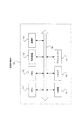
図1は本発明の一実施形態の画像形成システムの構成を示す図である。
Next, embodiments of the present invention will be described in detail with reference to the drawings.
FIG. 1 is a diagram showing a configuration of an image forming system according to an embodiment of the present invention.
本発明の一実施形態の画像形成システムは、図1に示されるように、ネットワーク30により相互に接続された画像形成装置10、および端末装置20により構成される。端末装置20は、印刷データを生成して、ネットワーク30経由にて生成した印刷データを画像形成装置10に対して送信する。画像形成装置10は、端末装置20から送信された印刷データを受け付けて、印刷データに応じた画像を用紙上に出力する。なお、画像形成装置10は、印刷(プリント)機能、スキャン機能、複写(コピー)機能、ファクシミリ機能等の複数の機能を有するいわゆる複合機と呼ばれる装置である。
As shown in FIG. 1, the image forming system according to an embodiment of the present invention includes an
次に、本実施形態の画像形成システムにおける画像形成装置10のハードウェア構成を図2に示す。
Next, FIG. 2 shows a hardware configuration of the
画像形成装置10は、図2に示されるように、CPU11、メモリ12、ハードディスクドライブ(HDD)等の記憶装置13、ネットワーク30を介して外部の装置等との間でデータの送信及び受信を行う通信インタフェース(IF)14、タッチパネル又は液晶ディスプレイ並びにキーボードを含むユーザインタフェース(UI)装置15、スキャナ16、プリントエンジン17を有する。これらの構成要素は、制御バス18を介して互いに接続されている。
As shown in FIG. 2, the
CPU11は、メモリ12または記憶装置13に格納された制御プログラムに基づいて所定の処理を実行して、画像形成装置10の動作を制御する。
The
なお、本実施形態では、CPU11は、メモリ12または記憶装置13内に格納された制御プログラムを読み出して実行するものとして説明したが、当該プログラムをCD−ROM等の記憶媒体に格納してCPU11に提供することも可能である。
In the present embodiment, the
上記の制御プログラムが実行されることにより実現される画像形成装置10における画像読取装置周辺の機能構成を図3に示す。
FIG. 3 shows a functional configuration around the image reading apparatus in the
本実施形態の画像形成装置10における画像読取装置は、図3に示されるように、蓋部40および本体部50とから構成されている。そして、この蓋部40にはいわゆるDADF(Duplex Auto Document Feeder)と呼ばれる自動両面原稿送り装置が設けられており、原稿の自動送りが可能になっている。
As shown in FIG. 3, the image reading apparatus in the
また、蓋部40は、原稿トレイ26と、原稿トレイ26上に載置された原稿60の待機位置に設けられた原稿分離ロール21と、原稿を搬送する原稿搬送ロール22と、排出ロール24と、反射部材23とを有している。これらの原稿分離ロール21、原稿搬送ロール22、排出ロール24等により、複数ページの原稿を順次所定の原稿読み取り位置まで搬送される。
The
本体部50は、プラテンガラス25と、原稿搬送ロール22等の原稿搬送手段により原稿読み取り位置まで搬送された原稿の画像をページ毎に読み取るための画像読取部70と、信号変換部41と、画像処理部42と、ダイナミックレンジ調整部43とを有している。
The
画像読取部70は、原稿を照射する光源であるキセノンランプ31と、反射ミラー32、33と、結像レンズ34と、CCD等の光電変換素子35とから構成されている。そして、この画像読取部70は、キセノンランプ31からの光を原稿に照射して、その反射光を読み取ることにより原稿の画像を画像信号として読み取る。
The image reading unit 70 includes a
画像読取部70は、図示しないキャリッジに設けられていて、副走査方向に移動可能となっている。そのため、プラテンガラス25上に載置された原稿の画像を読み取る場合には、画像読取部70は、副走査方向に移動しながら原稿の読み取りを行うことができる。また、原稿トレイ26上に載置された原稿の画像を読み取る場合には、画像読取部70は、図3に示されるように、原稿搬送ロール22等により原稿が順次搬送されてくる原稿読み取り位置まで移動することにより、原稿トレイ26から搬送されてきた原稿の画像を順次読み取ることができるような構成となっている。
The image reading unit 70 is provided on a carriage (not shown) and is movable in the sub-scanning direction. Therefore, when reading an image of a document placed on the
信号変換部41は、画像読取部70により読み取られた原稿の画像信号を、予め設定された範囲で表現された画像データに変換する。具体的には、信号変換部41は、画像読取部70からのアナログ信号を、8ビットで表された0〜255の範囲の画像データに変換する。ここで、画像データが0の場合には、輝度が最も暗いことを示していて、画像データが255の場合には、輝度が最も明るいことを示している。
The
ダイナミックレンジ調整部43は、画像読取部70により原稿として使用される印刷用紙の白地領域を読み取った画像信号が、画像データで表現可能な範囲(0〜255)の最大値とならないように信号変換部41のダイナミックレンジを調整する。
The dynamic range adjustment unit 43 performs signal conversion so that the image signal obtained by reading the white background area of the printing paper used as a document by the image reading unit 70 does not become the maximum value in the range (0 to 255) that can be expressed by the image data. The dynamic range of the
そして、蓋部40内には、搬送されてくる原稿の主走査方向の背面を覆うようにして反射部材23が設けられている。この反射部材23は、画像読取部70により読み取られる原稿の裏面に配置され、画像読取部70により読み取られた画像信号のうちの少なくとも1色が、画像データで表現可能な範囲の最大値に飽和するような部材により構成されている。
In the
一般的な白色の印刷用紙の白色部分を撮像したデータをL*a*b*表色系で表現した場合の明度指数L*は、L*<97の範囲となる。そのため、反射部材23として、例えばL*>97となるような反射率の高い部材を用いることにより、印刷用紙の白地部分を読み取った画像信号では飽和しないが、反射部材23を読み取った画像信号が飽和するような設定が可能となる。
The brightness index L * in the case where data obtained by imaging the white portion of a general white printing paper is expressed in the L * a * b * color system is in the range of L * <97. For this reason, by using a highly reflective member such as L *> 97 as the reflecting
また、反射部材23は、キセノンランプ31からの照明光が、反射ミラー33、結像レンズ34を経由して光電変換素子35に至る経路に正反射されるような角度で設置されている。
The
ここで、信号変換部41における変換処理における、画像読取部70からの画像信号の信号レベルと画像データの変換値との関係の一例を図4に示す。
Here, FIG. 4 shows an example of the relationship between the signal level of the image signal from the image reading unit 70 and the conversion value of the image data in the conversion process in the
この図4に示したグラフでは、画像読取部70により印刷用紙の白地部分を読み取った画像信号の信号レベルはα未満となっている。そのため、印刷用紙の白地部分を読み取った信号レベルを画像データに変換した場合の変換値は255未満となる。しかし、反射部材23を読み取った画像信号の信号レベルはαよりも大きくなっている。そのため、反射部材32からの反射光が光電変換素子35に入力されると、信号変換部41では、最大値である255を画像データとして出力することとなる。
In the graph shown in FIG. 4, the signal level of the image signal obtained by reading the white background portion of the printing paper by the image reading unit 70 is less than α. Therefore, the conversion value when the signal level obtained by reading the white background portion of the printing paper is converted into image data is less than 255. However, the signal level of the image signal read from the reflecting
画像処理部42は、信号変換部41によりデジタル信号に変換された画像データに対して各種の画像処理を行う機能を有する。具体的には、画像処理部42は、図5に示されるように、背景領域検出部51と、影領域検出部52と、消去領域判定部53と、影領域消去処理部54とを備えている。
The
背景領域検出部51は、信号変換部41により変換された画像データにおいて表現可能な範囲の最大値、つまり255となっている領域を検出することにより、原稿全体の領域中における原稿が存在しない領域(欠損している領域)である背景領域を検出する。
The background
具体的には、背景領域検出部51は、信号変換部41からの画像データの各画素の値と、予め設定されている背景判定閾値(例えば254)とをそれぞれ比較して、画像データの画素の値が背景判定閾値よりも大きい場合には、その画素は背景領域に含まれる画素であると判定する。この場合、例えば、背景領域検出部51は、背景判定信号として、背景領域に含まれる画素に対しては“1”を出力し、背景領域に含まれない画素に対しては“0”を出力する。
Specifically, the background
影領域検出部52は、信号変換部41からの画像データのうち、濃度値が予め設定された値より大きい影領域の検出を行う。具体的には、影領域検出部52は、信号変換部41からの画像データの各画素の値と、予め設定されている影判定閾値(例えば128)とをそれぞれ比較して、画像データの画素の値が影判定閾値未満の場合には、その画素は影領域に含まれる画素であると判定する。この場合、例えば、影領域検出部52は、影領域判定信号として、影領域に含まれる画素に対しては“1”を出力し、影領域に含まれない画素に対しては“0”を出力する。
The shadow
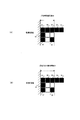
消去領域判定部53は、影領域検出部52により検出された影領域(影判定信号=1の領域)のうち、背景領域検出部51により検出された背景領域の画素(背景判定信号=1)から予め設定された画素数(消去範囲画素数M)の範囲内にある画像を消去対象の影領域の画像として判定する。
The erasure
例えば、消去範囲画素数M=3画素とした場合、消去領域判定部53は、図6(A)に示すように、背景領域と判定された画像から3画素の範囲内にある影領域の画素91〜93、96、97、98を消去対象の画素として判定する。
For example, when the erasure range pixel number M is 3 pixels, the erasure
なお、消去領域判定部53は、影領域検出部52により検出された背景領域の画素から予め設定された画素数(連続消去制限画素数N)以内で連続して隣接している画像を消去対象の影領域の画像として判定するようにしてもよい。
It should be noted that the erasure
この場合には、例えば、連続消去制限画素数N=3画素とした場合、消去領域判定部53は、図6(B)に示すように、背景領域と判定された画像から3画素以内で連続して隣接している影領域の画素91〜93、96、97を消去対象の画素として判定する。ここでは、影領域の画素98は、背景領域から連続して隣接していないため消去対象には含まれない。
In this case, for example, when the continuous erasure limit pixel number N is set to 3 pixels, the erasure
さらに、消去領域判定部53は、背景領域と隣接しているか否かの判定に隣接ギャップ画素数を見込んだ判定を行うようにしてもよい。具体的には、消去領域判定部53は、背景領域から予め設定された隣接ギャップ画素数以内離れた画素は背景領域と隣接しているものとして判定を行うようにしてもよい。また、消去領域判定部53は、影領域を膨張処理させて消去対象の領域を判定するようにしてもよいし、影領域の膨張処理と収縮処理を行うことによりノイズ画像を除去するようにしてもよい。
Further, the erasure
ここで膨張処理とは、例えば、影領域画像の周囲を1画素分増やす処理をいい、収縮処理とは、影領域画像の周囲を1画素分減らす処理を言う。そして、影領域に対して膨張処理を行った後に収縮処理を行うことにより、影領域の小さな窪みや孔を埋めることができ、逆に影領域に対して収縮処理を行った後に膨張処理を行うと小さな突起や点状のノイズを取り除くことができる。 Here, the expansion process refers to, for example, a process that increases the periphery of the shadow area image by one pixel, and the contraction process refers to a process that decreases the periphery of the shadow area image by one pixel. Then, by performing the contraction process after performing the expansion process on the shadow area, it is possible to fill a small depression or hole in the shadow area, and conversely, after performing the contraction process on the shadow area, the expansion process is performed. And small protrusions and point-like noise can be removed.
影領域消去処理部54は、消去領域判定部53により消去対象の影領域の画像として判定された画像を、予め設定された白地データに変換することにより背景領域周辺の影領域の画像を消去する。つまり、影領域消去処理部54は、背景領域検出部51により検出された背景領域の周辺の、濃度値が予め設定された値より大きい影領域の画像を、予め設定された白地データに変換することにより背景領域周辺の影領域の画像を消去することとなる。
The shadow area
なお、影領域消去処理部54は、影領域の画像を予め設定された白地データに変換するのではなく、用紙の地色を検出する手段により取得された原稿地色データに変換するようにしてもよい。
The shadow area
また、本実施形態の画像形成装置10には、画像出力部80が備えられている。この画像出力部80は、影領域消去処理部54により背景領域周辺の影領域の画像が消去された後の原稿画像を印刷用紙上に出力する。
Further, the
次に、本実施形態の画像読取装置の動作を図面を参照して詳細に説明する。 Next, the operation of the image reading apparatus of this embodiment will be described in detail with reference to the drawings.
本実施形態の画像読取装置における影領域の消去処理の流れを図7のフローチャートに示す。以下の説明では、図8に示すような原稿を読み取って影領域を消去する場合を用いて説明する。この図8に示した原稿には、原稿の隅が斜めに欠損した用紙端71と、2つのパンチ穴72が存在するものとして説明する。
The flow of the shadow area erasing process in the image reading apparatus of the present embodiment is shown in the flowchart of FIG. In the following description, description will be made using a case where a shadow area is erased by reading a document as shown in FIG. The document shown in FIG. 8 will be described on the assumption that a
先ず、背景領域検出部51は、画像読取部70により読み取られ信号変換部41により変換された画像データから、画素値が255になっている飽和データ領域を背景領域、つまり原稿が欠損している領域として検出する(ステップS101)。
First, the background
ここで、図8に示した原稿における用紙端71周辺の拡大図を図9(A)に示し、パンチ穴72周辺の拡大図を図9(B)に示す。
Here, FIG. 9A shows an enlarged view around the
図9(A)に示すように、用紙端71周辺では、背景領域82における画像データの画素値は255となっていて、影領域81における画像データの画素値は10となっている。そして、用紙の白地部分の画像データは、230、231等のように255よりも小さい値となっていることが分かる。そのため、背景領域検出部51は、画素値が255の領域を探すことにより背景領域82を検出することができる。
As shown in FIG. 9A, around the
また、図9(B)に示すように、パンチ穴72周辺では、背景領域84における画像データの画素値は255となっていて、影領域83における画像データの画素値は10となっている。そして、用紙の白地部分の画像データは、231〜233等のように255よりも小さい値となっていることが分かる。そのため、背景領域検出部51は、画素値が255の領域を探すことにより背景領域84を検出することができる。
Further, as shown in FIG. 9B, around the
次に、影領域検出部52は、信号変換部41からの画像データから、画素値が予め設定されている影判定閾値未満となっている領域を、濃度値が一定値以上の影領域として検出する(ステップS102)。
Next, the shadow
例えば、図9(A)に示したような用紙端71周辺では、画素値が10となっている影領域81が影領域検出部52により影領域として検出される。また、図9(B)に示したようなパンチ穴72周辺では、画素値が10となっている影領域83が影領域検出部52により影領域として検出される。
For example, around the
次に、消去領域判定部53では、影領域検出部52により検出された影領域のうち、背景領域検出部51により検出された背景領域の画素から予め設定された画素数の範囲内にある画像を消去対象の影領域の画像として判定する(ステップS103)。
Next, in the erasure
なお、図8に示した原稿画像を読み取った場合の、信号変換部41からの画像データの画素値とデータ頻度との関係の一例を図10に示す。図10に示されるように、原稿の文字画像領域の画像データと原稿の用紙白地の画像データとは影判定閾値(128)を境界にして明確に判定可能であることが分かる。また、原稿の用紙白地の画像データと背景画像の画像データも、背景判定閾値を境界にして明確に判定可能であることが分かる。しかし、原稿の文字画像領域の画像データと用紙端71、パンチ穴72等の影領域の画像データとは一部が交錯しており完全に分離することは不可能であることが分かる。
FIG. 10 shows an example of the relationship between the pixel value of the image data from the
そのため、影領域検出部52では、図9に示したような影領域81、83だけでなく、原稿の文字画像領域の画像データの一部も影領域の画像であると判定される可能性がある。そのため、消去領域判定部53では、背景領域の画素周辺に存在する影領域の画素のみを消去対象として判定する。
Therefore, the shadow
例えば、図9(A)に示したような用紙端71周辺では、画素値が10となっている影領域81が消去領域判定部53により消去対象の影領域として検出される。また、図9(B)に示したようなパンチ穴72周辺では、画素値が10となっている影領域83が消去領域判定部53により消去対象の影領域として検出される。
For example, in the vicinity of the
そして、最後に影領域消去処理部54は、消去領域判定部53により消去対象の影領域の画像として判定された画像を、予め設定された白地データに変換することにより背景領域周辺の影領域の画像を消去する(ステップS104)。この影領域消去処理部54による影領域の消去処理により、図8に示した画像から用紙端71に起因する影領域や、パンチ穴72に起因する影領域が消去され、図11に示すような画像が得られる。
Finally, the shadow area
[変形例]
上記実施形態では、DADF等の原稿搬送手段により原稿を順次搬送して原稿画像を読み取る場合を用いて説明したが、本発明はこれに限定されるものではなく、プラテンガラス25上に載置された原稿を読み取る場合でも同様に本発明を適用することができるものである。
[Modification]
In the above embodiment, the case where the original is sequentially conveyed by the original conveying means such as DADF and the original image is read has been described. However, the present invention is not limited to this and is placed on the
例えば、プラテンガラス25上に載置された原稿の読み取りを行う場合に、蓋部40に設けられた押さえ板に反射部材23と同様の反射率を有する部材を用いることにより、プラテンガラス25上に載置された原稿におけるパンチ穴等の欠損領域を検出することが可能となる。
For example, when a document placed on the
また、同様の構成を用いれば、プラテンガラス25上に載置された原稿におけるパンチ穴等の欠損領域を検出するだけでなく、プラテンガラス25上に載置された原稿の原稿サイズを検出することも可能となる。
In addition, if a similar configuration is used, not only a defect area such as a punch hole in a document placed on the
10 画像形成装置
11 CPU
12 メモリ
13 記憶装置
14 通信インタフェース(IF)
15 ユーザインタフェース(UI)装置
16 スキャナ
17 プリントエンジン
18 制御バス
20 端末装置
21 原稿分離ロール
22 原稿搬送ロール
23 反射部材
24 排出ロール
25 プラテンガラス
26 原稿トレイ
30 ネットワーク
31 キセノンランプ
32、33 反射ミラー
34 結像レンズ
35 光電変換素子
40 蓋部
41 信号変換部
42 画像処理部
43 ダイナミックレンジ調整部
50 本体部
51 背景領域検出部
52 影領域検出部
53 消去領域判定部
54 影領域消去処理部
60 原稿
70 画像読取部
71 用紙端
72 パンチ穴
80 画像出力部
81 影領域
82 背景領域
83 影領域
84 背景領域
10
12
DESCRIPTION OF
Claims (6)
前記画像読取手段により読み取られた原稿の画像信号を、予め設定された範囲で表現された画像データに変換する変換手段と、
前記画像読取手段により原稿として使用される印刷用紙の白地領域を読み取った画像信号が、画像データで表現可能な範囲の最大値とならないように前記変換手段を調整する調整手段と、
前記画像読取手段により読み取られる原稿の裏面に配置され、前記画像読取手段により読み取られた画像信号のうちの少なくとも1色が、画像データで表現可能な範囲の最大値に飽和するような部材により構成された反射部材と、
前記変換手段により変換された画像データにおいて表現可能な範囲の最大値となっている領域を検出することにより、原稿全体の領域中における原稿が存在しない領域である背景領域を検出する検出手段と、
を備えた画像読取装置。 Image reading means for reading the image of the document as an image signal by irradiating the document with light from a light source and reading the reflected light;
Conversion means for converting an image signal of a document read by the image reading means into image data expressed in a preset range;
An adjusting means for adjusting the converting means so that an image signal obtained by reading a white area of a printing paper used as a document by the image reading means does not become a maximum value in a range that can be expressed by image data;
A member arranged on the back side of the document read by the image reading unit and configured to saturate at least one color of the image signals read by the image reading unit to a maximum value that can be expressed by image data. A reflected member,
Detecting means for detecting a background area that is an area in which no document exists in the entire document area by detecting an area that is the maximum value of the range that can be expressed in the image data converted by the converting means;
An image reading apparatus comprising:
前記画像読取手段により読み取られた原稿の画像信号を、予め設定された範囲で表現された画像データに変換する変換手段と、
前記画像読取手段により原稿として使用される印刷用紙の白地領域を読み取った画像信号が、画像データで表現可能な範囲の最大値とならないように前記変換手段を調整する調整手段と、
前記画像読取手段により読み取られる原稿の裏面に配置され、前記画像読取手段により読み取られた画像信号のうちの少なくとも1色が、画像データで表現可能な範囲の最大値に飽和するような部材により構成された反射部材と、
前記変換手段により変換された画像データにおいて表現可能な範囲の最大値となっている領域を検出することにより、原稿全体の領域中における原稿が存在しない領域である背景領域を検出する検出手段と、
前記検出手段により検出された背景領域の周辺の、濃度値が予め設定された値より大きい影領域の画像を、予め設定された白地データに変換することにより背景領域周辺の影領域の画像を消去する消去手段と、
前記消去手段により背景領域周辺の影領域の画像が消去された後の原稿画像を出力する画像出力手段と
を備えた画像形成装置。 Image reading means for reading the image of the document as an image signal by irradiating the document with light from a light source and reading the reflected light;
Conversion means for converting an image signal of a document read by the image reading means into image data expressed in a preset range;
An adjusting means for adjusting the converting means so that an image signal obtained by reading a white area of a printing paper used as a document by the image reading means does not become a maximum value in a range that can be expressed by image data;
A member arranged on the back side of the document read by the image reading unit and configured to saturate at least one color of the image signals read by the image reading unit to a maximum value that can be expressed by image data. A reflected member,
Detecting means for detecting a background area that is an area in which no document exists in the entire document area by detecting an area that is the maximum value of the range that can be expressed in the image data converted by the converting means;
The shadow area image around the background area detected by the detection means is erased by converting the shadow area image whose density value is larger than a preset value into preset white background data. Erasing means to perform,
An image forming apparatus comprising: an image output unit that outputs a document image after an image in a shadow region around a background region is erased by the erasing unit.
読み取られた原稿の画像信号を、予め設定された範囲で表現された画像データに変換するステップと、
変換された画像データにおいて表現可能な範囲の最大値となっている領域を検出することにより、原稿全体の領域中における原稿が存在しない領域である背景領域を検出するステップとをコンピュータに実行させるためのプログラム。 Irradiating the document with light from a light source and reading the reflected light to read the image of the document as an image signal;
Converting the image signal of the read document into image data expressed in a preset range;
And detecting a background area that is an area in which no document exists in the entire document area by detecting an area that is the maximum value that can be expressed in the converted image data. Program.
Priority Applications (1)
| Application Number | Priority Date | Filing Date | Title |
|---|---|---|---|
| JP2011051488A JP5850295B2 (en) | 2011-03-09 | 2011-03-09 | Image reading apparatus, image forming apparatus, and program |
Applications Claiming Priority (1)
| Application Number | Priority Date | Filing Date | Title |
|---|---|---|---|
| JP2011051488A JP5850295B2 (en) | 2011-03-09 | 2011-03-09 | Image reading apparatus, image forming apparatus, and program |
Publications (2)
| Publication Number | Publication Date |
|---|---|
| JP2012191315A true JP2012191315A (en) | 2012-10-04 |
| JP5850295B2 JP5850295B2 (en) | 2016-02-03 |
Family
ID=47084028
Family Applications (1)
| Application Number | Title | Priority Date | Filing Date |
|---|---|---|---|
| JP2011051488A Active JP5850295B2 (en) | 2011-03-09 | 2011-03-09 | Image reading apparatus, image forming apparatus, and program |
Country Status (1)
| Country | Link |
|---|---|
| JP (1) | JP5850295B2 (en) |
Cited By (7)
| Publication number | Priority date | Publication date | Assignee | Title |
|---|---|---|---|---|
| JP2015012432A (en) * | 2013-06-28 | 2015-01-19 | 京セラドキュメントソリューションズ株式会社 | Image reader, image forming apparatus, and image processing method |
| JP2015012347A (en) * | 2013-06-27 | 2015-01-19 | 富士ゼロックス株式会社 | Document reading device and image forming apparatus |
| JP2016195339A (en) * | 2015-03-31 | 2016-11-17 | ブラザー工業株式会社 | Image processing program, image processing device and image processing method |
| JP2016195336A (en) * | 2015-03-31 | 2016-11-17 | ブラザー工業株式会社 | Image processing program, image processing device and image processing method |
| JP2016194824A (en) * | 2015-03-31 | 2016-11-17 | ブラザー工業株式会社 | Image processing program, image processor, and image processing method |
| JP2016195337A (en) * | 2015-03-31 | 2016-11-17 | ブラザー工業株式会社 | Image processing program, image processing device and image processing method |
| JP2016195338A (en) * | 2015-03-31 | 2016-11-17 | ブラザー工業株式会社 | Image processing program, image processing device and image processing method |
Citations (4)
| Publication number | Priority date | Publication date | Assignee | Title |
|---|---|---|---|---|
| US4538185A (en) * | 1983-09-30 | 1985-08-27 | Xerox Corporation | Platen cover for document boundary detection in raster scanners |
| JPH02264562A (en) * | 1989-04-05 | 1990-10-29 | Canon Inc | Image reader |
| JP2007228032A (en) * | 2006-02-21 | 2007-09-06 | Matsushita Electric Ind Co Ltd | Image reader and image forming apparatus equipped with it |
| JP2008042841A (en) * | 2006-08-10 | 2008-02-21 | Canon Inc | Document reading apparatus |
-
2011
- 2011-03-09 JP JP2011051488A patent/JP5850295B2/en active Active
Patent Citations (4)
| Publication number | Priority date | Publication date | Assignee | Title |
|---|---|---|---|---|
| US4538185A (en) * | 1983-09-30 | 1985-08-27 | Xerox Corporation | Platen cover for document boundary detection in raster scanners |
| JPH02264562A (en) * | 1989-04-05 | 1990-10-29 | Canon Inc | Image reader |
| JP2007228032A (en) * | 2006-02-21 | 2007-09-06 | Matsushita Electric Ind Co Ltd | Image reader and image forming apparatus equipped with it |
| JP2008042841A (en) * | 2006-08-10 | 2008-02-21 | Canon Inc | Document reading apparatus |
Cited By (8)
| Publication number | Priority date | Publication date | Assignee | Title |
|---|---|---|---|---|
| JP2015012347A (en) * | 2013-06-27 | 2015-01-19 | 富士ゼロックス株式会社 | Document reading device and image forming apparatus |
| JP2015012432A (en) * | 2013-06-28 | 2015-01-19 | 京セラドキュメントソリューションズ株式会社 | Image reader, image forming apparatus, and image processing method |
| US9197762B2 (en) | 2013-06-28 | 2015-11-24 | Kyocera Document Solutions Inc. | Image reading device, forming apparatus, and processing method detecting and removing perforations to correctly identify blank documents |
| JP2016195339A (en) * | 2015-03-31 | 2016-11-17 | ブラザー工業株式会社 | Image processing program, image processing device and image processing method |
| JP2016195336A (en) * | 2015-03-31 | 2016-11-17 | ブラザー工業株式会社 | Image processing program, image processing device and image processing method |
| JP2016194824A (en) * | 2015-03-31 | 2016-11-17 | ブラザー工業株式会社 | Image processing program, image processor, and image processing method |
| JP2016195337A (en) * | 2015-03-31 | 2016-11-17 | ブラザー工業株式会社 | Image processing program, image processing device and image processing method |
| JP2016195338A (en) * | 2015-03-31 | 2016-11-17 | ブラザー工業株式会社 | Image processing program, image processing device and image processing method |
Also Published As
| Publication number | Publication date |
|---|---|
| JP5850295B2 (en) | 2016-02-03 |
Similar Documents
| Publication | Publication Date | Title |
|---|---|---|
| JP5850295B2 (en) | Image reading apparatus, image forming apparatus, and program | |
| JP6797716B2 (en) | Image processing device and image processing method | |
| JP6338469B2 (en) | Image processing apparatus and image processing method | |
| US9571693B2 (en) | Image processing apparatus, image processing method, and program | |
| JP2010284802A (en) | Image forming apparatus and image forming system | |
| JP5183587B2 (en) | Image processing apparatus, image processing method, and program for executing image processing method | |
| JP4379488B2 (en) | Image reading device | |
| JP6838348B2 (en) | Image reader and image reading method | |
| JP2015198327A (en) | Image reading device, image reading method, and computer program | |
| US20140063561A1 (en) | Image processing apparatus, image forming apparatus, and image processing method | |
| JP7391653B2 (en) | Image processing device, image processing method, and program | |
| JP2009303112A (en) | Image forming apparatus, image forming system and program | |
| JP2018022950A (en) | Image reading device and image reading method | |
| JP2018085650A (en) | Reading device and control method | |
| JP5317115B2 (en) | Image reading device | |
| JP5306077B2 (en) | Image reading device | |
| JP5474222B2 (en) | Image processing apparatus, image processing method, and program | |
| JP2003198838A (en) | Image processing system and image processing method | |
| KR20190090252A (en) | Image scanning apparatus for detecting shadow of paper and method for scanning thereof | |
| JP2017199976A (en) | Image processing apparatus, image processing method and program | |
| JP5021524B2 (en) | Image forming apparatus | |
| JP2018088611A (en) | Image reading device, image reading method, and image reading program | |
| JP6081874B2 (en) | Image reading device | |
| JP2009200599A (en) | Image processing apparatus and image forming apparatus | |
| JP2012142722A (en) | Reading apparatus, control method, and program |
Legal Events
| Date | Code | Title | Description |
|---|---|---|---|
| A621 | Written request for application examination |
Free format text: JAPANESE INTERMEDIATE CODE: A621 Effective date: 20140218 |
|
| A977 | Report on retrieval |
Free format text: JAPANESE INTERMEDIATE CODE: A971007 Effective date: 20141224 |
|
| A131 | Notification of reasons for refusal |
Free format text: JAPANESE INTERMEDIATE CODE: A131 Effective date: 20150114 |
|
| A521 | Written amendment |
Free format text: JAPANESE INTERMEDIATE CODE: A523 Effective date: 20150312 |
|
| A131 | Notification of reasons for refusal |
Free format text: JAPANESE INTERMEDIATE CODE: A131 Effective date: 20150821 |
|
| A521 | Written amendment |
Free format text: JAPANESE INTERMEDIATE CODE: A523 Effective date: 20151020 |
|
| TRDD | Decision of grant or rejection written | ||
| A01 | Written decision to grant a patent or to grant a registration (utility model) |
Free format text: JAPANESE INTERMEDIATE CODE: A01 Effective date: 20151106 |
|
| A61 | First payment of annual fees (during grant procedure) |
Free format text: JAPANESE INTERMEDIATE CODE: A61 Effective date: 20151119 |
|
| R150 | Certificate of patent or registration of utility model |
Ref document number: 5850295 Country of ref document: JP Free format text: JAPANESE INTERMEDIATE CODE: R150 |
|
| S533 | Written request for registration of change of name |
Free format text: JAPANESE INTERMEDIATE CODE: R313533 |
|
| R350 | Written notification of registration of transfer |
Free format text: JAPANESE INTERMEDIATE CODE: R350 |