JP6338469B2 - Image processing apparatus and image processing method - Google Patents
Image processing apparatus and image processing method Download PDFInfo
- Publication number
- JP6338469B2 JP6338469B2 JP2014128621A JP2014128621A JP6338469B2 JP 6338469 B2 JP6338469 B2 JP 6338469B2 JP 2014128621 A JP2014128621 A JP 2014128621A JP 2014128621 A JP2014128621 A JP 2014128621A JP 6338469 B2 JP6338469 B2 JP 6338469B2
- Authority
- JP
- Japan
- Prior art keywords
- reading
- image
- document
- show
- correction
- Prior art date
- Legal status (The legal status is an assumption and is not a legal conclusion. Google has not performed a legal analysis and makes no representation as to the accuracy of the status listed.)
- Active
Links
- 238000003672 processing method Methods 0.000 title claims description 3
- 238000000034 method Methods 0.000 claims description 58
- 238000009499 grossing Methods 0.000 claims description 34
- 238000000605 extraction Methods 0.000 claims 4
- 230000002093 peripheral effect Effects 0.000 claims 1
- 238000005070 sampling Methods 0.000 description 34
- 239000006185 dispersion Substances 0.000 description 28
- 239000000872 buffer Substances 0.000 description 24
- 238000010586 diagram Methods 0.000 description 12
- 230000003287 optical effect Effects 0.000 description 12
- 238000007781 pre-processing Methods 0.000 description 9
- 241000533901 Narcissus papyraceus Species 0.000 description 7
- 238000005286 illumination Methods 0.000 description 5
- 238000003705 background correction Methods 0.000 description 3
- 239000003086 colorant Substances 0.000 description 3
- 238000001514 detection method Methods 0.000 description 3
- 239000011521 glass Substances 0.000 description 3
- 230000005540 biological transmission Effects 0.000 description 2
- 238000006243 chemical reaction Methods 0.000 description 2
- 238000003708 edge detection Methods 0.000 description 2
- 238000001914 filtration Methods 0.000 description 2
- 230000006870 function Effects 0.000 description 2
- 230000001360 synchronised effect Effects 0.000 description 2
- 230000015572 biosynthetic process Effects 0.000 description 1
- 230000001627 detrimental effect Effects 0.000 description 1
- 238000003384 imaging method Methods 0.000 description 1
- 239000000203 mixture Substances 0.000 description 1
- 230000000717 retained effect Effects 0.000 description 1
- 238000000926 separation method Methods 0.000 description 1
- 239000007787 solid Substances 0.000 description 1
- 238000002834 transmittance Methods 0.000 description 1
Images


Classifications
-
- H—ELECTRICITY
- H04—ELECTRIC COMMUNICATION TECHNIQUE
- H04N—PICTORIAL COMMUNICATION, e.g. TELEVISION
- H04N1/00—Scanning, transmission or reproduction of documents or the like, e.g. facsimile transmission; Details thereof
- H04N1/40—Picture signal circuits
- H04N1/409—Edge or detail enhancement; Noise or error suppression
- H04N1/4095—Correction of errors due to scanning a two-sided document, i.e. show-through correction
-
- G—PHYSICS
- G06—COMPUTING; CALCULATING OR COUNTING
- G06K—GRAPHICAL DATA READING; PRESENTATION OF DATA; RECORD CARRIERS; HANDLING RECORD CARRIERS
- G06K15/00—Arrangements for producing a permanent visual presentation of the output data, e.g. computer output printers
- G06K15/02—Arrangements for producing a permanent visual presentation of the output data, e.g. computer output printers using printers
- G06K15/18—Conditioning data for presenting it to the physical printing elements
- G06K15/1867—Post-processing of the composed and rasterized print image
- G06K15/1869—Depleting the print image
-
- G—PHYSICS
- G06—COMPUTING; CALCULATING OR COUNTING
- G06K—GRAPHICAL DATA READING; PRESENTATION OF DATA; RECORD CARRIERS; HANDLING RECORD CARRIERS
- G06K15/00—Arrangements for producing a permanent visual presentation of the output data, e.g. computer output printers
- G06K15/02—Arrangements for producing a permanent visual presentation of the output data, e.g. computer output printers using printers
- G06K15/18—Conditioning data for presenting it to the physical printing elements
- G06K15/1867—Post-processing of the composed and rasterized print image
- G06K15/1872—Image enhancement
- G06K15/1881—Halftoning
-
- H—ELECTRICITY
- H04—ELECTRIC COMMUNICATION TECHNIQUE
- H04N—PICTORIAL COMMUNICATION, e.g. TELEVISION
- H04N1/00—Scanning, transmission or reproduction of documents or the like, e.g. facsimile transmission; Details thereof
- H04N1/40—Picture signal circuits
- H04N1/405—Halftoning, i.e. converting the picture signal of a continuous-tone original into a corresponding signal showing only two levels
Landscapes
- Engineering & Computer Science (AREA)
- Multimedia (AREA)
- Signal Processing (AREA)
- General Engineering & Computer Science (AREA)
- Physics & Mathematics (AREA)
- General Physics & Mathematics (AREA)
- Theoretical Computer Science (AREA)
- Image Processing (AREA)
- Facsimile Image Signal Circuits (AREA)
Description
本発明は、画像を補正する画像処理装置及び画像処理方法に関するものである。 The present invention relates to an image processing apparatus and an image processing method for correcting an image.
複写機、複合機などにおいて、それらに実装されている画像読取装置(スキャナ)を用いて原稿を読み取った場合に「裏写り」という問題が生じることがある。「裏写り」は原稿の一方の面(おもて面)を画像読取装置で読み取った場合に、当該原稿のもう一方の面(うら面)の画像が読み取り画像に写り込んでしまうものである。よって、画像読取装置で読み取る原稿の両面(おもて面およびうら面)に何らかの画像が印刷されていた場合に主に発生するものである。この裏写りは、裏面に高濃度の画像が存在する場合に発生しやすい。また、読み取り時の光源の光量や、読み取り原稿の媒体(用紙など)の厚み(光の透過具合)の程度に起因して発生する。この裏写りが発生してしまうと、読み取り画像内の画像が見づらくなり、すなわち、画像の品質が劣化する。 In a copying machine, a multifunction machine, and the like, when an original is read using an image reading device (scanner) mounted thereon, a problem of “show-through” may occur. “Back-through” means that when one side (front side) of a document is read by an image reading device, the image on the other side (back side) of the document is reflected in the read image. . Therefore, this occurs mainly when some image is printed on both sides (the front side and the back side) of the document read by the image reading apparatus. This show-through tends to occur when a high-density image exists on the back surface. Further, it occurs due to the amount of light of the light source at the time of reading and the thickness of the medium (paper or the like) of the read document (light transmission degree). If this show-through occurs, it becomes difficult to see the image in the read image, that is, the quality of the image deteriorates.
そこで、読み取り画像における裏写りを低減する技術として、画像の濃度を全体的に下げる(いわゆる「下地飛ばし機能」を強く働かせる)処理が用いられることがある。ただし、この場合、裏写りだけでなく原稿のおもて面に存在した画像の濃度も下がってしまうことになる。そのため、濃度の薄い画像は消失してしまう恐れがある。 Therefore, as a technique for reducing the show-through in the read image, there is a case where processing for lowering the overall image density (making the so-called “background removal function” work strongly) is used. However, in this case, not only the show-through but also the density of the image existing on the front surface of the document is lowered. For this reason, an image with a low density may be lost.
そこで、例えば特許文献1では、注目画素を含む一定範囲の分散値を求め、当該分散値が予め定められた基準値以下のときに裏写り除去処理を実行する技術が提案されている。これは画像の低濃度部分が網点として表現されていることに着目した処理であって、網点として表現された領域の画像データの分散値が高くなる特徴を利用したものである。裏写りの成分はおもて面からみると網点として表現されにくく、分散値が低くなる。よって分散値が基準値以下か否かに基づいて、画像が裏写り成分であるかおもて面の低濃度部分かを切り分け、裏写り成分のみに裏写り除去処理を実行している。
Therefore, for example,
しかしながら、特許文献1に開示された技術では、原稿の網点周期と原稿の読み取り光学解像度の関係によっては、同一網点領域内で裏写り除去がされる領域と裏写り除去がされない領域が生じるという課題が生じる。
However, in the technique disclosed in
原稿の読み取り光学解像度が決まると、原稿内の画素を読み取るサンプリング周波数が決まる。このとき原稿内の網点周波数が前記サンプリング周波数の1/2付近(ナイキスト周波数付近)であると、読み取った原稿データ内において正しく網点が解像されない領域が発生する。すると原稿の網点領域内において網点が解像されていない領域と解像されている領域が混在し、分散値が低い領域と分散値が高い領域に分離され、一つの網点領域内で裏写り除去がされる領域と裏写り除去がされない領域とが生じるという課題が発生する。 When the reading optical resolution of the document is determined, the sampling frequency for reading the pixels in the document is determined. At this time, if the halftone dot frequency in the original is about ½ of the sampling frequency (near the Nyquist frequency), an area in which the halftone dot is not correctly resolved occurs in the read original data. Then, in the halftone dot area of the original, the area where the halftone dots are not resolved and the area where the halftone dots are resolved are mixed, and the area is divided into a low dispersion value area and a high dispersion value area. There arises a problem that a region where the show-through removal is performed and a region where the show-through removal is not performed are generated.
上述した課題を解決するために、本発明の画像処理装置は、特定の読取解像度で原稿を読み取り可能な読取手段と、前記読取手段によって前記原稿を読み取って得られた画像データから、前記特定の読取解像度に基づいて決まるナイキスト周波数付近の周波数に対応する周期を有する網点領域を抽出する抽出手段と、前記抽出手段によって抽出された網点領域に対して、平滑化処理を行う平滑化手段と、前記平滑化手段によって平滑化処理された領域に対して、前記原稿の裏写りを除去するために明るさ補正を行う補正手段とを有する。 To solve the problems described above, the image processing apparatus of the present invention, a reading unit capable of read-document at a specific reading resolution, the image data obtained by reading the document by the reading means, the specific Extracting means for extracting a halftone dot region having a period corresponding to a frequency in the vicinity of the Nyquist frequency determined based on the reading resolution, and a smoothing means for performing a smoothing process on the halftone dot region extracted by the extracting means And correction means for performing brightness correction on the area smoothed by the smoothing means in order to remove show-through of the original .
本発明によれば、原稿内の網点周波数が、原稿を読み取った読取手段の読み取りサンプリング周波数の1/2付近であったとしても、裏写りがおこっている原稿を読み取って得られた画像データに対して、高精度に裏写り除去を行うことができる。 According to the present invention, even if the halftone dot frequency in the original is about ½ of the reading sampling frequency of the reading means that has read the original, the image data obtained by reading the original showing the show-through On the other hand, show-through removal can be performed with high accuracy.
以下に、図面を参照して、この発明の好適な実施の形態を詳しく説明する。なお、以下の実施の形態はあくまで例示であり、本発明の範囲を限定する趣旨のものではない。 Hereinafter, preferred embodiments of the present invention will be described in detail with reference to the drawings. The following embodiments are merely examples, and are not intended to limit the scope of the present invention.
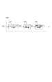
本発明に係る実施例1の画像処理装置として、複写機1000を例に挙げて以下に説明する。 The image processing apparatus according to the first embodiment of the present invention will be described below by taking a copying machine 1000 as an example.
<装置の構成>
<複写機1000の外観>
図1は、実施例1に係る複写機1000の外観を例示的に示す図である。複写機1000は、操作ユニット160を介してユーザから受け付けた複写指示に従って、原稿フィーダ141にセットされた原稿をスキャナ部140で読み込み、読み取った画像をプリンタ120で用紙上に画像形成し出力する。
<Device configuration>
<Appearance of copier 1000>
FIG. 1 is a diagram exemplarily showing an appearance of the copying machine 1000 according to the first embodiment. In accordance with a copy instruction received from the user via the
画像読取部であるスキャナ部140は、照明ランプの発光によって原稿上の画像を露光走査して得られた反射光をリニアイメージセンサ(CCDセンサ)に入力することで画像の情報を電気信号に変換する。スキャナ部140はさらに電気信号をR、G、B各色からなる輝度信号に変換し、当該輝度信号を画像データとして後述するコントローラ200に出力する。
The
原稿は、原稿フィーダ141のトレイ142にセットされる。ユーザが操作ユニット160から読み取り開始を指示すると、コントローラ200は、スキャナ部140に対して原稿読み取り指示を送る。スキャナ部140は、読み取り指示を受けとると原稿フィーダ141のトレイ142から原稿を1枚ずつフィードして原稿の読み取り動作を行う。また、後述する原稿台ガラス上に原稿を置くことで読み取ることもできる。
The document is set on the
プリンタ120は、コントローラ200から受取った画像データを用紙上に形成する画像形成デバイスである。ここでは、感光体ドラムや現像器、定着器などを用いた電子写真方式で画像形成を行うものとして説明する。電子写真方式とは、ドラム上へ付着させたトナーを紙へ転写、定着させる方式である。また、プリンタ120は、異なる用紙サイズ又は異なる用紙向きに対応するため、複数の用紙カセット121、122、123を備える。排紙トレイ124には印字後の用紙が排出される。
The
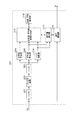
<スキャナ部>
図2は、スキャナ部の構造を例示的に示す断面図である。ここでは、リニアイメージセンサを用いたスキャナ部140の主要構成を示している。
<Scanner part>
FIG. 2 is a cross-sectional view illustrating the structure of the scanner unit. Here, the main configuration of the
原稿台ガラス1400は、読み取られるべき原稿100が置かれている。原稿100は照明ランプ1402により照射され、その反射光はミラー1403、1404、1405を経て、レンズ1406によりCCDセンサ1407上に結像される。ミラー1403、照明ランプ1402を含む第1ミラーユニット1409は速度vで移動し、ミラー1404、1405を含む第2ミラーユニット1410は速度1/2vで移動することにより、原稿100の前面を走査する。第1ミラーユニット1409及び第2ミラーユニット1410はモータ1408により駆動する。CCDセンサ1407に入力された反射光は、センサによって電気信号に変換され、その画素の電気信号は図示しないA/D変換器によってデジタルデータに変換され、後述のコントローラ200に画素信号Dinとして入力される。
On the
ここで、第1ミラーユニット1409および第2ミラーユニット1410の速度を変更することで、ミラーユニットの移動方向(副走査方向)の読取解像度を変更することが可能である。例えば副走査方向の読取解像度を600dpiとしたときの速度に対して2倍の速度で第1および第2ミラーユニットを移動させることで、読取解像度は300dpiになる。
Here, by changing the speeds of the
また、スキャナ部140は、原稿フィーダ141を動作させることによって原稿を読み取る“流し読み”で読取動作させることも可能である。流し読みにおいては、まず、原稿100をトレイ142上に置く。そして、原稿を駆動ローラ1401によってトレイ142から一度原稿台ガラス1400の面(駆動ローラ1401下部)を通って原稿フィーダ141上へ搬送させる。流し読みにおいては、第1ミラーユニット1409や第2ミラーユニット1410といった光学系は固定位置とし移動させない。すなわち、第1ミラーユニット1409は駆動ローラ1401下部の位置に固定されており、駆動ローラ1401によって駆動ローラ1401下部に搬送されてきた原稿を読み取る。この流し読みにおいては、原稿を一定方向に移動させればよいだけなので、大量の原稿を連続して高速に読み取ることが可能となる。
In addition, the
ここで、原稿の搬送速度を変更することで、原稿の移動方向(副走査方向)の読取解像度を変更することが可能である。例えば副走査方向の読取解像度を600dpiとしたときの速度に対して2倍の速度で原稿を搬送させることで、読取解像度は300dpiになる。このとき原稿の搬送速度が2倍になっているので生産性は600dpiの2倍になる。 Here, it is possible to change the reading resolution in the moving direction of the document (sub-scanning direction) by changing the document conveyance speed. For example, when the original is conveyed at a speed twice as high as the speed when the reading resolution in the sub-scanning direction is 600 dpi, the reading resolution becomes 300 dpi. At this time, since the document conveying speed is doubled, the productivity is doubled at 600 dpi.
また、リニアイメージセンサによっては設定に応じて主走査方向(センサの長手方向)の読み取り解像度を300dpiもしくは600dpiに変更できるものもある。 Some linear image sensors can change the reading resolution in the main scanning direction (longitudinal direction of the sensor) to 300 dpi or 600 dpi depending on the setting.
ところで、原稿100において、原稿100の読み取られる表面(照明ランプ1402によって光が照射される面)だけでなく、読み取られない面(裏面)にも写真やグラフ、文字などの何らかの画像が印刷されている場合がある。このとき、読み取られない面(裏面)の画像が表面の読み取り画像データに影響を及ぼす「裏写り」が発生することがある。これは、上記したどちらの読み取り方式であっても起こり得る。そして原稿100の紙などの媒体の厚み(光の透過率)や照明ランプ1402によって照射される光量によって程度が異なるものである。一般的に厚みの薄い紙が原稿であったり、照射される光量が多いほど裏写りの程度は大きくなる。また、裏面に印刷されている画像の濃度値にも影響を受け、高濃度な画像が印刷されている方が裏写りしやすい。
By the way, in the original 100, not only the surface of the original 100 to be read (the surface irradiated with light by the illumination lamp 1402) but also the non-readable side (the back) has some images such as photographs, graphs, and characters printed thereon. There may be. At this time, there may occur a “show-through” in which an image on the non-read side (back side) affects the read image data on the front side. This can occur with either of the reading methods described above. The degree varies depending on the thickness (light transmittance) of a medium such as paper of the
<複写機のハードウェア構成>
図3は、複写機1000のハードウェア構成を例示的に示す図である。コントローラ200は、画像入力デバイスであるスキャナ部140や、画像出力デバイスであるプリンタ120や、LAN10や、公衆回線(WAN)12と接続され、複写機1000の動作を統括的に制御すると共に画像情報やデバイス情報の入出力制御を行う。
<Hardware configuration of copier>
FIG. 3 is a diagram exemplarily showing a hardware configuration of the copying machine 1000. The
CPU2100は、複写機1000全体を制御するプロセッサであり、例えば、ROM2120に記憶された制御プログラム等に基づいて接続中の各種デバイスとのアクセスを統括的に制御する。さらに、CPU2100は、コントローラ200内部で行われる各種画像処理についても統括的に制御する。RAM2110は、システムワークメモリであり、画像データなどを一時記憶するための画像メモリでもある。ROM2120は、ブートROMであり、システムのブートプログラムを格納する。ハードディスクドライブ(HDD)2130は、主に、コンピュータを起動・動作させるために必要な情報(システムソフトウェア)や画像データを格納する。これらのデータは、HDD2130に限らず、電源が切れても記憶保持可能な記録媒体に格納してもよい。
The
LANコントローラ2200は、複写機1000をLAN10に接続し、ユーザPC20との間で出力用画像データの入出力や機器制御にかかわる情報の入出力を行う。ローカルインタフェース(I/F)2210は、USBやセントロニクス等のインタフェースであり、ケーブル11を介してユーザPC21と接続し、データの入出力を行う。MODEM2220は、複写機1000公衆回線12に接続し、不図示の遠隔地のPCなどとの間でデータの入出力を行う。
A
プリンタIF画像処理部2300は、プリンタ120と接続し、プリンタ120に搭載されたCPUと通信を行う。また、プリンタ画像処理部2300は、画像データの同期系/非同期系の変換やCPU2100の命令に従ってプリント出力のための画像処理を行う。スキャナIF画像処理部2400は、スキャナ部140と接続し、スキャナ部140に搭載されたCPUと通信を行う。また、スキャナ画像処理部2400は、画像データの同期系/非同期系の変換や後述する裏写り補正処理等の画像処理を行う。操作部インタフェース(I/F)2500は、操作ユニット160に表示する画像データをコントローラ200から操作ユニット160に出力するためのインタフェースである。また、操作部インタフェース(I/F)2500は、操作ユニット160を介して使用者が入力した情報をコントローラ200に出力するためのインタフェースでもある。
A printer IF
<スキャナ画像処理部>
図4は、実施例1におけるスキャナIF画像処理部2400の構成を示すブロック図である。シェーディング補正部2410は、スキャナ部140が出力する輝度を示す画素信号Din(図2参照)を入力として受ける。シェーディング補正部2410は、公知の技術を用いて光学系や撮像系の特性による輝度ムラに対して、一様な明るさの画像になるように補正処理を施す。シェーディング補正処理の施された画素信号Dshが後段のガンマ補正部2420に出力される。
<Scanner image processing unit>
FIG. 4 is a block diagram illustrating a configuration of the scanner IF
ガンマ補正部2420は、公知の技術を用いて、読み取り素子の色特性と機器の色特性との差を補償するための補正を行う。ガンマ補正処理が施された画素信号DgはスキャナIF画像処理部2400から出力されRAM2110へと書き込まれ、一時保存される。さらに、それと並行して画素信号Dgは裏写り補正処理部2430へ出力される。
The
裏写り補正処理部2430は、スキャナ部140で読み取った原稿の表面の読み取り画像データに裏写りが発生していた場合に、それを低減させる処理を実行する。なお、裏写り補正処理部2430は裏写り補正の指標となる裏写り補正情報の生成と、その補正情報を用いた裏写り補正処理の双方を実行するものである。裏写り補正処理の施された画素信号DuはスキャナIF画像処理部2400から出力され、図示しないメモリコントローラによってRAM2110へと書き込まれ、一時保存される。
The show-through
<裏写り補正処理部>
図5は、実施例1における裏写り補正処理部2430の構成を示すブロック図である。バッファ部2431は、画素信号Dgを一時記憶するバッファである。なお、画素信号Dgは、ディザ処理などの中間調処理された画像が印刷された原稿を読み取って得られた画素信号である。当該バッファは、後段で実行される明るさ成分の(たとえば輝度)分散値や平均値の算出、エッジ判定において注目画素を中心とした所定サイズのウィンドウ内の画素信号を参照するためのものである。例えば、後段の処理において、5×5のウィンドウ内の画素信号を参照する場合はバッファサイズは5ライン構成となり、7×7のウィンドウの場合はバッファサイズは7ライン構成となる。
<Back-through correction processing section>
FIG. 5 is a block diagram illustrating a configuration of the show-through
フィルタ処理部2432では、バッファ部2431からフィルタ処理に必要なウィンドウサイズ分の画素信号をまとめて受け取り、フィルタ処理を実行する。本フィルタ処理は原稿の同一網点内において、後述する裏写り除去のための補正量にバラつきが発生してしまうことを防ぐ目的で処理されるものである。よって、原稿内の網点周波数が、スキャナ部140の読み取り解像度によって決まる読み取りサンプリング周波数の1/2付近(ナイキスト周波数付近)であったとしても、フィルタ処理により、読み取った原稿データ内の網点成分を低減させることができる。本フィルタの設計例を図6に示す。図6の横軸は、dpi(dot/inch)を示しており、縦軸はフィルタ出力のパワーを示している。副走査方向に光学300dpiで画像を読み取る例を考える。このとき副走査方向のサンプリング周波数の1/2(ナイキスト周波数)は150dpiとなる。よって図6に示したような150dpi周辺の成分を低減させるフィルタ処理を副走査方向の画素成分に行うことで、読み取りサンプリング周波数の1/2付近(ナイキスト周波数付近)の成分を低減させることが可能となる。主走査方向に光学300dpiで画像を読み取る場合は、同様のフィルタ処理を主走査方向の画素成分に行えばよい。また異なる解像度で画像を読み取る場合は、その解像度に応じたナイキスト周波数を低減させるフィルタを通せば良い。フィルタ後の画素信号はバッファ部2433へ出力される。
The
バッファ部2433はフィルタ処理後の画素信号を一時記憶するバッファである。当該バッファは、後段で実行される分散値や平均値の算出、エッジ判定において注目画素を中心とした所定サイズのウィンドウ内の画素信号を参照するためのものである。例えば、後段の処理において、5×5のウィンドウ内の画素信号を参照する場合はバッファサイズは5ライン構成となり、7×7のウィンドウの場合はバッファサイズは7ライン構成となる。
The
分散値算出部2434は、バッファ部2433から算出に必要なウィンドウサイズ分の画素信号をまとめて受け取り、分散値(ばらつき度合い)の算出を実行する。例えば、分散値は以下の式(1)にしたがって計算される。
The variance

ここで、
N:注目ウィンドウ内の画素数
Xk:注目ウィンドウ内のk番目の画素信号値
Xa:注目ウィンドウ内の画素信号値の平均値
である。なお、分散値(σ2)は、値が大きくなりやすいので標準偏差値(σ)で代替してもよい。
here,
N: Number of pixels in the target window Xk: k-th pixel signal value in the target window Xa: Average value of pixel signal values in the target window The dispersion value (σ 2 ) may be replaced with a standard deviation value (σ) because the value tends to increase.
平均値算出部2435は、バッファ部2433から算出に必要なウィンドウサイズ分の画素信号をまとめて受け取り、当該ウィンドウサイズ分の画素値を代表する代表値として平均値の算出を実行する。例えば、平均値は以下の式(2)にしたがって計算される。
The average
各パラメータの定義は式(1)と同様である。なお、平均値算出に必要なウィンドウサイズと分散値算出に必要なウィンドウサイズは共通となるよう設定される。 The definition of each parameter is the same as in equation (1). The window size required for calculating the average value and the window size required for calculating the variance value are set to be the same.
エッジ判定部2436は、バッファ部2433から算出に必要なウィンドウサイズ分の画素信号をまとめて受け取り、注目画素がエッジ領域か否かの判定を実行する。エッジ判定は公知の技術を用いて行うものでよい。具体的には、PrewittフィルタやSobelフィルタを注目画素を中心としたウィンドウに適用し、算出結果を閾値判定し、画像エッジが存在する領域か否かを判定するものである。
The
分散値−平均値記憶制御部2437は、分散値−平均値記憶部2438へのデータの書き込みおよび読み出しを制御する。分散値−平均値記憶部2438は、LUTの形式で分散値毎の平均値を格納する。例えば分散値がLUTのアドレスになり、そのアドレスには分散値に対応した平均値がデータとして格納されるものである。まず、分散値−平均値記憶制御部2437は、エッジ判定部2436が出力したエッジ判定結果を参照し、エッジ領域か否かを確認する。エッジ領域であれば分散値−平均値記憶部2438へのデータの書き込みは行わない。次にエッジ領域でなかった場合、分散値−平均値記憶制御部2437は、分散値算出部2434が出力した分散値を参照し、同じ分散値となる分散値−平均値記憶部2438に記憶されている平均値を読みだす。すなわち、分散値算出部2434が算出した分散値と同じ分散値のLUTのアドレスにアクセスし、データ(平均値)を読みだす。次に分散値−平均値記憶制御部2437は、読みだした平均値と平均値算出部2435が算出した平均値を比較する。そして平均値算出部2435が出力した平均値の方が大きかった場合に、分散値−平均値記憶制御部2437は、その大きい平均値を分散値−平均値記憶部2438へ書き込む。つまり、読みだしたLUTのアドレスのデータを大きな値で更新する。さらに分散値−平均値記憶制御部2437は、分散値−平均値記憶部2438から読み出した平均値を補正量算出部2439へ出力する。
The variance value-average value
ここで、分散値−平均値記憶部2438から読み出した平均値の意味するところは、入力された画像の中で現在処理している注目画素に辿りつくまでに過去に処理してきた画像領域における最も明るい平均値というものである。この最も明るい平均値は、本実施例において裏写り補正情報(裏写り補正のための指標)になる。
Here, the mean value read from the variance value-average
ここで、分散値−平均値記憶部2438に記憶されるデータ(裏写り補正情報)の詳細な意味に関して、図7を用いて説明する。図7はスキャナ部140で読み取った原稿100の表面の読み取り画像データ300の一例である。原稿100の表面には、高濃度画像301(トラックの画像)、および、網点で表現された中間調画像302(矩形画像)のみが画像形成されている。また、原稿100の裏面(スキャナで読み取った面と逆の面)には高濃度画像301と同様の画像が画像形成されているものとする。このとき、スキャナ140で読み取った読み取り画像データ300には、原稿100の裏面に存在する高濃度画像が裏写り画像303(反転したトラックの画像)として発生している。この読み取り画像データ300の各領域の特徴について説明する。
Here, the detailed meaning of the data (show-through correction information) stored in the variance-average
中間調画像302の領域に注目した拡大図を中間調注目領域306として図示する。中間調注目領域306は、網点構造となっており、網点の打たれている領域と打たれていない領域に画素毎に分かれている。中間調注目領域306内の点線は読み取った画素の境目を示している。つまり、図7で示した例では網点の打たれている領域と打たれていない領域がそれぞれ2画素周期で発生しており、網点の1周期は、4画素の幅である。よって、図7は、原稿内の網点周波数が読み取り解像度によって決まるサンプリング周波数の1/4程度となった例である。ここで、この領域を所定のウィンドウサイズに区切って、画素濃度の分散値と平均値を算出し、分散値「X2」、平均値「Y2」とする。
An enlarged view focusing on the region of the
裏写り画像303の領域に注目した拡大図を裏写り注目領域304として図示する。裏写り注目領域304において、この領域を所定のウィンドウサイズに区切って画素濃度の分散値と平均値を算出し、分散値を「X1」、平均値を「Y3」とする。ここで、裏写り注目領域304で得られる分散値「X1」は小さな値となる。これは、一般に、裏面の画像の低周波成分のみが裏写り成分(紙を透過して得られた画像成分)として表れやすいためである。そのため、裏写り画像303に対応する裏面の画像が網点で描かれたものであったとしても、裏写り成分としては濃度(輝度)の凹凸なく発生することが多く、結果として分散値は小さな値となる。
An enlarged view focusing on the area of the show-through
また、読み取り画像データ300において、何も画像が存在せず、裏写りもしていない紙白領域を所定のウィンドウサイズに区切って得られた分散値を「X1」、平均値を「Y4」とする。なお、上述のように、裏写り成分は分散値に影響を及ぼしにくいので紙白領域の分散値と裏写り画像303の領域から得られる分散値は同じような値になりやすい。そのため、ここでは分散値を共通の「X1」としている。
Further, in the read
中間調画像302と裏写り画像303の重なった領域に注目した拡大図を、重なり注目領域305として図示する。重なり注目領域305は、網点構造なので網点の打たれている領域と打たれていない領域に画素毎に分かれている。しかしながら裏写り画像の影響を受け全体的に暗い(低輝度の)画素値となっている。重なり注目領域305において、この領域を所定のウィンドウサイズに区切って分散値と平均値を算出し、分散値を「X2」、平均値を「Y1」とする。なお、上述のように、裏写り成分は分散値に影響を及ぼしにくいので重なり注目領域305の分散値と裏写りしていない中間調画像302の中間調注目領域306から得られる分散値は、近似の値になる。そのため、ここでは分散値を共通の「X2」としている。
An enlarged view focusing on the overlapping area of the
図8は、読み取り画像データ300における明るさ成分(例えば、輝度)の分散値X1、X2および平均値Y1〜Y4の関係を示す図である。図8において、座標(X1、Y4)が紙白領域、座標(X1、Y3)が裏写り注目領域304、座標(X2、Y2)が中間調注目領域306、そして座標(X2、Y1)が重なり注目領域305を示す。すなわち、紙白領域が座標(X1、Y4)であって、紙白領域に裏写りが発生したものが座標(X1、Y3)と言える。また、中間調注目領域306が座標(X2、Y2)であって、中間調領域に裏写りが発生したものが座標(X2、Y1)と言える。図8の平均値は、明るさ(たとえば輝度)の平均値であり、Y4はY1よりも輝度が高いことを意味する。
FIG. 8 is a diagram showing the relationship between the brightness values (for example, luminance) variance values X1 and X2 and the average values Y1 to Y4 in the read
よって、裏写り注目領域304において、Y3とY4の差分量を用いて注目画素を補正することにより、裏写り領域の信号値は紙白領域の信号値へと補正され、適切に裏写り補正がされる。また、重なり注目領域305において、Y1とY2の差分量を用いて注目画素を補正することにより、重なり領域の信号値は中間調注目領域の信号値へと補正され、適切に裏写り補正がされる。言い換えると、各分散値において、裏写りしていない領域の平均値を裏写りを補正するための目標値(つまり裏写り補正情報)とすることができる。
Therefore, by correcting the target pixel using the difference amount between Y3 and Y4 in the show-through
ここで、明るさ成分の分散値は注目領域における網点の量に依存する。網点の量とは、例えば、注目領域の総画素数に対する該注目領域の有意画素の個数を百分率(0〜100%)で表され、画像濃度に応じて一意に決まるものである。よって、裏写り領域または裏写りと表面の網点が重なった領域が発生した場合においても、分散値毎の裏写りしていない平均値を目標として信号値を補正することで、裏写りを適切に補正できることがわかる。なお、「分散値毎の平均値を記憶」とは言い換えると「網点量毎の平均値を記憶」ということである。 Here, the variance value of the brightness component depends on the amount of halftone dots in the region of interest. The amount of halftone dots is expressed, for example, as a percentage (0 to 100%) of the number of significant pixels in the attention area with respect to the total number of pixels in the attention area, and is uniquely determined according to the image density. Therefore, even if there is a show-through area or an area where the show-through and the halftone dot on the surface overlap, correct the show-through by correcting the signal value for the average value that is not show-through for each variance value. It can be seen that it can be corrected. In addition, “storing the average value for each variance value” means “storing the average value for each halftone dot amount”.
ただし、適切な目標値を得るためには、裏写りしていない平均値を得る必要がある。これを簡易かつ適切に得るため、分散値−平均値記憶制御部2437にて説明したように、入力画像データにおいて分散値毎の最も高い平均値を目標値として用いているのである。これは、裏写りしていない領域の方が裏写りしている領域より高い(明るい)平均値を取ることを利用したものである。入力画像データ内の網点領域全体が裏写り領域に含まれてしまうことは稀であり、ほとんどの場合、裏写りしていない網点領域が存在するので本手法でも十分実用に耐えうるものになる。
However, in order to obtain an appropriate target value, it is necessary to obtain an average value that is not revealed. In order to obtain this easily and appropriately, as described in the dispersion value-average value
また、本実施例のように入力された画像の中で現在処理している注目画素に辿りつくまでに過去に処理してきた画像領域における最も明るい平均値を裏写り補正情報とした場合でも、適切な裏写り補正情報を記憶することが可能である。これは、実原稿において裏写り領域のみが連続して続くことは稀であることが理由であり、本実施例の形態であっても実用に耐えうると考えることができる。 Even if the brightest average value in the image area processed in the past until reaching the target pixel being processed in the input image as in this embodiment is used as the show-through correction information, it is appropriate. It is possible to store correct show-through correction information. This is because it is rare that only the show-through area continues in the actual document, and it can be considered that the present embodiment can withstand practical use.
次に図5の補正量算出部2439では、画素信号Dgを補正するための補正量を算出する。具体的には分散値−平均値記憶制御部2437から受け取った平均値から平均値算出部2435が算出した現在の注目領域における平均値の差を算出し、算出された差を補正量とする処理である。ここで、差が負の値となった場合には、注目領域における平均値は分散値−平均値記憶制御部2437に記憶してあった平均値より明るいという判断になるため補正量0とする。この補正量を補正処理部2440へ出力する。
Next, the correction
また、補正量算出部2439はエッジ判定部2436が出力するエッジ判定結果を参照し、エッジ部か否かを参照し、注目画素がエッジ部であるならば補正量0とする、または予め定めた所定の補正量とするなどの対応でもよい。また例えば、近傍の非エッジ部の補正量を参照し、その補正量を補正処理部2440へ出力するなどの対応でもよい。
Further, the correction
次に補正処理部2440では、補正量算出部2439から受け取った補正量を元として入力された画素信号Dgに裏写り補正処理を実行する。裏写り補正処理は、例えば画素信号Dgの輝度値に補正量を加算し、画素信号Dgを明るくするものである。このとき、入力された画素信号が裏写りしていない画素信号であれば差が小さくなり補正量は小さなものとなる。このほか、単純に補正量を加算するのではなく、入力された画素信号値に応じてゲインをかけて補正するものであってもよい。例えば、裏写りは入力された画素信号値が明るければ明るいほど影響を受けやすいので、画素信号の明るさに応じて、明るいほど強く補正するようなゲインをかけるものであってもよい。補正された画素信号値はDuとしてRAM2110へ書き戻される。
Next, the
また、分散値算出部2434の算出処理で得られる分散値は、画像のエッジ部などの画像境界では、異なる画像領域の影響を受け網点の量とは関係のない値になることがある。そこで、本実施例では、エッジ判定部2436にてエッジ検出し、エッジの存在する領域では裏写り補正を除外するような処理を行う。
Also, the variance value obtained by the calculation process of the variance
また、読み取った網点画像の分散値は注目領域(ウィンドウサイズ)内の網点の量50%を最大値の頂点として50%以上と未満で同じような分布を取る。そして網点の量0%もしくは100%で分散値は最小値を取る。これを図11に示す。図を参照すると異なる平均値で同一の分散値が発生している。しかしながら、このとき本裏写り補正処理は網点の量50%未満を対象とするものでよい。つまり、平均値の濃度が中間濃度となるところを境目としてそれ以下を対象にして補正させるものとしてよい。中間濃度以上であれば表面の濃度が高く裏写りの影響を受けにくいためである。このようにすることで分散値と平均値の関係は一意になる。さらに他の構成として50%以上の濃度である場合に補正量が小さくなるゲインを持ってもよい。これら網点量を考慮した処理は前述の補正処理部2440に実装される。
Further, the dispersion value of the read halftone image has a similar distribution with a halftone dot amount of 50% in the attention area (window size) as a maximum vertex and less than 50%. The dispersion value takes the minimum value when the amount of halftone dots is 0% or 100%. This is shown in FIG. Referring to the figure, the same variance value is generated with different average values. However, at this time, the show-through correction processing may be performed for an amount of less than 50% of halftone dots. That is, the correction may be performed with a place where the average density becomes an intermediate density as a boundary. This is because if the density is higher than the intermediate density, the surface density is high and is not easily affected by show-through. By doing so, the relationship between the variance value and the average value becomes unique. As another configuration, a gain that reduces the correction amount when the density is 50% or more may be provided. The processing considering the amount of halftone dots is implemented in the
なお、本処理は本実施例においては色毎に個別に実行する。よって分散値−平均値記憶部2438には色毎に個別に分散値毎の平均値が格納される。色毎に個別にすることで、裏写り成分がカラー(例えば赤い文字の裏写り成分など)であっても補正可能となる。
This process is executed individually for each color in this embodiment. Accordingly, the dispersion value-average
ここで、図10に分散値−平均値記憶部2438に構成されるLUTの一例を示す。1行目がLUTのアドレスを示し、2行目がLUTに格納されているデータを示す。このLUTのアドレスは分散値を示すものであるが、数値を小さくするために標準偏差(σ)として代替してもよい。標準偏差も数値の意味するところは分散値と同様にバラつき度を示すことに変わりない。ここでLUTに格納される分散値と平均値の関係について説明する。例えば分散値0(アドレス0)を示すアドレスは、裏写りの影響を考慮しないとベタ塗り部分か紙白部分かのどちらかとなる。ここで本LUTに格納される平均値は画像内で最も数値が高い(明るい)平均値なので、必然として分散値0のアドレスに格納される平均値は紙白の平均値となる。そして分散値(アドレス)が徐々に増えていくにつれて、画像内の網点の画素数が増えていくことになるので、格納される平均値(輝度データ)は低く(暗く)なっていく。よって、画像1ページを参照した後に形成されるLUTの各アドレスに格納されるデータは図10に示すような値となる。
Here, FIG. 10 shows an example of the LUT configured in the variance value-average
また、色毎に個別にするのではなく、色数分の次元を持つようにLUTを構成してもよい。例えば、RGB3色であれば[R分散値][G分散値][B分散値]で3次元を構成し、各色それぞれの平均値を格納するようにしてもよい。 Further, the LUT may be configured to have dimensions corresponding to the number of colors, instead of individually for each color. For example, in the case of RGB three colors, [R dispersion value], [G dispersion value], and [B dispersion value] may be configured in three dimensions, and the average value of each color may be stored.
<網点周波数が読み取り周波数のナイキスト周波数付近だった場合に関して>
読み取った原稿の網点周波数が、スキャナ部140の読み取り周波数のナイキスト周波数付近だった場合に関して、図9を用いて詳細に説明する。図9は、図7と同様の原稿を、図7とは異なる読み取り解像度で読み取った場合の例である。本図では、副走査方向(図の縦方向)の読み取り解像度が図7の半分のdpiになった場合の例である。つまり、図7の副走査方向の読み取り解像度を仮に600dpiとするならば、図9は副走査方向の読み取り解像度を300dpiとしたものである。
<When the halftone dot frequency is near the Nyquist frequency of the reading frequency>
A case where the halftone dot frequency of the read document is near the Nyquist frequency of the reading frequency of the
このときの中間調画像302の領域に注目したものを中間調注目領域307として図示する。ここで、図示した中間調の網点が副走査方向を基準として200線45度で印字されていた場合、副走査方向には200×1/√2の網点周波数となり141線となる。このとき副走査方向の読み取り解像度が300dpiならば、そのナイキスト周波数は150dpiとなり、網点の141線(dpi)はその付近となる。読み取り解像度のナイキスト周波数と網点周波数がこのように近い周波数になると、部分的に網点が解像されない領域が発生する。中間調注目領域307にそれを示す。中間調注目領域307では副走査方向に周期的に網点非解像領域308と網点解像領域309が発生する。
An area focused on the area of the
このような画像が裏写り補正処理部2430に入力され、仮にそのまま分散値を算出すると、網点解像領域309と網点非解像領域308で異なる分散値となり、異なる補正量となってしまう。これを防ぐためにフィルタ処理部2432にて読み取りサンプリング周波数の1/2付近(ナイキスト周波数付近)の成分を低減させるフィルタ処理を実行する。このようにすることで同一網点領域内に網点解像領域309と網点非解像領域308とで示したような領域が存在しても分散値をほぼ同一にすることができ、補正量もほぼ同一とすることができる。
If such an image is input to the show-through
<裏写り補正前処理のフローチャート>
図12は、実施例1における複写機1000の裏写り補正のための前処理の流れを示すフローチャートである。本フローチャートを実行することで、網点周波数がスキャナ部140の読み取りサンプリング周波数の1/2付近(ナイキスト周波数付近)であっても、同一網点内で補正量を一定とすることが可能となる。本フローチャートは、HDD2130に格納されたプログラムに従って、CPU2100がスキャナ部140を制御し原稿100の画像読取を実行する中で、スキャナIF画像処理部2400(特に裏写り補正処理部2430)を制御することで実行する。
<Flowchart of show-through correction pre-processing>
FIG. 12 is a flowchart illustrating the flow of preprocessing for show-through correction of the copying machine 1000 according to the first embodiment. By executing this flowchart, it is possible to make the correction amount constant within the same halftone dot even if the halftone dot frequency is around ½ of the reading sampling frequency of the scanner unit 140 (near the Nyquist frequency). . This flowchart is for controlling the scanner IF image processing unit 2400 (particularly the show-through correction processing unit 2430) while the
S101において、フィルタ係数を取得する。このフィルタ係数は読み取り光学解像度によって決まる読み取りサンプリング周波数の1/2付近の成分を低減させるものであって、スキャンモードや各種設定によって決定される光学解像度に合わせて適切に選択され、取得されるものである。 In S101, a filter coefficient is acquired. This filter coefficient reduces the component near the half of the reading sampling frequency determined by the reading optical resolution, and is selected and acquired appropriately according to the optical resolution determined by the scan mode and various settings. It is.
S102では、CPU2100はS101で取得したフィルタ係数をフィルタ処理部2432に設定し、フィルタ処理を実行する。これにより、読み取った画像内の網点成分に、読み取り光学解像度によって決まる読み取りサンプリング周波数の1/2付近の成分があった場合には、その成分はフィルタによって低減される。なお、読み取る原稿は、ディザ処理などの中間調処理された画像が印刷された原稿である。
In S102, the
以上で裏写り補正前処理のフローチャートは終了する。本フローチャートを実行することで、同一網点内で補正量を一定とできる。本フローチャート実行後に裏写り補正処理は実行される。 Thus, the flowchart of the show-through correction pre-processing ends. By executing this flowchart, the correction amount can be made constant within the same halftone dot. The show-through correction processing is executed after the execution of this flowchart.
<裏写り補正処理のフローチャート>
図13は、実施例1における複写機1000の裏写り補正処理の流れを示すフローチャートである。本フローチャートは、CPU2100がHDD2130に格納されたプログラムを実行し、スキャナIF画像処理部2400(特に補正処理部2440)を制御することで実行される。なお、本フローチャートは図12で示した裏写り補正前処理の後に実行する。
<Flowchart of show-through correction processing>
FIG. 13 is a flowchart illustrating the flow of show-through correction processing of the copying machine 1000 according to the first exemplary embodiment. This flowchart is executed by the
S201では、読み取られた画像に対してエッジ検出処理を実行する。これは、エッジ判定部2436にて実行されるもので読み取られた画像の注目画素を中心としたウィンドウ(バッファ部2433が出力)を参照し、公知の技術でエッジ検出するものである。
In S201, an edge detection process is executed on the read image. This is executed by the
S202では、S201のエッジ判定結果を参照し、注目画素がエッジ部か否かを判定する。エッジ部と判定された場合にはS209に進む。非エッジであればS203へ進む。 In S202, it is determined whether or not the target pixel is an edge portion by referring to the edge determination result in S201. If it is determined to be an edge portion, the process proceeds to S209. If it is a non-edge, the process proceeds to S203.
S203では、読み取られた画像における注目ウィンドウ内の輝度成分の分散値と平均値の算出を実行する。これは、分散値算出部2434および平均値算出部2435にて実行されるもので、読み取られた画像の注目画素を中心としたウィンドウ(バッファ部2433が出力)を参照し、算出する。
In S203, calculation of the variance value and average value of the luminance components in the window of interest in the read image is executed. This is executed by the variance
S204では、分散値−平均値記憶部2438のLUTからデータを読みだす。これは分散値−平均値記憶制御部2437にて実行されるもので、読み出すLUTのアドレスはS203で算出した分散値と同一のものである。読み出されたデータは裏写り補正情報となる。
In S204, data is read from the LUT of the variance value-average
S205では、S204で読み出した値とS203で算出した平均値のどちらが大きいかの比較を実行する。S204で読み出した値の方が大きければS207へ進む。S203で算出した平均値の方が大きければS206へ進む。 In S205, a comparison is made as to which of the value read in S204 and the average value calculated in S203 is greater. If the value read in S204 is larger, the process proceeds to S207. If the average value calculated in S203 is larger, the process proceeds to S206.
S206では、分散値−平均値記憶部2438へのLUTへデータの書き込み(更新)を実行する。書きこまれるデータはS203で算出した平均値であり、書き込むアドレスは、S203で算出した分散値である。
In S206, data is written (updated) to the LUT in the variance-average
S207では、裏写りのための補正量を算出する。これは補正量算出部2439にて実行されるものであって、S204で読み出した裏写り補正情報とS203で算出した平均値との差をとり、その差を補正量とするものである。
In S207, a correction amount for show-through is calculated. This is executed by the correction
S208では、入力された画素(S201における注目画素)に対して裏写り補正処理を実行する。これは補正処理部2440にて実行されるものであって、S207で算出した補正量を元として例えば入力された画素の信号値(輝度値)に補正量を加算し、画素信号Dgを明るくするものである。また入力された画素の信号値に、補正量に応じたゲインをかけるものであってもよい。例えば、画素が中間濃度よりも濃い場合は、裏写りしている可能性が低いため、画素の信号値に補正量を加算しない。画素が中間濃度よりも明るい場合は、裏写りしている可能性が高いため、補正量を加算する。
In S208, a show-through correction process is performed on the input pixel (the target pixel in S201). This is executed by the
S209では、S202でエッジ部と判定された場合にエッジ部補正処理を実行する。これは例えば、近傍の非エッジ部の補正量を参照し、その補正量をS208同様に入力された画素の信号値(輝度値)に加算し、画素信号Dgを明るくするものである。 In S209, an edge portion correction process is executed when the edge portion is determined in S202. For example, the correction amount of a non-edge portion in the vicinity is referred to, and the correction amount is added to the signal value (luminance value) of the input pixel as in S208 to brighten the pixel signal Dg.
以上で裏写り補正処理のフローチャートは終了する。図12のフローチャートおよび図13のフローチャートを実行することで、網点周波数と読み取り光学解像度の関係に依らず裏写りの影響を受けた画素信号値が適切に補正されるので、入力された画像内における裏写りの影響を低減させることが可能となる。 This is the end of the show-through correction processing flowchart. By executing the flowchart of FIG. 12 and the flowchart of FIG. 13, the pixel signal value affected by the show-through is appropriately corrected regardless of the relationship between the halftone dot frequency and the reading optical resolution. It is possible to reduce the influence of show-through in
また、本実施例では同一網点内で裏写り補正量を一定とするために読み取りサンプリング周波数の1/2付近(ナイキスト周波数付近)の網点周波数成分を低減させたが、この他の処理に適用させてもよい。例えば、像域分離処理のように網点領域とそれ以外の領域を識別判定するような処理である。このとき、同一網点内で網点が解像されている部分とされていない部分が混在すると弊害が発生するので、その前処理として本処理のようなナイキスト周波数付近の成分の低減処理を行ってもよい。 In this embodiment, the halftone dot frequency component in the vicinity of half of the reading sampling frequency (near the Nyquist frequency) is reduced in order to make the show-through correction amount constant within the same halftone dot. It may be applied. For example, it is a process of discriminating and determining a halftone dot area and other areas as in the image area separation process. At this time, if a portion where the halftone dot is not resolved and a portion where the halftone dot is not resolved are mixed in the same halftone dot, a detrimental effect occurs. Therefore, as a pre-processing, a component near the Nyquist frequency is reduced. May be.
実施例1では、裏写り補正前の画像にフィルタ処理を実行することで、網点周波数が原稿の読み取りサンプリング周波数の1/2付近(ナイキスト周波数付近)になったとしても同一網点内で補正量を一定とする方法および構成について述べた。 In the first embodiment, by performing filter processing on an image before show-through correction, even if the halftone dot frequency is about ½ of the original reading sampling frequency (near the Nyquist frequency), correction is performed within the same halftone dot. The method and configuration for keeping the amount constant have been described.
しかしながら、フィルタ処理では網点周波数が原稿の読み取りサンプリング周波数の1/2付近(ナイキスト周波数付近)でない画像に対しても少なからず影響を及ぼしてしまう。これは、図6で示したようなフィルタ特性がオーバーシュートや緩やかな傾きを含み、理想的なものにならないことに起因するものである。 However, the filter processing has a considerable influence even on an image whose halftone dot frequency is not about ½ of the original reading sampling frequency (near the Nyquist frequency). This is because the filter characteristics as shown in FIG. 6 include overshoots and gentle slopes and are not ideal.
実施例2では、原稿の網点周波数が読み取りサンプリング周波数の1/2付近(ナイキスト周波数付近)になった場合に、フィルタ処理を用いずに同一網点内で補正量を一定とする方法および構成について述べる。このような構成とすることで、網点周波数が原稿の読み取りサンプリング周波数の1/2付近(ナイキスト周波数付近)でない画像への裏写り補正前処理の影響を低減させることが目的である。また、フィルタ実装に比べ、実装コストを低減させることも可能である。 In the second embodiment, when the halftone dot frequency of the original is about ½ of the reading sampling frequency (near the Nyquist frequency), the correction amount is made constant within the same halftone dot without using the filter process. Is described. With such a configuration, it is an object to reduce the influence of pre-show-through correction processing on an image whose halftone frequency is not around ½ of the original reading sampling frequency (near the Nyquist frequency). In addition, the mounting cost can be reduced as compared with the filter mounting.
本実施例では実施例1に対して、裏写り補正処理部2430の内部構成および裏写り補正前処理に関する処理フローが異なる。複写機1000の外観およびスキャナ部140、スキャナIF画像処理部2400の構成やコントローラ200の構成は実施例1と同様である。以下、実施例1との差分について本実施例を詳細に説明する。
In this embodiment, the processing flow relating to the internal configuration of the show-through
<裏写り補正処理部>
図14は、実施例2における裏写り補正処理部2430の構成を示すブロック図である。
<Back-through correction processing section>
FIG. 14 is a block diagram illustrating a configuration of the show-through
バッファ部2441は画素信号Dgを一時記憶させておくバッファである。これは後段の平滑化判定処理において注目画素を中心としたウィンドウの参照が必要であるため、そのウィンドウを形成するためのバッファである。例えば平滑化処理において、5×5のウィンドウの参照が必要であればバッファサイズは5ラインとなる。なお、構成を簡略化する目的で平滑化処理で必要なウィンドウサイズと後段の分散値算出、平均値算出、エッジ判定で必要なウィンドウサイズを共通としておく。
The
平滑化判定処理部2442は、バッファ部2441から平滑化判定処理に必要なウィンドウサイズ分の画素信号をまとめて受け取り、平滑化判定処理を実行する。本判定処理は後述する裏写り除去のための補正量にバラつきが発生してしまうことを防ぐ目的で平滑化処理すべきか否かを判定するものである。そのために本判定処理は、原稿の読み取り光学解像度によって決まる読み取りサンプリング周波数の1/2付近(ナイキスト周波数付近)の成分が原稿内の注目ウィンドウ内の網点成分にあるか否かを簡易的に判定するものである。本判定処理の例を図15に示す。
The smoothing
図15は、5×5のウィンドウの参照によって平滑化判定をする場合の例を示したものである。図15において点線で示した領域が5x5のウィンドウであり、A〜Eがウィンドウ内の列番号を示し、1〜5がウィンドウ内の行番号を示す。 FIG. 15 shows an example in which smoothing determination is performed by referring to a 5 × 5 window. In FIG. 15, a region indicated by a dotted line is a 5 × 5 window, A to E indicate column numbers in the window, and 1 to 5 indicate row numbers in the window.
本判定処理の目的は読み取りサンプリング周波数の1/2付近(ナイキスト周波数付近)の網点成分が原稿内の注目ウィンドウ内にあるか否かを判断することにある。ここでは、それを1列毎(または1行毎)に判断していく処理とする。 The purpose of this determination processing is to determine whether or not a halftone dot component in the vicinity of half of the reading sampling frequency (near the Nyquist frequency) is within the window of interest in the document. Here, it is set as the process of judging it for every column (or every line).
ここで、読み取りサンプリング周波数の1/2の周波数成分が網点成分にあった場合を考える。このとき、サンプリング2画素で網点1周期となるので、サンプリング1画素単位で網点の有り/無しが切り替わるものである。よって例えば注目画素列に対して、輝度値がサンプリングの1画素単位でそのウィンドウ内の平均輝度値を中心として上下に変化しているならば読み取りサンプリング周波数の1/2の周波数成分が網点成分にあると簡易的に判断することが可能となる。 Here, a case is considered where the halftone dot component has a frequency component that is ½ of the read sampling frequency. At this time, since two sampling pixels form one halftone dot cycle, the presence / absence of halftone dots is switched in units of one sampling pixel. Therefore, for example, if the luminance value changes up and down around the average luminance value in the window in one pixel unit of sampling with respect to the pixel row of interest, the half frequency component of the reading sampling frequency is halftone dot component It is possible to easily determine that it is in the range.
ここで改めて図15に注目すると、縦方向のA列〜E列の5列にそのようなサンプリングの1画素単位での網点周期が確認できる。つまり、A〜E列でサンプリング周波数の1/2付近(ナイキスト周波数付近)の網点周波数を検出したものと判断でき、逆に横方向の1〜5行では検出していないものと判断できる。ここでは、どの列(または行)でナイキスト周波数を検出したかの情報を後段の平滑化処理部2443へ渡す。
Here, paying attention to FIG. 15 again, the halftone dot period in units of one pixel of such sampling can be confirmed in five columns from A column to E column in the vertical direction. That is, it can be determined that the halftone dot frequency near ½ of the sampling frequency (near the Nyquist frequency) is detected in columns A to E, and conversely, it can be determined that the halftone dot frequency is not detected in the first to fifth rows in the horizontal direction. Here, information on which column (or row) the Nyquist frequency is detected is passed to the subsequent
平滑化処理部2443では、5x5のウィンドウデータと平滑化判定処理部2442の出力した判定結果を用いて、平滑化を実行する。本実施例おいて、平滑化処理部2443は、平滑化判定処理部2442にてサンプリング周波数の1/2付近(ナイキスト周波数付近)の網点周波数であると判断された列(または行)の画素値を平均値で置換するものである。よって図15の例ではA〜Eすべての列がナイキスト周波数付近と判定されているので、5x5ウィンドウ内のすべての画素値が平均値に置換される。列または行のどちらか一方でもナイキスト周波数付近と判定されればその画素値は平均値へと置換されるものとする。置換された5x5ウィンドウデータが、後段の分散値算出部2434、平均値算出部2435、およびエッジ判定部2436へ出力される。
The smoothing
分散値算出部2434では実施例1と同様に分散値の算出を実行する。このとき、ウィンドウデータ内にサンプリング周波数の1/2付近(ナイキスト周波数付近)の網点周波数成分があったとしても前段の平滑化処理部2443で平滑化されているので、分散値は低く算出されることとなる。例えば図15の例のようにA〜E列すべてにおいて平滑化処理が実行されていれば分散値は0になる。
The variance
平均値算出部2435から補正処理部2440までの残りのブロックに関しては実施例1と同様のものである。
The remaining blocks from the average
<裏写り補正処理のフローチャート>
図16は、実施例2における複写機の裏写り補正前処理の流れを示すフローチャートである。本フローチャートを実行することで、網点周波数が読み取り光学解像度によって決まる読み取りサンプリング周波数の1/2付近(ナイキスト周波数付近)であっても同一網点内で補正量を一定とすることが可能となる。本フローチャートは、HDD2130に格納されたプログラムに従って、CPU2100がスキャナ部140を制御し原稿100の画像読取を実行する中で、スキャナIF画像処理部2400(特に裏写り補正処理部2430)を制御することで実行する。
<Flowchart of show-through correction processing>
FIG. 16 is a flowchart illustrating the flow of the show-through correction preprocessing of the copying machine according to the second embodiment. By executing this flowchart, it is possible to make the correction amount constant within the same halftone dot even if the halftone dot frequency is around half the reading sampling frequency determined by the reading optical resolution (near the Nyquist frequency). . This flowchart is for controlling the scanner IF image processing unit 2400 (particularly the show-through correction processing unit 2430) while the
S301では、読み取られた画像に対して特定周期性検出処理を実行する。特定すべき周期は、読み取りサンプリング周波数の1/2付近(ナイキスト周波数付近)である。これは、平滑化判定処理部2442にて実行されるもので、読み取られた画像の注目画素を中心としたウィンドウ(バッファ部2441が出力)を参照し、平均値を中心とした輝度の起伏から周期性を検出するものである。
In S301, a specific periodicity detection process is performed on the read image. The period to be specified is about ½ of the reading sampling frequency (near the Nyquist frequency). This is executed by the smoothing
S302では、CPU2100はS301の特定周期性検出結果を参照し、注目画素を含むウィンドウ内部に読み取りサンプリング周波数の1/2付近(ナイキスト周波数付近)の網点周波数成分が含まれているか否かを判定する。含まれていると判定された場合にはS303に進む。含まれていないと判定されたならば本フローチャートは終了となる。
In S <b> 302, the
S303では、CPU2100は平滑化処理を実行する。これは、平滑化処理部2443にて実行されるものである。S302にて読み取りサンプリング周波数の1/2付近(ナイキスト周波数付近)の網点周波数成分が含まれていると判断されたウィンドウ内部の領域に対して平均値置換などの平滑化処理を実行するものである。
In S303, the
以上で裏写り補正前処理のフローチャートは終了する。本フローチャート実行後に実施例1と同じく図13で示した裏写り補正処理を実行する。それにより、読み取りサンプリング周波数の1/2付近(ナイキスト周波数付近)の網点周波数成分の影響を排した状態で裏写り補正処理が適切に実行されるので、入力された画像内における裏写りの影響を低減させることが可能となる。 Thus, the flowchart of the show-through correction pre-processing ends. After executing this flowchart, the show-through correction process shown in FIG. 13 is executed as in the first embodiment. As a result, the show-through correction processing is appropriately executed in a state where the influence of the halftone dot frequency component in the vicinity of half of the reading sampling frequency (near the Nyquist frequency) is eliminated, and therefore the influence of the show-through in the input image. Can be reduced.
以上の本実施例の構成および処理によれば、特定周期性検出処理によって読み取りサンプリング周波数の1/2付近(ナイキスト周波数付近)の網点周波数成分が検出された場合に平滑化処理を実行することが可能となった。これにより本実施例は、実施例1のフィルタ処理よりも網点周波数が原稿の読み取りサンプリング周波数の1/2付近(ナイキスト周波数付近)でない画像への裏写り補正前処理の影響を低減させることが可能である。また、平滑化判定処理に用いるウィンドウサイズと分散値算出処理、平均値算出処理、およびエッジ判定に用いるウィンドウサイズを共通とし、平滑化処理をウィンドウデータ全体を対象にしてかけるようにしている。そのようにすることで、バッファを1つにまとめることができ、フィルタ実装に比べ、実装コストを低減させることが可能である。 According to the configuration and processing of the present embodiment described above, smoothing processing is executed when a halftone frequency component near the half of the reading sampling frequency (near the Nyquist frequency) is detected by the specific periodicity detection processing. Became possible. As a result, this embodiment can reduce the influence of the pre-show-out correction processing on the image whose halftone dot frequency is not around ½ of the original reading sampling frequency (near the Nyquist frequency) as compared with the filter processing of the first embodiment. Is possible. Further, the window size used for the smoothing determination process and the window size used for the variance value calculation process, the average value calculation process, and the edge determination are made common, and the smoothing process is applied to the entire window data. By doing so, the buffers can be combined into one, and the mounting cost can be reduced compared with the filter mounting.
(その他の実施例)
また、本発明は、以下の処理を実行することによっても実現される。即ち、上述した実施形態の機能を実現するソフトウェア(プログラム)を、ネットワーク又は各種記憶媒体を介してシステム或いは装置に供給し、そのシステム或いは装置のコンピュータ(またはCPUやMPU等)がプログラムを読み出して実行する処理である。
(Other examples)
The present invention can also be realized by executing the following processing. That is, software (program) that realizes the functions of the above-described embodiments is supplied to a system or apparatus via a network or various storage media, and a computer (or CPU, MPU, or the like) of the system or apparatus reads the program. It is a process to be executed.
Claims (8)
前記読取手段によって前記原稿を読み取って得られた画像データから、前記特定の読取解像度に基づいて決まるナイキスト周波数付近の周波数に対応する周期を有する網点領域を抽出する抽出手段と、
前記抽出手段によって抽出された網点領域に対して、平滑化処理を行う平滑化手段と、
前記平滑化手段によって平滑化処理された領域に対して、前記原稿の裏写りを除去するために明るさ補正を行う補正手段とを有することを特徴とする画像処理装置。 And a reading unit capable of read-document at a specific reading resolution,
Extraction means for extracting from the image data obtained by reading the document by the reading means , a halftone dot region having a period corresponding to a frequency near the Nyquist frequency determined based on the specific reading resolution ;
Smoothing means for performing a smoothing process on the halftone dot region extracted by the extracting means;
An image processing apparatus comprising: correction means for performing brightness correction on an area smoothed by the smoothing means to remove show-through of the document .
前記読取ステップによって読み取って得られた画像データから、前記特定の読取解像度に基づいて決まるナイキスト周波数付近の周波数に対応する周期を有する網点領域を抽出する抽出ステップと、
前記抽出ステップによって抽出された網点領域に対して、平滑化処理を行う平滑化ステップと、
前記平滑化ステップによって平滑化処理された領域に対して、前記原稿の裏写りを除去するために明るさ補正を行う補正ステップと
を有することを特徴とする画像処理方法。 A reading step for reading a document at a specific resolution ;
An extraction step of extracting a halftone dot region having a period corresponding to a frequency in the vicinity of the Nyquist frequency determined based on the specific reading resolution from the image data obtained by the reading step;
A smoothing step of performing a smoothing process on the halftone dot region extracted by the extraction step;
An image processing method comprising: a correction step of performing brightness correction on an area smoothed by the smoothing step in order to remove show-through of the document .
Priority Applications (2)
| Application Number | Priority Date | Filing Date | Title |
|---|---|---|---|
| JP2014128621A JP6338469B2 (en) | 2014-06-23 | 2014-06-23 | Image processing apparatus and image processing method |
| US14/745,082 US9565338B2 (en) | 2014-06-23 | 2015-06-19 | Image processing apparatus, method, and medium to perform image smoothing and brightness correction to remove show through |
Applications Claiming Priority (1)
| Application Number | Priority Date | Filing Date | Title |
|---|---|---|---|
| JP2014128621A JP6338469B2 (en) | 2014-06-23 | 2014-06-23 | Image processing apparatus and image processing method |
Publications (3)
| Publication Number | Publication Date |
|---|---|
| JP2016009941A JP2016009941A (en) | 2016-01-18 |
| JP2016009941A5 JP2016009941A5 (en) | 2017-08-03 |
| JP6338469B2 true JP6338469B2 (en) | 2018-06-06 |
Family
ID=54870809
Family Applications (1)
| Application Number | Title | Priority Date | Filing Date |
|---|---|---|---|
| JP2014128621A Active JP6338469B2 (en) | 2014-06-23 | 2014-06-23 | Image processing apparatus and image processing method |
Country Status (2)
| Country | Link |
|---|---|
| US (1) | US9565338B2 (en) |
| JP (1) | JP6338469B2 (en) |
Families Citing this family (8)
| Publication number | Priority date | Publication date | Assignee | Title |
|---|---|---|---|---|
| JP6797716B2 (en) * | 2017-02-28 | 2020-12-09 | キヤノン株式会社 | Image processing device and image processing method |
| JP7141257B2 (en) * | 2018-06-20 | 2022-09-22 | キヤノン株式会社 | IMAGE PROCESSING DEVICE, CONTROL METHOD THEREOF, AND PROGRAM |
| JP7282510B2 (en) * | 2018-12-07 | 2023-05-29 | キヤノン株式会社 | Image processing device, image processing method, and program |
| JP7169887B2 (en) * | 2019-01-15 | 2022-11-11 | キヤノン株式会社 | Image processing device, image processing method, and program |
| JP7250606B2 (en) * | 2019-04-25 | 2023-04-03 | キヤノン株式会社 | Image forming apparatus and its control method |
| JP7391653B2 (en) * | 2019-12-20 | 2023-12-05 | キヤノン株式会社 | Image processing device, image processing method, and program |
| WO2021138476A1 (en) * | 2019-12-30 | 2021-07-08 | Beijing Dajia Internet Information Technology Co., Ltd. | Coding of chrominance residuals |
| JP2022007228A (en) * | 2020-06-26 | 2022-01-13 | コニカミノルタ株式会社 | Image processing device, image formation apparatus and program |
Family Cites Families (20)
| Publication number | Priority date | Publication date | Assignee | Title |
|---|---|---|---|---|
| JP3135240B2 (en) * | 1989-08-24 | 2001-02-13 | 株式会社リコー | Image processing device |
| JPH03185574A (en) * | 1989-12-15 | 1991-08-13 | Fuji Xerox Co Ltd | Multivalued image filtering processor |
| JPH08271980A (en) * | 1995-03-30 | 1996-10-18 | Minolta Co Ltd | Image reader |
| JP3472479B2 (en) * | 1998-05-22 | 2003-12-02 | シャープ株式会社 | Image processing device |
| JP2001119575A (en) * | 1999-10-15 | 2001-04-27 | Ricoh Co Ltd | Image processing unit |
| JP2001320584A (en) * | 2000-05-08 | 2001-11-16 | Ricoh Co Ltd | Image processor and image forming device |
| US6621595B1 (en) * | 2000-11-01 | 2003-09-16 | Hewlett-Packard Development Company, L.P. | System and method for enhancing scanned document images for color printing |
| JP4509415B2 (en) * | 2001-04-12 | 2010-07-21 | 株式会社リコー | Image processing device |
| JP3713574B2 (en) * | 2001-05-29 | 2005-11-09 | コニカミノルタビジネステクノロジーズ株式会社 | Image processing apparatus, image processing method, and program |
| US7636492B2 (en) * | 2003-02-28 | 2009-12-22 | Hewlett-Packard Development Company, L.P. | Selective smoothing including bleed-through reduction |
| US7079687B2 (en) * | 2003-03-06 | 2006-07-18 | Seiko Epson Corporation | Method and apparatus for segmentation of compound documents |
| JP2004289570A (en) * | 2003-03-24 | 2004-10-14 | Minolta Co Ltd | Image processing method and image processing apparatus |
| US7590306B2 (en) * | 2003-11-26 | 2009-09-15 | Ge Medical Systems Global Technology Company, Llc | Resolution adaptive image filtering system and method |
| US7929798B2 (en) * | 2005-12-07 | 2011-04-19 | Micron Technology, Inc. | Method and apparatus providing noise reduction while preserving edges for imagers |
| JP4544311B2 (en) * | 2008-01-24 | 2010-09-15 | コニカミノルタビジネステクノロジーズ株式会社 | Image processing device |
| JP4700721B2 (en) * | 2008-10-10 | 2011-06-15 | 株式会社沖データ | Image processing device |
| JP5216799B2 (en) * | 2010-03-17 | 2013-06-19 | 京セラドキュメントソリューションズ株式会社 | Image processing apparatus and image forming apparatus |
| JP5645689B2 (en) | 2011-01-31 | 2014-12-24 | 京セラドキュメントソリューションズ株式会社 | Image processing apparatus and image forming apparatus having the same |
| JP5873400B2 (en) * | 2012-06-26 | 2016-03-01 | 株式会社沖データ | Image processing device |
| JP6182092B2 (en) * | 2014-03-10 | 2017-08-16 | キヤノン株式会社 | Image processing apparatus and image processing method |
-
2014
- 2014-06-23 JP JP2014128621A patent/JP6338469B2/en active Active
-
2015
- 2015-06-19 US US14/745,082 patent/US9565338B2/en active Active
Also Published As
| Publication number | Publication date |
|---|---|
| US9565338B2 (en) | 2017-02-07 |
| JP2016009941A (en) | 2016-01-18 |
| US20150373227A1 (en) | 2015-12-24 |
Similar Documents
| Publication | Publication Date | Title |
|---|---|---|
| JP6338469B2 (en) | Image processing apparatus and image processing method | |
| JP6182092B2 (en) | Image processing apparatus and image processing method | |
| JP4912270B2 (en) | Image processing apparatus and control method thereof | |
| JP6797716B2 (en) | Image processing device and image processing method | |
| US20140355010A1 (en) | Image processing apparatus and method thereof | |
| US20110181919A1 (en) | Image reading apparatus, control method thereof and computer-readable storage medium | |
| JP2009225113A (en) | Image forming apparatus, image forming method and image forming program | |
| US9571693B2 (en) | Image processing apparatus, image processing method, and program | |
| JP2012099946A (en) | Image processing device, control method for image processing device, and program | |
| US11032444B2 (en) | Image processing apparatus with enhanced show-through correction, and image processing method and storage medium therefor | |
| JP7391653B2 (en) | Image processing device, image processing method, and program | |
| JP4861506B2 (en) | Image processing apparatus and control method thereof | |
| JP6391348B2 (en) | Image processing apparatus, image processing method, and program | |
| US20110122462A1 (en) | Image reading apparatus, control method for the same, and image forming apparatus | |
| JP2014236445A (en) | Image processing system, image processing method and image reader | |
| JP4324532B2 (en) | Image processing apparatus and storage medium | |
| JP2003198838A (en) | Image processing system and image processing method | |
| JP2002199223A (en) | Image processor, image processing method and storage medium | |
| JP2018007023A (en) | Image processing device, image processing method and program | |
| JP2016163074A (en) | Image processing apparatus and image processing method, program | |
| JP2007067961A (en) | Image processor and image forming apparatus | |
| JP2011045063A (en) | Image processor and image processing method | |
| JP2006157447A (en) | Color image reader, image forming apparatus, and color correction method | |
| JP2011166734A (en) | Image processing apparatus and image processing method |
Legal Events
| Date | Code | Title | Description |
|---|---|---|---|
| A521 | Request for written amendment filed |
Free format text: JAPANESE INTERMEDIATE CODE: A523 Effective date: 20170622 |
|
| A621 | Written request for application examination |
Free format text: JAPANESE INTERMEDIATE CODE: A621 Effective date: 20170622 |
|
| A977 | Report on retrieval |
Free format text: JAPANESE INTERMEDIATE CODE: A971007 Effective date: 20180117 |
|
| A131 | Notification of reasons for refusal |
Free format text: JAPANESE INTERMEDIATE CODE: A131 Effective date: 20180123 |
|
| A521 | Request for written amendment filed |
Free format text: JAPANESE INTERMEDIATE CODE: A523 Effective date: 20180323 |
|
| TRDD | Decision of grant or rejection written | ||
| A01 | Written decision to grant a patent or to grant a registration (utility model) |
Free format text: JAPANESE INTERMEDIATE CODE: A01 Effective date: 20180410 |
|
| A61 | First payment of annual fees (during grant procedure) |
Free format text: JAPANESE INTERMEDIATE CODE: A61 Effective date: 20180508 |
|
| R151 | Written notification of patent or utility model registration |
Ref document number: 6338469 Country of ref document: JP Free format text: JAPANESE INTERMEDIATE CODE: R151 |