JP2017199976A - Image processing apparatus, image processing method and program - Google Patents

Image processing apparatus, image processing method and program Download PDF

Info

Publication number
JP2017199976A
JP2017199976A JP2016087386A JP2016087386A JP2017199976A JP 2017199976 A JP2017199976 A JP 2017199976A JP 2016087386 A JP2016087386 A JP 2016087386A JP 2016087386 A JP2016087386 A JP 2016087386A JP 2017199976 A JP2017199976 A JP 2017199976A
Authority
JP
Japan
Prior art keywords
edge
unit
determination
document
value
Prior art date
Legal status (The legal status is an assumption and is not a legal conclusion. Google has not performed a legal analysis and makes no representation as to the accuracy of the status listed.)
Pending
Application number
JP2016087386A
Other languages
Japanese (ja)
Inventor
雅明 村石
Masaaki Muraishi
雅明 村石
Current Assignee (The listed assignees may be inaccurate. Google has not performed a legal analysis and makes no representation or warranty as to the accuracy of the list.)
Canon Inc
Original Assignee
Canon Inc
Priority date (The priority date is an assumption and is not a legal conclusion. Google has not performed a legal analysis and makes no representation as to the accuracy of the date listed.)
Filing date
Publication date
Application filed by Canon Inc filed Critical Canon Inc
Priority to JP2016087386A priority Critical patent/JP2017199976A/en
Publication of JP2017199976A publication Critical patent/JP2017199976A/en
Pending legal-status Critical Current

Links

Images

Abstract

PROBLEM TO BE SOLVED: To provide a technique for preventing degradation of determination accuracy of a blank space due to false detection of edge in an image processing apparatus.SOLUTION: An edge detector in a blank page determination processing section detects a maximum value and a minimum value of pixel values in a region of a predetermined size in image data obtained by reading a document by a scanner (S111), and then calculates the difference value therebetween (S112). An edge detector generates an edge intensity signal by filtering the image data for extracting an edge (S113). When performing edge detection based on the edge intensity signal, the edge detector disables edge detection based on the edge intensity signal, when the calculated difference value is less than a first threshold (S114-S117). The blank page determination processing section determines whether or not a reading object document of the scanner is blank page, based on the edge detection results from the edge detector.SELECTED DRAWING: Figure 11

Description

本発明は、画像処理装置、画像処理方法及びプログラムに関するものである。   The present invention relates to an image processing apparatus, an image processing method, and a program.

デジタル複写機等の画像読取装置では、主に2種類の原稿読取方式が存在する。第1の方式は、原稿台ガラスに原稿を載置させることで原稿の位置を固定させた状態で光学系を移動させて原稿画像を読み取る方式(光学系移動方式)である。第2の方式は、光学系の位置を固定し、自動原稿搬送装置(ADF:Automatic Document Feeder)によって原稿を搬送させながら原稿画像を読み取る方式(流し読み方式)である。   In an image reading apparatus such as a digital copying machine, there are mainly two types of document reading methods. The first method is a method (optical system moving method) that reads an original image by moving an optical system in a state where the position of the original is fixed by placing the original on a platen glass. The second method is a method (flow-reading method) in which the position of the optical system is fixed and the original image is read while the original is conveyed by an automatic document feeder (ADF).

一般的に、ADFを用いる流し読み方式では、両面原稿と片面原稿とが混在していても、搬送される原稿の用紙の両面に対して読み取りを行っている。しかし、この方式では、片面に原稿画像が印刷された用紙の裏面の空白ページも読み取ることになり、これは空白ページの読み取りによって得られるデータを不必要に処理することにつながる。また、原稿の読み取りによって得られた画像データの出力(印刷)を行う場合に、そのような空白ページの印刷処理が実行されると、用紙及び電力を無駄に消費することになる。これに対し、原稿の読み取りによって得られた画像データから空白ページの画像データを判別して削除することで、用紙及び電力の無駄な消費を抑えることが可能となる。また、画像データを電子メール等の電子データとして送信する場合には、空白ページの画像データの削除によって、送信データ量を低減することが可能となる。   In general, in the scanning reading method using the ADF, even when a double-sided original and a single-sided original are mixed, reading is performed on both sides of the conveyed original paper. However, this method also reads a blank page on the back side of the paper on which the original image is printed on one side, which leads to unnecessary processing of data obtained by reading the blank page. Further, when outputting (printing) image data obtained by reading a document, if such blank page printing processing is executed, paper and power are wasted. On the other hand, wasteful consumption of paper and power can be suppressed by determining and deleting blank page image data from image data obtained by reading a document. In addition, when image data is transmitted as electronic data such as an e-mail, the amount of transmission data can be reduced by deleting image data of blank pages.

特許文献1では、原稿を読み取って得られた画像データが、空白ページ(無地原稿)を読み取って得られた画像データであるか否かを判定する技術が提案されている。具体的には、原稿を読み取って得られた画像データのヒストグラム及びエッジ画素数を求め、求めたヒストグラム及びエッジ画素数に基づいて、画像データが空白ページの画像データであるか否かを判定している。また、注目画素を含む複数の画素から成る所定ブロック内における最大濃度差とエッジ判定閾値とを比較することで、注目画素がエッジ画素であるか否かを判定(即ち、エッジを検出)している。   Japanese Patent Application Laid-Open No. 2004-228561 proposes a technique for determining whether image data obtained by reading a document is image data obtained by reading a blank page (a plain document). Specifically, the histogram and the number of edge pixels of the image data obtained by reading the document are obtained, and it is determined whether or not the image data is blank page image data based on the obtained histogram and the number of edge pixels. ing. Further, by comparing a maximum density difference in a predetermined block including a pixel of interest and an edge determination threshold with a predetermined block, it is determined whether the pixel of interest is an edge pixel (that is, an edge is detected). Yes.

特開2010−178377号公報JP 2010-178377 A

上述のように、所定ブロック内における最大濃度差に基づいてエッジを検出した場合、原稿画像の裏写りに起因する比較的振幅が小さいノイズ成分を、エッジとして誤検出することは避けられうる。しかし、例えば高周波または低周波の周波数成分を有するノイズを抑制しながら印刷情報に対応するエッジを強調するためのフィルタ処理を画像データに対して行う場合、裏写りに起因するノイズ成分も強調されてエッジの誤検出が発生する可能性がある。このようなエッジの誤検出は、エッジの検出結果に基づく空白ページの判定の精度を低下させることにつながる。   As described above, when an edge is detected based on the maximum density difference in a predetermined block, it is possible to avoid erroneously detecting a noise component having a relatively small amplitude due to the show-through of the original image as an edge. However, for example, when filter processing for emphasizing edges corresponding to print information is performed on image data while suppressing noise having high frequency or low frequency frequency components, noise components due to show-through are also emphasized. Edge detection may occur. Such an erroneous detection of the edge leads to a decrease in the accuracy of blank page determination based on the edge detection result.

本発明は、上述の問題に鑑みてなされたものである。本発明は、画像処理装置においてエッジの誤検出に起因した空白ページの判定精度の低下を防止する技術を提供することを目的とする。   The present invention has been made in view of the above problems. An object of the present invention is to provide a technique for preventing a decrease in blank page determination accuracy caused by erroneous detection of an edge in an image processing apparatus.

本発明は、例えば、画像処理装置として実現できる。本発明の一態様に係る画像処理装置は、原稿の読み取りによって得られた画像データにおける、複数の画素を含む所定サイズの領域内の画素値のうちで、最大値及び最小値を検出する検出手段と、エッジを抽出するためのフィルタ処理を前記画像データに対して行うことで、エッジ強度を示す強度信号を生成するフィルタ処理手段と、前記フィルタ処理手段によって生成された強度信号に基づいてエッジ検出を行うエッジ検出手段であって、前記最大値と前記最小値との差分が第1閾値未満であれば、前記強度信号に基づく前記エッジ検出を無効にする、前記エッジ検出手段と、前記エッジ検出手段によるエッジの検出結果に基づいて、前記読み取りの対象となった対象原稿が空白ページであるか否かを判定する第1判定手段と、を備えることを特徴とする。   The present invention can be realized as an image processing apparatus, for example. An image processing apparatus according to an aspect of the present invention is a detection unit that detects a maximum value and a minimum value among pixel values in a region of a predetermined size including a plurality of pixels in image data obtained by reading a document. And filtering processing for extracting edges on the image data to generate an intensity signal indicating edge strength, and edge detection based on the intensity signal generated by the filtering processing means Edge detection means for performing edge detection based on the intensity signal if the difference between the maximum value and the minimum value is less than a first threshold, and the edge detection First determination means for determining whether the target document to be read is a blank page based on the edge detection result by the means. The features.

本発明によれば、画像処理装置においてエッジの誤検出に起因した空白ページの判定精度の低下を防止することが可能になる。とりわけ、低周波及び高周波の周波数成分を有するノイズに起因したエッジの誤検出を抑制しながら裏写りによるノイズに起因したエッジの誤検出を抑制することが可能になり、それにより空白ページの判定精度をより高めることが可能になる。   According to the present invention, it is possible to prevent a decrease in blank page determination accuracy due to erroneous edge detection in an image processing apparatus. In particular, it is possible to suppress the false detection of edges due to noise caused by show-through while suppressing the false detection of edges due to noise having low frequency and high frequency components. Can be further enhanced.

複写機の構成例を示す外観図External view showing a configuration example of a copier スキャナ部110及び原稿フィーダ111の構成例を示す断面図Sectional drawing which shows the structural example of the scanner part 110 and the document feeder 111 複写機のハードウェア構成例を示すブロック図Block diagram showing a hardware configuration example of a copying machine 操作部120の構成例を示す外観図External view showing a configuration example of the operation unit 120 スキャナ画像処理部309及び空白ページ判定処理部504の構成例を示すブロック図A block diagram showing a configuration example of a scanner image processing unit 309 and a blank page determination processing unit 504 ヒストグラム生成部602、エッジ情報生成部604及びエッジ検出部704の構成例を示すブロック図A block diagram showing a configuration example of a histogram generation unit 602, an edge information generation unit 604, and an edge detection unit 704 ヒストグラム解析部603及びエッジ情報生成部604の構成例を示すブロック図A block diagram showing a configuration example of the histogram analysis unit 603 and the edge information generation unit 604 原稿の有効領域及び無効領域と領域分割の例を示す図The figure which shows the example of the effective area and invalid area of an original, and area division エッジ抽出部754で用いられるフィルタの周波数特性の例を示す図The figure which shows the example of the frequency characteristic of the filter used by the edge extraction part 754 複写処理の手順を示すフローチャートFlow chart showing the copy processing procedure エッジ検出処理の手順を示すフローチャートFlow chart showing the procedure of edge detection processing 用紙種別の設定画面の例を示す図Figure showing an example of the paper type setting screen

以下、本発明を実施するための形態について図面を用いて説明する。なお、以下の実施形態は特許請求の範囲に係る発明を限定するものでなく、また実施形態で説明されている特徴の組み合わせの全てが発明の解決手段に必須のものとは限らない。   Hereinafter, embodiments for carrying out the present invention will be described with reference to the drawings. The following embodiments do not limit the invention according to the claims, and all combinations of features described in the embodiments are not necessarily essential to the solution means of the invention.

[第1の実施形態]
第1の実施形態では、画像処理装置の一例として、複写(コピー)機能を有する複写機について説明する。なお、本実施形態は、複写機だけでなく、読取機能、印刷機能、複写機能等の多数の機能を有する複合機(MFP)、及びスキャナ等の画像読取装置から提供された画像データに対して画像処理を実行可能なPC等にも適用可能である。
[First Embodiment]
In the first embodiment, a copying machine having a copying function will be described as an example of an image processing apparatus. Note that this embodiment applies not only to a copying machine but also to image data provided from an image reading apparatus such as a multifunction peripheral (MFP) having a number of functions such as a reading function, a printing function, a copying function, and a scanner. The present invention can also be applied to a PC that can execute image processing.

<複写機>
図1は、第1の実施形態に係る複写機の構成例を示す外観図である。複写機は、プリンタ部100、スキャナ部110、原稿フィーダ111、及び操作部120を備えている。スキャナ部110は画像入力デバイスに相当し、プリンタ部100は画像出力デバイスに相当する。原稿フィーダ111は、自動原稿搬送装置(ADF)に相当する。複写機の内部にはコントローラ300(図3)が配置されている。
<Copier>
FIG. 1 is an external view showing a configuration example of a copying machine according to the first embodiment. The copying machine includes a printer unit 100, a scanner unit 110, a document feeder 111, and an operation unit 120. The scanner unit 110 corresponds to an image input device, and the printer unit 100 corresponds to an image output device. The document feeder 111 corresponds to an automatic document feeder (ADF). A controller 300 (FIG. 3) is arranged inside the copying machine.

スキャナ部110は、原稿上の画像を読み取って、当該画像に対応する画像データを生成し、生成した画像データをコントローラ300へ出力する、原稿の読取動作を行う。スキャナ部110による読取対象の原稿は、原稿フィーダ111のトレイ112、または原稿台ガラス211(図2)上にセットされる。スキャナ部110は、トレイ112から原稿を1枚ずつ搬送して当該原稿上の画像を読み取る動作モード(以下、「流し読みモード」と称する。)と、原稿台ガラス211上に置かれた原稿上の画像を読み取る動作モードとを有している。ユーザが操作部120を介して読取開始を指示すると、コントローラ300は、スキャナ部110に対して原稿読取指示を送信する。スキャナ部110は、コントローラ300から原稿読取指示を受信すると、それらの動作モードのいずれかで原稿の読取動作を行う。   The scanner unit 110 reads an image on a document, generates image data corresponding to the image, and outputs the generated image data to the controller 300 to perform a document reading operation. A document to be read by the scanner unit 110 is set on the tray 112 of the document feeder 111 or the document table glass 211 (FIG. 2). The scanner unit 110 conveys originals one by one from the tray 112 and reads an image on the original (hereinafter referred to as “flow-reading mode”), and on an original placed on the original platen glass 211. And an operation mode for reading the image. When the user instructs to start reading via the operation unit 120, the controller 300 transmits a document reading instruction to the scanner unit 110. Upon receiving a document reading instruction from the controller 300, the scanner unit 110 performs a document reading operation in any of these operation modes.

スキャナ部110は、照明ランプから出力された光によって原稿上の画像を露光及び走査して得られる反射光をリニアイメージセンサ(CCDセンサ)で受光し、当該CCDセンサによって画像の情報を電気信号に変換する。スキャナ部110は、CCDセンサから出力される電気信号をR,G,Bの各色から成る輝度信号に変換し、当該輝度信号を画像データとしてコントローラ300へ出力する。   The scanner unit 110 receives reflected light obtained by exposing and scanning an image on a document with light output from an illumination lamp by a linear image sensor (CCD sensor), and converts the image information into an electrical signal by the CCD sensor. Convert. The scanner unit 110 converts an electrical signal output from the CCD sensor into a luminance signal composed of R, G, and B colors, and outputs the luminance signal to the controller 300 as image data.

プリンタ部100は、コントローラ300から受信した画像データに基づいてシート(用紙)上に画像を形成する。なお、シートは、記録紙、記録材、記録媒体、用紙、転写材、転写紙等と称されてもよい。本実施形態のプリンタ部100は、一例として電子写真方式で画像形成を行う。プリンタ部100は、それぞれ異なる用紙サイズ及びそれぞれ異なる用紙の向きに対応可能な複数の用紙カセット101,102,103と、排紙トレイ104とを備えている。プリンタ部100は、用紙カセット101,102,103のいずれかから給紙した用紙に画像を形成し、画像が形成された用紙を排紙トレイ104に排紙する。   The printer unit 100 forms an image on a sheet (paper) based on the image data received from the controller 300. The sheet may be referred to as recording paper, recording material, recording medium, paper, transfer material, transfer paper, or the like. As an example, the printer unit 100 according to the present embodiment forms an image by an electrophotographic method. The printer unit 100 includes a plurality of paper cassettes 101, 102, and 103 that can correspond to different paper sizes and different paper orientations, and a paper discharge tray 104. The printer unit 100 forms an image on a sheet fed from one of the sheet cassettes 101, 102, and 103, and discharges the sheet on which the image is formed to a discharge tray 104.

<スキャナ部110及び原稿フィーダ111>
図2は、スキャナ部110及び原稿フィーダ111の構成例を示す断面図である。以下では、原稿フィーダ111を動作させ、流し読みモードでスキャナ部110が原稿の読取動作を行う場合について主に説明する。
<Scanner 110 and Document Feeder 111>
FIG. 2 is a cross-sectional view illustrating a configuration example of the scanner unit 110 and the document feeder 111. Hereinafter, a case where the document feeder 111 is operated and the scanner unit 110 performs a document reading operation in the flow-reading mode will be mainly described.

図2において、読取対象の原稿束202は、原稿フィーダ111のトレイ112上に置かれている。原稿フィーダ111からの原稿の搬送方向の下流には、送り出しローラ221、分離ローラ222及びレジストローラ223が順に配置されている。これらのローラを駆動する駆動源(図示せず)には、例えばステッピングモータが用いられる。送り出しローラ221は、トレイ112上に置かれた原稿束202を搬送路に送り出す。送り出しローラ221の下流に配置された分離ローラ222は、搬送されてきた原稿束202から最上位の原稿201を分離して下流へ搬送する。分離ローラ222によって搬送された原稿201は、回転が停止しているレジストローラ223の位置で停止する。その後、所定のタイミングにレジストローラ223の回転が開始することで、原稿201の搬送が再開される。レジストローラ223の回転が開始するタイミングは、原稿201の搬送タイミング及び画像読取タイミングの基準となる。   In FIG. 2, the document bundle 202 to be read is placed on the tray 112 of the document feeder 111. A delivery roller 221, a separation roller 222, and a registration roller 223 are sequentially arranged downstream in the conveyance direction of the document from the document feeder 111. For example, a stepping motor is used as a drive source (not shown) for driving these rollers. The feed roller 221 sends the document bundle 202 placed on the tray 112 to the transport path. A separation roller 222 disposed downstream of the feed roller 221 separates the uppermost document 201 from the conveyed document bundle 202 and conveys it downstream. The document 201 conveyed by the separation roller 222 stops at the position of the registration roller 223 where the rotation is stopped. Thereafter, when the rotation of the registration roller 223 starts at a predetermined timing, the conveyance of the document 201 is resumed. The timing at which the rotation of the registration roller 223 starts is a reference for the conveyance timing of the original 201 and the image reading timing.

レジストローラ223による搬送が開始された原稿201は、案内板227に沿って進んだ後大径の搬送ローラ224及び従動ローラ225a,225b,225cによって狭持されながら、搬送ローラ224の外周に沿って搬送される。このとき、原稿201は、原稿台ガラス211の面を通過する。原稿201が原稿台ガラス211の面を通過する際に、原稿201上の画像の読み取りが行われる。画像の読み取りが行われた後、原稿201は、搬送ローラ224の外周に沿って更に搬送される。その後、原稿201は、排紙ローラ226によって図2に示す矢印の方向へ等速で搬送されることで、原稿フィーダ111上に排出される。このような流し読みモードでは、大量の原稿を1枚ずつ一定の方向に搬送しながら連続して高速に原稿画像の読み取りを行うことが可能となる。   The document 201 that has started to be transported by the registration rollers 223 advances along the guide plate 227 and is then nipped by the large-diameter transport roller 224 and the driven rollers 225a, 225b, and 225c along the outer periphery of the transport roller 224 Be transported. At this time, the document 201 passes through the surface of the document table glass 211. When the document 201 passes through the surface of the document table glass 211, an image on the document 201 is read. After the image is read, the document 201 is further transported along the outer periphery of the transport roller 224. Thereafter, the document 201 is conveyed onto the document feeder 111 by being conveyed at a constant speed in the direction of the arrow shown in FIG. In such a flow reading mode, it is possible to continuously read a document image at a high speed while conveying a large amount of documents one by one in a certain direction.

次に、流し読みモードにおける原稿画像の読み取りについてより詳しく説明する。流し読みモードでは、上述のように、原稿台ガラス211の面を原稿201が通過する。このとき、第1ミラーユニット219及び第2ミラーユニット220は、モータ218によって移動され、図2に示す位置に配置されている。原稿201上の画像が原稿台ガラス211の面に相対するタイミングに、第1ミラーユニット219内の照明ランプ212によって、原稿201上の画像に光が照射される。原稿201からの反射光は、ミラー213,214,215で順に反射した後、レンズ216を通過してCCDセンサ217上に結像する。CCDセンサ217に入射した反射光は、CCDセンサ217によって各画素の電気信号に変換される。CCDセンサ217から出力される電気信号は、A/D変換器(図示せず)によってデジタルデータに変換され、当該デジタルデータは画素信号Dinとしてコントローラ300へ入力される。   Next, the reading of the document image in the flow reading mode will be described in more detail. In the flow-reading mode, the document 201 passes through the surface of the document table glass 211 as described above. At this time, the first mirror unit 219 and the second mirror unit 220 are moved by the motor 218 and arranged at the positions shown in FIG. Light is emitted to the image on the original 201 by the illumination lamp 212 in the first mirror unit 219 at a timing when the image on the original 201 is opposed to the surface of the original table glass 211. The reflected light from the original 201 is reflected by the mirrors 213, 214, and 215 in order, passes through the lens 216, and forms an image on the CCD sensor 217. The reflected light incident on the CCD sensor 217 is converted into an electric signal of each pixel by the CCD sensor 217. The electrical signal output from the CCD sensor 217 is converted into digital data by an A / D converter (not shown), and the digital data is input to the controller 300 as a pixel signal Din.

本実施形態のスキャナ部110では、棒状の光源を使用しており、当該光源の長手方向と平行に読み取りラインを設定している。原稿201は、この読み取りラインに対して直角の方向に搬送される。なお、本実施形態では、スキャナ部110における読み取りラインと平行の方向を主走査方向と定義し、読み取りラインに対して直角な方向(原稿搬送方向)を副走査方向と定義する。   In the scanner unit 110 of this embodiment, a rod-shaped light source is used, and a reading line is set in parallel with the longitudinal direction of the light source. The document 201 is conveyed in a direction perpendicular to the reading line. In the present embodiment, a direction parallel to the reading line in the scanner unit 110 is defined as a main scanning direction, and a direction perpendicular to the reading line (original transport direction) is defined as a sub-scanning direction.

スキャナ部110は、原稿台ガラス211上に置かれた原稿上の画像を読み取る動作モードで動作する場合には、原稿の置かれた原稿台ガラス211の下で、ミラー213及び照明ランプ212を含む第1ミラーユニット219を速度vで移動させる。更に、スキャナ部110は、ミラー214,215を含む第2ミラーユニット220を、第1ミラーユニット219の移動方向と同じ方向に速度v/2で移動させる。このようにして、原稿201上の画像を副走査方向に走査しながら読み取る。   When the scanner unit 110 operates in an operation mode for reading an image on a document placed on the document table glass 211, the scanner unit 110 includes a mirror 213 and an illumination lamp 212 under the document table glass 211 on which the document is placed. The first mirror unit 219 is moved at the speed v. Further, the scanner unit 110 moves the second mirror unit 220 including the mirrors 214 and 215 in the same direction as the movement direction of the first mirror unit 219 at a speed v / 2. In this way, the image on the original 201 is read while scanning in the sub-scanning direction.

<コントローラ300>
図3は、本実施形態に係る複写機のハードウェア構成例を示すブロック図である。コントローラ300は、プリンタ部100、スキャナ部110及び操作部120と接続されるとともに、LAN313及び公衆回線(WAN)317とも接続される。コントローラ300は、複写機全体の動作を制御するとともに、画像情報及びデバイス情報等の種々の情報(データ)の入出力制御を行う。
<Controller 300>
FIG. 3 is a block diagram illustrating a hardware configuration example of the copying machine according to the present embodiment. The controller 300 is connected to the printer unit 100, the scanner unit 110, and the operation unit 120, and is also connected to a LAN 313 and a public line (WAN) 317. The controller 300 controls the operation of the entire copying machine and controls input / output of various information (data) such as image information and device information.

CPU301は、複写機全体の動作を制御するプロセッサである。CPU301は、ROM303またはHDD(ハードディスクドライブ)304に格納された制御プログラムを読み出して実行することで、複写機内の各デバイスの動作を制御するとともに、コントローラ300内部で行われる各種処理についても制御する。RAM302は、CPU301が動作するためのシステムワークメモリであり、画像データ等が一時的に格納される画像メモリとしても用いられる。ROM303は、ブートROMであり、システムのブートプログラムが格納される。HDD(ハードディスクドライブ)304は、CPU301によって実行される種々のプログラム(システムソフトウェア、アプリケーションプログラム等)、及び画像データ等の種々のデータが格納される。なお、これらのデータは、HDD304以外の不揮発メモリ(記憶媒体)に格納されてもよい。   A CPU 301 is a processor that controls the operation of the entire copying machine. The CPU 301 reads out and executes a control program stored in the ROM 303 or the HDD (hard disk drive) 304, thereby controlling the operation of each device in the copying machine and controlling various processes performed in the controller 300. A RAM 302 is a system work memory for the CPU 301 to operate, and is also used as an image memory for temporarily storing image data and the like. A ROM 303 is a boot ROM, and stores a system boot program. The HDD (hard disk drive) 304 stores various programs (system software, application programs, etc.) executed by the CPU 301 and various data such as image data. These data may be stored in a non-volatile memory (storage medium) other than the HDD 304.

LANC(LANコントローラ)305は、LAN313に接続されており、LAN313を介して接続されるユーザPC314等の外部装置と通信するための通信インタフェース(IF)として機能する。CPU301は、LANC305を介して外部装置と通信可能であり、外部装置との間で画像データまたは制御情報(制御データ)の送受信を行うことが可能である。ローカルIF306は、USB等のIFであり、ケーブル315を介して接続されたユーザPC316またはプリンタとの間でデータの送受信を行う。モデム307は、公衆回線317に接続されており、公衆回線317を介して外部装置との間でデータ(例えば、FAXデータ)の送受信を行う。   A LANC (LAN controller) 305 is connected to the LAN 313 and functions as a communication interface (IF) for communicating with an external device such as the user PC 314 connected via the LAN 313. The CPU 301 can communicate with an external device via the LANC 305, and can transmit and receive image data or control information (control data) to and from the external device. The local IF 306 is an IF such as a USB, and transmits / receives data to / from the user PC 316 or the printer connected via the cable 315. The modem 307 is connected to the public line 317 and transmits / receives data (for example, FAX data) to / from an external device via the public line 317.

プリンタ画像処理部308は、プリンタ部100に対するプリンタIFとして機能し、プリンタ部100に搭載されたCPUと通信を行う。また、プリンタ画像処理部308は、画像データの同期系/非同期系の変換、及びプリンタ部100による画像形成(印刷)のための画像処理を画像データに対して行う。スキャナ画像処理部309は、スキャナ部110に対するスキャナIFとして機能し、スキャナ部110に搭載されたCPUと通信を行う。なお、原稿フィーダ111は、スキャナ部110を介してスキャナ画像処理部309と接続されている。また、スキャナ画像処理部309は、画像データの同期系/非同期系の変換、及びスキャナ部110による原稿画像の読み取りによって得られる画像データに対する画像処理(例えば、後述する空白ページの判定処理等)を行う。   The printer image processing unit 308 functions as a printer IF for the printer unit 100 and communicates with a CPU mounted on the printer unit 100. The printer image processing unit 308 also performs image processing for image data (synchronous / asynchronous conversion) and image formation (printing) by the printer unit 100 on the image data. The scanner image processing unit 309 functions as a scanner IF for the scanner unit 110 and communicates with a CPU mounted on the scanner unit 110. The document feeder 111 is connected to the scanner image processing unit 309 via the scanner unit 110. Also, the scanner image processing unit 309 performs image processing (for example, blank page determination processing described later) on image data obtained by synchronous / asynchronous conversion of image data and reading of an original image by the scanner unit 110. Do.

画像回転部310は、操作部120を介してユーザによって設定された処理条件または原稿の向きに基づいて、入力された画像データに対する回転処理を行う。画像圧縮伸張部311は、多値の画像データをJPEGの画像データに圧縮する処理、2値の画像データをJBIG、MMR、MH等の画像データに圧縮する処理、及び圧縮された画像データを伸長する処理を行う。操作部IF312は、操作部120に対するIFとして機能する。操作部IF312は、操作部120に表示する操作画面の画像データを、コントローラ300側から操作部120へ出力する。また、操作部IF312は、操作部120を介してユーザによって入力された情報を、操作部120からコントローラ300側へ出力する。   The image rotation unit 310 performs rotation processing on the input image data based on the processing conditions set by the user via the operation unit 120 or the orientation of the document. The image compression / decompression unit 311 compresses multi-value image data into JPEG image data, compresses binary image data into image data such as JBIG, MMR, and MH, and decompresses the compressed image data Perform the process. The operation unit IF 312 functions as an IF for the operation unit 120. The operation unit IF 312 outputs image data of an operation screen displayed on the operation unit 120 from the controller 300 side to the operation unit 120. The operation unit IF 312 outputs information input by the user via the operation unit 120 from the operation unit 120 to the controller 300 side.

<操作部120>
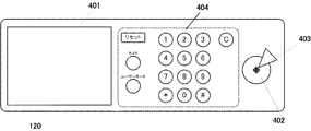
図4は、操作部120の構成例を示す外観図である。操作パネル401は、液晶ディスプレイとタッチパネルとを組み合わせたものである。操作パネル401は、操作画面を表示するとともに、操作画面に対するユーザのタッチ操作を受け付けてその操作内容を示す情報をコントローラ300へ送信する。スタートキー402は、複写(コピー機能)または読取機能等の、複写機が有する機能の実行開始を指示するために用いられる。
<Operation unit 120>
FIG. 4 is an external view illustrating a configuration example of the operation unit 120. The operation panel 401 is a combination of a liquid crystal display and a touch panel. The operation panel 401 displays an operation screen, receives a user's touch operation on the operation screen, and transmits information indicating the operation content to the controller 300. A start key 402 is used to instruct the start of execution of a function of the copying machine such as copying (copying function) or reading function.

スタートキー402には、緑色及び赤色の2色のLEDが組み込まれており、緑色のLEDの点灯は開始指示が可能であることを示し、赤色のLEDの点灯は開始指示が不可能であることを示す。ストップキー403は、実行中の動作の停止を指示するために用いられる。ハードキー群404には、テンキー、クリアキー、リセットキー、ガイドキー、及びユーザーモードキーが設けられる。   The start key 402 incorporates green and red LEDs, and lighting of the green LED indicates that a start instruction is possible, and lighting of the red LED cannot be instructed to start. Indicates. A stop key 403 is used to instruct to stop the operation being executed. The hard key group 404 includes a ten key, a clear key, a reset key, a guide key, and a user mode key.

<スキャナ画像処理部309>
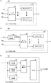
図5(A)は、スキャナ画像処理部309の構成例を示すブロック図である。スキャナ画像処理部309は、レジスタ(図示せず)と接続されており、当該レジスタには制御用パラメータが設定される。スキャナ画像処理部309は、レジスタに設定された制御用パラメータに基づいて動作する。レジスタへの書き込みは、CPU301及びスキャナ画像処理部309によって行われる。スキャナ画像処理部309は、シェーディング補正部501、ガンマ補正部502、DMAC503、及び空白ページ判定処理部504によって構成される。
<Scanner Image Processing Unit 309>
FIG. 5A is a block diagram illustrating a configuration example of the scanner image processing unit 309. The scanner image processing unit 309 is connected to a register (not shown), and a control parameter is set in the register. The scanner image processing unit 309 operates based on the control parameters set in the register. Writing to the register is performed by the CPU 301 and the scanner image processing unit 309. The scanner image processing unit 309 includes a shading correction unit 501, a gamma correction unit 502, a DMAC 503, and a blank page determination processing unit 504.

スキャナ画像処理部309に入力された画素信号Din(画像データ)は、シェーディング補正部501に入力される。シェーディング補正部501は、入力された画素信号Dinに対してシェーディング補正を行い、シェーディング補正が行われた画素信号Dhをガンマ補正部502へ出力する。シェーディング補正は、光学系の特性に起因して生じる輝度ムラを除くための補正処理である。   The pixel signal Din (image data) input to the scanner image processing unit 309 is input to the shading correction unit 501. The shading correction unit 501 performs shading correction on the input pixel signal Din, and outputs the pixel signal Dh subjected to the shading correction to the gamma correction unit 502. The shading correction is a correction process for removing luminance unevenness caused by the characteristics of the optical system.

ガンマ補正部502は、入力された画素信号Dhに対してガンマ補正を行い、ガンマ補正が行われた画素信号Dgを、DMAC(DMAコントローラ)503及び空白ページ判定処理部504へ出力する。ガンマ補正は、スキャナ部110(CCDセンサ217)の色特性とスキャナ部110の出力側の機器の色特性との差を補正するための補正処理である。DMAC503は、ガンマ補正部502から出力された画素信号Dgを、CPU301を介さずに、直接、画像メモリ(RAM302)の指定された領域へ画像データDoutとして書き込むための制御を行う。   The gamma correction unit 502 performs gamma correction on the input pixel signal Dh, and outputs the pixel signal Dg subjected to gamma correction to the DMAC (DMA controller) 503 and the blank page determination processing unit 504. The gamma correction is a correction process for correcting a difference between the color characteristics of the scanner unit 110 (CCD sensor 217) and the color characteristics of the device on the output side of the scanner unit 110. The DMAC 503 performs control for writing the pixel signal Dg output from the gamma correction unit 502 as image data Dout directly into a specified area of the image memory (RAM 302) without using the CPU 301.

空白ページ判定処理部504は、以下で詳細に説明するように、入力された画素信号Dg(画像データ)に基づいて、スキャナ部110によって読み取られた原稿(対象原稿)が空白ページであるか否かを判定する処理を行う。言い換えれば、空白ページ判定処理部504は、スキャナ部110によって原稿(対象原稿)を読み取って得られた画像データが空白ページの画像データであるか否かを判定する処理を行う。   As will be described in detail below, the blank page determination processing unit 504 determines whether the document (target document) read by the scanner unit 110 is a blank page based on the input pixel signal Dg (image data). The process which determines is performed. In other words, the blank page determination processing unit 504 determines whether or not the image data obtained by reading the document (target document) by the scanner unit 110 is blank page image data.

<空白ページ判定処理部504>
図5(B)は、空白ページ判定処理部504の構成例を示すブロック図である。空白ページ判定処理部504は、レジスタ(図示せず)と接続されており、当該レジスタには制御用パラメータが設定されるとともに処理結果が保持される。空白ページ判定処理部504は、レジスタに設定された制御用パラメータに基づいて動作する。レジスタへの書き込みは、CPU301及び空白ページ判定処理部504によって行われる。空白ページ判定処理部504は、領域制御部601、ヒストグラム生成部602、ヒストグラム解析部603、エッジ情報生成部604、エッジ情報解析部605、及び空白ページ判定部606によって構成される。なお、図6及び図7は、ヒストグラム生成部602、ヒストグラム解析部603、エッジ情報生成部604、エッジ情報解析部605の具体的な構成例を示している。
<Blank Page Determination Processing Unit 504>
FIG. 5B is a block diagram illustrating a configuration example of the blank page determination processing unit 504. The blank page determination processing unit 504 is connected to a register (not shown), in which control parameters are set and processing results are held. The blank page determination processing unit 504 operates based on the control parameter set in the register. Writing to the register is performed by the CPU 301 and the blank page determination processing unit 504. The blank page determination processing unit 504 includes an area control unit 601, a histogram generation unit 602, a histogram analysis unit 603, an edge information generation unit 604, an edge information analysis unit 605, and a blank page determination unit 606. 6 and 7 illustrate specific configuration examples of the histogram generation unit 602, the histogram analysis unit 603, the edge information generation unit 604, and the edge information analysis unit 605.

本実施形態では、空白ページ判定処理部504は、入力された画像データに基づいて、ヒストグラム及びエッジ情報(エッジ数を示す情報)を生成する。生成されるヒストグラムは、画素信号Dgによって表現される階調値(輝度値)の度数分布に相当し、例えば画素信号Dgのビット精度が8ビット(256階調)である場合、256階調のそれぞれの階調値の度数の分布に相当する。また、生成されるエッジ情報は、対象領域内のエッジ数を示す情報に相当する。更に、空白ページ判定処理部504は、生成したヒストグラム及びエッジ情報の解析結果に基づいて、対象原稿が空白ページであるか否かを判定する処理を行う。以下では、領域制御部601、ヒストグラム生成部602、ヒストグラム解析部603、エッジ情報生成部604、エッジ情報解析部605、及び空白ページ判定部606のそれぞれの構成及び動作について詳細に説明する。   In the present embodiment, the blank page determination processing unit 504 generates a histogram and edge information (information indicating the number of edges) based on the input image data. The generated histogram corresponds to a frequency distribution of gradation values (luminance values) expressed by the pixel signal Dg. For example, when the bit accuracy of the pixel signal Dg is 8 bits (256 gradations), the gradation of 256 gradations is obtained. This corresponds to the frequency distribution of each gradation value. The generated edge information corresponds to information indicating the number of edges in the target area. Further, the blank page determination processing unit 504 performs a process of determining whether or not the target document is a blank page based on the generated histogram and edge information analysis result. Hereinafter, the configurations and operations of the region control unit 601, the histogram generation unit 602, the histogram analysis unit 603, the edge information generation unit 604, the edge information analysis unit 605, and the blank page determination unit 606 will be described in detail.

(領域制御部601)
空白ページ判定処理部504に入力された画素信号Dgは、スキャナ部110によって読み取られた原稿に対応する画像データとして領域制御部601に入力される。領域制御部601は、入力される画像データからヒストグラム及びエッジ情報を生成するための、原稿の領域を制御する。
(Region Control Unit 601)
The pixel signal Dg input to the blank page determination processing unit 504 is input to the area control unit 601 as image data corresponding to the document read by the scanner unit 110. A region control unit 601 controls a document region for generating histogram and edge information from input image data.

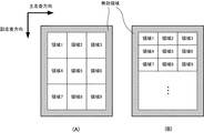
ここで、図8は、本実施形態における、原稿の有効領域及び無効領域と領域分割の例を示す図である。スキャナ部110による原稿の読み取りでは、読取対象の原稿の端部(例えば、原稿の搬送方向における先端、後端、左端及び右端)の読み取りが適切に行えず、原稿の影が発生することがある。これは、原稿の搬送系(原稿フィーダ111)の構成及びスキャナ部110の光源の構成に依存して発生する。原稿の影部分の画像データがヒストグラム及びエッジ情報の生成に用いられると、空白ページ判定処理部504による判定精度が低下する。   Here, FIG. 8 is a diagram showing an example of the valid area and invalid area of the document and area division in the present embodiment. When the original is read by the scanner unit 110, the end of the original to be read (for example, the front end, the rear end, the left end, and the right end in the original transport direction) cannot be appropriately read, and a shadow of the original may occur. . This occurs depending on the configuration of the document transport system (document feeder 111) and the configuration of the light source of the scanner unit 110. When the image data of the shadow portion of the document is used for generating the histogram and the edge information, the determination accuracy by the blank page determination processing unit 504 decreases.

このため、領域制御部601は、そのような影部分を特定し、影部分の画像データがヒストグラム及びエッジ情報の生成に用いられないよう、当該影部分を無効領域として設定し、影部分以外の部分を有効領域として予め設定する。領域制御部601は、現在入力されている画素信号Dgに対応する画素の原稿上の位置が、有効領域であるか無効領域かを判定し、その判定結果を示す領域判定信号701(図6)を生成する。   For this reason, the area control unit 601 identifies such a shadow part, sets the shadow part as an invalid area so that the image data of the shadow part is not used for generation of the histogram and edge information, and other than the shadow part. The part is preset as an effective area. The area control unit 601 determines whether the position of the pixel corresponding to the currently input pixel signal Dg on the document is an effective area or an invalid area, and an area determination signal 701 indicating the determination result (FIG. 6). Is generated.

更に、領域制御部601は、原稿の有効領域を主走査方向及び副走査方向においてそれぞれ複数の領域に分割する。本実施形態では、原稿の有効領域を、図8(A)に示すように領域1〜領域9の9個の領域に分割する例について説明する。このような領域分割は、後述するように、入力される画像データから領域ごとにヒストグラム及びエッジ情報を生成するために行われる。   Further, the area control unit 601 divides the effective area of the document into a plurality of areas in the main scanning direction and the sub-scanning direction. In the present embodiment, an example will be described in which an effective area of a document is divided into nine areas, area 1 to area 9, as shown in FIG. As described later, such region division is performed to generate histograms and edge information for each region from input image data.

ここで、原稿の領域全体の画像データからヒストグラムを生成した場合、少量の文字が局所的に印刷された原稿と、原稿の用紙に含まれる不純物が全体に分布した、空白ページの原稿とを、当該ヒストグラムに基づいて判別することは難しい可能性がある。これに対し、図8(A)に示すように、原稿の領域(有効領域)を分割して得られる複数の領域(分割領域)のそれぞれのヒストグラムを生成した場合、領域間のヒストグラムの差異に基づいてそのような判別を適切に行うことが可能になる。   Here, when a histogram is generated from image data of the entire area of the original, an original on which a small amount of characters is printed locally and an original on a blank page in which impurities contained in the original paper are distributed over the whole, It may be difficult to determine based on the histogram. On the other hand, as shown in FIG. 8A, when histograms of a plurality of areas (divided areas) obtained by dividing an area (effective area) of a document are generated, the difference in histogram between the areas is determined. Based on this, it is possible to appropriately make such a determination.

また、原稿の領域全体の画像データからエッジ情報を生成した場合も、少量の文字が局所的に印刷された原稿と、原稿の用紙に含まれる不純物が全体に分布した、空白ページの原稿とを、当該エッジ情報に基づいて判別することは難しい可能性がある。これに対し、図8(A)に示すように、原稿の領域を分割して得られる領域ごとにエッジ情報を生成した場合、領域間のエッジ数の差異(ばらつき)に基づいて、そのような判別を適切に行うことが可能になる。   In addition, when edge information is generated from image data of the entire area of the original, an original on which a small amount of characters is printed locally and a blank page original in which impurities contained in the original paper are distributed throughout It may be difficult to determine based on the edge information. On the other hand, as shown in FIG. 8A, when the edge information is generated for each area obtained by dividing the area of the document, such a difference is determined based on the difference (variation) in the number of edges between the areas. Discrimination can be performed appropriately.

領域制御部601は、現在入力されている画素信号Dgに対応する画素の原稿上の位置が、分割後の複数の領域(領域1〜9)のうちのいずれの領域内であるかを示す領域信号702(図6)を生成する。領域制御部601は、生成した領域判定信号701及び領域信号702を、入力された画像信号Dgとともに、ヒストグラム生成部602及びエッジ情報生成部604に対して出力する。   The area control unit 601 indicates which of the plurality of divided areas (areas 1 to 9) the position of the pixel corresponding to the currently input pixel signal Dg on the document is. A signal 702 (FIG. 6) is generated. The region control unit 601 outputs the generated region determination signal 701 and region signal 702 to the histogram generation unit 602 and the edge information generation unit 604 together with the input image signal Dg.

なお、原稿フィーダ111を用いる流し読みモードでは、スキャナ部110による読取開始の時点で読取対象の原稿の副走査方向(原稿搬送方向)のサイズが確定していていない場合がある。原稿の副走査方向のサイズが確定しなければ、図8(A)に示すような領域分割を行うことができない。この場合、図8(B)に示すように、副走査方向において所定サイズの領域を繰り返し配置することで副走査方向の領域分割を行ってもよい。   Note that, in the continuous scanning mode using the document feeder 111, there is a case where the size of the document to be read in the sub-scanning direction (document transport direction) is not fixed at the start of scanning by the scanner unit 110. If the size of the original in the sub-scanning direction is not fixed, the area division as shown in FIG. 8A cannot be performed. In this case, as shown in FIG. 8B, region division in the sub-scanning direction may be performed by repeatedly arranging regions of a predetermined size in the sub-scanning direction.

(ヒストグラム生成部602)
図6(A)は、ヒストグラム生成部602の構成例を示すブロック図である。ヒストグラム生成部602は、画素信号Dg、領域判定信号701及び領域信号702に基づいて、領域分割によって得られた領域ごとにヒストグラムを生成する。即ち、ヒストグラム生成部602は、領域1〜9(複数の分割領域)のそれぞれについて、画素値の度数分布を示すヒストグラム(第1〜第9ヒストグラム)を生成する。更に、ヒストグラム生成部602は、第1〜第9ヒストグラムから成るヒストグラムセット710を、ヒストグラム解析部603へ出力する。
(Histogram generation unit 602)
FIG. 6A is a block diagram illustrating a configuration example of the histogram generation unit 602. The histogram generation unit 602 generates a histogram for each region obtained by region division based on the pixel signal Dg, the region determination signal 701, and the region signal 702. That is, the histogram generation unit 602 generates histograms (first to ninth histograms) indicating the frequency distribution of pixel values for each of the regions 1 to 9 (plural divided regions). Further, the histogram generation unit 602 outputs a histogram set 710 including the first to ninth histograms to the histogram analysis unit 603.

具体的には、データ振り分け部703は、領域判定信号701が無効領域を示している場合には、画素信号Dgをヒストグラムに反映させない。一方、データ振り分け部703は、領域判定信号701が有効領域を示している場合には、画素信号Dgをヒストグラムに反映させる。この場合、データ振り分け部703は、領域信号702が示す領域に対応するヒストグラム(第1〜第9ヒストグラムのいずれか)における、画素信号Dgが示す階調値の度数を更新(増加)する。   Specifically, the data distribution unit 703 does not reflect the pixel signal Dg in the histogram when the region determination signal 701 indicates an invalid region. On the other hand, when the region determination signal 701 indicates an effective region, the data distribution unit 703 reflects the pixel signal Dg in the histogram. In this case, the data distribution unit 703 updates (increases) the frequency of the gradation value indicated by the pixel signal Dg in the histogram (any one of the first to ninth histograms) corresponding to the area indicated by the area signal 702.

なお、画素信号Dgのビット精度よりも低いビット精度でヒストグラムを生成する場合、画素信号Dgの下位ビットを除去して得られる値を用いて、対象となるヒストグラムを更新してもよい。例えば、8ビット(256階調)の画素信号Dgに基づいて5ビット(32階調)の精度でヒストグラムを生成する場合、画素信号Dgの下位3ビットを除いた5ビットの値を用いればよい。   When generating a histogram with a bit accuracy lower than the bit accuracy of the pixel signal Dg, the target histogram may be updated using a value obtained by removing lower bits of the pixel signal Dg. For example, when a histogram is generated with an accuracy of 5 bits (32 gradations) based on an 8-bit (256 gradations) pixel signal Dg, a 5-bit value excluding the lower 3 bits of the pixel signal Dg may be used. .

(エッジ情報生成部604)
図6(B)は、エッジ情報生成部604の構成例を示すブロック図である。エッジ情報生成部604は、画素信号Dg、領域判定信号701及び領域信号702に基づいて、領域分割によって得られた領域ごとにエッジ情報を生成する。即ち、エッジ情報生成部604は、後述するエッジ検出部704によるエッジの検出結果に基づいて、領域1〜9(複数の分割領域)のそれぞれのエッジ数(第1〜第9エッジ数)を求める。更に、エッジ情報生成部604は、各領域のエッジ数を示すエッジ情報720を生成し、エッジ情報解析部605へ出力する。
(Edge information generation unit 604)
FIG. 6B is a block diagram illustrating a configuration example of the edge information generation unit 604. The edge information generation unit 604 generates edge information for each region obtained by region division based on the pixel signal Dg, the region determination signal 701, and the region signal 702. That is, the edge information generation unit 604 obtains the number of edges (the number of first to ninth edges) of each of the regions 1 to 9 (a plurality of divided regions) based on the edge detection result by the edge detection unit 704 described later. . Further, the edge information generation unit 604 generates edge information 720 indicating the number of edges in each region, and outputs the edge information 720 to the edge information analysis unit 605.

エッジ情報生成部604に入力された画素信号Dgは、エッジ検出部704へ入力される。エッジ検出部704は、以下で詳細に説明するように、入力された画素信号Dgに基づいてエッジ検出処理(図11)を行い、注目画素がエッジ画素であるか否かを示すエッジ判定信号を生成及び出力する。   The pixel signal Dg input to the edge information generation unit 604 is input to the edge detection unit 704. As will be described in detail below, the edge detection unit 704 performs edge detection processing (FIG. 11) based on the input pixel signal Dg, and generates an edge determination signal indicating whether or not the target pixel is an edge pixel. Generate and output.

データ振り分け部705には、エッジ検出部704から出力されたエッジ判定信号、領域判定信号701及び領域信号702が入力される。データ振り分け部705は、領域判定信号701が無効領域を示している場合には、エッジ検出部704から出力されたエッジ判定信号をエッジ情報720に反映させない。一方、データ振り分け部705は、領域判定信号701が有効領域を示している場合には、エッジ検出部704から出力されたエッジ判定信号を、エッジ情報720に反映させる。この場合、データ振り分け部705は、領域信号702が示す領域のエッジ数(第1〜第9エッジ数のいずれか)を更新(増加)する。   The data distribution unit 705 receives the edge determination signal, the region determination signal 701, and the region signal 702 output from the edge detection unit 704. The data distribution unit 705 does not reflect the edge determination signal output from the edge detection unit 704 in the edge information 720 when the region determination signal 701 indicates an invalid region. On the other hand, the data distribution unit 705 reflects the edge determination signal output from the edge detection unit 704 in the edge information 720 when the region determination signal 701 indicates an effective region. In this case, the data distribution unit 705 updates (increases) the number of edges in the region indicated by the region signal 702 (any one of the first to ninth edge numbers).

(エッジ検出部704)
図6(C)は、エッジ検出処理を実現するための、エッジ検出部704の構成例を示すブロック図である。エッジ検出部704は、最大値検出部751、最小値検出部752、差分算出部753、エッジ抽出部754、及び判定部755によって構成される。なお、エッジ検出部704は、各部における処理のために、入力された画像信号Dgをバッファリングする機能を有している。
(Edge detection unit 704)
FIG. 6C is a block diagram illustrating a configuration example of the edge detection unit 704 for realizing the edge detection processing. The edge detection unit 704 includes a maximum value detection unit 751, a minimum value detection unit 752, a difference calculation unit 753, an edge extraction unit 754, and a determination unit 755. The edge detection unit 704 has a function of buffering the input image signal Dg for processing in each unit.

最大値検出部751及び最小値検出部752は、画素信号Dgに基づいて、複数の画素を含む所定サイズの領域内の画素値のうちで、最大値及び最小値をそれぞれ検出する。本実施形態では、所定サイズの領域として、9画素×9画素の領域を用いる。差分算出部753は、最大値検出部751及び最小値検出部752によってそれぞれ検出された最大値と最小値との差分を算出し、算出した差分値を判定部755へ出力する。本実施形態では、差分算出部753は、(最大値−最小値)を差分値として算出する。   The maximum value detection unit 751 and the minimum value detection unit 752 detect the maximum value and the minimum value, respectively, among pixel values in a region of a predetermined size including a plurality of pixels based on the pixel signal Dg. In this embodiment, an area of 9 pixels × 9 pixels is used as an area of a predetermined size. The difference calculation unit 753 calculates the difference between the maximum value and the minimum value detected by the maximum value detection unit 751 and the minimum value detection unit 752, respectively, and outputs the calculated difference value to the determination unit 755. In the present embodiment, the difference calculation unit 753 calculates (maximum value−minimum value) as a difference value.

エッジ抽出部754は、画素信号Dgに基づく所定の演算を行うことで、エッジの強度を示すエッジ強度信号を生成(即ち、エッジを抽出)し、生成したエッジ強度信号をエッジ判定部817へ出力する。具体的には、エッジ抽出部754は、入力された画素信号Dgに対して、図9に示すような周波数特性(周波数応答)を有するフィルタを用いたフィルタ処理を行う。本実施形態では、エッジ抽出部754は、所定サイズの領域(9画素×9画素の領域)内の画素信号Dgと、フィルタに相当する9×9のマトリクスとの畳み込み演算により、そのようなフィルタ処理を実現する。フィルタ処理に用いられる9×9のマトリクスの各係数は、制御用パラメータとしてレジスタ(図示せず)に予め保持されていればよい。   The edge extraction unit 754 performs a predetermined calculation based on the pixel signal Dg to generate an edge strength signal indicating the strength of the edge (that is, extract an edge), and output the generated edge strength signal to the edge determination unit 817. To do. Specifically, the edge extraction unit 754 performs a filtering process on the input pixel signal Dg using a filter having a frequency characteristic (frequency response) as shown in FIG. In the present embodiment, the edge extraction unit 754 performs such a filter operation by convolution of a pixel signal Dg in a region of a predetermined size (9 pixel × 9 pixel region) and a 9 × 9 matrix corresponding to a filter. Realize processing. Each coefficient of the 9 × 9 matrix used for the filter process may be stored in advance in a register (not shown) as a control parameter.

エッジ抽出部754によるフィルタ処理には、一般的に薄い印刷情報を構成する網点に対応する周波数帯の重みを大きくする(当該周波数帯の周波数成分を強調する)周波数特性を実現するフィルタ係数が用いられる。これは、ヒストグラム生成部602によって生成されるヒストグラムを用いて検出することが難しい薄い印刷情報の検出を可能にするためである。ヒストグラムを用いて非空白部分(印刷情報)を検出する場合、原稿の下地部分(印刷情報が存在しない部分)に対応する画素値との差分に基づいて、比較的大きい画素値に対応する印刷情報の検出は可能である。しかし、例えば原稿の下地部分と近い濃度の印刷情報(即ち、薄い印刷情報)の検出は難しい。エッジ抽出部754は、このような薄い印刷情報の検出を可能にするためのフィルタ処理を行う。   The filter processing by the edge extraction unit 754 generally includes a filter coefficient that realizes a frequency characteristic that increases the weight of a frequency band corresponding to a halftone dot constituting thin print information (emphasizes the frequency component of the frequency band). Used. This is to enable detection of thin print information that is difficult to detect using the histogram generated by the histogram generation unit 602. When a non-blank portion (print information) is detected using a histogram, print information corresponding to a relatively large pixel value based on a difference from a pixel value corresponding to a background portion of the document (a portion where no print information exists) Can be detected. However, for example, it is difficult to detect print information (that is, light print information) having a density close to the background portion of the document. The edge extraction unit 754 performs a filter process for enabling detection of such thin print information.

図9は、エッジ抽出部754で用いられるフィルタの周波数特性の例を示す図である。図9は、DC成分の重み及びナイキスト周波数の重みを0とし、網点に対応する中間部の周波数帯の重みを大きくし、当該周波数帯に対して低周波数側及び高周波数側の周波数帯の重みを小さくした周波数特性を示している。なお、周波数特性が示す重みは、各周波数成分の強調量に相当する。一般的な印刷物の網点は、150線〜170線で構成される。このため、例えば原稿の印刷解像度が600dpiである場合には、フィルタ処理によって、6[lp/mm]近傍の周波数成分を検出し、それ以外の周波数成分を抑制できるようにすればよい。図9に示すような周波数特性を有するフィルタ用いたフィルタ処理により、中間部の周波数帯に対して低周波側及び高周波側の周波数帯に周波数成分を有するノイズをエッジとして誤検出することを抑制できる。なお、このような低周波数側及び高周波数側の周波数帯は、用紙の種別及び光学機器のMTF特性等に基づいて定められうる。例えば、低周波数側及び高周波数側の周波数帯は、例えば、2[lp/mm]以下の周波数帯、及び10[lp/mm]以上の周波数帯にそれぞれ定められる。   FIG. 9 is a diagram illustrating an example of the frequency characteristics of the filter used in the edge extraction unit 754. In FIG. 9, the DC component weight and the Nyquist frequency weight are set to 0, the weight of the intermediate frequency band corresponding to the halftone dot is increased, and the low frequency side and high frequency side frequency bands of the frequency band are increased. The frequency characteristic with a reduced weight is shown. The weight indicated by the frequency characteristic corresponds to the enhancement amount of each frequency component. A halftone dot of a general printed material is composed of 150 to 170 lines. For this reason, for example, when the printing resolution of an original is 600 dpi, it is only necessary to detect a frequency component in the vicinity of 6 [lp / mm] by filtering and to suppress other frequency components. Filtering using a filter having frequency characteristics as shown in FIG. 9 can suppress erroneous detection of noise having frequency components in the low frequency side and high frequency side frequency bands as edges relative to the intermediate frequency band. . Note that such frequency bands on the low frequency side and the high frequency side can be determined based on the type of paper, the MTF characteristics of the optical device, and the like. For example, the frequency bands on the low frequency side and the high frequency side are respectively defined as a frequency band of 2 [lp / mm] or less and a frequency band of 10 [lp / mm] or more.

なお、多量の不純物を含む用紙(再生紙等)が原稿に用いられている場合、エッジ抽出部754によるフィルタ処理のみでは、不純物によるエッジの誤検出を抑制できない可能性がある。しかし、このような不純物は、一般的には用紙全体に分布しているため、後述するように、領域間のエッジ数の差異(ばらつき)を用いた判定を行うことでそのような誤検出を抑制することが可能である。   Note that when paper containing a large amount of impurities (recycled paper or the like) is used for a document, it may not be possible to suppress erroneous detection of edges due to impurities only by the filter processing by the edge extraction unit 754. However, since such impurities are generally distributed over the entire sheet, as described later, such a false detection is performed by making a determination using the difference (variation) in the number of edges between regions. It is possible to suppress.

本実施形態では、最大値検出部751、最小値検出部752及びエッジ抽出部754による処理対象となる領域のサイズを同一としているが、それぞれ異なるサイズとすることも可能である。例えば、最大値検出部751及び最小値検出部752による処理対象となる領域のサイズを、エッジ抽出部754による処理対象となる領域のサイズよりも大きくしてもよい。これにより、より低周波側の周波数成分を有するノイズを除外してエッジの検出を行うことが可能である。   In the present embodiment, the sizes of the regions to be processed by the maximum value detection unit 751, the minimum value detection unit 752, and the edge extraction unit 754 are the same, but they may be different sizes. For example, the size of the region to be processed by the maximum value detection unit 751 and the minimum value detection unit 752 may be larger than the size of the region to be processed by the edge extraction unit 754. As a result, it is possible to detect edges by excluding noise having frequency components on the lower frequency side.

判定部755は、差分算出部753及びエッジ抽出部754からの出力に基づいて、注目画素がエッジ画素であるか否かを判定し、その判定結果を示すエッジ判定信号を生成する。判定部755は、生成したエッジ判定信号をデータ振り分け部705へ出力する。本実施形態では、判定部755は、差分算出部753から出力される差分値と所定の閾値(第1閾値)との比較の結果に基づいて、エッジ抽出部754から出力されるエッジ強度信号に基づくエッジ検出を制御する。   The determination unit 755 determines whether or not the target pixel is an edge pixel based on the outputs from the difference calculation unit 753 and the edge extraction unit 754, and generates an edge determination signal indicating the determination result. The determination unit 755 outputs the generated edge determination signal to the data distribution unit 705. In the present embodiment, the determination unit 755 generates an edge intensity signal output from the edge extraction unit 754 based on a result of comparison between the difference value output from the difference calculation unit 753 and a predetermined threshold (first threshold). Control edge detection based.

ここで、判定部755において、差分算出部753から出力される差分値に基づいてこのようなエッジ検出の制御を行う理由について説明する。一般的に、原稿をスキャナで読み取った場合、読み取り対象の面(例えば表面)の裏側の面(例えば裏面)の印刷情報が裏写りすることで、当該裏写りに起因するノイズが読取結果に生じることがある。このように裏写りによって生じるノイズは、原稿の用紙の厚さ及び表面性に依存し、振幅は大きくないもののランダムノイズとなる。このようなランダムノイズは、エッジ抽出部754におけるフィルタ処理によって大きな重みが与えられる(即ち、強調される)周波数成分を有する場合がある。この場合、エッジ抽出部754におけるフィルタ処理によって、裏写りに起因するノイズが強調され、その結果、そのようなノイズをエッジとして誤検出することにつながりうる。上述のように読取結果に生じる裏写りに起因するノイズは、再生紙に含まれる不純物のように用紙全体に分布しているわけではなく、裏写りする印刷情報の位置及び濃度に依存する。このように裏写りに起因するノイズによってエッジの誤検出が生じることを防ぐためには、裏写りに起因するノイズが有する振幅をエッジ画素として検出しないようにするための処理が必要となる。   Here, the reason why the determination unit 755 performs such edge detection control based on the difference value output from the difference calculation unit 753 will be described. Generally, when a document is read by a scanner, print information on the back side (for example, the back surface) of the surface to be read (for example, the front surface) is shown through, and noise due to the show-through occurs in the reading result. Sometimes. The noise caused by the show-through in this manner depends on the thickness and surface property of the original paper, and becomes random noise although the amplitude is not large. Such random noise may have a frequency component to which a large weight is given (that is, emphasized) by the filter processing in the edge extraction unit 754. In this case, noise caused by show-through is emphasized by the filter processing in the edge extraction unit 754, and as a result, such noise may be erroneously detected as an edge. As described above, the noise caused by the show-through generated in the read result is not distributed over the entire sheet like the impurities contained in the recycled paper, but depends on the position and density of the print-out information showing through. Thus, in order to prevent erroneous detection of an edge due to noise caused by show-through, processing for preventing the amplitude of noise caused by show-through from being detected as an edge pixel is required.

本実施形態では、上述のようなエッジの誤検出を防止するために、エッジ抽出部754から出力される、注目画素に対応するエッジ強度に、裏写りに起因するノイズが影響しているか否かを、差分算出部753から出力される差分値に基づいて判定する。判定部755は、差分算出部753から出力される差分値と所定の閾値(第1閾値)との比較を行うことで、注目画素についてエッジ強度信号に基づくエッジ検出を行うか否かを制御する。この第1閾値は、例えば、原稿の画像の裏写りに起因するノイズの振幅を予め測定することによって、原稿の画像の裏写りに起因して画像データに生じるノイズの振幅に基づいて予め定めることが可能である。   In the present embodiment, whether or not noise due to show-through affects the edge intensity corresponding to the target pixel output from the edge extraction unit 754 in order to prevent the erroneous detection of edges as described above. Is determined based on the difference value output from the difference calculation unit 753. The determination unit 755 compares the difference value output from the difference calculation unit 753 with a predetermined threshold (first threshold), thereby controlling whether or not to perform edge detection based on the edge intensity signal for the target pixel. . The first threshold value is determined in advance based on the amplitude of noise generated in the image data due to the show-through of the original image, for example, by measuring in advance the amplitude of the noise due to the show-through of the original image. Is possible.

所定サイズの領域内で画素値の最大値と最小値との差分が閾値未満である場合、裏写りに起因するノイズが、エッジ抽出部754から出力される、注目画素に対応するエッジ強度に影響していると判定できる。この場合、判定部755は、当該エッジ強度を、注目画素がエッジ画素であるか否かの判定に使用しないようにする。一方、差分が閾値以上である場合、裏写りに起因するノイズが、エッジ抽出部754から出力される、注目画素に対応するエッジ強度に影響していないと判定できる。この場合、判定部755は、当該エッジ強度を使用して、注目画素がエッジ画素であるか否かの判定を行う。   When the difference between the maximum value and the minimum value of the pixel values within an area of a predetermined size is less than the threshold value, noise caused by show-through affects the edge strength corresponding to the target pixel output from the edge extraction unit 754. Can be determined. In this case, the determination unit 755 does not use the edge strength for determining whether or not the target pixel is an edge pixel. On the other hand, when the difference is greater than or equal to the threshold value, it can be determined that noise due to show-through does not affect the edge intensity corresponding to the target pixel output from the edge extraction unit 754. In this case, the determination unit 755 determines whether the target pixel is an edge pixel using the edge strength.

具体的には、以下のようにして、エッジ抽出部754から出力されるエッジ強度信号に基づくエッジ検出を制御する。判定部755は、差分算出部753から出力された差分値が閾値以上である場合には、エッジ抽出部754から出力されたエッジ強度信号に基づいてエッジ検出(注目画素がエッジ画素であるか否かの判定)を行う。この場合、判定部755は、エッジ抽出部754から出力されたエッジ強度信号が示す、注目画素に対応するエッジ強度と所定の閾値との比較を行うことで、当該注目画素がエッジ画素であるか否かを判定する。更に、判定部755は、その判定の結果に従って、注目画素がエッジ画素であることを示す(「ON」に設定された)エッジ判定信号、または注目画素がエッジ画素ではないことを示す(「OFF」に設定された)エッジ判定信号を生成及び出力する。一方、判定部755は、差分算出部753から出力された差分値が閾値未満である場合には、エッジ抽出部754から出力されたエッジ強度信号に基づくエッジ検出を行わない。この場合、判定部755は、エッジ強度信号にかかわらず、注目画素がエッジ画素ではないことを示す(「OFF」に設定された)エッジ判定信号を生成及び出力する。   Specifically, edge detection based on the edge intensity signal output from the edge extraction unit 754 is controlled as follows. When the difference value output from the difference calculation unit 753 is greater than or equal to the threshold value, the determination unit 755 detects an edge based on the edge intensity signal output from the edge extraction unit 754 (whether or not the target pixel is an edge pixel). Is determined). In this case, the determination unit 755 compares the edge intensity corresponding to the pixel of interest indicated by the edge intensity signal output from the edge extraction unit 754 with a predetermined threshold value, so that the pixel of interest is an edge pixel. Determine whether or not. Further, according to the determination result, the determination unit 755 indicates that the target pixel is an edge pixel (set to “ON”), or indicates that the target pixel is not an edge pixel (“OFF An edge determination signal (set to "") is generated and output. On the other hand, when the difference value output from the difference calculation unit 753 is less than the threshold value, the determination unit 755 does not perform edge detection based on the edge intensity signal output from the edge extraction unit 754. In this case, the determination unit 755 generates and outputs an edge determination signal indicating that the target pixel is not an edge pixel (set to “OFF”) regardless of the edge strength signal.

エッジ検出部704における上述のようなエッジ検出処理により、低周波及び高周波の周波数成分を有するノイズに起因したエッジの誤検出を抑制しながら、裏写りによるノイズに起因したエッジの誤検出を抑制することが可能になる。その結果、エッジの誤検出に起因して空白ページ判定処理部504(空白ページ判定部606)による空白ページの判定精度が低下することを防止できる。   The edge detection processing as described above in the edge detection unit 704 suppresses erroneous detection of edges caused by noise due to show-through while suppressing erroneous detection of edges caused by noise having low frequency and high frequency components. It becomes possible. As a result, it is possible to prevent the blank page determination accuracy by the blank page determination processing unit 504 (blank page determination unit 606) from being deteriorated due to erroneous detection of an edge.

(ヒストグラム解析部603)
図7(A)は、ヒストグラム解析部603の構成例を示すブロック図である。ヒストグラム解析部603は、ヒストグラム生成部602によって生成されたヒストグラムセット710に基づいて、対象原稿が空白ページ(候補)であるか否かを判定する。ヒストグラム解析部603は、平均値算出部801、分散値算出部802、平均値判定部803、分散値判定部804、及びヒストグラム判定部805によって構成される。ヒストグラム生成部602から出力されたヒストグラムセット710は、平均値算出部801及び分散値算出部802に入力される。
(Histogram analysis unit 603)
FIG. 7A is a block diagram illustrating a configuration example of the histogram analysis unit 603. The histogram analysis unit 603 determines whether the target document is a blank page (candidate) based on the histogram set 710 generated by the histogram generation unit 602. The histogram analysis unit 603 includes an average value calculation unit 801, a variance value calculation unit 802, an average value determination unit 803, a variance value determination unit 804, and a histogram determination unit 805. The histogram set 710 output from the histogram generation unit 602 is input to the average value calculation unit 801 and the variance value calculation unit 802.

ヒストグラム解析部603は、領域1〜9(複数の分割領域)のそれぞれのヒストグラム(第1〜第9ヒストグラム)に基づいて、対象原稿が空白ページ(候補)であるか否かを判定する。具体的には、ヒストグラム解析部603は、領域1〜9に対応する第1〜第9ヒストグラムに基づいて、各分割領域における画素値の平均値及び分散値を算出する。更に、ヒストグラム解析部603は、算出した平均値及び分散値に基づいて、各分割領域が空白領域であるか否かの判定を行い、当該判定の結果に基づいて、対象原稿が空白ページであるか否かを判定する。以下、図7(A)に示す各部の動作についてより詳細に説明する。   The histogram analysis unit 603 determines whether the target document is a blank page (candidate) based on the respective histograms (first to ninth histograms) of the regions 1 to 9 (plural divided regions). Specifically, the histogram analysis unit 603 calculates the average value and the variance value of the pixel values in each divided region based on the first to ninth histograms corresponding to the regions 1 to 9. Further, the histogram analysis unit 603 determines whether each divided area is a blank area based on the calculated average value and variance value, and based on the determination result, the target document is a blank page. It is determined whether or not. Hereinafter, the operation of each unit illustrated in FIG. 7A will be described in more detail.

平均値算出部801は、ヒストグラムセット710に含まれる第1ヒストグラム〜第9ヒストグラムのそれぞれの平均値(領域1〜9に対応する第1〜第9平均値)を算出する。平均値算出部801は、算出した第1〜第9平均値を、分散値算出部802及び平均値判定部803へ出力する。   The average value calculation unit 801 calculates the average values (first to ninth average values corresponding to the regions 1 to 9) of the first to ninth histograms included in the histogram set 710. The average value calculation unit 801 outputs the calculated first to ninth average values to the variance value calculation unit 802 and the average value determination unit 803.

分散値算出部802は、ヒストグラムセット710に含まれる第1ヒストグラム〜第9ヒストグラムと、平均値算出部801によって算出された第1〜第9平均値に基づいて、領域1〜9に対応する第1〜第9分散値を算出する。具体的には、分散値算出部802は、ヒストグラムの各階調値(輝度値)について、(平均値−輝度値)2×度数を算出するとともに、全輝度値に対応する算出値の総和を求める。更に、分散値算出部802は、当該総和を、ヒストグラムに含まれる全度数で除算することによって分散値を算出する。このようにして算出される分散値は、対応する領域に文字等が印刷されている場合には高い値となり、対応する領域に何も印刷されていない(下地色のみ)場合には低い値となる。 Based on the first to ninth histograms included in the histogram set 710 and the first to ninth average values calculated by the average value calculation unit 801, the variance value calculation unit 802 corresponds to the first to ninth regions. First to ninth dispersion values are calculated. Specifically, the variance value calculation unit 802 calculates (average value−luminance value) 2 × frequency for each gradation value (luminance value) of the histogram and obtains the sum of the calculated values corresponding to all luminance values. . Further, the variance value calculation unit 802 calculates the variance value by dividing the sum by the total frequency included in the histogram. The variance value calculated in this way is a high value when characters or the like are printed in the corresponding area, and a low value when nothing is printed in the corresponding area (background color only). Become.

平均値判定部803は、平均値算出部801によって算出された第1〜第9平均値と所定の閾値との比較を行うことで、領域1〜9のそれぞれが、濃い画像(例えば、写真の暗部)が印刷されているか否かを判定する。平均値が比較的低い場合には、対応する領域にそのような濃い画像が印刷されている(即ち、空白領域ではない)と判定できる。このため、平均値判定部803は、領域1〜9のそれぞれについて、比較対象の平均値が閾値以上である場合には空白領域を示す判定信号、比較対象の平均値が閾値未満である場合には非空白領域(空白領域ではない)を示す判定信号を生成する。平均値判定部803は、生成した判定信号をヒストグラム判定部805へ出力する。   The average value determination unit 803 compares the first to ninth average values calculated by the average value calculation unit 801 with a predetermined threshold value, so that each of the regions 1 to 9 has a dark image (for example, a photo It is determined whether or not (dark part) is printed. When the average value is relatively low, it can be determined that such a dark image is printed in the corresponding area (that is, not a blank area). For this reason, for each of the regions 1 to 9, the average value determination unit 803 determines a determination signal indicating a blank area when the comparison target average value is equal to or greater than the threshold value, and the comparison target average value is less than the threshold value. Generates a determination signal indicating a non-blank area (not a blank area). The average value determination unit 803 outputs the generated determination signal to the histogram determination unit 805.

分散値判定部804は、分散値算出部802によって算出された第1〜第9分散値と所定の閾値との比較を行うことで、領域1〜9のそれぞれにおける輝度値のばらつきを判定する。上述のように、分散値が比較的高く、輝度値のばらつきが大きい場合には、対応する領域に文字等が印刷されている(即ち、空白領域ではない)と判定できる。このため、分散値判定部804は、領域1〜9のそれぞれについて、比較対象の分散値が閾値以上である場合には非空白領域を示す判定信号、比較対象の平均値が閾値未満である場合には空白領域を示す判定信号を生成する。分散値判定部804は、生成した判定信号をヒストグラム判定部805へ出力する。   The variance value determination unit 804 determines the variation in the luminance value in each of the regions 1 to 9 by comparing the first to ninth variance values calculated by the variance value calculation unit 802 with a predetermined threshold value. As described above, when the variance value is relatively high and the luminance value varies greatly, it can be determined that characters or the like are printed in the corresponding area (that is, not a blank area). For this reason, for each of the regions 1 to 9, the variance value determination unit 804 determines a determination signal indicating a non-blank region when the comparison variance value is greater than or equal to the threshold value, and the comparison target average value is less than the threshold value. A determination signal indicating a blank area is generated. The variance value determination unit 804 outputs the generated determination signal to the histogram determination unit 805.

ヒストグラム判定部805は、平均値判定部803から出力された、領域1〜9に対応する判定信号、及び分散値判定部804から出力された、領域1〜9に対応する判定信号に基づいて、対象原稿が空白ページ(候補)であるか否かを判定する。ヒストグラム判定部805は、平均値判定部803及び分散値判定部804からそれぞれ出力される、領域1〜9に対応する判定信号の全てが空白領域を示す場合には、空白ページ候補を示す判定信号を生成する。一方、ヒストグラム判定部805は、領域1〜9に対応する判定信号のいずれかが非空白領域を示す場合には、非空白ページ候補(空白ページ候補ではない)を示す判定信号を生成する。ヒストグラム判定部805は、生成した判定信号を空白ページ判定部606へ出力する。   The histogram determination unit 805 is based on the determination signal corresponding to the regions 1 to 9 output from the average value determination unit 803 and the determination signal corresponding to the regions 1 to 9 output from the variance value determination unit 804. It is determined whether or not the target document is a blank page (candidate). The histogram determination unit 805 outputs a determination signal indicating a blank page candidate when all of the determination signals corresponding to the regions 1 to 9 output from the average value determination unit 803 and the variance value determination unit 804 indicate blank regions, respectively. Is generated. On the other hand, when any of the determination signals corresponding to the regions 1 to 9 indicates a non-blank region, the histogram determination unit 805 generates a determination signal indicating a non-blank page candidate (not a blank page candidate). The histogram determination unit 805 outputs the generated determination signal to the blank page determination unit 606.

なお、ヒストグラム判定部805は、領域1〜9に対応する判定信号のいずれかではなく、領域1〜9のうち所定数(例えば3つ)以上の領域に対応する判定信号が非空白領域を示す場合に、非空白ページ候補を示す判定信号を生成するよう、構成されてもよい。   Note that the histogram determination unit 805 indicates that a determination signal corresponding to a predetermined number (for example, three) or more of the regions 1 to 9 indicates a non-blank region instead of any of the determination signals corresponding to the regions 1 to 9. In some cases, a determination signal indicating a non-blank page candidate may be generated.

(エッジ情報解析部605)
図7(B)は、エッジ情報解析部605の構成例を示すブロック図である。エッジ情報解析部605は、エッジ情報生成部604によって生成されたエッジ情報720に基づいて、対象原稿が空白ページ(候補)であるか否かを判定する。エッジ情報解析部605は、最大値検出部811、最小値検出部812、上限判定部813、下限判定部814、除算部815、相関値判定部816、及びエッジ判定部817によって構成される。エッジ情報生成部604から出力されたエッジ情報720は、最大値検出部811及び最小値検出部812に入力される。
(Edge information analysis unit 605)
FIG. 7B is a block diagram illustrating a configuration example of the edge information analysis unit 605. The edge information analysis unit 605 determines whether the target document is a blank page (candidate) based on the edge information 720 generated by the edge information generation unit 604. The edge information analysis unit 605 includes a maximum value detection unit 811, a minimum value detection unit 812, an upper limit determination unit 813, a lower limit determination unit 814, a division unit 815, a correlation value determination unit 816, and an edge determination unit 817. The edge information 720 output from the edge information generation unit 604 is input to the maximum value detection unit 811 and the minimum value detection unit 812.

エッジ情報解析部605は、領域1〜9(複数の分割領域)のそれぞれのエッジ数(第1〜第9エッジ数)に基づいて、対象原稿が空白ページであるか否かを判定する。具体的には、エッジ情報解析部605は、領域1〜9に対応する第1〜第9エッジ数のうちで最大エッジ数及び最小エッジ数を検出する。更に、エッジ情報解析部605は、最大エッジ数に基づく第1判定処理(上限判定部813)と、最小エッジ数に基づく第2判定処理(下限判定部814)と、最大エッジ数と最小エッジ数との相関値に基づく第3判定処理(相関値判定部)とを行う。それらの判定処理の結果に基づいて、エッジ情報解析部605は、対象原稿が空白ページであるか否かを判定する。以下、図7(B)に示す各部の動作についてより詳細に説明する。   The edge information analysis unit 605 determines whether the target document is a blank page based on the number of edges (the number of first to ninth edges) of each of the areas 1 to 9 (plural divided areas). Specifically, the edge information analysis unit 605 detects the maximum edge number and the minimum edge number among the first to ninth edge numbers corresponding to the regions 1 to 9. Further, the edge information analysis unit 605 includes a first determination process based on the maximum number of edges (upper limit determination unit 813), a second determination process based on the minimum number of edges (lower limit determination unit 814), the maximum number of edges, and the minimum number of edges. And a third determination process (correlation value determination unit) based on the correlation value. Based on the results of these determination processes, the edge information analysis unit 605 determines whether or not the target document is a blank page. Hereinafter, the operation of each unit illustrated in FIG. 7B will be described in more detail.

最大値検出部811は、エッジ情報生成部604から出力されたエッジ情報720に含まれる第1〜第9エッジ数のうちで最大値(最大エッジ数)を検出し、最大エッジ数を上限判定部813へ出力する。最小値検出部812は、エッジ情報生成部604から出力されたエッジ情報720に含まれる第1〜第9エッジ数のうちで最小値(最小エッジ数)を検出し、最小エッジ数を下限判定部814へ出力する。このように、最大値検出部811及び最小値検出部812は、領域1〜9に対応する第1〜第9エッジ数のうちで最大エッジ数及び最小エッジ数をそれぞれ検出する。   The maximum value detection unit 811 detects the maximum value (maximum edge number) among the first to ninth edge numbers included in the edge information 720 output from the edge information generation unit 604, and sets the maximum edge number as an upper limit determination unit. 813. The minimum value detection unit 812 detects the minimum value (minimum edge number) among the first to ninth edge numbers included in the edge information 720 output from the edge information generation unit 604, and sets the minimum edge number as a lower limit determination unit. To 814. Thus, the maximum value detection unit 811 and the minimum value detection unit 812 detect the maximum edge number and the minimum edge number among the first to ninth edge numbers corresponding to the regions 1 to 9, respectively.

上限判定部813は、最大値検出部811から出力された最大エッジ数と所定の閾値との比較を行うことで、対象原稿が空白ページ(候補)であるか否かを判定し、その判定結果を示す信号をエッジ判定部817へ出力する。具体的には、上限判定部813は、最大エッジ数が閾値以上である場合には非空白ページ候補を示す判定信号、最大エッジ数が閾値未満である場合には空白ページ候補を示す判定信号を出力する。   The upper limit determination unit 813 determines whether the target document is a blank page (candidate) by comparing the maximum number of edges output from the maximum value detection unit 811 with a predetermined threshold, and the determination result Is output to the edge determination unit 817. Specifically, the upper limit determination unit 813 receives a determination signal indicating a non-blank page candidate when the maximum number of edges is equal to or greater than a threshold, and a determination signal indicating a blank page candidate when the maximum number of edges is less than the threshold. Output.

ここで、デジタル複合機等の画像形成装置では、原稿(印刷物)の複写を制限するためのセキュリティドット等が原稿の用紙全体に印刷されている場合がある。このような原稿に対応する画像データから各領域のエッジ数を求めた場合、全ての領域でエッジ数が同程度となる可能性がある。この場合、領域間でエッジ数を比較することで空白ページの判定処理を行うと、原稿の用紙全体に印刷が行われていても、当該原稿は空白ページであると判定されることになる。上限判定部813では、このような判定誤りを避けることを目的として、最大エッジ数に基づく判定処理(第1判定処理)を行っている。   Here, in an image forming apparatus such as a digital multi-function peripheral, security dots or the like for restricting copying of a document (printed material) may be printed on the entire sheet of the document. When the number of edges in each area is obtained from image data corresponding to such a document, the number of edges may be the same in all areas. In this case, when blank page determination processing is performed by comparing the number of edges between regions, the document is determined to be a blank page even if printing is performed on the entire original sheet. The upper limit determination unit 813 performs a determination process (first determination process) based on the maximum number of edges for the purpose of avoiding such a determination error.

一方、下限判定部814は、最小値検出部812から出力された最小エッジ数と所定の閾値との比較を行うことで、対象原稿が空白ページ(候補)であるか否かを判定し、その判定結果を示す信号をエッジ判定部817へ出力する。具体的には、下限判定部814は、最小エッジ数が閾値以上である場合には非空白ページ候補を示す判定信号、最小エッジ数が閾値未満である場合には空白ページ候補を示す判定信号を出力する。   On the other hand, the lower limit determination unit 814 determines whether or not the target document is a blank page (candidate) by comparing the minimum number of edges output from the minimum value detection unit 812 with a predetermined threshold. A signal indicating the determination result is output to the edge determination unit 817. Specifically, the lower limit determination unit 814 generates a determination signal indicating a non-blank page candidate when the minimum number of edges is greater than or equal to a threshold, and a determination signal indicating a blank page candidate when the minimum number of edges is less than the threshold. Output.

ここで、原稿の用紙が一般的な普通紙である場合、当該原稿が空白ページときに後述する除算部815で求められる、領域間のエッジ数の相関値は、高い値となる。例えば、最大エッジ数が320、最小エッジ数が300であれば相関値は0.93(=300/320)となり、高い値を示す。しかし、原稿の用紙がコート紙等の良質な用紙である場合、当該原稿が空白ページであるときに除算部815で求められる、領域間のエッジ数の相関値は低い値となることがある。これは、このような原稿に対応する画像データから各領域のエッジ数を求めた場合、エッジがほとんど検出されず、いずれの領域のエッジ数も非常に小さくなりうるためである。例えば、最大エッジ数が10、最小エッジ数が0であれば、相関値は0(=0/10)となり、最小値となる。その結果、原稿が空白ページであっても、当該原稿は非空白ページであると判定されることになる。下限判定部814では、このような判定誤りを避けることを目的として、最小エッジ数に基づく判定処理(第2判定処理)を行っている。   Here, when the original paper is general plain paper, the correlation value of the number of edges between regions, which is obtained by a division unit 815 described later when the original is a blank page, is a high value. For example, if the maximum number of edges is 320 and the minimum number of edges is 300, the correlation value is 0.93 (= 300/320), indicating a high value. However, when the original paper is a good quality paper such as a coated paper, the correlation value of the number of edges between the areas obtained by the dividing unit 815 when the original is a blank page may be a low value. This is because when the number of edges in each area is obtained from image data corresponding to such a document, few edges are detected, and the number of edges in any area can be very small. For example, if the maximum number of edges is 10 and the minimum number of edges is 0, the correlation value is 0 (= 0/10), which is the minimum value. As a result, even if the document is a blank page, it is determined that the document is a non-blank page. In order to avoid such a determination error, the lower limit determination unit 814 performs a determination process (second determination process) based on the minimum number of edges.

除算部815及び相関値判定部816は、上述のように、領域間のエッジ数の相関値を算出し、当該相関値に基づいて、対象原稿が空白ページ(候補)であるか否かを判定する。具体的には、除算部815は、最大値検出部811によって検出された最大エッジ数と最小値検出部812によって検出された最小エッジ数との除算を行うことで、領域間のエッジ数の相関値を算出し、算出した相関値を相関値判定部816へ出力する。本実施形態では、除算部815は(最小エッジ数/最大エッジ数)を相関値として算出する。   As described above, the division unit 815 and the correlation value determination unit 816 calculate the correlation value of the number of edges between regions, and determine whether or not the target document is a blank page (candidate) based on the correlation value. To do. Specifically, the division unit 815 divides the maximum number of edges detected by the maximum value detection unit 811 and the minimum number of edges detected by the minimum value detection unit 812, thereby correlating the number of edges between regions. The value is calculated, and the calculated correlation value is output to the correlation value determination unit 816. In the present embodiment, the division unit 815 calculates (minimum edge number / maximum edge number) as a correlation value.

相関値判定部816は、除算部815によって算出された、最大エッジ数と最小エッジ数との相関値に基づく判定処理(第3判定処理)を行う。具体的には、相関値判定部816は、除算部815によって算出された相関値と所定の閾値との比較を行うことで、対象原稿が空白ページ(候補)であるか否かを判定し、その判定結果を示す信号をエッジ判定部817へ出力する。具体的には、相関値判定部816は、相関値が閾値以上である(即ち、最大エッジ数と最小エッジ数との差が小さい)場合には、空白ページ候補を示す判定信号を出力する。一方、相関値判定部816は、相関値が閾値未満である(最大エッジ数と最小エッジ数との差が大きい)場合には、非空白ページ候補を示す判定信号を出力する。   The correlation value determination unit 816 performs a determination process (third determination process) based on the correlation value between the maximum number of edges and the minimum number of edges calculated by the division unit 815. Specifically, the correlation value determination unit 816 determines whether or not the target document is a blank page (candidate) by comparing the correlation value calculated by the division unit 815 with a predetermined threshold value. A signal indicating the determination result is output to the edge determination unit 817. Specifically, correlation value determination section 816 outputs a determination signal indicating a blank page candidate when the correlation value is equal to or greater than a threshold value (that is, the difference between the maximum edge number and the minimum edge number is small). On the other hand, correlation value determination section 816 outputs a determination signal indicating a non-blank page candidate when the correlation value is less than the threshold value (the difference between the maximum edge number and the minimum edge number is large).

エッジ判定部817は、上限判定部813、下限判定部814、及び相関値判定部816によるそれぞれの判定処理の結果に基づいて、対象原稿が空白ページ(候補)であるか否かを判定する。具体的には、エッジ判定部817は、以下のように、判定処理の結果を示す判定信号を生成して空白ページ判定部606へ出力する。
・上限判定部813からの判定信号が非空白ページ候補を示す場合、下限判定部814及び相関値判定部816からの判定信号を参照せずに、非空白ページ候補を示す判定信号を出力する。
・上限判定部813からの判定信号が空白ページ候補を示し、かつ、下限判定部814からの判定信号が空白ページ候補を示す場合、相関値判定部816からの判定信号を参照せずに、空白ページ候補を示す判定信号を出力する。
・上限判定部813からの判定信号が空白ページ候補を示し、かつ、下限判定部814からの判定信号が非空白ページ候補を示す場合、相関値判定部816からの判定信号をそのまま出力とする。
The edge determination unit 817 determines whether the target document is a blank page (candidate) based on the results of the determination processing performed by the upper limit determination unit 813, the lower limit determination unit 814, and the correlation value determination unit 816. Specifically, the edge determination unit 817 generates a determination signal indicating the result of the determination process and outputs the determination signal to the blank page determination unit 606 as follows.
When the determination signal from the upper limit determination unit 813 indicates a non-blank page candidate, the determination signal indicating the non-blank page candidate is output without referring to the determination signals from the lower limit determination unit 814 and the correlation value determination unit 816.
When the determination signal from the upper limit determination unit 813 indicates a blank page candidate and the determination signal from the lower limit determination unit 814 indicates a blank page candidate, the blank is not referred to the determination signal from the correlation value determination unit 816. A determination signal indicating a page candidate is output.
When the determination signal from the upper limit determination unit 813 indicates a blank page candidate and the determination signal from the lower limit determination unit 814 indicates a non-blank page candidate, the determination signal from the correlation value determination unit 816 is output as it is.

(空白ページ判定部606)
空白ページ判定部606は、ヒストグラム解析部603から出力された判定信号、及びエッジ情報解析部605から出力された判定信号に基づいて、対象原稿が空白ページであるか否かを最終的に判定する。具体的には、空白ページ判定部606は、ヒストグラム解析部603から出力された判定信号及びエッジ情報解析部605から出力された判定信号の両方が空白ページ候補を示す場合には、対象原稿は空白ページであると判定する。一方、空白ページ判定部606は、ヒストグラム解析部603から出力された判定信号及びエッジ情報解析部605から出力された判定信号の少なくともいずれかが非空白ページ候補を示す場合には、対象原稿は空白ページではないと判定する。空白ページ判定部606は、この判定処理の結果を示す情報をレジスタに書き込むとともに、判定処理の完了をCPU301へ通知する。
(Blank page determination unit 606)
The blank page determination unit 606 finally determines whether or not the target document is a blank page based on the determination signal output from the histogram analysis unit 603 and the determination signal output from the edge information analysis unit 605. . Specifically, the blank page determination unit 606 determines that the target document is blank when both the determination signal output from the histogram analysis unit 603 and the determination signal output from the edge information analysis unit 605 indicate blank page candidates. Judged to be a page. On the other hand, when at least one of the determination signal output from the histogram analysis unit 603 and the determination signal output from the edge information analysis unit 605 indicates a non-blank page candidate, the blank page determination unit 606 is blank. It is determined that it is not a page. The blank page determination unit 606 writes information indicating the result of the determination process to the register and notifies the CPU 301 of the completion of the determination process.

<複写処理>
図10(A)は、本実施形態に係る複写機において実行される複写処理の手順を示すフローチャートである。図10(A)に示す各ステップの処理は、HDD304に格納されたプログラムをCPU301が読み出して実行することによって複写機において実現される。
<Copy processing>
FIG. 10A is a flowchart showing a copy processing procedure executed in the copying machine according to the present embodiment. The processing of each step shown in FIG. 10A is realized in the copying machine by the CPU 301 reading and executing the program stored in the HDD 304.

S101で、CPU301は、操作部120のスタートキー402の押下が検知されたか否かを判定し、スタートキー402の押下が検知されると、処理をS102に進めて原稿の複写処理を開始する。S102で、CPU301は、スキャナ部110を用いて原稿の読取処理を行う。本実施形態では、スキャナ部110は、原稿フィーダ111を用いる上述の流し読みモードで複数ページの原稿の読み取りを行う。具体的には、原稿フィーダ111は、トレイ112上に置かれた複数ページの原稿を1枚ずつスキャナ部110へ搬送する。スキャナ部110は、原稿フィーダ111によって搬送される原稿の画像を順に読み取って、当該複数ページに対応する画像データを生成する。スキャナ部110によって生成された、複数ページに対応する画像データはスキャナ画像処理部309へ出力される。   In step S <b> 101, the CPU 301 determines whether or not pressing of the start key 402 of the operation unit 120 is detected. When pressing of the start key 402 is detected, the process proceeds to step S <b> 102 to start document copy processing. In step S <b> 102, the CPU 301 performs a document reading process using the scanner unit 110. In the present embodiment, the scanner unit 110 reads a plurality of pages of documents in the above-described flow reading mode using the document feeder 111. Specifically, the document feeder 111 conveys a plurality of pages of documents placed on the tray 112 to the scanner unit 110 one by one. The scanner unit 110 sequentially reads the images of the document conveyed by the document feeder 111 and generates image data corresponding to the plurality of pages. The image data corresponding to a plurality of pages generated by the scanner unit 110 is output to the scanner image processing unit 309.

次にS103で、CPU301は、スキャナ部110から出力された画像データに対して、図5〜図9を用いて説明した画像処理を実行するよう、スキャナ画像処理部309を制御する。スキャナ画像処理部309は、スキャナ部110から出力された画像データに対してシェーディング補正及びガンマ補正等の画像処理を行い、画像処理後の画像データを画像メモリ(RAM302)へ格納する。更に、スキャナ画像処理部309は、スキャナ部110から出力された画像データに基づいて空白ページ判定処理部504において空白ページの判定処理を行う。その後、スキャナ画像処理部309は、当該判定処理の結果を示す情報をレジスタに書き込むとともに、判定処理の完了をCPU301へ通知する。   In step S <b> 103, the CPU 301 controls the scanner image processing unit 309 to execute the image processing described with reference to FIGS. 5 to 9 on the image data output from the scanner unit 110. The scanner image processing unit 309 performs image processing such as shading correction and gamma correction on the image data output from the scanner unit 110, and stores the image data after image processing in the image memory (RAM 302). Further, the scanner image processing unit 309 performs blank page determination processing in the blank page determination processing unit 504 based on the image data output from the scanner unit 110. Thereafter, the scanner image processing unit 309 writes information indicating the result of the determination process in a register and notifies the CPU 301 of the completion of the determination process.

次にS104で、CPU301は、空白ページ判定処理部504による判定処理の結果を示す情報をレジスタから取得して、画像メモリに格納された画像データから空白ページに対応する画像データを削除する削除処理を行う。具体的には、CPU301は、空白ページ判定処理部504(空白ページ判定部606)によって空白ページであると判定された原稿に対応する原稿データを削除する削除処理を行い、削除処理後の画像データを画像メモリに格納する。   In step S104, the CPU 301 acquires information indicating the result of the determination process by the blank page determination processing unit 504 from the register, and deletes the image data corresponding to the blank page from the image data stored in the image memory. I do. Specifically, the CPU 301 performs a deletion process for deleting the document data corresponding to the document determined to be a blank page by the blank page determination processing unit 504 (blank page determination unit 606), and the image data after the deletion process. Is stored in the image memory.

削除処理が完了すると、S105で、CPU301は、削除処理後の画像データに基づいてプリンタ部100による印刷処理を行うよう、プリンタ画像処理部308を制御する。プリンタ部100による印刷処理が完了すると、CPU301は処理を終了する。なお、S105では、印刷処理に代えて、電子メールの送信等によって、ネットワーク(LAN313等)を介して外部装置へ送信する処理が行われてもよい。   When the deletion process is completed, in step S105, the CPU 301 controls the printer image processing unit 308 to perform a printing process by the printer unit 100 based on the image data after the deletion process. When the printing process by the printer unit 100 is completed, the CPU 301 ends the process. In S105, instead of the printing process, a process of transmitting to an external device via a network (such as the LAN 313) may be performed by transmitting an e-mail or the like.

<エッジ検出処理>
図11は、本実施形態に係る複写機において実行されるエッジ検出処理の手順を示すフローチャートである。本実施形態では、図11に示す各ステップの処理は、スキャナ画像処理部309(エッジ検出部704)によって実行されるが、HDD304に格納されたプログラムをCPU301が読み出して実行することによって実現することも可能である。
<Edge detection processing>
FIG. 11 is a flowchart showing a procedure of edge detection processing executed in the copier according to the present embodiment. In this embodiment, the processing of each step shown in FIG. 11 is executed by the scanner image processing unit 309 (edge detection unit 704), and is realized by the CPU 301 reading and executing the program stored in the HDD 304. Is also possible.

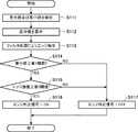
エッジ検出部704には、上述のように、スキャナ部110による原稿の読み取りによって得られた画像データ(画素信号Dg)が入力される。S111で、エッジ検出部704(最大値検出部751及び最小値検出部752)は、入力された画像データにおける、複数の画素を含む所定サイズの領域内の画素値のうちで、最大値及び最小値を検出する。次にS112で、エッジ検出部704(差分算出部753)は、S111で検出された最大値と最小値との差分を算出して差分値を生成する。   As described above, the image data (pixel signal Dg) obtained by reading the document by the scanner unit 110 is input to the edge detection unit 704. In step S111, the edge detection unit 704 (maximum value detection unit 751 and minimum value detection unit 752) has a maximum value and a minimum value among pixel values in a predetermined size area including a plurality of pixels in the input image data. Detect value. In step S112, the edge detection unit 704 (difference calculation unit 753) calculates a difference between the maximum value and the minimum value detected in step S111 and generates a difference value.

S111及びS112の処理の後、S113で、エッジ検出部704(エッジ抽出部754)は、エッジを抽出するためのフィルタ処理を、入力された画像データに対して行うことで、エッジ強度を示すエッジ強度信号の生成(エッジの抽出)を行う。このフィルタ処理では、上述のように、原稿の画像に含まれる網点に対応する周波数成分を強調する、図9に示すような周波数特性を有するフィルタが用いられる。なお、S113の処理は、S111及びS112の処理と並行して行われてもよい。   After the processing of S111 and S112, in S113, the edge detection unit 704 (edge extraction unit 754) performs edge filtering on the input image data by performing filter processing for extracting an edge. Intensity signal generation (edge extraction) is performed. In this filter processing, as described above, a filter having frequency characteristics as shown in FIG. 9 is used to emphasize frequency components corresponding to halftone dots included in the original image. Note that the process of S113 may be performed in parallel with the processes of S111 and S112.

その後、S114で、エッジ検出部704(判定部755)は、S112で算出された差分値が所定の閾値(第1閾値)以上であるか否かを判定する。エッジ検出部704は、差分値が閾値以上である場合にはS115へ処理を進める。S115で、エッジ検出部704(判定部755)は、S113で生成されたエッジ強度信号に基づいてエッジ検出を行う。ここでは、エッジ検出部704(判定部755)は、S113で生成されたエッジ強度信号が示すエッジ強度が所定の閾値(第2閾値)以上であるか否かを判定することで、注目画素がエッジ画素であるか否かを判定する。エッジ検出部704は、エッジ強度が閾値以上である場合にはS116へ、エッジ強度が閾値未満である場合にはS117へ処理を進める。   Thereafter, in S114, the edge detection unit 704 (determination unit 755) determines whether or not the difference value calculated in S112 is greater than or equal to a predetermined threshold (first threshold). If the difference value is greater than or equal to the threshold value, the edge detection unit 704 advances the process to S115. In S115, the edge detection unit 704 (determination unit 755) performs edge detection based on the edge intensity signal generated in S113. Here, the edge detection unit 704 (determination unit 755) determines whether or not the pixel of interest is the edge intensity indicated by the edge intensity signal generated in S113 is greater than or equal to a predetermined threshold (second threshold). It is determined whether the pixel is an edge pixel. The edge detection unit 704 advances the processing to S116 when the edge strength is greater than or equal to the threshold, and advances to S117 when the edge strength is less than the threshold.

S116では、エッジ検出部704(判定部755)は、注目画素がエッジ画素であることを示す、「ON」に設定されたエッジ判定信号を生成して処理を終了する。一方、S117では、エッジ検出部704(判定部755)は、注目画素がエッジ画素ではないことを示す、「OFF」に設定されたエッジ判定信号を生成して処理を終了する。   In S116, the edge detection unit 704 (determination unit 755) generates an edge determination signal set to “ON” indicating that the target pixel is an edge pixel, and ends the processing. On the other hand, in S117, the edge detection unit 704 (determination unit 755) generates an edge determination signal set to “OFF” indicating that the pixel of interest is not an edge pixel, and ends the processing.

一方、S114で、エッジ検出部704(判定部755)は、差分値が閾値未満である場合にはS117へ処理を進める。この場合、エッジ検出部704は、S113で生成されたエッジ強度信号に基づくエッジ検出を無効にする。具体的には、エッジ検出部704は、エッジ強度信号にかかわらず、S117で、注目画素がエッジ画素ではないことを示す、「OFF」に設定されたエッジ判定信号を生成して処理を終了する。   On the other hand, in S114, the edge detection unit 704 (determination unit 755) advances the process to S117 when the difference value is less than the threshold value. In this case, the edge detection unit 704 invalidates edge detection based on the edge intensity signal generated in S113. Specifically, the edge detection unit 704 generates an edge determination signal set to “OFF” indicating that the pixel of interest is not an edge pixel in S117 regardless of the edge strength signal, and ends the processing. .

エッジ検出部704は、図11に示すエッジ検出処理を実行することで、エッジの検出結果として、エッジ判定信号を生成して出力する。空白ページ判定処理部504は、エッジ検出部704によるエッジの検出結果に基づいて、スキャナ部110による読み取りの対象となった対象原稿が空白ページであるか否かを判定する処理を行う。   The edge detection unit 704 generates and outputs an edge determination signal as an edge detection result by executing the edge detection process shown in FIG. The blank page determination processing unit 504 performs processing for determining whether or not the target document read by the scanner unit 110 is a blank page based on the edge detection result by the edge detection unit 704.

なお、本実施形態では、図5〜図9を用いて説明したように、対象原稿が空白ページであるか否かの判定を、エッジ検出部704によるエッジの検出結果から得られるエッジ情報720だけでなく、ヒストグラムセット710にも基づいて行っている。これにより、空白ページの判定精度をより高めることが可能である。   In the present embodiment, as described with reference to FIGS. 5 to 9, whether or not the target document is a blank page is determined only by the edge information 720 obtained from the edge detection result by the edge detection unit 704. Not based on the histogram set 710. Thereby, it is possible to further improve the determination accuracy of the blank page.

以上説明したように、本実施形態では、空白ページ判定処理部504内のエッジ検出部704は、スキャナ部110による原稿の読み取りによって得られた画像データに対して、エッジを抽出するためのフィルタ処理を行うことで、エッジ強度信号を生成する。空白ページ判定処理部504は、エッジ検出部704によるエッジの検出結果に基づいて、スキャナ部110による読み取りの対象となった対象原稿が空白ページであるか否かを判定する。エッジ検出部704は、画像データにおける所定サイズの領域内の画素値のうちで、最大値及び最小値を検出し、それらの差分が第1閾値未満であれば、エッジ強度信号に基づくエッジ検出を無効にする。   As described above, in the present embodiment, the edge detection unit 704 in the blank page determination processing unit 504 performs the filtering process for extracting the edge of the image data obtained by reading the document by the scanner unit 110. To generate an edge strength signal. The blank page determination processing unit 504 determines whether or not the target document read by the scanner unit 110 is a blank page based on the edge detection result by the edge detection unit 704. The edge detection unit 704 detects the maximum value and the minimum value among the pixel values in a region of a predetermined size in the image data, and performs edge detection based on the edge intensity signal if the difference between them is less than the first threshold value. To disable.

このように、低周波及び高周波の周波数成分を有するノイズに起因したエッジの誤検出を、画像データに対するフィルタ処理によって抑制しながら、裏写りによるノイズに起因したエッジの誤検出を抑制することが可能になる。その結果、エッジの誤検出に起因して空白ページ判定部504による空白ページの判定精度が低下することを防止でき、空白ページの判定精度をより高めることが可能である。   In this way, false detection of edges caused by noise due to show-through can be suppressed while suppressing false detection of edges caused by noise having low-frequency and high-frequency frequency components by filtering the image data. become. As a result, it is possible to prevent the blank page determination accuracy by the blank page determination unit 504 from being lowered due to erroneous edge detection, and it is possible to further increase the blank page determination accuracy.

なお、本実施形態で説明したスキャナ画像処理部309による画像処理は、スキャナ等の画像読取装置から提供された画像データに対して画像処理を実行可能なPC等の情報処理装置(画像処理装置)において実行することも可能である。   The image processing by the scanner image processing unit 309 described in the present embodiment is an information processing apparatus (image processing apparatus) such as a PC that can perform image processing on image data provided from an image reading apparatus such as a scanner. It is also possible to execute in

[第2の実施形態]
第1実施形態では、原稿を読み取って得られた画像データに対するフィルタ処理で得られるエッジ強度に基づいてエッジ検出を行うか否かを、S114の判定結果に従って制御することで、原稿画像の裏写りに起因するエッジの誤検出を抑制している。ここで、原稿画像の裏写りに起因して読取結果に生じるノイズは、原稿の用紙種別に依存して異なる特性を示す。このため、S114の判定で用いられる閾値(第1閾値)として固定値を使用した場合、原稿の用紙種別によっては、裏写りに起因するノイズがエッジ検出に与える影響を適切に抑えることができない可能性がある。
[Second Embodiment]
In the first embodiment, the document image show-through is performed by controlling whether or not to perform edge detection based on the edge strength obtained by the filtering process on the image data obtained by reading the document according to the determination result of S114. The false detection of the edge resulting from the is suppressed. Here, the noise generated in the reading result due to the show-through of the document image shows different characteristics depending on the paper type of the document. For this reason, when a fixed value is used as the threshold value (first threshold value) used in the determination of S114, the influence of noise caused by show-through on edge detection may not be appropriately suppressed depending on the paper type of the document. There is sex.

例えば、裏写りが発生しやすい用紙(薄紙等)が原稿の用紙として使用されている場合には、第1閾値を高くしなければ、裏写りに起因するノイズが発生している領域においてエッジ強度信号に基づくエッジ検出を行ってしまう可能性が高くなる。その結果、エッジの誤検出が発生しやすくなりうる。一方で、裏写りが発生しにくい用紙(厚紙等)が原稿の用紙として使用されている場合には、裏写りに起因したノイズが少なくなる。このため、例えば薄紙を基準として第1閾値を設定すると、裏写りが発生していない領域においてエッジ強度信号に基づくエッジ検出を行わない可能性が高くなる。その結果、印刷情報を検出しにくくなりうる。   For example, when a paper (thin paper, etc.) that is likely to show through is used as a document paper, the edge strength is increased in a region where noise due to the show-through occurs unless the first threshold is increased. The possibility of performing edge detection based on the signal increases. As a result, erroneous detection of edges can easily occur. On the other hand, when paper (thick paper or the like) in which show-through hardly occurs is used as a document sheet, noise due to show-through is reduced. For this reason, for example, if the first threshold value is set based on thin paper, there is a high possibility that edge detection based on the edge intensity signal is not performed in a region where no show-through occurs. As a result, it may be difficult to detect print information.

第2の実施形態では、エッジ検出部704によるS114の判定で用いる第1閾値を、原稿の用紙種別に合わせて設定(変更)することで、エッジの誤検出をより適切に抑制し、空白ページの判定精度を高めることを可能にする。以下では、第1の実施形態との相違点を中心として本実施形態について説明する。   In the second embodiment, by setting (changing) the first threshold value used in the determination of S114 by the edge detection unit 704 in accordance with the paper type of the document, erroneous detection of edges is more appropriately suppressed, and a blank page is set. It is possible to improve the accuracy of determination. In the following, the present embodiment will be described focusing on the differences from the first embodiment.

図12は、用紙種別の設定画面1200の例を示す図である。OKボタン1201は、設定画面1200における設定内容を示す設定値を保存して当該画面を閉じることを指示するために用いられる。キャンセルボタン1202は、設定画面1200における設定内容を無効化して当該画面を閉じることを指示するために用いられる。設定ボタン1203〜1205は、原稿の用紙種別を設定するためのボタンであり、それぞれ普通紙、厚紙及び薄紙に対応している。設定ボタン1203〜1205のいずれかが押下されてOKボタン1201が押下されると、CPU301は、設定ボタン1203〜1205のうちで押下されたボタンに対応する種別を原稿の用紙種別として設定する。CPU301は、設定した用紙種別を示す設定値をRAM302またはHDD304に保存する。このようにして、CPU301は、スキャナ部110による読み取りの対象となる原稿の用紙種別を設定する。   FIG. 12 is a diagram illustrating an example of a paper type setting screen 1200. An OK button 1201 is used to save a setting value indicating the setting content on the setting screen 1200 and instruct to close the screen. A cancel button 1202 is used to invalidate the setting contents on the setting screen 1200 and instruct to close the screen. Setting buttons 1203 to 1205 are buttons for setting the paper type of the document, and correspond to plain paper, thick paper, and thin paper, respectively. When any of the setting buttons 1203 to 1205 is pressed and the OK button 1201 is pressed, the CPU 301 sets the type corresponding to the pressed button among the setting buttons 1203 to 1205 as the paper type of the document. The CPU 301 stores a setting value indicating the set paper type in the RAM 302 or the HDD 304. In this way, the CPU 301 sets the paper type of the document to be read by the scanner unit 110.

図10(B)は、本実施形態に係る複写機において実行される複写処理の手順を示すフローチャートである。図10(B)に示す各ステップの処理は、HDD304に格納されたプログラムをCPU301が読み出して実行することによって複写機において実現される。なお、S101〜S105の処理は、第1の実施形態(図10(A))と同様である。S101で、CPU301は、操作部120のスタートキー402の押下が検知されたか否かを判定し、スタートキー402の押下が検知されると、処理をS201へ進める。   FIG. 10B is a flowchart showing a copy processing procedure executed in the copying machine according to the present embodiment. The processing in each step shown in FIG. 10B is realized in the copying machine by the CPU 301 reading and executing the program stored in the HDD 304. Note that the processing of S101 to S105 is the same as that of the first embodiment (FIG. 10A). In step S <b> 101, the CPU 301 determines whether or not pressing of the start key 402 of the operation unit 120 is detected. If pressing of the start key 402 is detected, the process proceeds to step S <b> 201.

S201で、CPU301は、設定画面1200において設定された用紙種別の設定値を取得する。更に、S202で、CPU301は、取得した設定値に従って、判定部755による差分値に基づく判定処理に用いられる閾値(S114において用いられる第1閾値)を設定する。即ち、CPU301は、読み取りの対象となる原稿の用紙種別として設定された用紙種別に従って第1閾値を設定する。   In step S <b> 201, the CPU 301 acquires a set value of the paper type set on the setting screen 1200. Furthermore, in S202, the CPU 301 sets a threshold value (first threshold value used in S114) used in the determination process based on the difference value by the determination unit 755 according to the acquired setting value. That is, the CPU 301 sets the first threshold according to the paper type set as the paper type of the document to be read.

S202では、例えば、普通紙よりも厚い厚紙が原稿の用紙種別として設定されている場合、普通紙が設定されている場合に用いる閾値(普通紙に対応する閾値)よりも低い値を第1閾値として設定する。一方、普通紙よりも薄い薄紙が原稿の用紙種別として設定されている場合、普通紙が設定されている場合に用いる閾値(普通紙に対応する閾値)よりも高い値を第1閾値として設定する。CPU301は、設定した閾値を制御用パラメータとしてスキャナ画像処理部309用のレジスタに書き込むことで、当該閾値をスキャナ画像処理部309に使用させる。なお、CPU301は、読み取りの対象となる原稿の用紙種別として設定された用紙種別の用紙の厚さが大きいほど低い値を第1閾値として設定してもよい。   In S202, for example, when thick paper thicker than plain paper is set as the document paper type, the first threshold is set to a value lower than a threshold (threshold corresponding to plain paper) used when plain paper is set. Set as. On the other hand, when thin paper thinner than plain paper is set as the original paper type, a value higher than the threshold (threshold corresponding to plain paper) used when plain paper is set is set as the first threshold. . The CPU 301 causes the scanner image processing unit 309 to use the threshold value by writing the set threshold value as a control parameter in the register for the scanner image processing unit 309. Note that the CPU 301 may set a lower value as the first threshold value as the paper thickness of the paper type set as the paper type of the document to be read is larger.

S202における閾値の設定が完了すると、CPU301は、処理をS102に進めて原稿の複写処理を開始する。S102〜S105の処理については、第1の実施形態における処理と同様であるので説明を省略する。   When the setting of the threshold value in S202 is completed, the CPU 301 advances the process to S102 and starts the document copying process. Since the processing of S102 to S105 is the same as the processing in the first embodiment, description thereof is omitted.

以上説明したように、本実施形態によれば、原稿画像の裏写りに起因して原稿の読取結果(画像データ)に生じるノイズの量が、原稿の用紙種別に依存して変化しても、S114の判定で用いる閾値を適切に設定することが可能である。これにより、裏写りに起因するノイズによるエッジの誤検出をより適切に抑制し、空白ページの判定精度を高めることを可能にする。   As described above, according to the present embodiment, even if the amount of noise generated in the reading result (image data) of the document due to the show-through of the document image changes depending on the paper type of the document, It is possible to appropriately set the threshold used in the determination of S114. As a result, it is possible to more appropriately suppress erroneous detection of edges due to noise caused by show-through and increase blank page determination accuracy.

[その他の実施形態]
本発明は、上述の実施形態の1以上の機能を実現するプログラムを、ネットワーク又は記憶媒体を介してシステム又は装置に供給し、そのシステム又は装置のコンピュータにおける1つ以上のプロセッサーがプログラムを読出し実行する処理でも実現可能である。また、1以上の機能を実現する回路(例えば、ASIC)によっても実現可能である。
[Other Embodiments]
The present invention supplies a program that realizes one or more functions of the above-described embodiments to a system or apparatus via a network or a storage medium, and one or more processors in a computer of the system or apparatus read and execute the program This process can be realized. It can also be realized by a circuit (for example, ASIC) that realizes one or more functions.

100:プリンタ部、110:スキャナ部、111:原稿フィーダ、120:操作部、301:CPU、309:スキャナ画像処理部、504:空白ページ判定処理部、601:領域制御部、604:エッジ情報生成部、704:エッジ検出部、751:最大値検出部、752:最小値検出部、753:差分算出部、754:エッジ抽出部、755:判定部 100: Printer unit, 110: Scanner unit, 111: Document feeder, 120: Operation unit, 301: CPU, 309: Scanner image processing unit, 504: Blank page determination processing unit, 601: Area control unit, 604: Edge information generation , 704: edge detection unit, 751: maximum value detection unit, 752: minimum value detection unit, 753: difference calculation unit, 754: edge extraction unit, 755: determination unit

Claims (16)

原稿の読み取りによって得られた画像データにおける、複数の画素を含む所定サイズの領域内の画素値のうちで、最大値及び最小値を検出する検出手段と、
エッジを抽出するためのフィルタ処理を前記画像データに対して行うことで、エッジ強度を示す強度信号を生成するフィルタ処理手段と、
前記フィルタ処理手段によって生成された強度信号に基づいてエッジ検出を行うエッジ検出手段であって、前記最大値と前記最小値との差分が第1閾値未満であれば、前記強度信号に基づく前記エッジ検出を無効にする、前記エッジ検出手段と、
前記エッジ検出手段によるエッジの検出結果に基づいて、前記読み取りの対象となった対象原稿が空白ページであるか否かを判定する第1判定手段と、
を備えることを特徴とする画像処理装置。
Detecting means for detecting a maximum value and a minimum value among pixel values in an area of a predetermined size including a plurality of pixels in image data obtained by reading a document;
Filter processing means for generating an intensity signal indicating edge intensity by performing filter processing for extracting an edge on the image data;
Edge detection means for performing edge detection based on the intensity signal generated by the filter processing means, and if the difference between the maximum value and the minimum value is less than a first threshold, the edge based on the intensity signal The edge detection means for disabling detection; and
First determination means for determining whether or not the target document to be read is a blank page based on an edge detection result by the edge detection means;
An image processing apparatus comprising:
前記エッジ検出手段は、前記強度信号に基づいて、注目画素がエッジ画素であるか否かを判定し、前記注目画素がエッジ画素であるか否かを示すエッジ判定信号を生成し、
前記エッジ検出手段は、前記差分が前記第1閾値未満であれば、前記強度信号にかかわらず、前記注目画素がエッジ画素ではないことを示すエッジ判定信号を生成する
ことを特徴とする請求項1に記載の画像処理装置。
The edge detection unit determines whether the target pixel is an edge pixel based on the intensity signal, and generates an edge determination signal indicating whether the target pixel is an edge pixel,
The edge detection means generates an edge determination signal indicating that the pixel of interest is not an edge pixel regardless of the intensity signal if the difference is less than the first threshold value. An image processing apparatus according to 1.
前記エッジ検出手段は、前記強度信号が示すエッジ強度が第2閾値以上であれば、前記注目画素がエッジ画素であると判定し、前記強度信号が示すエッジ強度が前記第2閾値未満であれば、前記注目画素がエッジ画素ではないと判定する
ことを特徴とする請求項2に記載の画像処理装置。
The edge detection means determines that the pixel of interest is an edge pixel if the edge intensity indicated by the intensity signal is greater than or equal to a second threshold, and if the edge intensity indicated by the intensity signal is less than the second threshold. The image processing apparatus according to claim 2, wherein the target pixel is determined not to be an edge pixel.
前記フィルタ処理手段は、原稿の画像に含まれる網点に対応する周波数成分を強調する周波数特性を有するフィルタを用いて、前記画像データに対して前記フィルタ処理を行う
ことを特徴とする請求項1から3のいずれか1項に記載の画像処理装置。
The filter processing means performs the filter processing on the image data using a filter having a frequency characteristic that emphasizes a frequency component corresponding to a halftone dot included in an image of a document. 4. The image processing device according to any one of items 1 to 3.
前記第1閾値は、原稿の画像の裏写りに起因して前記画像データに生じるノイズの振幅に基づいて予め定められる
ことを特徴とする請求項1から4のいずれか1項に記載の画像処理装置。
5. The image processing according to claim 1, wherein the first threshold value is determined in advance based on an amplitude of noise generated in the image data due to a show-through of an image of a document. apparatus.
前記読み取りの対象となる原稿の用紙種別を設定する第1設定手段と、
前記第1設定手段によって設定された用紙種別に従って前記第1閾値を設定する第2設定手段と、を更に備える
ことを特徴とする請求項1から5のいずれか1項に記載の画像処理装置。
First setting means for setting a paper type of the document to be read;
6. The image processing apparatus according to claim 1, further comprising: a second setting unit configured to set the first threshold according to a paper type set by the first setting unit.
前記第2設定手段は、前記設定された用紙種別の用紙の厚さが大きいほど低い値を前記第1閾値として設定する
ことを特徴とする請求項6に記載の画像処理装置。
The image processing apparatus according to claim 6, wherein the second setting unit sets a lower value as the first threshold value as the thickness of the set sheet type is larger.
前記第2設定手段は、
前記設定された用紙種別が普通紙よりも薄い用紙種別であれば、前記普通紙に対応する閾値よりも低い値を前記第1閾値として設定し、
前記設定された用紙種別が前記普通紙よりも厚い用紙種別であれば、前記普通紙に対応する閾値よりも高い値を前記第1閾値として設定する
ことを特徴とする請求項6または7に記載の画像処理装置。
The second setting means includes
If the set paper type is a paper type thinner than plain paper, a value lower than the threshold value corresponding to the plain paper is set as the first threshold value.
8. If the set paper type is thicker than the plain paper, a value higher than a threshold corresponding to the plain paper is set as the first threshold. Image processing apparatus.
前記画像データに基づいて、原稿の領域を分割して得られる複数の分割領域のそれぞれについて、画素値の度数分布を示すヒストグラムを生成する第1生成手段と、
前記エッジ検出手段によるエッジの検出結果に基づいて、前記複数の分割領域のそれぞれのエッジ数を示すエッジ情報を生成する第2生成手段と、を更に備え、
前記第1判定手段は、前記ヒストグラム及び前記エッジ情報に基づいて、前記対象原稿が空白ページであるか否かを判定する
ことを特徴とする請求項1から8のいずれか1項に記載の画像処理装置。
First generating means for generating a histogram indicating a frequency distribution of pixel values for each of a plurality of divided areas obtained by dividing a document area based on the image data;
Second generation means for generating edge information indicating the number of edges of each of the plurality of divided regions based on an edge detection result by the edge detection means;
The image according to any one of claims 1 to 8, wherein the first determination unit determines whether or not the target document is a blank page based on the histogram and the edge information. Processing equipment.
前記複数の分割領域のそれぞれの前記ヒストグラムに基づいて、前記対象原稿が空白ページであるか否かを判定する第2判定手段と、
前記複数の分割領域のそれぞれの前記エッジ数に基づいて、前記対象原稿が空白ページであるか否かを判定する第3判定手段と、を更に備え、
前記第1判定手段は、
前記第2判定手段及び前記第3判定手段の両方が、前記対象原稿が空白ページであると判定した場合には、前記対象原稿が空白ページであることを示す情報を出力し、
前記第2判定手段及び前記第3判定手段の少なくともいずれかが、前記対象原稿が空白ページではないと判定した場合には、前記対象原稿が空白ページではないことを示す情報を出力する
ことを特徴とする請求項9に記載の画像処理装置。
Second determination means for determining whether the target document is a blank page based on the histogram of each of the plurality of divided regions;
A third determination unit that determines whether or not the target document is a blank page based on the number of edges of each of the plurality of divided regions;
The first determination means includes
When both the second determination unit and the third determination unit determine that the target document is a blank page, information indicating that the target document is a blank page is output;
When at least one of the second determination unit and the third determination unit determines that the target document is not a blank page, information indicating that the target document is not a blank page is output. The image processing apparatus according to claim 9.
前記第2判定手段は、前記複数の分割領域のそれぞれの前記ヒストグラムに基づいて、前記複数の分割領域のそれぞれにおける画素値の平均値及び分散値を算出し、当該算出した平均値及び分散値に基づいて、各分割領域が空白領域であるか否かの判定を行い、当該判定の結果に基づいて、前記対象原稿が空白ページであるか否かを判定する
ことを特徴とする請求項10に記載の画像処理装置。
The second determination unit calculates an average value and a variance value of pixel values in each of the plurality of divided regions based on the histogram of each of the plurality of divided regions, and calculates the calculated average value and variance value. 11. The method according to claim 10, further comprising: determining whether each divided area is a blank area based on the determination result, and determining whether the target document is a blank page based on a result of the determination. The image processing apparatus described.
前記第3判定手段は、前記複数の分割領域のそれぞれの前記エッジ数のうちで最大エッジ数及び最小エッジ数を検出し、前記最大エッジ数に基づく第1判定処理と、前記最小エッジ数に基づく第2判定処理と、前記最大エッジ数と前記最小エッジ数との相関値に基づく第3判定処理とを行い、前記第1判定処理、前記第2判定処理、及び前記第3判定処理の結果に基づいて、前記対象原稿が空白ページであるか否かを判定する
ことを特徴とする請求項10または11に記載の画像処理装置。
The third determination means detects the maximum number of edges and the minimum number of edges among the number of edges of each of the plurality of divided regions, and based on the first determination process based on the maximum number of edges and the minimum number of edges A second determination process and a third determination process based on a correlation value between the maximum edge number and the minimum edge number are performed, and the results of the first determination process, the second determination process, and the third determination process are obtained. The image processing apparatus according to claim 10, wherein the image processing apparatus determines whether the target document is a blank page based on the determination.
複数ページの原稿を1枚ずつ搬送する原稿搬送手段と、
前記原稿搬送手段によって1枚ずつ搬送される原稿の画像を順に読み取って、前記複数ページに対応する画像データを生成する読取手段と、
前記読取手段によって生成された前記複数ページに対応する画像データから、前記第1判定手段によって空白ページであると判定された原稿に対応する画像データを削除する削除処理を行う削除手段と、
前記削除処理後の前記複数ページに対応する画像データに基づいて印刷処理を行う印刷手段と、を更に備える
ことを特徴とする請求項1から12のいずれか1項に記載の画像処理装置。
Document conveying means for conveying a plurality of pages of documents one by one;
Reading means for sequentially reading images of originals conveyed one by one by the original conveying means to generate image data corresponding to the plurality of pages;
A deletion unit that performs a deletion process of deleting image data corresponding to a document that has been determined to be a blank page by the first determination unit from image data corresponding to the plurality of pages generated by the reading unit;
The image processing apparatus according to claim 1, further comprising: a printing unit that performs a printing process based on image data corresponding to the plurality of pages after the deletion process.
複数ページの原稿を1枚ずつ搬送する原稿搬送手段と、
前記原稿搬送手段によって1枚ずつ搬送される原稿の画像を順に読み取って、前記複数ページに対応する画像データを生成する読取手段と、
前記読取手段によって生成された前記複数ページに対応する画像データから、前記第1判定手段によって空白ページであると判定された原稿に対応する画像データを削除する削除処理を行う削除手段と、
前記削除処理後の前記複数ページに対応する画像データを、ネットワークを介して外部装置へ送信する送信手段と、を更に備える
ことを特徴とする請求項1から12のいずれか1項に記載の画像処理装置。
Document conveying means for conveying a plurality of pages of documents one by one;
Reading means for sequentially reading images of originals conveyed one by one by the original conveying means to generate image data corresponding to the plurality of pages;
A deletion unit that performs a deletion process of deleting image data corresponding to a document that has been determined to be a blank page by the first determination unit from image data corresponding to the plurality of pages generated by the reading unit;
The image according to any one of claims 1 to 12, further comprising transmission means for transmitting image data corresponding to the plurality of pages after the deletion process to an external device via a network. Processing equipment.
原稿の読み取りによって得られた画像データにおける、複数の画素を含む所定サイズの領域内の画素値のうちで、最大値及び最小値を検出する検出工程と、
エッジを抽出するためのフィルタ処理を前記画像データに対して行うことで、エッジ強度を示す強度信号を生成するフィルタ処理工程と、
前記フィルタ処理工程で生成された強度信号に基づいてエッジ検出を行うエッジ検出工程であって、前記最大値と前記最小値との差分が閾値未満であれば、前記強度信号に基づく前記エッジ検出を無効にする、前記エッジ検出工程と、
前記エッジ検出工程におけるエッジの検出結果に基づいて、前記読み取りの対象となった対象原稿が空白ページであるか否かを判定する判定工程と、
を含むことを特徴とする画像処理方法。
A detection step of detecting a maximum value and a minimum value among pixel values in a region of a predetermined size including a plurality of pixels in image data obtained by reading a document;
A filtering process for generating an intensity signal indicating an edge intensity by performing filtering on the image data to extract an edge;
An edge detection step of performing edge detection based on the intensity signal generated in the filter processing step, and if the difference between the maximum value and the minimum value is less than a threshold value, the edge detection based on the intensity signal is performed. Invalidating the edge detection step;
A determination step of determining whether or not the target document to be read is a blank page, based on an edge detection result in the edge detection step;
An image processing method comprising:
請求項15に記載の画像処理方法の各工程をコンピュータに実行させるためのプログラム。   The program for making a computer perform each process of the image processing method of Claim 15.
JP2016087386A 2016-04-25 2016-04-25 Image processing apparatus, image processing method and program Pending JP2017199976A (en)

Priority Applications (1)

Application Number Priority Date Filing Date Title
JP2016087386A JP2017199976A (en) 2016-04-25 2016-04-25 Image processing apparatus, image processing method and program

Applications Claiming Priority (1)

Application Number Priority Date Filing Date Title
JP2016087386A JP2017199976A (en) 2016-04-25 2016-04-25 Image processing apparatus, image processing method and program

Publications (1)

Publication Number Publication Date
JP2017199976A true JP2017199976A (en) 2017-11-02

Family

ID=60238283

Family Applications (1)

Application Number Title Priority Date Filing Date
JP2016087386A Pending JP2017199976A (en) 2016-04-25 2016-04-25 Image processing apparatus, image processing method and program

Country Status (1)

Country Link
JP (1) JP2017199976A (en)

Cited By (1)

* Cited by examiner, † Cited by third party
Publication number Priority date Publication date Assignee Title
JP2019210388A (en) * 2018-06-06 2019-12-12 国立大学法人群馬大学 Process for producing composite material

Cited By (2)

* Cited by examiner, † Cited by third party
Publication number Priority date Publication date Assignee Title
JP2019210388A (en) * 2018-06-06 2019-12-12 国立大学法人群馬大学 Process for producing composite material
JP7044329B2 (en) 2018-06-06 2022-03-30 国立大学法人群馬大学 Method for manufacturing composite materials

Similar Documents

Publication Publication Date Title
JP4610644B2 (en) Image processing apparatus, image forming apparatus, image processing method, image processing program, and computer-readable recording medium
US8854641B2 (en) Control device for controlling image processing system, image forming apparatus, image reading apparatus, control method, and computer-readable recording medium
US8976414B2 (en) Image processing method, image processing apparatus and image forming apparatus including the same, image reading apparatus, and recording medium
US8437047B2 (en) Image processing apparatus, control method, and program
US8665497B2 (en) Image processing apparatus, image processing method and program
US10659621B2 (en) Image processing apparatus, image processing method, and storage medium
US9571693B2 (en) Image processing apparatus, image processing method, and program
US20150070736A1 (en) Image processing apparatus, image processing method, and program
US20140160515A1 (en) Image reading apparatus, method for controlling image reading apparatus, and storage medium
US8824018B2 (en) Image processing apparatus, image forming apparatus, image reading apparatus, image processing method, and recording medium
JP6590991B2 (en) Information processing apparatus, information processing apparatus control method, and program
JP2017199976A (en) Image processing apparatus, image processing method and program
JP2013012898A (en) Image reader and image forming apparatus
JP7391653B2 (en) Image processing device, image processing method, and program
JP5765169B2 (en) Image processing apparatus, image reading apparatus, and image processing program
JP2015023468A (en) Image processing apparatus and image processing method, and program
JP6391348B2 (en) Image processing apparatus, image processing method, and program
US11233922B2 (en) Image processing device having a function of automatically determining whether a document sheet is a color document or black and white document
JP2013009116A (en) Image processor, image reader, image forming apparatus, image processing method, program and recording medium
JP2014236445A (en) Image processing system, image processing method and image reader
JP5988616B2 (en) Image processing apparatus, image forming apparatus, and dirt determination method
JP2022063681A (en) Image reading device and method for controlling image reading device
JP2022179839A (en) Image reading device, image forming apparatus, and transmittance estimation method
JP2012142722A (en) Reading apparatus, control method, and program
JP2016163074A (en) Image processing apparatus and image processing method, program