JP2012190876A - Control board - Google Patents
Control board Download PDFInfo
- Publication number
- JP2012190876A JP2012190876A JP2011051028A JP2011051028A JP2012190876A JP 2012190876 A JP2012190876 A JP 2012190876A JP 2011051028 A JP2011051028 A JP 2011051028A JP 2011051028 A JP2011051028 A JP 2011051028A JP 2012190876 A JP2012190876 A JP 2012190876A
- Authority
- JP
- Japan
- Prior art keywords
- fan
- housing
- control panel
- duct
- amplifier
- Prior art date
- Legal status (The legal status is an assumption and is not a legal conclusion. Google has not performed a legal analysis and makes no representation as to the accuracy of the status listed.)
- Withdrawn
Links
Images
Landscapes
- Cooling Or The Like Of Electrical Apparatus (AREA)
- Patch Boards (AREA)
Abstract
【課題】制御盤内の機器と外気との接触を遮断しつつ筐体の小型化の要求や筐体に内蔵される機器の増加にも対応して十分な放熱、冷却を行うことができる制御盤を提供する。
【解決手段】筐体の天井部3bに熱交換器3を備えるとともに開閉扉の筐体内側にダクト5を備え、熱交換器3に外気を取り込む第1のファン3cと、筐体内の内気を筐体後部を通って熱交換器3へと送る第2のファン7と、熱交換器3を通過した内気を筐体前部へ下向きに送る第3のファン3dとを備え、第3のファン3dの下方にてダクト5に配設されて内気をダクト5内へ吸気する第4のファン5aと、ダクト5の第4のファン5aより下方に配設されてダクト5内から筐体2内へ排気する第5のファン5bをさらに備える。
【選択図】図4Control capable of sufficient heat dissipation and cooling in response to a demand for downsizing of a housing and an increase in devices incorporated in the housing while blocking contact between the equipment in the control panel and outside air. Provide the board.
A heat exchanger 3 is provided on a ceiling portion 3b of a casing, a duct 5 is provided on an inner side of a casing of an opening / closing door, and a first fan 3c for taking outside air into the heat exchanger 3 and the inside air in the casing are discharged. A second fan 7 for sending the heat to the heat exchanger 3 through the rear of the housing, and a third fan 3d for sending the inside air that has passed through the heat exchanger 3 downward to the front of the housing. A fourth fan 5a that is disposed in the duct 5 below 3d and sucks the inside air into the duct 5, and is disposed below the fourth fan 5a of the duct 5 so that the inside of the casing 2 is inside the duct 5 A fifth fan 5b is further provided for exhausting the air.
[Selection] Figure 4
Description
本発明は産業用ロボット等の制御盤に関し、特に発熱の大きい機器を内蔵した制御盤の冷却のための構成に関する。 The present invention relates to a control panel for an industrial robot or the like, and more particularly to a configuration for cooling a control panel containing a device that generates a large amount of heat.
産業用ロボット等の制御盤には、電源部やサーボアンプに使用されているパワー半導体 素子や抵抗器、制御用基板のCPUなど発熱の大きい機器や素子が内蔵されており、これらから発せられる熱を盤外に放出して、盤内の温度上昇を抑制する冷却構造を備えているのが一般的である。
こうした冷却構造においては、制御盤周囲の粉塵等が盤内の電子機器類へ接触することがないよう、熱交換器を用いて外気を電子機器類に直接当てずに放熱することも行われている。
Industrial robots and other control panels contain power semiconductor elements and resistors used in power supplies and servo amplifiers, and devices and elements that generate large amounts of heat, such as CPUs for control boards. It is common to provide a cooling structure that releases the outside of the board and suppresses the temperature rise inside the board.
In such a cooling structure, heat is radiated without directly applying the outside air to the electronic devices using a heat exchanger so that dust around the control panel does not contact the electronic devices in the panel. Yes.
一方で産業用ロボット等の制御盤については、設置面積の縮小のために筐体の小型化や複数のロボットの制御を1台の制御盤でまとめて行うワン・コントローラ化の要求がある。 筐体を小型化すると制御盤全体の放熱面積が減少する上に熱源である内蔵機器が密集することになり、冷却効率が低下する。またワン・コントローラ化によっても、制御盤複数台分の機器が1つの筐体に収納されることで発熱量が増大するため、同様に冷却効率が低下する。
こうした筐体の小型化への要求に対応しつつ放熱を行うための従来技術として特許文献1や特許文献2のようなものがあった。
On the other hand, for control panels such as industrial robots, there is a demand for a one-controller system that reduces the size of the housing and controls a plurality of robots in a single control panel in order to reduce the installation area. When the housing is downsized, the heat radiation area of the entire control panel is reduced, and the built-in devices that are heat sources are densely packed, resulting in a decrease in cooling efficiency. Even with the one-controller configuration, the amount of heat generated is increased by storing devices for a plurality of control panels in a single casing, and cooling efficiency similarly decreases.
As conventional techniques for performing heat dissipation while responding to the demands for downsizing of the casing, there have been
しかしながら特許文献1や特許文献2による従来の制御盤では、隔壁によって筐体内部を上下に区分けする構造となっており、制御盤のドアを閉めた状態では区分けされた空間内でしか空気が循環しない。
筐体が小型化されると、それに伴い区分けされた空間も小さくなるため、発熱量の大きい機器が小さな空間内に設置されることになる。その結果、発熱量に対して放熱が十分に行えずに熱暴走が発生したり、熱によって筐体内部の電子部品の劣化が早まったりするという問題があった。
However, the conventional control panels according to
When the housing is downsized, the space that is divided is reduced accordingly, so that a device with a large amount of heat generation is installed in a small space. As a result, there is a problem that heat runaway occurs due to insufficient heat dissipation with respect to the heat generation amount, and deterioration of electronic components inside the housing is accelerated by heat.
本発明はこのような問題点に鑑みてなされたものであり、制御盤内の機器と外気との接触を遮断しつつ筐体の小型化の要求や筐体に内蔵される機器の増加にも対応して十分な放熱、冷却を行うことができる制御盤を提供することを目的とする。 The present invention has been made in view of such problems, and it is also necessary to reduce the size of the housing while increasing the number of devices built in the housing while blocking the contact between the devices in the control panel and the outside air. Accordingly, an object of the present invention is to provide a control panel that can perform sufficient heat dissipation and cooling.
上記問題を解決するため、本発明は、次のようにしたのである。
請求項1に記載の発明は、電力消費に伴い発熱するアンプを含む機器を格納し、開閉扉を閉じた状態にて略密閉状態となる筐体を備えた制御盤であって、前記筐体の天井部に熱交換器を備えるとともに前記開閉扉の筐体内側にダクトを備え、前記熱交換器に外気を取り込む第1のファンと、前記筐体内の内気を前記筐体後部を通って前記熱交換器へと送る第2のファンと、前記熱交換器を通過した内気を前記筐体前部へ下向きに送る第3のファンとを備え、前記第3のファンの下方にて前記ダクトに配設されて内気を前記ダクト内へ吸気する第4のファンと、前記ダクトの前記第4のファンより下方に配設されて前記ダクト内から筐体内へ排気する第5のファンをさらに備えることを特徴とする。
In order to solve the above problem, the present invention is as follows.
The invention according to
また請求項2に記載の発明は、前記アンプは前記筐体下部に配設され、前記第5のファンは前記アンプの前方に配設されて前記アンプへ向けて排気することを特徴とする。 The invention according to claim 2 is characterized in that the amplifier is disposed in a lower portion of the casing, and the fifth fan is disposed in front of the amplifier and exhausts toward the amplifier.
請求項3に記載の発明は、前記アンプに併設されて前記筐体内とは隔離された空間を備え、前記空間に外気を取り込む第6のファンと、前記空間内の外気を排気する第7のファンを共に前記筐体背面に備えることを特徴とする。 According to a third aspect of the present invention, there is provided a sixth fan that includes a space that is provided alongside the amplifier and is isolated from the inside of the housing, and that takes in outside air into the space and exhausts outside air within the space. Both fans are provided on the rear surface of the housing.
請求項4に記載の発明は、前記第6のファンと前記第7のファンは上下方向に並んで配設され、前記第6のファンは前記第7のファンの下方に配設されることを特徴とする。 According to a fourth aspect of the present invention, the sixth fan and the seventh fan are arranged side by side in the vertical direction, and the sixth fan is arranged below the seventh fan. Features.
請求項5に記載の発明は、前記空間に、前記アンプに取り付けられたヒートシンクと前記アンプの回生抵抗の少なくとも一方を格納することを特徴とする。
The invention according to
請求項6に記載の発明は、前記アンプを複数備え、前記第5のファンは前記複数の各アンプの前方にそれぞれ1個または複数個配設されたことを特徴とする。 According to a sixth aspect of the present invention, a plurality of the amplifiers are provided, and one or a plurality of the fifth fans are arranged in front of the plurality of amplifiers.
請求項7に記載の発明は、前記アンプを複数備え、前記第6のファンと第7のファンは前記複数の各アンプの後方にそれぞれ1個または複数個配設されたことを特徴とする。 A seventh aspect of the invention is characterized in that a plurality of the amplifiers are provided, and one or a plurality of the sixth fans and the seventh fans are respectively arranged behind the plurality of amplifiers.
請求項8に記載の発明は、複数の前記アンプを上下に積み重ねて配設し、前記各アンプに関する前記空間を一体化して前記筐体内と隔離したことを特徴とする。 The invention described in claim 8 is characterized in that a plurality of the amplifiers are stacked one above the other, and the spaces related to the amplifiers are integrated and separated from the inside of the housing.
請求項9に記載の発明は、前記第1乃至第4の各ファンをそれぞれ複数備えたことを特徴とする。 A ninth aspect of the invention is characterized in that a plurality of the first to fourth fans are provided.
請求項10に記載の発明は、前記第1のファンは下方向へ排気するよう配設されたことを特徴とする。 The invention described in claim 10 is characterized in that the first fan is arranged to exhaust downward.
本発明によると、制御盤内の機器を外気から隔離しつつ、放熱性の確保と筐体の小型化とを両立することができる。また複数の制御盤の機器を1つの筐体に収納した場合にも十分な冷却能力を獲得できる。 According to the present invention, it is possible to achieve both ensuring heat dissipation and downsizing the casing while isolating the equipment in the control panel from the outside air. Further, sufficient cooling capacity can be obtained even when a plurality of control panel devices are housed in one housing.
以下、本発明の具体的実施例について、図に基づいて説明する。
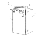
図1はロボット制御盤の全体の外観を示す斜視図である。図示していないが、制御盤はケーブルによってロボットと接続される。ケーブルにはロボットを駆動、制御するための各種電源線、信号線が含まれている。
またロボットの動作プログラムの教示や各種操作、ロボットの状態確認の際に用いる教示装置ともケーブルによって接続可能となっている。図1では教示装置も省略して描いている。
Hereinafter, specific examples of the present invention will be described with reference to the drawings.
FIG. 1 is a perspective view showing the overall appearance of the robot control panel. Although not shown, the control panel is connected to the robot by a cable. The cable includes various power lines and signal lines for driving and controlling the robot.
It can also be connected to a teaching device used for teaching robot operation programs, performing various operations, and checking the status of the robot via a cable. In FIG. 1, the teaching device is also omitted.
制御盤1は、前面部が開口した直方体状の筐体2と、筐体2の上部に設けられた熱交換部3と、筐体2の開口部分を閉じるためのドア4とからなる。
ドア4の側面はヒンジ4aによって筐体開口の側面と連結されることで開閉可能に構成されている。また後述するが、ドア4はその一部に中空構造のダクトを備えるよう構成されている。ドア4は、ドアを閉じた状態でロックするためのハンドル4b、ロボットを非常停止させるための非常停止スイッチなどを備えた操作パネル4cを備える。さらに教示装置を接続するためのコネクタ4dを備える。
ハンドル4bによってドア4をロックすることで筐体内は外気から遮断された状態となる。またハンドル4bは筐体内部のブレーカと連動しており、ハンドルを回してドアをロックした状態でなければブレーカが解除されず制御盤の電源を投入することができないようになっている。
The
The side surface of the
By locking the
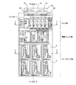
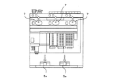
図2はドア4を開放した状態での筐体内部の正面図である。ただし、熱交換部3については説明のために本来であれば見えないファン3c、3dなどが見えるように描いている。
制御盤の内部は、大まかに分けて上下に配置された3つの部位によって構成されている。上部には制御基板が納められたラックがあり、中部には電源ユニット、下部にはロボットに内蔵されたサーボモータを駆動するサーボアンプがそれぞれ収納されている。小型された筐体内であっても出来るだけ内部の熱容量を確保することを狙いとして、各部を区分けするような仕切り板のようなものは設けられていない。また前述のブレーカは作業者がハンドル4bを操作しやすい高さを考慮してラック部に当たる位置に配設されている。
FIG. 2 is a front view of the inside of the housing with the
The interior of the control panel is roughly composed of three parts arranged one above the other. There is a rack containing a control board in the upper part, a power supply unit in the middle part, and a servo amplifier that drives a servo motor built in the robot in the lower part. Even in a small casing, there is no such thing as a partition plate that separates each part with the aim of securing the heat capacity as much as possible. Further, the above-described breaker is disposed at a position where it hits the rack portion in consideration of a height at which an operator can easily operate the
図ではサーボアンプが3台ずつ2段に積み重なるように計6台内蔵されており、各サーボアンプは筐体の奥行き方向に長い略直方体状の形状を有している。近年は筐体の小型化、ワン・コントローラ化の要求に応え、1台で複数台のサーボモータを駆動させることができるサーボアンプが用いられることが多い。本実施例のサーボアンプでは1台につき最大6台のサーボモータを駆動できる。一般的な産業用ロボットは1台につき6つの軸を備えるものが多いので、1つの制御盤で最大6台のロボットを同時に制御することができる。 もちろん複数台のロボットを制御する必要がない場合であればサーボアンプの個数は5以下でもよい。
なお、実際の制御盤では制御基板や電源ユニット、サーボアンプの間を接続するケーブルが配設されているが図ではそうしたケーブル類は省略して描いている。
In the figure, a total of six servo amplifiers are built up so as to be stacked two by three, and each servo amplifier has a substantially rectangular parallelepiped shape that is long in the depth direction of the housing. In recent years, servo amplifiers that can drive a plurality of servo motors by one unit are often used in response to the demands for miniaturization of housings and one-controllers. The servo amplifier of this embodiment can drive a maximum of 6 servo motors per unit. Since many general industrial robots have six axes per unit, a maximum of six robots can be controlled simultaneously with one control panel. Of course, if it is not necessary to control a plurality of robots, the number of servo amplifiers may be 5 or less.
In an actual control panel, cables for connecting the control board, the power supply unit, and the servo amplifier are provided, but such cables are not shown in the drawing.
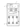
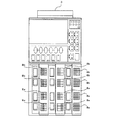
図3はドア4の裏面(筐体側)の正面図である。ドア4は筐体内部側に張り出した中空構造のダクト5を備えており、複数のファンが取り付けられている。ファン5aによって筐体内の空気をダクト5内に吸気し、ファン5bによってダクト5内の空気を筐体内へ排気するようになっている。図3ではファン5aの数は2個となっているがこれは一例であって、1個であったり3個以上であったりしてもよい。
FIG. 3 is a front view of the back surface (housing side) of the
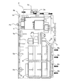
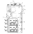
図4は、図2に示した制御盤のA−Aでの側断面図であり、矢印により制御盤内部および熱交換部3の空気の流れを示している。白矢印は筐体内部で循環する内気の流れを示し、黒矢印は筐体外部から取り込まれた外気の流れを示す。
ドアに取り付けられたファン5aはドア4を閉じた状態では電源ユニット部の前方に配置され、ファン5bは各サーボアンプの前方に配置されるようになっている。ファン5aによってドア4内のダクト5の内部へ吸気された電源ユニット部付近の内気は、ダクト5内を通って筐体下部へと流れ、サーボアンプの前面に設けられたファン5bから各サーボアンプ6へと向けて排気される。
なお図3ではファン5bの数は各サーボアンプにつき1個の計6個となっているが、これは一例であって、サーボアンプへの排気を行うファンを各サーボアンプにつき複数個配設してもよい。
ファン5bにより各サーボアンプ6へ吹き付けられた内気はサーボアンプ部の上部かつ筐体の背面近くにあるファン7によって吸気されて筐体の後部を通って上昇し、筐体の天井部3bに達する。
4 is a side cross-sectional view taken along the line AA of the control panel shown in FIG. 2, and the air flow in the control panel and in the heat exchanging unit 3 is indicated by arrows. White arrows indicate the flow of the inside air circulating inside the housing, and black arrows indicate the flow of the outside air taken from the outside of the housing.
The
In FIG. 3, the number of
The inside air blown to each servo amplifier 6 by the
筐体の上面には熱交換部3が設けられている。この熱交換器は筐体の上面に取り付けられたカバー部3aと筐体内の天井部3bから構成される。
外気はファン3cによって筐体の前方から吸気され、後方へ排気される。この外気はカバー部3a内を通過するのみで、筐体内部に流れ込むことはない。ファン3cは横に倒した状態で設置され、吸気した外気を下方へ送る。こうすることでカバー部3aの高さを抑えることができ、制御盤が工場内に設置された際に作業者の視界を遮ってしまうことを防止できる。
一方で筐体内部では、天井部3bに設けられたファン3dによって筐体後方から前方に向けて内気を送り、さらに下方へと送り出している。この天井部3bを通過する内気は、ファン7によって筐体上方へ送られた内気である。
ここで天井部3bの筒部内を通る内気の熱が、カバー部3a内を通過する外気へと移ることで内気が冷却される。
A heat exchange unit 3 is provided on the upper surface of the housing. This heat exchanger includes a
Outside air is sucked from the front of the housing by the
On the other hand, inside the casing, the inside air is sent from the rear to the front of the
Here, the inside air is cooled by the heat of the inside air passing through the inside of the cylindrical portion of the
こうして熱交換により冷却された内気はファン3dによって下方へ送られ、ラック部と電源ユニット部を冷却する。さらにファン5aによって扉のダクト5内へと吸気される。そして前述のようにファン5bによって各サーボアンプ6の前面へ排気され、サーボアンプ6を冷却する。
なお図2ではファン3c、3dの数はそれぞれ2個となっているがこれは一例であって、それぞれ1個であったり3個以上であったりしてもよい。
The inside air thus cooled by heat exchange is sent downward by the
In FIG. 2, the number of
本実施例におけるサーボアンプの冷却についてさらに詳細に説明する。
図2、図4に示したように本実施例ではサーボアンプは3台ずつ上下2段に積まれたように配置されている。
ドア裏面のファン5bは各サーボアンプの前方に計6つ配置され、それぞれサーボアンプへ向けて送風する。さらにサーボアンプ後方上部に配置されたファン7によって吸気することによりサーボアンプから発生する熱を上方へ集め、前述の熱交換部3により冷却を行う。図2に示した制御盤のC−Cでの断面図を図5に示す。図5では、ファン7は3列に配置されたサーボアンプ6に合わせて3つ設けられている。ファン7の数についても適宜変更可能である。
The servo amplifier cooling in this embodiment will be described in more detail.
As shown in FIGS. 2 and 4, in this embodiment, the servo amplifiers are arranged so that three units are stacked in two upper and lower stages.
A total of six
サーボアンプは発熱量が大きいため、内気による冷却に加え、さらに外気による冷却も行っている。各サーボアンプには側面の一方に放熱のためのヒートシンクが取り付けられており、このヒートシンクに外気を当てることにより冷却を行う。また各サーボアンプは回生抵抗を備えていることが一般的でありこれも発熱源となる。本実施例ではヒートシンクに加え、回生抵抗についても外気による冷却を行う。サーボアンプの発熱量が小さく、ファン5bによる冷却で十分な場合にはヒートシンク、回生抵抗のどちらか一方だけを外気で冷却するようにしてもよい。
Since the servo amplifier generates a large amount of heat, it is cooled by outside air in addition to cooling by inside air. Each servo amplifier is provided with a heat sink for heat radiation on one side surface, and cooling is performed by applying outside air to the heat sink. Each servo amplifier generally has a regenerative resistor, which also serves as a heat source. In this embodiment, in addition to the heat sink, the regenerative resistance is also cooled by outside air. When the heat generation amount of the servo amplifier is small and cooling by the
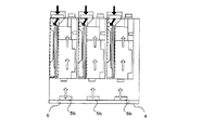
外気によるサーボアンプの冷却について図6〜8を用いて説明する。図6は、図2に示した制御盤のB−Bでの側断面図であり、図7は制御盤の背面図である。また図8は図2に示した制御盤のD−Dでの断面図である。
ヒートシンク6aおよび回生抵抗6bは正面から見て各サーボアンプの左側面にそれぞれ配置されている。また各サーボアンプは筐体内に設けられたラックに対し、前方から引き出し状に格納されるようにして設置されている。
ラックは各列のサーボアンプを仕切るよう構成されており、各サーボアンプをラックに格納することでラックの前面がサーボアンプの前面パネルによって塞がれ、ヒートシンク6aと回生抵抗6bが収納される空間のみがファン8a、8bを介して外気とつながるようになる。
言い換えると、ヒートシンク6aと回生抵抗6bは筐体内部から遮断された空間内に配置され、なおかつ上下に2つ重ねられたサーボアンプの左側面の空間は繋がっている。説明のため、この空間の大まかな配置を図6、図8に破線を用いて示す。上下に積み重ねたサーボアンプのヒートシンクと回生抵抗が収納される空間を連結することでこれらの冷却のための空間を広く取ることができ冷却性能の向上に寄与する。
なお全てのラックにサーボアンプを格納しない場合にはサーボアンプの前面パネルの代わりのパネルでラックを塞ぐことで外気が筐体内に侵入しないようにする。
The cooling of the servo amplifier by the outside air will be described with reference to FIGS. 6 is a side sectional view taken along the line BB of the control panel shown in FIG. 2, and FIG. 7 is a rear view of the control panel. 8 is a cross-sectional view taken along the line DD of the control panel shown in FIG.
The
The rack is configured to partition each row of servo amplifiers. By storing each servo amplifier in the rack, the front surface of the rack is blocked by the front panel of the servo amplifier, and a space in which the
In other words, the
If the servo amplifiers are not stored in all racks, the rack is closed with a panel instead of the front panel of the servo amplifiers so that outside air does not enter the housing.
図7に示すように筐体背面には1つのサーボアンプにつき2個ずつファンが設けられており、これらのうち下段のサーボアンプ用の6つのファンは外気を筐体内部へ吸い込み、上段のサーボアンプ用の6つのファンは筐体内部から外部への排気を行う。
上下に重ねられたサーボアンプのうち、下段のものについてはファン8aによって吸気された外気がヒートシンク6aおよび回生抵抗6bに当たることによって冷却される。下段のヒートシンク6a、回生抵抗6bを通過して熱せられた外気は、サーボアンプ6の前方部へ移動すると共に上昇して上段のサーボアンプ側面の空間へ到達する。
ファン8bは排気を行うのでサーボアンプの前方部から筐体の背面へ向かって空気の流れが発生する。この流れが上段のサーボアンプの前方部から後方にかけてヒートシンク6a、回生抵抗6bに当たって冷却を行い、筐体の外に排出される。
前述のようにヒートシンクと回生抵抗を冷却するための外気は筐体内部とは遮断されているので、外気がサーボアンプ側面の空間以外の筐体内に侵入することがない。
なお図6、7ではファン8a、8bの数はそれぞれ2個となっているがこれは一例であって、それぞれ1個であったり3個以上であったりしてもよい。
As shown in FIG. 7, two fans are provided for each servo amplifier on the back of the chassis. Of these, six fans for the lower servo amplifiers draw outside air into the chassis, and the upper servos. The six fans for the amplifier exhaust from the inside of the housing to the outside.
Of the servo amplifiers stacked vertically, the lower one is cooled by the outside air sucked by the
Since the
As described above, since the outside air for cooling the heat sink and the regenerative resistor is cut off from the inside of the housing, the outside air does not enter into the housing other than the space on the side surface of the servo amplifier.
In FIGS. 6 and 7, the number of
以上説明したように、本実施例によれば外気が筐体内部の機器の接触することなく冷却を行うことができ、工場ラインの雰囲気に含まれる粉塵や油滴、塗料ミスト等が制御盤内の電子機器へ悪影響を与えることがない。
さらに発熱の大きいサーボアンプについては内気と外気の双方により冷却を行うことで十分な廃熱、冷却機能を備え、なおかつ小型の制御盤を提供することが可能となる。
As described above, according to the present embodiment, the outside air can be cooled without contacting the equipment inside the housing, and dust, oil droplets, paint mist, etc. contained in the atmosphere of the factory line are contained in the control panel. The electronic equipment will not be adversely affected.
Furthermore, a servo amplifier with a large heat generation can be provided with a sufficient waste heat and cooling function by cooling with both the inside air and the outside air, and a small control panel can be provided.
1 制御盤
2 筐体
3 熱交換部
3a カバー
3b 天井部
3c 熱交換器用ファン(第1のファン)
3d 熱交換器用ファン(第3のファン)
4 ドア
4a ヒンジ
4b ハンドル
4c 操作パネル
4d コネクタ
5 ダクト
5a ダクト内吸気ファン(第4のファン)
5b ダクト外排気ファン(第5のファン)
6 サーボアンプ
6a ヒートシンク
6b 回生抵抗
7 ファン(第2のファン)
8a 吸気ファン(第6のファン)
8b 排気ファン(第7のファン)
1 Control Panel 2 Housing 3
3d Heat exchanger fan (third fan)
4
5b Exhaust fan outside duct (fifth fan)
6
8a Intake fan (sixth fan)
8b Exhaust fan (seventh fan)
Claims (10)
前記筐体の天井部に熱交換器を備えるとともに前記開閉扉の筐体内側にダクトを備え、
前記熱交換器に外気を取り込む第1のファンと、
前記筐体内の内気を前記筐体後部を通って前記熱交換器へと送る第2のファンと、
前記熱交換器を通過した内気を前記筐体前部へ下向きに送る第3のファンとを備え、
前記第3のファンの下方にて前記ダクトに配設されて内気を前記ダクト内へ吸気する第4のファンと、
前記ダクトの前記第4のファンより下方に配設されて前記ダクト内から筐体内へ排気する第5のファンをさらに備えることを特徴とした制御盤。 A control panel that houses a device including an amplifier that generates heat with power consumption, and has a casing that is substantially sealed when the door is closed,
With a heat exchanger on the ceiling of the casing and a duct on the inside of the casing of the door,
A first fan for taking outside air into the heat exchanger;
A second fan for sending inside air in the housing to the heat exchanger through the rear of the housing;
A third fan that sends the inside air that has passed through the heat exchanger downward to the front of the housing;
A fourth fan disposed in the duct below the third fan and sucking the inside air into the duct;
The control panel further comprising a fifth fan disposed below the fourth fan of the duct and exhausting from the duct into the housing.
Priority Applications (1)
| Application Number | Priority Date | Filing Date | Title |
|---|---|---|---|
| JP2011051028A JP2012190876A (en) | 2011-03-09 | 2011-03-09 | Control board |
Applications Claiming Priority (1)
| Application Number | Priority Date | Filing Date | Title |
|---|---|---|---|
| JP2011051028A JP2012190876A (en) | 2011-03-09 | 2011-03-09 | Control board |
Publications (1)
| Publication Number | Publication Date |
|---|---|
| JP2012190876A true JP2012190876A (en) | 2012-10-04 |
Family
ID=47083756
Family Applications (1)
| Application Number | Title | Priority Date | Filing Date |
|---|---|---|---|
| JP2011051028A Withdrawn JP2012190876A (en) | 2011-03-09 | 2011-03-09 | Control board |
Country Status (1)
| Country | Link |
|---|---|
| JP (1) | JP2012190876A (en) |
Cited By (6)
| Publication number | Priority date | Publication date | Assignee | Title |
|---|---|---|---|---|
| CN106256176A (en) * | 2015-04-03 | 2016-12-21 | 三菱电机株式会社 | Electronic equipment |
| WO2018155689A1 (en) | 2017-02-27 | 2018-08-30 | 川崎重工業株式会社 | Control panel |
| JP2020035737A (en) * | 2018-06-15 | 2020-03-05 | フルークコーポレイションFluke Corporation | Electrical panel adapter providing path-through access to electrical signal within enclosure |
| JP2020057723A (en) * | 2018-10-03 | 2020-04-09 | 川崎重工業株式会社 | Cooling structure and robot control device including the same |
| CN119403076A (en) * | 2024-09-30 | 2025-02-07 | 超聚变数字技术有限公司 | Server node and server |
| WO2026038358A1 (en) * | 2024-08-16 | 2026-02-19 | ファナック株式会社 | Robot control device |
-
2011
- 2011-03-09 JP JP2011051028A patent/JP2012190876A/en not_active Withdrawn
Cited By (15)
| Publication number | Priority date | Publication date | Assignee | Title |
|---|---|---|---|---|
| CN106256176A (en) * | 2015-04-03 | 2016-12-21 | 三菱电机株式会社 | Electronic equipment |
| JP6072985B1 (en) * | 2015-04-03 | 2017-02-01 | 三菱電機株式会社 | Electronics |
| US9795067B2 (en) | 2015-04-03 | 2017-10-17 | Mitsubishi Electric Corporation | Electronic apparatus |
| CN106256176B (en) * | 2015-04-03 | 2017-12-05 | 三菱电机株式会社 | Electronic equipment |
| KR20190107724A (en) | 2017-02-27 | 2019-09-20 | 카와사키 주코교 카부시키 카이샤 | panel |
| JP2018142585A (en) * | 2017-02-27 | 2018-09-13 | 川崎重工業株式会社 | control panel |
| WO2018155689A1 (en) | 2017-02-27 | 2018-08-30 | 川崎重工業株式会社 | Control panel |
| CN110313227A (en) * | 2017-02-27 | 2019-10-08 | 川崎重工业株式会社 | Control panel |
| CN110313227B (en) * | 2017-02-27 | 2020-09-22 | 川崎重工业株式会社 | control panel |
| US11382236B2 (en) | 2017-02-27 | 2022-07-05 | Kawasaki Jukogyo Kabushiki Kaisha | Controller |
| JP2020035737A (en) * | 2018-06-15 | 2020-03-05 | フルークコーポレイションFluke Corporation | Electrical panel adapter providing path-through access to electrical signal within enclosure |
| JP2020057723A (en) * | 2018-10-03 | 2020-04-09 | 川崎重工業株式会社 | Cooling structure and robot control device including the same |
| JP7112304B2 (en) | 2018-10-03 | 2022-08-03 | 川崎重工業株式会社 | COOLING STRUCTURE AND ROBOT CONTROL DEVICE INCLUDING THE SAME |
| WO2026038358A1 (en) * | 2024-08-16 | 2026-02-19 | ファナック株式会社 | Robot control device |
| CN119403076A (en) * | 2024-09-30 | 2025-02-07 | 超聚变数字技术有限公司 | Server node and server |
Similar Documents
| Publication | Publication Date | Title |
|---|---|---|
| US7769489B2 (en) | Robot control device and robot system | |
| CN102016263B (en) | Arrangement structure for power converter and control box in package-housed engine generator | |
| JP6944251B2 (en) | control panel | |
| CN100425918C (en) | Outdoor unit of air conditioner | |
| JP2012190876A (en) | Control board | |
| JP2005019562A (en) | Electronic equipment cooling structure | |
| CN102386571A (en) | Transformer cooling device | |
| JP4800237B2 (en) | Electronic device storage device | |
| JP2001245408A (en) | control panel | |
| JP2005268546A (en) | Enclosure unit storage rack | |
| JP5444513B2 (en) | control panel | |
| KR101859910B1 (en) | Package-stored engine generator | |
| JP2007074865A (en) | Power converter | |
| JP2010118492A (en) | Power control device | |
| CN102468739A (en) | Cooling device of electric conversion device | |
| WO2018061071A1 (en) | Outdoor unit of air conditioner | |
| JP4713458B2 (en) | Electronic device storage device | |
| JP5446547B2 (en) | Robot controller | |
| JP2017147318A (en) | Electrical equipment | |
| JP7552446B2 (en) | Electrical equipment storage panel | |
| JP2004020171A (en) | Cooling device in cabinet for information communication loaded with computer | |
| JP6570293B2 (en) | Panel cooling system | |
| JP5829992B2 (en) | Electrical equipment storage device | |
| JP7278713B2 (en) | laser device | |
| JP4831207B2 (en) | Air conditioner |
Legal Events
| Date | Code | Title | Description |
|---|---|---|---|
| A300 | Withdrawal of application because of no request for examination |
Free format text: JAPANESE INTERMEDIATE CODE: A300 Effective date: 20140513 |