JP2012189280A - Light-condensing device, converging device and lens sheet - Google Patents
Light-condensing device, converging device and lens sheet Download PDFInfo
- Publication number
- JP2012189280A JP2012189280A JP2011054476A JP2011054476A JP2012189280A JP 2012189280 A JP2012189280 A JP 2012189280A JP 2011054476 A JP2011054476 A JP 2011054476A JP 2011054476 A JP2011054476 A JP 2011054476A JP 2012189280 A JP2012189280 A JP 2012189280A
- Authority
- JP
- Japan
- Prior art keywords
- light
- inclined surface
- condensing
- emitted
- optical
- Prior art date
- Legal status (The legal status is an assumption and is not a legal conclusion. Google has not performed a legal analysis and makes no representation as to the accuracy of the status listed.)
- Withdrawn
Links
Images


Classifications
-
- Y—GENERAL TAGGING OF NEW TECHNOLOGICAL DEVELOPMENTS; GENERAL TAGGING OF CROSS-SECTIONAL TECHNOLOGIES SPANNING OVER SEVERAL SECTIONS OF THE IPC; TECHNICAL SUBJECTS COVERED BY FORMER USPC CROSS-REFERENCE ART COLLECTIONS [XRACs] AND DIGESTS
- Y02—TECHNOLOGIES OR APPLICATIONS FOR MITIGATION OR ADAPTATION AGAINST CLIMATE CHANGE
- Y02E—REDUCTION OF GREENHOUSE GAS [GHG] EMISSIONS, RELATED TO ENERGY GENERATION, TRANSMISSION OR DISTRIBUTION
- Y02E10/00—Energy generation through renewable energy sources
- Y02E10/40—Solar thermal energy, e.g. solar towers
Abstract
Description
本発明は、集光装置、集束装置及びレンズシートに関し、さらに詳しくは、太陽光発電や採光装置、光学センサとして利用される集光装置、集束装置及び集光装置に利用されるレンズシートに関する。 The present invention relates to a condensing device, a condensing device, and a lens sheet, and more particularly to a concentrating device used as a solar power generation or lighting device, an optical sensor, a condensing device, and a lens sheet used for the condensing device.
太陽光発電や、屋内に太陽光を取り込む採光システム、光学センサ等に集光装置が利用されている。たとえば、太陽光発電に利用される集光装置は、複数の反射部材と、受光装置とを備える。受光装置は、塔の上部に配置される。複数の反射部材は塔の周りに配置される。反射部材は太陽光を反射して受光装置(レシーバ)に光を集める。レシーバは、反射部材から太陽光を受け、内部に収納される熱媒体(溶融塩等)に熱エネルギを与える。熱エネルギを受けた熱媒体は発電装置に送られ、発電装置は、熱媒体の熱エネルギを利用して発電する。 A condensing device is used for solar power generation, a daylighting system for taking sunlight into the room, an optical sensor, and the like. For example, a light collecting device used for solar power generation includes a plurality of reflecting members and a light receiving device. The light receiving device is arranged at the top of the tower. The plurality of reflecting members are arranged around the tower. The reflecting member reflects sunlight and collects light in the light receiving device (receiver). The receiver receives sunlight from the reflecting member and gives thermal energy to a heat medium (molten salt or the like) housed inside. The heat medium that has received the heat energy is sent to the power generation device, and the power generation device generates power using the heat energy of the heat medium.
採光システムは、国際公開2005/104819号(特許文献1)、特表2010−52582号公報(特許文献2)、特開2000−57820号公報(特許文献3)及び特開平04−190303号公報(特許文献4)に開示されている。採光システムに利用される集光装置は、レンズと、受光装置とを備える。レンズは、太陽光をレンズの焦点に集光して出射する。受光装置は、光伝送ダクトや光ファイバケーブル等である。受光装置は、レンズにより集光された光を受け、屋内等に伝送する。 As for the daylighting system, International Publication No. 2005/104819 (Patent Document 1), Japanese Translation of PCT International Publication No. 2010-52582 (Patent Document 2), Japanese Patent Application Laid-Open No. 2000-57820 (Patent Document 3) and Japanese Patent Application Laid-Open No. 04-190303 ( It is disclosed in Patent Document 4). The light collecting device used in the daylighting system includes a lens and a light receiving device. The lens collects and emits sunlight at the focal point of the lens. The light receiving device is an optical transmission duct, an optical fiber cable, or the like. The light receiving device receives the light collected by the lens and transmits the light indoors.
従来の太陽光発電や採光システム等に利用される集光装置は、上述のとおり、反射部材を用いたり、焦点に集光するレンズを用いたりする。このような集光装置では、太陽光の集光効率が低くなる場合がある。 As described above, a light collecting device used in a conventional solar power generation or daylighting system uses a reflecting member or a lens that focuses light at a focal point. In such a condensing device, the condensing efficiency of sunlight may become low.
本発明の他の目的は、高い集光効率が得られる集光装置を提供することである。 Another object of the present invention is to provide a light collecting device that can obtain high light collecting efficiency.
本発明による集光装置は、集束装置と、受光装置とを備える。集束装置は、平行光源からの光を受け、出射する。受光装置は、集束装置からの出射光を受ける。集束装置は、第1光学シートを備える。第1光学シートは、平行光源と対向する第1表面と、第1表面と反対側に配置され、平行光源からの光を出射する第1構造化面とを有する。第1構造化面は、配列された複数の第1線状プリズムを含む。 The light collecting device according to the present invention includes a focusing device and a light receiving device. The focusing device receives and emits light from the parallel light source. The light receiving device receives light emitted from the focusing device. The focusing device includes a first optical sheet. The first optical sheet has a first surface facing the parallel light source, and a first structured surface that is disposed on the opposite side of the first surface and emits light from the parallel light source. The first structured surface includes a plurality of first linear prisms arranged.
本発明による集光装置は、集光効率を高める。 The light collecting device according to the present invention increases the light collecting efficiency.
好ましくは、集束装置はさらに、第1構造化面と対向する第2光学シートを備える。第2光学シートは、第1構造化面と対向する第2構造化面と、第2構造化面と反対側の第2表面とを備える。第2構造化面は、第1線状プリズムの長手方向に沿って延びる複数の第2線状プリズムを含み、受光装置は、前記第2表面からの前記出射光を受ける。 Preferably, the focusing device further comprises a second optical sheet facing the first structured surface. The second optical sheet includes a second structured surface that faces the first structured surface and a second surface opposite to the second structured surface. The second structured surface includes a plurality of second linear prisms extending along the longitudinal direction of the first linear prism, and the light receiving device receives the emitted light from the second surface.
この場合、集光効率がさらに高まる。 In this case, the light collection efficiency is further increased.
好ましくは、複数の第1及び第2線状プリズムは、中心軸周りに同心円状に配置される。第2表面は、中心軸に向かって光を出射する。集束装置はさらに、第2プリズムシートの第2表面側の中心軸上に配置され、第2表面から離れるに従って幅が狭くなる反射部材を備える。 Preferably, the plurality of first and second linear prisms are arranged concentrically around the central axis. The second surface emits light toward the central axis. The focusing device further includes a reflecting member that is disposed on the central axis on the second surface side of the second prism sheet and that decreases in width as it moves away from the second surface.
この場合、集光効率がさらに高まる。 In this case, the light collection efficiency is further increased.
好ましくは、第1線状プリズムは、主傾斜面と、主傾斜面と背向して配置される補助傾斜面とを有する。第2線状プリズムは、第2補助傾斜面と、第1主傾斜面から出射した光とのなす角度が第2補助傾斜面よりも大きい第2主傾斜面とを有する。第1主傾斜面は中心軸と反対側に傾斜し、第2主傾斜面は中心軸と反対側に傾斜する。 Preferably, the first linear prism has a main inclined surface and an auxiliary inclined surface disposed opposite to the main inclined surface. The second linear prism has a second auxiliary inclined surface and a second main inclined surface having an angle formed by the light emitted from the first main inclined surface that is larger than that of the second auxiliary inclined surface. The first main inclined surface is inclined opposite to the central axis, and the second main inclined surface is inclined opposite to the central axis.
好ましくは、複数の第1線状プリズムは中心軸周りに同心円状に配置され、第1主傾斜面は中心軸と反対側に傾斜し、集束装置はさらに、第1プリズムシートの第1構造化面側に第1線状プリズムと同軸に配置され、第1構造化面から離れるに従って幅が狭くなる円錐状の反射部材を備える。 Preferably, the plurality of first linear prisms are arranged concentrically around the central axis, the first main inclined surface is inclined to the opposite side of the central axis, and the focusing device further includes a first structuring of the first prism sheet. A conical reflecting member is provided on the surface side so as to be coaxial with the first linear prism, and becomes narrower as the distance from the first structured surface increases.
この場合、集光効率がさらに高まる。 In this case, the light collection efficiency is further increased.
好ましくは、第2線状プリズムは、第2補助傾斜面と、第1主傾斜面から出射した光とのなす角度が第2補助傾斜面よりも大きい第2主傾斜面とを有する。 Preferably, the second linear prism has a second auxiliary inclined surface and a second main inclined surface having an angle formed between the second auxiliary inclined surface and light emitted from the first main inclined surface is larger than that of the second auxiliary inclined surface.
以下、図面を参照し、本発明の実施の形態を詳しく説明する。図中同一又は相当部分には同一符号を付してその説明は繰り返さない。 Hereinafter, embodiments of the present invention will be described in detail with reference to the drawings. In the drawings, the same or corresponding parts are denoted by the same reference numerals and description thereof will not be repeated.
[第1の実施の形態]
[集光装置3の全体構成]
図1は、本発明の第1の実施の形態による集光装置の模式図である。図1を参照して、集光装置3は太陽光発電として利用される。集光装置3は、受光装置35と、集束装置30とを備える。集束装置30は、平行光源である太陽1から出射される光S0を受け、光S0を集束して光S1を出射する。受光装置35は、周知のレシーバである。受光装置35は、内部に熱媒体(溶融塩等)が収納される。受光装置35は、光S1を受け、熱媒体に熱エネルギを与える。熱エネルギを受けた熱媒体は発電装置に送られ、発電装置は熱エネルギを利用して発電する。上述の受光装置35はレシーバであるが、受光装置35は、太陽電池であってもよい。
[First Embodiment]
[Entire configuration of the light collecting device 3]
FIG. 1 is a schematic diagram of a light collecting device according to a first embodiment of the present invention. With reference to FIG. 1, the condensing
受光装置35に光S0を集めるため、複数の集束装置30は、受光装置35を中心とした複数の円周状に配置される。
In order to collect the light S0 on the
[集束装置30の構成]
図2は、集束装置30の側面図である。図2を参照して、集束装置30は、光学部材31と、反射部材32,33とを備える。光学部材31は、平行光である太陽光S0を受け、太陽光S0を集束して太陽光S1を出射する。反射部材32及び33は、太陽光S1を反射して受光装置35に導く。反射部材32及び33は、太陽光S1を全反射する。反射部材32及び33の素材は、全反射すれば特に限定されない。図2では、2つの反射部材32及び33を示したが、反射部材は3以上であってもよいし、1つであってもよい。また、反射部材はなくてもよい。この場合、太陽光S1が直接、受光装置35に入射する。たとえば、図2中の反射部材32に変えて、太陽電池からなる受光装置35が配置されてもよい。
[Configuration of Focusing Device 30]
FIG. 2 is a side view of the focusing
集束装置30はさらに、図示しない制御装置を備える。制御装置は、周知の太陽追尾装置を備える。太陽追尾装置は、太陽1を自動追尾する。制御装置は、太陽追尾装置を利用して、光学部材31が平行光S0を常に受光できるように、光学部材31の角度を調整する。制御装置はさらに、反射部材32及び33の配置位置及び角度を調整する。
The focusing
[光学部材31の構成]
図3Aは、光学部材31の平面図である。図3Bは、図3A中の線分B−Bでの断面図である。図3A及び図3Bを参照して、光学部材31は、光学シート311及び315と、反射部材319とを備える。
[Configuration of Optical Member 31]
FIG. 3A is a plan view of the
光学シート311及び315は、互いに上下に重ねて配置される。図3A及び図3Bでは、光学シート311は、光学シート315の上に配置される。
The
光学シート311は、円板状である。光学シート311は、表面312と、構造化面313とを有する。表面312は平坦であり、太陽光S0を受ける。
The
構造化面313は、表面312と反対側に配置される。図3Bに示すとおり、構造化面313は、複数の線状プリズム314を備える。線状プリズム314は、長手方向を有し、横断形状が三角形状である。本例では、線状プリズム314は円環状であり、光学シート311の中心軸C周りに同心円状に配置される。要するに、複数の線状プリズム314は互いに同軸に配置される。構造化面313は、線状プリズム314により太陽光S0を屈折して出射する。
The
光学シート315も光学シート311と同様に円板状であり、構造化面316と表面317とを有する。構造化面316は構造化面313と対向する。構造化面316は、複数の線状プリズム318を備える。線状プリズム318も線状プリズム314と同様に、長手方向を有し、横断形状は三角形状である。複数の線状プリズム318は線状プリズム314と同様に、中心軸C周りに同心円状に配置される。したがって、線状プリズム318は線状プリズム314と対向する。構造化面316は、構造化面313からの出射光を受ける。
The
表面317は、第2構造化面316と反対側に配置される。表面317は、平坦である。表面317は、構造化面316に入射した光を屈折し、外部に出射する。
The
反射部材319は、光学シート315の下に配置される。より具体的には、反射部材319は、表面317側であって、表面317の中央部分に配置される。反射部材319の幅は、表面317から離れるにしたがって徐々に狭くなる。本例では、反射部材319は円錐状である。しかしながら、反射部材319は円錐状に限定されない。たとえば、反射部材319は円錐台状であってもよい。要するに、反射部材319の幅が表面317から離れるにしたがって狭くなればよい。
The
反射部材319は、表面317の出射光を全反射して下方に導く。反射部材319の素材は周知の素材を利用できる。好ましくは高反射率のものを利用するのが好ましい。
The
光学部材31は、光学シート311及び315により、太陽光S0を中心軸C1方向に屈折して出射する。換言すれば、光学シート311及び315は、太陽光S0を中心軸C1方向に集光する。反射部材319は集光された太陽光S0を全反射して、太陽光S1として出射する。図3Bを参照して、光学部材31を利用すれば、幅W0で光学部材31に入射した太陽光S0は、幅W0よりも小さい幅W1の太陽光(平行光)S1として出射される。
The
従来の太陽光発電で利用される反射部材の場合、全反射した太陽光の幅は小さくならない。さらに、反射部材に代えて所定の焦点距離で集光するレンズを利用した場合、レンズから出射する光は平行光ではない。そのため、集光効率が低い。しかしながら、本実施の形態による光学部材31は、平行光である太陽光S0を、さらに小さい幅の平行光S1として出射する。したがって、より多くの太陽光S0を受光装置35に導くことができ、高い集光効率が得られる。
In the case of a reflective member used in conventional solar power generation, the width of the totally reflected sunlight is not reduced. Further, when a lens that condenses light at a predetermined focal length is used instead of the reflecting member, the light emitted from the lens is not parallel light. Therefore, the light collection efficiency is low. However, the
以下、光学シート311及び315の詳細を説明する。
Details of the
[光学シート311の構成]
図4は、図3B中の領域IVの拡大図である。図4を参照して、線状プリズム314は、主傾斜面314Aと、補助傾斜面314Bとを有する。主傾斜面314Aと補助傾斜面314Bとは互いに背向して配置される。主傾斜面314Aと補助傾斜面314Bとの交差した部分が、線状プリズム314の頂上に相当する。
[Configuration of Optical Sheet 311]
FIG. 4 is an enlarged view of a region IV in FIG. 3B. Referring to FIG. 4,
主傾斜面314Aは、表面312に略垂直に入射した光S0を屈折し、外部に出射する。補助傾斜面314Bは、光S0を屈折しない方が好ましい。補助傾斜面314Bで光S0が屈折されれば、主傾斜面314Aの出射光と補助傾斜面314Bの出射光が交差する。そのため、光学シート311の出射光の指向性が低下する可能性がある。好ましくは、補助傾斜面314Bは、表面312に対して90°±5°であり、より好ましくは、90°±2°である。補助傾斜面314Bが表面312に対して90°よりも顕著に小さければ、補助傾斜面314Bにも平行光S0が入射する。主傾斜面314Aの出射光は、補助傾斜面314Bの出射光と交差するため、出射光の指向性が低下し、集光効率が低下する。一方、補助傾斜面314Bが表面312に対して90°よりも顕著に大きければ、主傾斜面314Aから出射した光が、隣の線状プリズム314の補助傾斜面314Bに入射する場合がある。この場合も、出射光の集光指向性が低下する。補助傾斜面314Bが表面312に対して略90°であれば、光S0は補助傾斜面314Bにほとんど入射しない。
The main
主傾斜面314Aは、補助傾斜面314Bよりも中心軸Cから離れて配置される換言すれば、補助傾斜面314Bが中心軸C側に配置される。光学シート311の表面312は、光S0を表面312に対して垂直に入射する。主傾斜面314Aは、中心軸Cと反対側に傾斜する。
The main
太陽1から出射された平行光S0が、表面312に入射する。このとき、集束装置30の制御装置は、太陽自動追尾装置を利用して、表面312が光S0に対して常時垂直になるように、光学シート311及び315を配置する。
Parallel light S <b> 0 emitted from the
光学シート311に入射した平行光S0は、図4に示すとおり、光学シート311内を進み、主傾斜面314Aに到達する。このとき、主傾斜面314Aは中心軸Cと反対側に傾斜するため、光S0は中心軸C側に屈折して外部に出射する。一方、補助傾斜面314Bには光S0がほとんど入射しない。補助傾斜面314Bと光S0とがなす角は、主傾斜面314Aよりも小さいためである。図4に示すとおり、補助傾斜面314Bが表面312に対して略垂直である場合、光S0は補助傾斜面314Bにほとんど入射しない。
The parallel light S0 incident on the
図3Aに示すとおり、線状プリズム314は中心軸C周りに同心円状に配置される。したがって、表面312に垂直に入射する平行光S0は、各線状プリズム314の主傾斜面314Aにおいて、中心軸C方向に屈折して出射する。
As shown in FIG. 3A, the
[光学シート315の構成]
図5は、図3中の領域Vの拡大図である。図5を参照して、線状プリズム318は、主傾斜面318Aと、補助傾斜面318Bとを有する。線状プリズム314と同様に、主傾斜面318Aと補助傾斜面318Bとは互いに背向して配置され、線状プリズム318の頂上を形成する。
[Configuration of Optical Sheet 315]
FIG. 5 is an enlarged view of a region V in FIG. Referring to FIG. 5,
主傾斜面314Aの出射光に対する主傾斜面318Aの角度は、補助傾斜面318Bの角度よりも大きい。そのため、線状プリズム318においては主として、主傾斜面318Aが、主傾斜面314Aの出射光を受ける。
The angle of the main
図5に示すとおり、主傾斜面314Aの出射光S0(つまり、光学シート311の出射光)は、主傾斜面318Aに入射する。このとき、主傾斜面314Aは光S0を透過する。光S0はそのまま光学シート315内を進み、表面317に到達する。光S0は表面317で屈折し、中心軸C1側に出射する。
As shown in FIG. 5, the outgoing light S0 from the main
好ましくは、補助傾斜面314Bは、光学シート311の出射光S0と略平行である。具体的には、出射光S0と補助傾斜面318Bとがなす角度は、±5°以内である。この場合、出射光S0は、補助傾斜面318Bにほとんど入射しない。その結果、出射光S0のほとんどは主傾斜面318Aに入射し、中心軸C方向に出射する。そのため、光学シート315の出射光S0の指向性が向上する。
Preferably, the auxiliary
さらに好ましくは、主傾斜面318Aは、出射光S0に対して略垂直である。具体的には、好ましくは、主傾斜面318Aと出射光S0とがなす角は、90°±5°である。要するに、出射光S0は、主傾斜面318Aで屈折しない方が好ましい。出射光S0が屈折する場合、屈折した出射光S0が補助傾斜面318Bに入射し、全反射又は屈折する場合がある。この場合、光学シート315の出射光の指向性が低下する場合がある。
More preferably, the main
光学シート315での光S0の挙動は以下のとおりである。主傾斜面314Aの出射光(平行光)S0は、主傾斜面318Aから第2光学シート315に入射する。このとき、光S0は光学シート315内を進み、表面317に到達する。表面317は、光S0を屈折し、中心軸C側に平行光として出射する。上述のとおり、主傾斜面318Aが出射光S0に対して略垂直であり、補助傾斜面318Bに対して略平行である場合、出射光S1の指向性はさらに向上する。
The behavior of the light S0 on the
以上のとおり、集束装置30は、光学シート311及び315を利用して、太陽光S0を二段階で屈折して中心軸C方向に出射する。そのため、図3Bに示すとおり、太陽光S0は平行光として、反射部材319に集まる。
As described above, the focusing
[反射部材319の構成]
図6は図3Bの領域VIの拡大図である。図6を参照して、上述のとおり、反射部材319は、表面317上に配置され、表面317から離れるにしたがい、反射部材319の幅は小さくなる。図6では、反射部材319は円錐状である。
[Configuration of Reflective Member 319]
FIG. 6 is an enlarged view of region VI of FIG. 3B. With reference to FIG. 6, as described above, the reflecting
光学シート315の出射光S0は、反射部材319の表面で全反射し、出射光S1として下方に進む。以上の動作により、図3Bに示すように、幅W0の太陽光S0は、集束装置30により、幅W0よりも小さい幅W1の出射光S1として出射する。
The outgoing light S0 from the
好ましくは、反射部材319の底角θ1は、光S0の反射部材319表面での入射角αと略同じである。より具体的には、底角θ1は、入射角α±5°であるのが好ましい。この場合、光S1は、表面317に対して略垂直に進む。したがって、光S1は平行光として出射する。
Preferably, the base angle θ1 of the reflecting
ただし、反射部材319の底角θ1が上述の条件を満たしていなくても、集束装置30は、光S1をある程度集束して出射することができ、その幅W1は、表面312で受ける太陽光S0の幅W0よりも小さくなる。
However, even if the base angle θ1 of the reflecting
[集光装置3の動作]
上述のとおり、集光装置3は、集束装置30を利用することにより、太陽光S0の幅を小さくして出射する。つまり、太陽光S0を集束して出射する。そのため、集光効率を向上できる。
[Operation of the light collecting device 3]
As described above, the condensing
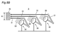
図7Aは、従来の太陽光発電装置の平面図であり、図7Bはその側面図である。図8Aは集光装置3の平面図であり、図8Bはその側面図である。
FIG. 7A is a plan view of a conventional photovoltaic power generation apparatus, and FIG. 7B is a side view thereof. FIG. 8A is a plan view of the
図7A及び図7Bを参照して、従来の太陽光発電装置は、受光装置(レシーバ)350と、複数の反射部材37とを備える。反射部材37は、太陽光S0を受け、全反射して受光装置35に導く。しかしながら、反射部材37は、太陽光S0の幅を小さくできない。従来の太陽光発電装置では、受光装置350は、各反射部材37の出射光S1を受けるため、受光装置350の幅WP及び高さHPを大きくしなければならない。換言すれば、従来の太陽光発電装置はコンパクト化しにくく、集光効率も高くない。
Referring to FIGS. 7A and 7B, the conventional solar power generation device includes a light receiving device (receiver) 350 and a plurality of reflecting
一方、図8A及び図8Bを参照して、集光装置3を太陽光発電に利用する場合、各集束装置30が太陽光S0を集束して光S1を出射する。上述のとおり、光S1の幅は太陽光S0よりも小さい。そのため、同じ太陽光量に対して、集光装置3の受光装置35の幅WI及び高さHIは、従来の太陽光発電装置の受光装置350の幅WP及び高さHPよりも小さくすることができる。したがって、集光装置3は従来よりもコンパクト化が可能であり、集光効率も高くなる。
On the other hand, with reference to FIG. 8A and FIG. 8B, when using the
[第2の実施の形態]
第1の実施の形態では、光学シート311及び315を円形状とし、円環状の線状プリズム314及び318を利用する。しかしながら、線状プリズムは円形状でなくてもよい。
[Second Embodiment]
In the first embodiment, the
第2の実施の形態による集光装置は、集束装置30に代えて、図9に示す集束装置50を備える。集束装置50は、光学部材31に代えて光学部材51を備え、反射部材32及び33に代えて反射部材52を備える。集束装置50のその他の構成は、集束装置30と同じである。
The condensing device according to the second embodiment includes a focusing
光学部材51は、太陽1から受けた平行光S0を屈折して光S1を出射する。反射部材52は、光S1を反射し、受光装置35に導く。
The
図10Aは、光学部材51の平面図である。図10Bは、図10A中の線分B´−B´線での断面図である。図10A及び図10Bを参照して、光学部材51は、光学シート511と、光学シート515とを備える。
FIG. 10A is a plan view of the
光学シート511は、表面512と、構造化面513とを有する。表面512は、平行光源(つまり太陽)と対向する。構造化面513は、表面512と反対側に配置される。
The
構造化面513には、複数の線状プリズム514が配置される。線状プリズム514は、線状プリズム314と異なり、長手方向に伸びる直線状である。図10Aに示すとおり、複数の線状プリズム514は、線状プリズム514の幅方向に配列される。
A plurality of
光学シート515は、構造化面516と表面517とを有する。構造化面516は構造化面513と対向し、表面517は構造化面516と反対側に配置される。構造化面516は複数の線状プリズム518を備える。線状プリズム518は、線状プリズム514の長手方向に伸びる。そして、複数の線状プリズム518は、線状プリズム518の幅方向に配列される。
The
要するに、光学シート511及び515は、光学シート311及び315と比較して、円環状の線状プリズム314及び318に代えて、直線状の線状プリズム514及び518を備える。
In short, the
図11は、図10B中の領域IXの拡大図であり、図12は、図10中の領域Xの拡大図である。図11を参照して、線状プリズム514の横断形状は、線状プリズム314と同様である。線状プリズム514は、主傾斜面514Aと補助傾斜面514Bとを備える。表面512に垂直に入射した平行光S0は、主傾斜面514Aで主として屈折して外部に出射する。補助傾斜面314Bと同様に、補助傾斜面514Bは、光S0を屈折しない方が好ましい。したがって、好ましい補助傾斜面514Bと表面512との角度は90°±5°であり、より好ましくは、90°±2°である。
11 is an enlarged view of region IX in FIG. 10B, and FIG. 12 is an enlarged view of region X in FIG. Referring to FIG. 11, the transverse shape of
図12を参照して、線状プリズム518は、主傾斜面518Aと、補助傾斜面518Bとを備える。線状プリズム518の横断形状は、線状プリズム318と同様である。主傾斜面518Aは、主傾斜面514Aの出射光を受ける。好ましくは、補助傾斜面514Bは、光学シート511の出射光S0と略平行である。具体的には、出射光S0と補助傾斜面514Bとがなす角度は、±5°以内である。この場合、光学シート515の出射光S0の指向性が向上する。さらに好ましくは、主傾斜面518Aは、出射光S0に対して略垂直である。具体的には、主傾斜面318Aと出射光S0とがなす角は、90°±5°であるのが好ましい。
Referring to FIG. 12,
以上のとおり、線状プリズム514及び518が直線状であっても、本発明の効果が奏される。図11及び図12に示すとおり、光学部材51は、光学シート511及び515を利用して、光S0を2段階で屈折して光S1として出射する。このとき、図10Bに示すとおり、光学部材51から出射する光S1の幅W2は、光S0の幅W0よりも小さくなる。要するに、光学部材51も、光学部材31と同様に、光S0を集束した光S1を出射する。そのため、集束装置50も、集束装置30と同様に、集光効率を高め、集光装置をコンパクト化する。
As described above, even if the
[第3の実施の形態]
上述の実施の形態では、集光装置を太陽光発電システムとして利用した。しかしながら、本発明による集光装置は、採光システムにも利用できる。
[Third Embodiment]
In the above-described embodiment, the light collecting device is used as a solar power generation system. However, the light collecting device according to the present invention can also be used in a daylighting system.
図13は、本実施の形態による集光装置7の構成図である。集光装置7は、平行光源である太陽1の光S0を、集束して屋内100に導く。
FIG. 13 is a configuration diagram of the
集光装置7は、光学部材31と、受光装置700とを備える。光学部材31の構成は、第1の実施の形態と同じである(図3〜図6参照)。本実施の形態では、1つの光学部材31が太陽1の移動に伴い角度を変更し(図13中の符号31A、31B、31C)、太陽光S0を常時垂直に受ける。
The condensing
受光装置700は、光学部材31の出射光を受け、屋内100に伝送する。屋内100は、壁面110及び120で囲まれた空間である。受光装置700は、集光部材70と、反射部材71とを備える。集光部材70は、光学部材31の出射光S1を受け、出射光S1を反射部材71に導く。反射部材71は、出射光を全反射して屋内100に伝送する。
The
壁面110には、たとえば拡散レンズ751が配置される。反射部材71は、光S1を拡散レンズ751に導く。拡散レンズ751は、光S1を拡散して屋内100に出射する。
For example, a
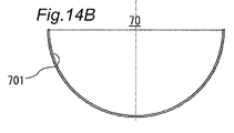
図14Aは、集光部材70の平面図であり、図14Bは正面図である。図14Cは、図14A中の線分C―Cでの断面図である。図13、図14A〜図14Cを参照して、集光部材70は、凹状にくぼんだ反射層701を備える。反射層701は、その表面において光S1を全反射する。図13に示すとおり、光学部材31の出射光S1は、光学部材31の角度に依存することなく集光点80を通過する。具体的には、互いに角度が異なる光学部材31A、31B、31Cからの出射光S1はいずれも、集光点80を通る。
14A is a plan view of the
図14A〜図14Cを参照して、反射層701の表面の曲率は、集光点80との距離が近いほど大きく、集光点80から離れるほど小さい。換言すれば、反射層701の表面の曲率半径は、集光点80との距離が近づくほど、小さくなる。このような構成により、集光部材70は、異なる方向から入射される出射光S1を反射部材71に導くことができる。
Referring to FIGS. 14A to 14C, the curvature of the surface of the
以上の構成を有する集光装置7は、光S0を集束した光S1を出射する。そのため、集光効率が高まり、集光装置7をコンパクト化できる。上述の実施の形態では、光学部材31を利用したが、光学部材31に代えて、光学部材51を利用してもよい。また、受光装置700は、集光部材70を備えなくてもよい。受光装置700は出射光S1を伝送できればよい。また、受光装置700はたとえば、反射部材71に代えて、図15に示すように、内面に反射層を有する伝送ダクトであってもよい。この場合、光S1は、伝送ダクト内を全反射しながら屋内100に導かれる。さらに、受光装置700は、光S1を直接受ける光ファイバ等であってもよい。
The condensing
[第4の実施の形態]
本発明による集光装置は、光センサにも利用できる。図16を参照して、光センサに利用される集光装置8は、図示しない光源と、光学部材31と、受光装置81とを備える。光源はLED等で構成され、平行光を出射する。光学部材31の構成は第1の実施の形態と同じである。受光装置81は、いわゆる受光部であり、出射光を検知し、検知結果を外部に出力する。
[Fourth Embodiment]
The condensing device according to the present invention can also be used for an optical sensor. Referring to FIG. 16, the
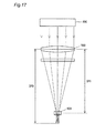
図17は、従来の光学センサの構成図である。従来の光学センサは、光源400と、光学部材であるレンズ500と、受光装置600とを備える。従来の光学センサでは、レンズ500を使用する。そのため、光軸焦点距離DP0近傍に受光装置600を配置する必要がある。したがって、受光装置600とレンズ500との間の距離DP1は、光軸焦点距離DP0に依存し、短くすることができない。そのため、従来の光学センサはコンパクト化しにくい。
FIG. 17 is a configuration diagram of a conventional optical sensor. The conventional optical sensor includes a
一方、図16に示す集光装置8では、光学部材31が光S0を集束して光S1を出射する。光学部材31は光学シート311及び315を含み、光軸焦点距離に依存せず、光S0を集束できる。そのため、光学部材31と受光装置81との間の距離DIは、距離DP1よりも顕著に短くすることができる。その結果、集光装置8は従来の光学センサよりもコンパクト化される。
On the other hand, in the
上述の実施の形態では、集光装置8は光学部材31を利用した。しかしながら、図18に示すとおり、集光装置8は、光学部材31に代えて、光学部材51を利用してもよい。この場合であっても、集光装置8は、従来の光学センサと比較してヒンパクト化できる。
図18の集光装置8は、1つの光学部材51を備える。しかしながら、集光装置8は、複数の光学部材51を備えてもよい。たとえば、図18に示す受光装置81の位置に、2つ目の光学部材51が配置される。このとき、2つ目の光学部材51は、1つ目の光学部材51と異なる方向に光を集光するよう配置する。そして、2つ目の光学部材51の出射光の出射方向に受光装置81が配置される。この場合、集光装置8は、光を2方向(たとえば上下方向及び左右方向)に集光できる。
In the above-described embodiment, the
The
[他の実施の形態]
第1及び第2の実施の形態で利用した光学部材31及び51は、2つの光学シートを利用する。しかしながら、光学部材31及び51は、3以上の光学シートを備えてもよい。たとえば、光学部材51は、図19に示すとおり、光学シート511と、515と、520とを備えてもよい。光学シート520は、表面517と対向する構造化面521と、構造化面521と反対側の表面522とを備える。構造化面521の構成は構造化面518と同じである。具体的には、構造化面521は、主傾斜面521Aと、補助傾斜面521Bとを備える。
[Other embodiments]
The
また、光学部材31は、光学シート311を備え、光学シート315を備えなくてもよい。この場合であっても、光S0をある程度集束した光S1を出射することができる。この場合、光学シート311の下面(構造化面313)上に反射部材319が配置される。同様に、光学部材51は、光学シート511を備え、光学シート515を備えなくてもよい。
The
第1の実施の形態では、好ましくは、補助傾斜面314Bが構造化面313に対して略垂直である。しかしながら、たとえば、補助傾斜面314Bが、第1構造化面313に対して90°よりも小さい角度を有してもよいし、90°よりも大きい角度を有してもよい。
In the first embodiment, preferably, the auxiliary
第1の実施の形態では、光学部材31の背後に反射部材32が設けられ、反射部材32の上部に反射部材33が設けられことにより、反射部材32,33が光S1を受光装置35に伝送する。しかしながら、集束装置30の構成はこれに限定されない。たとえば、反射部材32及び33を備えず、受光装置35は光学部材31の出射光S1を直接受光してもよい。
In the first embodiment, the reflecting
第1の実施の形態における光学部材31を想定してシミュレーションを実施し、光S0と光S1との面積比を求めた。具体的には、図3〜図6に示す光学部材31において、主傾斜面314Aと平面312とがなす角度を37.7°とし、主傾斜面318Aと平面317とがなす角度を38.79°とした。また、補助傾斜面318Bと表面317とがなす角度を51.21°とした。光学シート311及び315の直径はともに220mmとした。反射部材319の円錐の底面の直径を20mmとした。線状プリズム314及び線状プリズム318の屈折率を1.59とした。
Simulation was performed assuming the
シミュレートの結果、光S1の面積は、光S0の面積(つまり、表面312の表面積の1%になった。 As a result of the simulation, the area of the light S1 is 1% of the area of the light S0 (that is, the surface area of the surface 312).
実施例1と異なる形状の光学部材31を想定してシミュレーションを実施した。主傾斜面314Aと表面312とがなす角度を41.8°とし、主傾斜面318Aと表面317とがなす角度を41.48°とした。補助傾斜面318Bと表面317とがなす角度を48.52°とした。反射部材319の円錐の底面の直径を36mmとした。線状プリズム314及び線状プリズム318の屈折率を1.49とした。その他の条件は、実施例1と同じとした。
The simulation was performed assuming an
シミュレートの結果、光S1の面積は、光S0の面積の3.3%になった。 As a result of the simulation, the area of the light S1 is 3.3% of the area of the light S0.
図19に示す光学部材51を想定してシミュレーションを実施し、光S0と光S1との面積比を求めた。具体的には、図19に示す光学部材51(3枚の光学シート511、515及び520において、主傾斜面514Aと表面512とがなす角度を30.3°とし、主傾斜面318Aと表面517とがなす角度を23.04°とした。補助傾斜面518Bと表面517とがなす角度を66.96°とした。主傾斜面521Aと表面522とがなす角度を38.48°とし、補助傾斜面521Bと表面522とがなす角度を51.52°とした。構造化面513、515及び520の各線状プリズムの屈折率を1.59とした。各光学シートの形状は、100mm×100mmの正方形状とした。
A simulation was performed assuming the
シミュレートの結果、光S1の面積は、光S0の面積の14.48%になった。 As a result of the simulation, the area of the light S1 is 14.48% of the area of the light S0.
以上、本発明の実施の形態を説明したが、上述した実施の形態は本発明を実施するための例示に過ぎない。よって、本発明は上述した実施の形態に限定されることなく、その趣旨を逸脱しない範囲内で上述した実施の形態を適宜変形して実施することが可能である。 While the embodiments of the present invention have been described above, the above-described embodiments are merely examples for carrying out the present invention. Therefore, the present invention is not limited to the above-described embodiment, and can be implemented by appropriately modifying the above-described embodiment without departing from the spirit thereof.
1、400 平行光源
3、7、8 集光装置
30、50 集束装置
31、51 光学部材
35、81、350 受光装置
70 集光部材
81 受光装置
311、315、511、515 光学シート
312、317、512 表面
313、316、513、516 構造化面
314、318、514、518 線状プリズム
314A、318A、514A、518A 主傾斜面
314B、318B、514B、518B 補助傾斜面
319 反射部材
DESCRIPTION OF SYMBOLS 1,400 Parallel
Claims (12)
前記集束装置からの出射光を受ける受光装置とを備え、
前記集束装置は、
平行光源と対向する第1表面と、前記第1表面と反対側に配置され前記平行光源からの光を出射する第1構造化面とを有する第1光学シートを備え、
前記第1構造化面は、配列された複数の第1線状プリズムを含む、集光装置。 A focusing device that receives and emits light from a parallel light source;
A light receiving device for receiving light emitted from the focusing device;
The focusing device includes:
A first optical sheet having a first surface facing the parallel light source, and a first structured surface disposed on the opposite side of the first surface and emitting light from the parallel light source;
The first structured surface includes a plurality of arranged first linear prisms.
前記集束装置はさらに、
前記第1構造化面と対向する第2光学シートを備え。
前記第2光学シートは、
前記第1構造化面と対向する第2構造化面と、
前記第2構造化面と反対側の第2表面とを備え、
前記第2構造化面は、前記第1線状プリズムの長手方向に沿って延びる複数の第2線状プリズムを含み、
前記受光装置は、前記第2表面からの前記出射光を受ける、集光装置。 The light collecting device according to claim 1,
The focusing device further includes
A second optical sheet facing the first structured surface;
The second optical sheet is
A second structured surface opposite the first structured surface;
A second surface opposite to the second structured surface;
The second structured surface includes a plurality of second linear prisms extending along a longitudinal direction of the first linear prism;
The light receiving device receives the emitted light from the second surface.
前記複数の第1及び第2線状プリズムは中心軸周りに同心円状に配置され、前記第2表面は前記中心軸に向かって光を出射し、
前記集束装置はさらに、
前記第2プリズムシートの前記第2表面側の前記中心軸上に配置され、前記第2表面から離れるに従って幅が狭くなる反射部材を備える、集光装置。 The light collecting device according to claim 2,
The plurality of first and second linear prisms are arranged concentrically around a central axis, and the second surface emits light toward the central axis,
The focusing device further includes
A light condensing device, comprising: a reflecting member that is disposed on the central axis on the second surface side of the second prism sheet and has a width that decreases as the distance from the second surface increases.
前記第1線状プリズムは、
第1主傾斜面と、前記第1主傾斜面と背向して配置される第1補助傾斜面とを有し、
第2線状プリズムは、
第2補助傾斜面と、
前記第1主傾斜面から出射した光とのなす角度が前記第2補助傾斜面よりも大きい第2主傾斜面とを有し、
前記第1及び第2主傾斜面は前記中心軸と反対側に傾斜する、集光装置。 The light collecting device according to claim 3,
The first linear prism is
A first main inclined surface, and a first auxiliary inclined surface disposed opposite to the first main inclined surface,
The second linear prism is
A second auxiliary inclined surface;
An angle formed by light emitted from the first main inclined surface is larger than the second auxiliary inclined surface;
The first and second main inclined surfaces are inclined to the opposite side of the central axis.
前記複数の第1線状プリズムは中心軸周りに同心円状に配置され、前記第1主傾斜面は前記中心軸と反対側に傾斜し、
前記集束装置はさらに、
前記第1プリズムシートの前記第1構造化面側に前記第1線状プリズムと同軸に配置され、前記第1構造化面から離れるに従って幅が狭くなる円錐状の反射部材を備える、集光装置。 The light collecting device according to claim 1,
The plurality of first linear prisms are arranged concentrically around a central axis, and the first main inclined surface is inclined to the opposite side of the central axis,
The focusing device further includes
A condensing device, comprising: a conical reflecting member disposed coaxially with the first linear prism on the first structured surface side of the first prism sheet and having a width that decreases as the distance from the first structured surface increases. .
第2線状プリズムは、
第2補助傾斜面と、
前記第1主傾斜面から出射した光とのなす角度が、前記第2補助傾斜面よりも大きい第2主傾斜面とを有する、集光装置。 The light collecting device according to claim 2,
The second linear prism is
A second auxiliary inclined surface;
A condensing device having a second main inclined surface having an angle formed with light emitted from the first main inclined surface that is larger than that of the second auxiliary inclined surface.
前記平行光源は太陽であり、
前記受光装置は太陽電池又は太陽発電用レシーバである、集光装置。 It is a condensing device of any one of Claims 1-6,
The parallel light source is the sun;
The light receiving device is a light collecting device, which is a solar cell or a solar power receiver.
前記平行光源は太陽であり、
前記受光装置は受けた出射光を伝送する、集光装置。 It is a condensing device of any one of Claims 1-6,
The parallel light source is the sun;
The light receiving device is a condensing device that transmits received outgoing light.
前記集束装置は、前記平行光源の移動に応じて角度が調整され、前記出射光は、前記角度に依存することなく集光点を通過し、
前記受光装置はさらに、集光部材を備え、
前記集光部材は、前記出射光を受ける凹状の反射層を備え、
前記反射層の表面は、前記集光点からの距離が近いほど大きな曲率を有し、
前記受光装置は、前記集光部材が受けた出射光を伝送する、集光装置。 The light collecting device according to claim 8,
The angle of the focusing device is adjusted according to the movement of the parallel light source, and the emitted light passes through the condensing point without depending on the angle,
The light receiving device further includes a light collecting member,
The condensing member includes a concave reflective layer that receives the emitted light,
The surface of the reflective layer has a larger curvature as the distance from the condensing point is closer,
The light receiving device is a light collecting device that transmits outgoing light received by the light collecting member.
前記受光装置は、前記出射光を検知する、集光装置。 It is a condensing device of any one of Claims 1-6,
The light receiving device is a light collecting device that detects the emitted light.
Priority Applications (1)
| Application Number | Priority Date | Filing Date | Title |
|---|---|---|---|
| JP2011054476A JP2012189280A (en) | 2011-03-11 | 2011-03-11 | Light-condensing device, converging device and lens sheet |
Applications Claiming Priority (1)
| Application Number | Priority Date | Filing Date | Title |
|---|---|---|---|
| JP2011054476A JP2012189280A (en) | 2011-03-11 | 2011-03-11 | Light-condensing device, converging device and lens sheet |
Publications (1)
| Publication Number | Publication Date |
|---|---|
| JP2012189280A true JP2012189280A (en) | 2012-10-04 |
Family
ID=47082656
Family Applications (1)
| Application Number | Title | Priority Date | Filing Date |
|---|---|---|---|
| JP2011054476A Withdrawn JP2012189280A (en) | 2011-03-11 | 2011-03-11 | Light-condensing device, converging device and lens sheet |
Country Status (1)
| Country | Link |
|---|---|
| JP (1) | JP2012189280A (en) |
Cited By (2)
| Publication number | Priority date | Publication date | Assignee | Title |
|---|---|---|---|---|
| WO2013058381A1 (en) * | 2011-10-19 | 2013-04-25 | 株式会社ニコン | Optical condenser device, optical power generation device and photothermal conversion device |
| WO2019181450A1 (en) * | 2018-03-20 | 2019-09-26 | 三菱電機株式会社 | Daylighting member |
-
2011
- 2011-03-11 JP JP2011054476A patent/JP2012189280A/en not_active Withdrawn
Cited By (4)
| Publication number | Priority date | Publication date | Assignee | Title |
|---|---|---|---|---|
| WO2013058381A1 (en) * | 2011-10-19 | 2013-04-25 | 株式会社ニコン | Optical condenser device, optical power generation device and photothermal conversion device |
| US9046279B2 (en) | 2011-10-19 | 2015-06-02 | Nikon Corporation | Light condensing device, photovoltaic power generation device and photo-thermal conversion device |
| TWI574043B (en) * | 2011-10-19 | 2017-03-11 | 尼康股份有限公司 | A light collecting device, a photovoltaic device and a light and heat conversion device |
| WO2019181450A1 (en) * | 2018-03-20 | 2019-09-26 | 三菱電機株式会社 | Daylighting member |
Similar Documents
| Publication | Publication Date | Title |
|---|---|---|
| JP5944398B2 (en) | Turning optics for heat collection and lighting systems | |
| JP5078419B2 (en) | Light emitting module and light receiving module | |
| WO2013147008A1 (en) | Secondary lens, solar cell mounting body, light gathering solar energy unit, light gathering solar energy device, and light gathering solar energy module | |
| KR20100072005A (en) | Compact optics for concentration, aggregation and illumination of light energy | |
| JP2002043629A (en) | Led projector and lens body for use therein | |
| WO2011079856A1 (en) | Photovoltaic concentrator with optical stepped lens and optical stepped lens | |
| US8767302B2 (en) | Laminated optical disk | |
| EP2343578A1 (en) | A fresnel-type lens | |
| JP2012189280A (en) | Light-condensing device, converging device and lens sheet | |
| JP5620212B2 (en) | Concentrator and concentrator | |
| JP2007073774A (en) | Solar battery | |
| KR20110125494A (en) | Sunlight collector | |
| KR101007649B1 (en) | Light guider having multiple channels | |
| JP2008066133A (en) | Light collecting method and board | |
| JP2014010251A (en) | Secondary lens, solar-cell mounting body, condensing type photovoltaic power generation system and condensing type photovoltaic power generation module | |
| US20120170144A1 (en) | Solar concentration device | |
| JPWO2013058381A1 (en) | Condensing device, photovoltaic power generation device, and photothermal conversion device | |
| CN203587825U (en) | Fresnel condenser for concentrating photovoltaic assembly | |
| JP2019185944A (en) | Light condensing unit and sunlight receiving device | |
| JP5296238B2 (en) | Condensing lens module | |
| JP2013083734A (en) | Optical module and optical system | |
| EP4328633A1 (en) | Concentrating lens, photodetector with concentrating lens, concentrating lens unit technical field | |
| CN209842116U (en) | Light-gathering prism | |
| CN102195521A (en) | Pantile condensing apparatus | |
| JP2010014826A (en) | Solar lens |
Legal Events
| Date | Code | Title | Description |
|---|---|---|---|
| A300 | Withdrawal of application because of no request for examination |
Free format text: JAPANESE INTERMEDIATE CODE: A300 Effective date: 20140513 |