WO2013147008A1 - Secondary lens, solar cell mounting body, light gathering solar energy unit, light gathering solar energy device, and light gathering solar energy module - Google Patents
Secondary lens, solar cell mounting body, light gathering solar energy unit, light gathering solar energy device, and light gathering solar energy module Download PDFInfo
- Publication number
- WO2013147008A1 WO2013147008A1 PCT/JP2013/059224 JP2013059224W WO2013147008A1 WO 2013147008 A1 WO2013147008 A1 WO 2013147008A1 JP 2013059224 W JP2013059224 W JP 2013059224W WO 2013147008 A1 WO2013147008 A1 WO 2013147008A1
- Authority
- WO
- WIPO (PCT)
- Prior art keywords
- secondary lens
- light
- lens
- power generation
- solar
- Prior art date
Links
- 230000003287 optical effect Effects 0.000 claims abstract description 202
- 238000010248 power generation Methods 0.000 claims description 185
- 230000002093 peripheral effect Effects 0.000 claims description 91
- 239000000463 material Substances 0.000 claims description 77
- 239000000758 substrate Substances 0.000 claims description 37
- 230000007423 decrease Effects 0.000 claims description 24
- 238000005520 cutting process Methods 0.000 claims description 13
- 230000035945 sensitivity Effects 0.000 claims description 11
- 239000011347 resin Substances 0.000 claims description 10
- 229920005989 resin Polymers 0.000 claims description 10
- 238000013459 approach Methods 0.000 claims description 6
- 230000004907 flux Effects 0.000 claims 1
- 210000004027 cell Anatomy 0.000 description 451
- 238000004519 manufacturing process Methods 0.000 description 32
- 238000009826 distribution Methods 0.000 description 26
- 238000006243 chemical reaction Methods 0.000 description 24
- 230000000694 effects Effects 0.000 description 22
- 238000010586 diagram Methods 0.000 description 21
- 239000011521 glass Substances 0.000 description 21
- 239000010410 layer Substances 0.000 description 13
- 230000009471 action Effects 0.000 description 12
- 229920002050 silicone resin Polymers 0.000 description 8
- 239000012141 concentrate Substances 0.000 description 7
- 239000000945 filler Substances 0.000 description 7
- 229920003229 poly(methyl methacrylate) Polymers 0.000 description 7
- 239000004926 polymethyl methacrylate Substances 0.000 description 7
- 230000009467 reduction Effects 0.000 description 6
- 230000008859 change Effects 0.000 description 5
- 230000000052 comparative effect Effects 0.000 description 5
- 239000006185 dispersion Substances 0.000 description 5
- 230000006872 improvement Effects 0.000 description 5
- 238000000465 moulding Methods 0.000 description 5
- 238000000149 argon plasma sintering Methods 0.000 description 4
- 238000005452 bending Methods 0.000 description 4
- 230000001678 irradiating effect Effects 0.000 description 4
- 239000004417 polycarbonate Substances 0.000 description 4
- 229920000515 polycarbonate Polymers 0.000 description 4
- 238000004088 simulation Methods 0.000 description 4
- 229910001218 Gallium arsenide Inorganic materials 0.000 description 3
- 230000004075 alteration Effects 0.000 description 3
- 238000003384 imaging method Methods 0.000 description 3
- 239000011241 protective layer Substances 0.000 description 3
- 239000004925 Acrylic resin Substances 0.000 description 2
- 229920000178 Acrylic resin Polymers 0.000 description 2
- -1 CuInGaSe Inorganic materials 0.000 description 2
- 239000005388 borosilicate glass Substances 0.000 description 2
- 230000015556 catabolic process Effects 0.000 description 2
- 150000001875 compounds Chemical class 0.000 description 2
- 238000005336 cracking Methods 0.000 description 2
- 230000007547 defect Effects 0.000 description 2
- 238000006731 degradation reaction Methods 0.000 description 2
- 238000000034 method Methods 0.000 description 2
- 230000008569 process Effects 0.000 description 2
- 238000002834 transmittance Methods 0.000 description 2
- 239000013585 weight reducing agent Substances 0.000 description 2
- 229910004613 CdTe Inorganic materials 0.000 description 1
- 101100208473 Neurospora crassa (strain ATCC 24698 / 74-OR23-1A / CBS 708.71 / DSM 1257 / FGSC 987) lcm-2 gene Proteins 0.000 description 1
- VYPSYNLAJGMNEJ-UHFFFAOYSA-N Silicium dioxide Chemical compound O=[Si]=O VYPSYNLAJGMNEJ-UHFFFAOYSA-N 0.000 description 1
- 238000010521 absorption reaction Methods 0.000 description 1
- 230000015572 biosynthetic process Effects 0.000 description 1
- 230000003247 decreasing effect Effects 0.000 description 1
- 238000006073 displacement reaction Methods 0.000 description 1
- 230000012447 hatching Effects 0.000 description 1
- 229910010272 inorganic material Inorganic materials 0.000 description 1
- 239000011147 inorganic material Substances 0.000 description 1
- 230000007774 longterm Effects 0.000 description 1
- 230000000116 mitigating effect Effects 0.000 description 1
- 229910021421 monocrystalline silicon Inorganic materials 0.000 description 1
- 239000005304 optical glass Substances 0.000 description 1
- 238000013041 optical simulation Methods 0.000 description 1
- 230000035699 permeability Effects 0.000 description 1
- 229910021420 polycrystalline silicon Inorganic materials 0.000 description 1
- 239000007787 solid Substances 0.000 description 1
- 239000006097 ultraviolet radiation absorber Substances 0.000 description 1
Images


Classifications
-
- H—ELECTRICITY
- H01—ELECTRIC ELEMENTS
- H01L—SEMICONDUCTOR DEVICES NOT COVERED BY CLASS H10
- H01L31/00—Semiconductor devices sensitive to infrared radiation, light, electromagnetic radiation of shorter wavelength or corpuscular radiation and specially adapted either for the conversion of the energy of such radiation into electrical energy or for the control of electrical energy by such radiation; Processes or apparatus specially adapted for the manufacture or treatment thereof or of parts thereof; Details thereof
- H01L31/02—Details
- H01L31/0232—Optical elements or arrangements associated with the device
- H01L31/02325—Optical elements or arrangements associated with the device the optical elements not being integrated nor being directly associated with the device
-
- H—ELECTRICITY
- H01—ELECTRIC ELEMENTS
- H01L—SEMICONDUCTOR DEVICES NOT COVERED BY CLASS H10
- H01L31/00—Semiconductor devices sensitive to infrared radiation, light, electromagnetic radiation of shorter wavelength or corpuscular radiation and specially adapted either for the conversion of the energy of such radiation into electrical energy or for the control of electrical energy by such radiation; Processes or apparatus specially adapted for the manufacture or treatment thereof or of parts thereof; Details thereof
- H01L31/04—Semiconductor devices sensitive to infrared radiation, light, electromagnetic radiation of shorter wavelength or corpuscular radiation and specially adapted either for the conversion of the energy of such radiation into electrical energy or for the control of electrical energy by such radiation; Processes or apparatus specially adapted for the manufacture or treatment thereof or of parts thereof; Details thereof adapted as photovoltaic [PV] conversion devices
- H01L31/054—Optical elements directly associated or integrated with the PV cell, e.g. light-reflecting means or light-concentrating means
- H01L31/0543—Optical elements directly associated or integrated with the PV cell, e.g. light-reflecting means or light-concentrating means comprising light concentrating means of the refractive type, e.g. lenses
-
- H—ELECTRICITY
- H01—ELECTRIC ELEMENTS
- H01L—SEMICONDUCTOR DEVICES NOT COVERED BY CLASS H10
- H01L31/00—Semiconductor devices sensitive to infrared radiation, light, electromagnetic radiation of shorter wavelength or corpuscular radiation and specially adapted either for the conversion of the energy of such radiation into electrical energy or for the control of electrical energy by such radiation; Processes or apparatus specially adapted for the manufacture or treatment thereof or of parts thereof; Details thereof
- H01L31/02—Details
- H01L31/0216—Coatings
- H01L31/02161—Coatings for devices characterised by at least one potential jump barrier or surface barrier
- H01L31/02167—Coatings for devices characterised by at least one potential jump barrier or surface barrier for solar cells
- H01L31/02168—Coatings for devices characterised by at least one potential jump barrier or surface barrier for solar cells the coatings being antireflective or having enhancing optical properties for the solar cells
-
- H—ELECTRICITY
- H01—ELECTRIC ELEMENTS
- H01L—SEMICONDUCTOR DEVICES NOT COVERED BY CLASS H10
- H01L31/00—Semiconductor devices sensitive to infrared radiation, light, electromagnetic radiation of shorter wavelength or corpuscular radiation and specially adapted either for the conversion of the energy of such radiation into electrical energy or for the control of electrical energy by such radiation; Processes or apparatus specially adapted for the manufacture or treatment thereof or of parts thereof; Details thereof
- H01L31/04—Semiconductor devices sensitive to infrared radiation, light, electromagnetic radiation of shorter wavelength or corpuscular radiation and specially adapted either for the conversion of the energy of such radiation into electrical energy or for the control of electrical energy by such radiation; Processes or apparatus specially adapted for the manufacture or treatment thereof or of parts thereof; Details thereof adapted as photovoltaic [PV] conversion devices
- H01L31/042—PV modules or arrays of single PV cells
- H01L31/048—Encapsulation of modules
-
- Y—GENERAL TAGGING OF NEW TECHNOLOGICAL DEVELOPMENTS; GENERAL TAGGING OF CROSS-SECTIONAL TECHNOLOGIES SPANNING OVER SEVERAL SECTIONS OF THE IPC; TECHNICAL SUBJECTS COVERED BY FORMER USPC CROSS-REFERENCE ART COLLECTIONS [XRACs] AND DIGESTS
- Y02—TECHNOLOGIES OR APPLICATIONS FOR MITIGATION OR ADAPTATION AGAINST CLIMATE CHANGE
- Y02E—REDUCTION OF GREENHOUSE GAS [GHG] EMISSIONS, RELATED TO ENERGY GENERATION, TRANSMISSION OR DISTRIBUTION
- Y02E10/00—Energy generation through renewable energy sources
- Y02E10/50—Photovoltaic [PV] energy
- Y02E10/52—PV systems with concentrators
Definitions
- the present invention relates to a secondary lens used in a concentrating solar power generation module that irradiates solar cells with light condensed by a condensing lens, a solar cell mounting body on which the secondary lens is mounted, and a solar cell mounting body.
- the present invention relates to a concentrating solar power generation unit, a concentrating solar power generation device, and a concentrating solar power generation module to which the concentrating solar power generation device is applied.
- a solar power generation device that converts solar energy into electric power has been put into practical use.
- the solar cells smaller than the condensing lens are irradiated with sunlight condensed by the condensing lens.
- a concentrating solar power generation device to be taken out has been proposed.
- the solar battery cell Since the concentrating solar power generation device condenses sunlight with a condensing lens, the solar battery cell only needs to have a small light receiving area capable of receiving sunlight condensed by the optical system. In other words, since the solar cells having a size smaller than the light receiving area of the condensing lens may be used, the size of the solar cells can be reduced, and the occupied amount of the solar cells which are the most expensive components in the photovoltaic power generation apparatus The cost can be reduced by reducing the (use amount). Due to such advantages, the concentrating solar power generation apparatus is being used for power supply in an area where power can be generated using a large area.
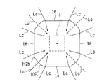
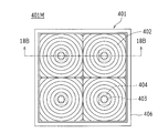
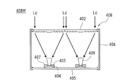
- FIG. 18A is a plan view showing the concentrating solar power generation device 401 and the concentrating solar power generation module 401M as Conventional Example 1 as viewed from the condensing lens 402 side.
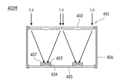
- 18B is a cross-sectional view showing the concentrating solar power generation device 401 and the concentrating solar power generation module 401M shown in FIG. 18A in a cross-sectional state taken along arrows 18B-18B in FIG. 18A.
- a Fresnel condensing lens 402 as a primary condensing optical system is used.
- Sunlight (light Lc) is refracted and collected, and the collected light Lc is irradiated to the solar battery cell 403 for photoelectric conversion (photoelectric generation).
- the receiver substrate 404 on which the solar battery cell 403 is mounted, the holding plate 405 on which the receiver substrate 404 is placed, and the holding plate 405 and the condenser lens 402 are arranged, and the holding plate 405 and the condenser lens 402 are positioned.
- the module frame 406 and the solar battery cell 403 are provided with a translucent surface protective layer 407 that protects the environment such as humidity.
- the light Lc condensed by the condensing lens 402 is directly irradiated to the solar battery cell 403 through the translucent surface protective layer 407.
- the light Lc refracted by the condenser lens 402 is refracted at different angles depending on the wavelength component. Therefore, it is difficult to collect light accurately and efficiently, and when the condensing lens 402 is a single focus type in order to increase the light collection efficiency, the light Lc is excessively concentrated near the center of the solar battery cell 403.
- the condensing lens 402 is often formed of a translucent resin material such as PMMA (polymethyl methacrylate), silicone resin, or polycarbonate in consideration of processability. Since the refractive index of the translucent resin material changes depending on the temperature, there is a problem that the amount of the light Lc reaching the solar battery cell 403 is changed due to the change of the ambient environment temperature, and the output is easily lowered.
- a translucent resin material such as PMMA (polymethyl methacrylate), silicone resin, or polycarbonate
- Patent Document 2 Conventional example 2 (for example, see Patent Document 2) is known as a solution to such a problem.
- FIG. 19A is a plan view showing the concentrating solar power generation device 408 and the concentrating solar power generation module 408M as Conventional Example 2 as viewed from the condensing lens 402 side.
- FIG. 19B is a schematic diagram schematically illustrating a light condensing state of the light Lc by enlarging the secondary glass 409 applied to the concentrating solar power generation device 401 and the concentrating solar power generation module 401M illustrated in FIG. 19A.
- FIG. 19B is a schematic diagram schematically illustrating a light condensing state of the light Lc by enlarging the secondary glass 409 applied to the concentrating solar power generation device 401 and the concentrating solar power generation module 401M illustrated in FIG. 19A.
- a rod-type secondary glass 409 is added to the concentrating solar power generation device 401 shown in FIG. 18A. Therefore, the concentrating solar power generation device 408 receives the light collected by the condensing lens 402 on the upper surface of the secondary glass 409, and then guides the light by total reflection on the side surface of the secondary glass 409. The solar battery cell 403 is irradiated through the lower surface of the glass 409.
- the concentrating solar power generation device 408 As the incident light Lc passes through the inner side of the secondary glass 409, a light mixing effect is obtained, so that light with little chromatic aberration and intensity unevenness is emitted from the secondary glass 409. As a result, improvement of FF can be expected.
- the incident surface of the secondary glass 409 is formed wider than the exit surface, the tolerance for the deviation of the incident angle of the light Lc and the positional deviation between the condenser lens 402 and the secondary glass 409 is improved. Can also be obtained.
- the secondary glass 409 requires a corresponding optical path, that is, a height.
- Patent Document 2 illustrates a secondary glass 409 having a height of 40 mm. Therefore, in the concentrating solar power generation device 408, there is a problem that the member cost associated with the adoption of the secondary glass 409 increases.
- the secondary glass 409 must be erected on the solar battery cell 403 after the center of the secondary glass 409 and the center of the solar battery cell 403 are accurately aligned. Therefore, a holding member for holding the secondary glass 409 is required, and there are a plurality of problems in terms of cost, such as an excessive number of man-hours required for manufacturing.
- the present invention efficiently concentrates sunlight (light) on the light receiving surface of the solar battery cell, suppresses excessive concentration of light, and suppresses a decrease in electrical characteristics (FF) of the solar battery cell, It aims at providing the secondary lens which can improve the power generation efficiency of a photovoltaic cell.
- the present invention applies a secondary lens according to the present invention, thereby improving the electrical characteristics of the solar battery cell or improving the productivity of the solar battery package, the concentrating solar power generation unit, Another object is to provide a concentrating solar power generation device or a concentrating solar power generation module.
- the secondary lens according to the present invention is used in a concentrating solar power generation module that irradiates solar cells with light condensed by a condensing lens.
- the secondary lens opposes the condensing lens and collects light from the condensing lens.
- the cross-sectional area of the first surface in the direction perpendicular to the optical axis is monotonously increased from the condenser lens side toward the solar cell side, and It is characterized by having at least one inflection point that the inclination angle of the first surface with respect to the surface perpendicular to the optical axis decreases as it approaches the solar cell side from the condenser lens side.
- the concentration of light collected on the surface of the solar battery cell can be alleviated by providing a step with a gentle inclination in the middle of the dome-shaped secondary lens. That is, the power generation efficiency (conversion efficiency) of the solar battery cell can be improved by irradiating the solar battery surface with light uniformly.
- the secondary lens of the present invention may be characterized in that a line passing through the inflection point is located outside the solar battery cell in a plan view viewed from the optical axis direction.
- the concentration of light collected on the surface of the solar battery cell can be reduced. That is, the power generation efficiency (conversion efficiency) of the solar battery cell can be improved by irradiating the solar battery surface with light uniformly.
- the secondary lens of the present invention is a cross section in a direction perpendicular to the optical axis of the optical refracting surface in a region from a top portion of the first surface facing the condenser lens to a line passing through the inflection point.
- the shape may be similar to a cross-sectional shape in a direction perpendicular to the optical axis of the optical refractive surface of the condenser lens.
- the cross-sectional shape in the direction perpendicular to the optical axis of the optical refracting surface in the region from the top facing the condensing lens to the line passing through the inflection point in the first surface is the same as the optical refracting surface of the condensing lens.
- the secondary lens of the present invention is a cross-sectional shape in a direction perpendicular to the optical axis of the optical refracting surface in a partial region from a line passing through the inflection point to the second surface in the first surface.
- it may be characterized by being dissimilar to the cross-sectional shape of the optical refractive surface of the condenser lens in the direction perpendicular to the optical axis.
- the cross-sectional shape in the direction perpendicular to the optical axis of the optical refracting surface of a part of the first surface from the line passing through the inflection point to the second surface is changed to the light of the optical refracting surface of the condenser lens.
- the solar battery cell is a multi-junction solar battery cell, and a region from the line passing through the inflection point to the second surface of the first surface has a short wavelength. It is good also as a structure which the light of the wavelength range corresponding to the photovoltaic cell which has a sensitivity area
- the “configuration where no light is incident” means that the configuration is such a design, and depending on the actual usage environment, it may be incident slightly due to changes in ambient temperature, manufacturing errors, etc. However, it can be said that such incidence is within an allowable range. That is, by design, the inflection point is formed at a position outside the range in which light in the short wavelength region is incident.
- the light in the wavelength region corresponding to the solar cell having the sensitivity region on the short wavelength side is incident on the first optical refracting surface H2a and is not incident on the second optical refracting surface H2b (strictly speaking, almost no Not incident). Therefore, the light in the wavelength region incident on the surface of the solar cell having the sensitivity region on the short wavelength side can be efficiently condensed and irradiated to the solar cell.
- the secondary lens of the present invention is a multi-junction solar cell, and light of a specific wavelength that is emitted from an end of the condensing lens and is incident near the upper portion of the inflection point is the optical axis. After reaching the solar cell after crossing, and before the light of a specific wavelength that has exited from the end of the condenser lens and entered near the lower part of the inflection point intersects the optical axis, the solar cell The height position of the inflection point may be set so as to reach.
- the solar cell surface is obtained by dispersing the traveling direction of the light after incidence before and after the height direction of the inflection point in a direction that crosses the optical axis and a direction that does not cross the optical axis. Since the concentration of light on the center of the solar cell can be alleviated and the surface of the solar cell can be irradiated with light uniformly, the power generation efficiency (conversion efficiency) can be improved.
- the secondary lens of the present invention may be characterized in that the specific wavelength is 650 to 900 nm. According to this configuration, the light of the middle wavelength region, the solar cell surface having the sensitivity region in the middle wavelength region, the concentration of the light to the central portion on the surface of the solar cell having the sensitivity region in the middle wavelength region is alleviated Since light can be irradiated uniformly, power generation efficiency (conversion efficiency) can be improved.
- the secondary lens of the present invention may be characterized in that the distance from the inflection point to the solar battery cell is not less than half of the distance from the vertex of the first surface to the solar battery cell.
- the distance from the inflection point to the solar battery cell is set to be more than half of the distance from the vertex of the first surface to the solar battery cell, so that it is changed to the near side (vertex side) where the light collection efficiency is reduced.
- Inflection points can be provided.
- the concentration of light incident on the region from the inflection point to the second surface can be relaxed, and light can be irradiated uniformly on the surface of the solar battery cell. Can be improved.
- the secondary lens of the present invention may have a configuration in which an intermediate region portion that does not optically contribute to guiding the incident light to the solar battery cell is provided between the first surface and the second surface. .
- the solar cell and the receiver substrate and the secondary lens Even when the translucent filler adheres to the side surface of the secondary lens, that is, the intermediate region when the lens is bonded and fixed, the output characteristics of the solar battery cell are not affected.
- the secondary lens of the present invention may have a configuration in which an antireflection film for suppressing surface reflection is provided on the surface of the first surface.
- This configuration can reduce the loss due to surface reflection when entering the secondary lens, so that the output of the solar cell can be improved.
- the solar cell mounting body of the present invention includes a secondary lens into which the light condensed by the condensing lens is incident, and photoelectrically converts the light emitted from the secondary lens that is disposed facing the secondary lens.
- a solar cell mounting body including a solar cell to be converted and a receiver substrate on which the solar cell is mounted, wherein the secondary lens is a secondary lens having the above-described configuration, and the secondary lens and the sun A filling portion filled with a translucent resin material is provided between the battery cells.
- a translucent resin material is filled between the secondary lens and the solar battery cell to form a filling portion, and an air layer between the secondary lens and the solar battery cell is formed.
- the concentrating solar power generation unit of the present invention includes a condensing lens that condenses light, a secondary lens that emits light incident from the condensing lens, and light emitted from the secondary lens. And a solar cell that photoelectrically converts the secondary lens, wherein the secondary lens is a secondary lens having the above-described configuration.
- the concentrating solar power generation unit According to the concentrating solar power generation unit according to the present invention, light incident on the secondary lens near the optical axis can be efficiently collected and excessive concentration of light can be reduced.
- the light collection efficiency (conversion efficiency) of the cell can be improved.
- the concentrating solar power generation module of the present invention is a concentrating solar power generation module formed by combining a plurality of concentrating solar power generation units having the above-described configuration, and the concentrating solar power generation unit Is a concentrating solar power generation unit configured as described above.
- the power generation efficiency (conversion efficiency) of solar cells can be improved.
- the secondary lens according to the present invention is a secondary lens used in a concentrating solar power generation device including a solar cell and a condensing lens that collects light and irradiates the solar cell.
- An incident portion where the light is incident, and an emission portion that emits the light incident on the incident portion to the solar cell, the incident portion being a top portion facing the condenser lens;
- An intermediate portion positioned between the top portion and the emission portion, the intermediate portion being in a direction perpendicular to a vertical axis defined by a straight line passing through the center of the condenser lens and the center of the solar battery cell.
- the cross-sectional area of the condensing lens increases as it approaches the emitting portion from the top, and at least a part of the outer peripheral shape of the cross-section cuts the optical refractive surface of the condenser lens along a plane perpendicular to the vertical axis. Similar shape to the edge shape of the cross section And characterized in that.
- the area of the cross section of the intermediate part in the direction perpendicular to the vertical axis defined by the straight line passing through the center of the condensing lens and the center of the solar battery cell extends from the top to the emission part.
- the outer peripheral shape of at least a part of the cross section is a shape different from the similar shape of the edge shape of the cross section obtained by cutting the optical refractive surface of the condensing lens along a plane perpendicular to the vertical axis.
- the outer peripheral shape may be a polygon.
- the outer peripheral shape of the secondary lens according to the present invention is a polygon, most of the collected light can be refracted at each side of the polygon, so that the condensing is surely reduced. This further suppresses the decrease in FF.
- the outer peripheral shape may include a straight portion and a curved portion, and more than half of the outer peripheral length of the outer peripheral shape may be the straight portion.
- the secondary lens according to the present invention can refract the light collected by the condenser lens toward the secondary lens at the linear portion of the outer peripheral shape, even when the outer peripheral shape is not a polygon. Since light is refracted in a straight line portion that occupies half or more of the outer peripheral length, it is possible to reliably prevent the concentrated light from being excessively concentrated in the vicinity of the center of the solar battery cell and to reduce the light collection.
- At least a part of the surface of the intermediate portion may be a flat surface.
- the outer peripheral shape in the cross section of the intermediate portion is similar to the edge shape of the cross section of the condensing lens cut by a plane perpendicular to the vertical axis.
- the shape can be different from the shape.
- At least a part of the surface of the intermediate portion may be a curved surface.
- the secondary lens according to the present invention has a curved surface at the intermediate portion, a portion of the light condensed toward the solar cell can be efficiently guided to the solar cell. A reduction in output current due to a light angle shift, a solar cell assembly error, or the like is suppressed, and the power generation amount of the solar cell is improved.
- the curved surface may be characterized in that the outer peripheral shape on the side close to the top is a circle centered on the vertical axis.
- the outer peripheral shape of the cross section on the side closer to the top is a circle centering on the vertical axis, the central region of the secondary lens where light is most concentrated is more concentrated. Since it can be in a highly efficient state, the accuracy of condensing is improved to prevent a decrease in output current, and the power generation amount of the solar battery cell is improved.
- At least a part of the outer peripheral shape may be an arc constituting a part of a circle centered on the vertical axis.
- the secondary lens according to the present invention is a solar cell that efficiently collects the light collected by the condenser lens because a part of the outer peripheral shape is an arc that forms a part of a circle centered on the vertical axis. Since the light can be guided to the cell, the output current is prevented from decreasing due to the angle deviation of the incident light, assembly error, etc. The power generation efficiency of the battery cell is further improved.
- the surface of the intermediate portion may have a ridge line portion, and the ridge line portion may be chamfered.
- the secondary lens according to the present invention is chamfered with respect to the ridgeline of the intermediate portion, optical loss due to light scattering at the ridgeline portion can be avoided, and in the production process The occurrence of damage during handling can be prevented.
- the outer peripheral shape of the cross section near the top and the outer peripheral shape of the cross section near the emitting portion may be different from the similar shape. Good.
- the secondary lens according to the present invention uses the characteristic that the incident position of the incident light refracted by the condenser lens is different depending on the wavelength because the optical characteristic is different between the top part side and the emission part side of the intermediate part. Therefore, the relaxation of the light concentration and the improvement of the light collection efficiency can be balanced.
- the inclination of the surface of the intermediate portion may be larger on the side closer to the emission portion than on the side closer to the top portion.
- the secondary lens according to the present invention has a larger inclination of the intermediate portion on the light emitting portion side than the inclination of the intermediate portion on the top portion side. Therefore, when the secondary lens is not applied, the solar cell (light receiving surface) Light that reaches a position far from the center is refracted at a steeper angle toward the solar battery cell in the direction along the vertical axis, thereby improving the light collection efficiency. Further, since light is refracted on both the top side and the emission side having different inclinations on the surface of the intermediate part, the focal position is changed in the vertical axis direction, and the light in the vertical axis direction (vertical direction) is changed. Concentration can be eased.
- a first inclination angle that is a surface inclination angle closer to the emitting portion is larger than a second inclination angle that is a surface inclination angle closer to the top portion. Also good.
- the secondary lens according to the present invention has no secondary lens because the first inclination angle of the surface on the emission part side in the intermediate part is larger than the second inclination angle of the surface on the top side in the intermediate part. In this case, light reaching a position far from the solar battery cell is refracted at a steeper angle, so that the light collection efficiency can be improved.
- the top may be a flat surface.
- the secondary lens according to the present invention has a flat top portion, the light collected toward the solar cell is reliably guided to the solar cell without excessively refracting the light.
- the concentration of light due to the lens effect as a secondary lens can be suppressed, the decrease in FF is further suppressed.
- the top portion may be a convex curved surface.
- the secondary lens according to the present invention has a curved top part, and thus efficiently concentrates the light collected on the top part by the condenser lens to the solar cell in a state where the concentration of light as a whole is relaxed. Since it emits light, it is possible to increase the power generation amount of the solar cell by suppressing the decrease of the FF and suppressing the decrease of the output current due to the angular deviation of the incident light, the positional deviation of the solar cell, and the like.
- the secondary lens according to the present invention may include a base portion that is disposed between the emitting portion and the intermediate portion and integrated with the intermediate portion.
- the secondary lens according to the present invention includes a base portion that is disposed between the emitting portion and the intermediate portion and integrated with the intermediate portion, the secondary lens is handled using the base portion. Therefore, without damaging the optical characteristics of the secondary lens, the handling and molding in the manufacturing process can be facilitated, the manufacturing process can be streamlined, the production efficiency can be improved, and the member cost can be reduced. .
- an outer periphery of the emitting part and the base part may be a quadrangle.
- the secondary lens according to the present invention has a rectangular outer periphery of the emission part and the base part, and thus can be manufactured by efficiently arranging a large number in the manufacturing process, and the production efficiency can be improved. It can improve and can reduce member cost.
- the height of the base portion may be 0.5 mm or more.
- the height of the base part (the length between the base part side of the intermediate part and the emission part (the thickness of the base part)) is 0.5 mm or more. For this reason, since a certain thickness is ensured, defects such as chipping (chips) are hardly caused by handling with a jig.
- the secondary lens according to the present invention is opposed to the solar battery cell through the translucent material (translucent material filling portion), the translucent material adheres to the side surface (base portion). However, no optical loss occurs.
- the incident portion may include an antireflection film on a surface.
- the secondary lens according to the present invention includes the antireflection film on the surface of the incident portion, it is possible to suppress the reflected light from being reflected on the surface and to reduce the loss due to the surface reflection. , Improve the output of solar cells.
- the secondary lens according to the present invention is formed of a light-transmitting optical material, and the light-transmitting optical material has a refractive index with respect to D-line of greater than 1.35 and less than 1.80, and the refractive index.
- the absolute value of the temperature dependence may be smaller than 1 ⁇ 10 ⁇ 4 .
- the secondary lens according to the present invention has a refractive index in the range of 1.35 to 1.80, the effect of the secondary lens as a refractive element is ensured, and the reflectance of the surface is suppressed to collect the secondary lens. Light efficiency can be maintained high, and even when refractive index fluctuations occur due to temperature rise due to light collection, fluctuations in light collection characteristics can be suppressed, ensuring stable optical characteristics and maintaining high efficiency. can do.
- the solar cell mounting body includes a secondary lens into which the light condensed by the condenser lens is incident, and the light emitted from the secondary lens disposed opposite to the secondary lens.
- a solar cell mounting body comprising a photovoltaic cell for photoelectric conversion and a receiver substrate on which the solar cell is mounted, wherein the secondary lens is a secondary lens according to the present invention, and the secondary lens
- a translucent material filling portion filled with a translucent material is provided between the solar battery cells.
- the solar battery mounting body includes a translucent material filling portion filled with a translucent material between the secondary lens and the solar battery cell, and between the secondary lens and the solar battery cell.
- the thickness of the light transmissive material filling portion may be 0.3 mm or more and 2 mm or less.
- the thickness of the translucent material filling portion formed between the secondary lens and the solar cell is from 0.3 mm to 2 mm.
- the concentrating solar power generation device is a condensing lens that condenses light, a secondary lens that emits light incident from the condensing lens, and the secondary lens that is emitted from the secondary lens.
- a concentrating solar power generation device including a photovoltaic cell for photoelectrically converting light, wherein the secondary lens is a secondary lens according to the present invention.
- the concentrating solar power generation device efficiently collects the light incident on the secondary lens even when the incident light has an angular deviation, a solar cell placement error, and the like. Since excessive concentration of light can be avoided, the power generation efficiency of the solar cell (solar cell) can be improved and the electrical characteristics can be improved.
- the side dimension of the condensing lens in a direction perpendicular to the vertical axis is L1
- the solar cell has a cell perpendicular to the vertical axis.
- the dimension (side dimension of the cell) is L2
- the working distance between the condenser lens and the solar battery cell is Wd
- the top of the secondary lens and the vertical axis intersect from the point Dd may be 1.2 to 1.8 times Wd ⁇ L2 / L1, where Dd is the secondary condensing distance from the light receiving surface of the solar battery cell.
- the concentrating solar power generation device efficiently collects light incident on the secondary lens with high accuracy, and can avoid excessive concentration of light with high accuracy.
- the power generation efficiency of the solar battery (solar battery cell) can be improved and the electrical characteristics can be improved.
- the concentrating solar power generation module according to the present invention is a concentrating solar power generation module formed by combining a plurality of concentrating solar power generation devices, and the concentrating solar power generation device is
- a plurality of the condensing lenses are arranged on a single translucent substrate, and a plurality of the solar cells are arranged on a single holding plate. It is characterized by.
- the concentrating solar power generation module according to the present invention performs the alignment by positioning the condensing lens on a single translucent substrate and positioning the solar cells on a single holding plate. Therefore, it is possible to easily manufacture a concentrating solar power generation module that has been applied and positioned with high accuracy, so that productivity can be improved, manufacturing cost can be reduced, and electrical characteristics can be improved.
- each of the plurality of solar cells is individually mounted on a receiver substrate, and the plurality of receiver substrates are mounted on the holding plate. It is good.
- the concentrating solar power generation module according to the present invention is produced by mounting individual solar cells on individual receiver substrates, the solar cells are easy to handle and workability is improved. , Productivity can be further improved.
- the concentration of light collected on the surface of the solar battery cell can be alleviated by providing a step with a gentle inclination in the middle of the secondary lens. That is, the power generation efficiency (conversion efficiency) of the solar battery cell can be improved by irradiating the solar battery surface with light uniformly.
- the translucent resin material is filled between the secondary lens and the solar cell to form a filling portion, and the air layer between the secondary lens and the solar cell is formed.
- the concentrating solar power generation unit of the present invention it is possible to efficiently collect light incident on the secondary lens near the optical axis, and to reduce excessive concentration of light.
- the power generation efficiency (conversion efficiency) can be improved.
- the power generation efficiency (conversion efficiency) of solar cells can be improved.
- the area of the cross section of the intermediate part increases from the top part to the output part, and at least a part of the outer peripheral shape of the cross section has the optical refractive surface of the condenser lens as the vertical axis. It is a shape different from the similar shape of the edge shape of a cross section cut by a vertical plane.
- the light collected by the condenser lens toward the secondary lens is refracted by the outer peripheral shape of the intermediate portion, so that the collected light is near the center of the solar battery cell. It is possible to prevent excessive concentration, suppress a decrease in FF (curve factor) indicating good electrical characteristics of the solar battery cell, and improve the power generation efficiency of the solar battery cell.
- FF curve factor
- the solar cell mounting body according to the present invention includes a translucent material filling portion in which a translucent material is filled between the secondary lens according to the present invention and the solar battery cell.
- the solar cell mounting body according to the present invention eliminates the air layer between the secondary lens according to the present invention and the solar cell, and thus reflects light at the interface between the secondary lens and the air layer. Since it can suppress, the light emitted from a secondary lens can be efficiently guide
- the concentrating solar power generation device includes the secondary lens according to the present invention.
- the concentrating solar power generation device efficiently collects the light incident on the secondary lens even when the incident light has an angular deviation, a solar cell placement error, and the like. Since excessive concentration of light can be avoided, the power generation efficiency of the solar cell (solar cell) can be improved and the electrical characteristics can be improved.
- the concentrating solar power generation module according to the present invention is a combination of a plurality of concentrating solar power generation apparatuses according to the present invention, and a plurality of condensing lenses are arranged on a single translucent substrate, Are arranged on a single holding plate.
- the concentrating solar power generation module according to the present invention provides a concentrating solar power generation module that is aligned with high accuracy by uniformly positioning the condensing lens and positioning the solar cells. Since it can manufacture easily, productivity can be improved, manufacturing cost can be reduced, and an electrical property can be improved collectively.
- FIG. 3 is a side view showing the shape of the secondary lens of Embodiment 1.
- FIG. 3 is a perspective view illustrating a shape of a secondary lens according to Embodiment 1.
- FIG. It is explanatory drawing which shows the condensing path
- route of sunlight when a secondary lens is made into the shape of a simple substantially hemisphere (dome shape).
- FIG. 6 is a perspective view illustrating a shape of a secondary lens of Embodiment 2.
- FIG. 6 is a plan view showing a shape of a secondary lens of Embodiment 2.
- FIG. It is a side view which shows the shape which looked at the secondary lens of Embodiment 2 from arrow X1 direction.
- It is a side view which shows the shape which looked at the secondary lens of Embodiment 2 from the arrow X2 direction.
- FIG. 6 is an explanatory diagram showing a traveling direction of sunlight incident on a second optical refracting surface of the secondary lens of Embodiment 1.
- FIG. 10 is an explanatory diagram showing a traveling direction of sunlight incident on a second optical refracting surface of a secondary lens of Embodiment 2.
- FIG. 9B is a cross-sectional view illustrating the concentrating solar power generation device and the concentrating solar power generation module illustrated in FIG. 9A in a cross-sectional state taken along arrows 9B-9B in FIG. 9A.
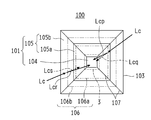
- FIG. 9B is a cross-sectional view of one condenser lens extracted from the cross-sectional state taken along arrows 9B-9B in FIG. 9A.
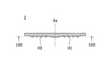
- FIG. 10B is a cross-sectional view of the condensing lens shown in FIG. 9A taken along the plane of arrows 10B-10B shown in FIG. 10A.
- FIG. 11B is a cross-sectional view of the condensing lens shown in FIG. 11A taken along the plane of the arrow 11B-11B shown in FIG. 11A. It is a perspective view which shows the shape of the secondary lens in Embodiment 3 in the state seen from diagonally upward. It is a side view which shows the state which looked at the secondary lens shown to FIG. 12A from the side surface.
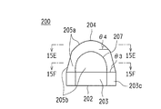
- FIG. 15B is a conceptual diagram conceptually showing the state of light collection and refraction when the light collected by the condenser lens is incident on the secondary lens at the position of the arrow 15E-15E shown in FIG. 15B. It is. Conceptual diagram conceptually showing the state of light collection and refraction when the light collected by the condenser lens is incident on the secondary lens at the position of the arrows 15F-15F shown in FIG. 15B. It is. It is a perspective view which shows the shape of a secondary comparison lens in the state seen from diagonally upward.
- FIG. 16C is a cross-sectional view showing a cross section of the secondary comparison lens at the position of arrows 16C-16C in FIG. 16B. It is a perspective view which shows the shape of the secondary lens in Embodiment 5 in the state seen from diagonally upward. It is a side view which shows the state which looked at the secondary lens shown to FIG. 17A from the side surface.
- FIG. 17B is a cross-sectional view showing a state of the outer peripheral shape of the secondary lens at the position of arrows 17C-17C shown in FIG. 17A.
- FIG. 18B is a cross-sectional view illustrating the concentrating solar power generation device and the concentrating solar power generation module illustrated in FIG. 18A in a cross-sectional state taken along arrows 18B-18B in FIG. 18A.
- FIG. 18B is a cross-sectional view illustrating the concentrating solar power generation device and the concentrating solar power generation module illustrated in FIG. 18A in a cross-sectional state taken along arrows 18B-18B in FIG. 18A.
- FIG. 1A and 1B are schematic views illustrating the configuration of a concentrating solar power generation module according to the present invention.
- FIG. 1A is a plan view seen from the incident surface of sunlight Lc
- FIG. It is a 1B line sectional view.
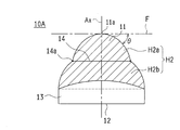
- 2A and 2B show the shape of the secondary lens according to Embodiment 1
- FIG. 2A is a side view
- FIG. 2B is a perspective view.
- the slanted line in FIG. 2A indicates the region of the optical refracting surface of the incident portion described later.
- the concentrating solar power generation module 20M is a concentrating solar in which the condensing lens 2 that is a primary optical system, the secondary lens 10A of the first embodiment that is a secondary optical system, and the solar battery cell 3 are arranged as a set.
- a plurality of photovoltaic power generation units (hereinafter also simply referred to as units) are arranged, and an appropriate number of individual solar cells are electrically connected in order to obtain necessary current and voltage. Yes.
- One unit has a size of several tens to several hundreds mm.
- the solar battery cell 3 is mounted on the receiver substrate 4.
- the holding plate 5 holds the receiver substrate 4 and faces the condenser lens 2.
- the solar cells 3 are arranged on the optical axis Ax of the condensing lens 2 (direction perpendicular to the condensing lens 2 that is the light receiving surface of the concentrating solar power generation module 20M, that is, the optical axis of the optical system) Ax. As shown, the condenser lens 2 and the holding plate 5 are held.
- the secondary lens 10 ⁇ / b> A is mounted on the upper center of the solar battery cell 3 and refracts the solar light Lc collected by the condenser lens 2 to irradiate the solar battery cell 3.
- the translucent filler 7 is filled between the solar battery cell 3 and the secondary lens 10A, and serves as a filling portion for fixing the solar battery cell 3, the receiver substrate 4 and the secondary lens 10A. That is, the secondary lens 10 ⁇ / b> A, the solar battery cell 3, the receiver substrate 4, and the translucent filler 7 constitute a solar battery package.
- the output cable 8 takes out the output of the solar battery cell 3.
- the light shielding plate 9 condenses the sunlight Lc by the condenser lens 2 and shields the collected sunlight (collected light beam) Lc from being irradiated to unnecessary places such as the output cable 8 and the receiver substrate 4. It is.
- Sunlight Lc enters from a direction parallel to the optical axis Ax, is refracted by the condensing lens 2, and is condensed toward the solar battery cell 3.
- the condensing lens 2 a surface that refracts so as to condense sunlight Lc toward the optical axis Ax is an optical refracting surface H1.
- the condensing lens 2 is a concentric Fresnel lens in the present embodiment in consideration of weight reduction due to thinning, reduction of material cost, improvement of condensing magnification, and molding processability.
- the condensing lens 2 is formed in a quadrangular shape, and four of them are arranged vertically and horizontally and held on the module frame 6.
- the material of the condenser lens 2 for example, a silicone resin is used.
- various light-transmitting materials can be used as the material of the condenser lens 2, and specifically, acrylic resin such as PMMA (polymethyl methacrylate resin), polycarbonate, glass, or the like is used. Can do.
- an inorganic solar cell made of Si, GaAs, CuInGaSe, CdTe or the like, or an organic solar cell such as a dye-sensitized solar cell is used.
- a single junction type cell, a monolithic multi-junction type cell, a mechanical stack cell in which various solar cells having different sensitivity regions are connected, or the like is used.
- a multi-junction solar cell for example, an InGaP / GaAs / Ge3 junction solar cell
- a mechanical stack cell is used.
- a three-junction solar cell is used.
- the secondary lens 10 ⁇ / b> A faces the condenser lens 2 and has an incident portion 11 having a first surface on which the collected light beam from the condenser lens 2 enters as incident light, and the condenser lens 2 facing the solar battery cell 3. 2, which has a second surface that emits the incident light of the collected light beam incident from the light source, the incident light to the incident portion 11 is emitted from the emission portion 12 and guided to the solar cell 3.
- the surface of the incident light that enters the incident portion 11 at this time is an optical refracting surface H2 (see FIG. 2A).
- the secondary lens 10 ⁇ / b> A is bonded and fixed integrally to the solar battery cell 3 and the receiver substrate 4 via the translucent filler 7 on the upper surface of the solar battery cell 3.
- the solar battery cell 3 and the receiver substrate 4 are bonded to the secondary lens 10A. Even when the translucent filler 7 adheres to the side surface of the secondary lens 10 ⁇ / b> A, that is, the intermediate region 13, the output characteristics of the solar battery cell 3 are not affected.
- the specific structure is not illustrated here, but a jig or other appropriate member is used. Even in such a case, they may be used in contact with the intermediate region 13. As a result, the manufacturing process of the concentrating solar power generation module can be simplified, and the concentrating solar power generation module can be assembled more inexpensively and reliably.
- secondary lens 10A what has a high transmittance
- glass, an acryl, a polycarbonate etc. are mentioned, these are mentioned. It is not limited to these, and it may be composed of a plurality of layers of these materials.
- a suitable ultraviolet absorber for the purpose of preventing the ultraviolet degradation of the material inside the concentrating solar power generation module and the ultraviolet degradation of the secondary lens 10A.
- an appropriate antireflection film or the like can be provided.
- the reflection loss on the surface of the secondary lens 10A can be reduced, the output of the solar battery cell 3 can be improved.
- a high refractive index material can be used as the material of the secondary lens 10A.
- the cross-sectional area in the direction perpendicular to the optical axis Ax of the incident portion 11 is from the condenser lens 2 side (upper side in FIGS. 2A and 2B) to the solar cell 3 side (FIGS. 2A and 2B).
- the inclination angle ⁇ of the optical refractive surface H2 of the incident portion 11 with respect to the surface F in the direction perpendicular to the optical axis Ax is increased from the condenser lens 2 side to the solar cell 3 side.
- Inflection point 14a (in other words, in plan view as viewed from the optical axis Ax direction) in which the inclination angle ⁇ decreases monotonically as the inclination angle ⁇ increases and the inclination angle ⁇ monotonously increases It is configured to have at least one variable curve 14) passing through the point 14a.
- the incident portion 11 has a shape in which substantially hemispherical bodies are stacked in two steps in the vertical direction (or a shape in which a halfway in the height direction of the substantially hemispherical body is narrowed inward by one step).
- the optical refracting surface of the incident portion 11 above the curve 14 is the first optical refracting surface H2a, and below the curve 14 (solar cell 3 side).
- the optical refracting surface of the incident part 11 is defined as a second optical refracting surface H2b.
- the first optical refracting surface H2a and the second optical refracting surface H2b have a circular cross section in a direction perpendicular to the optical axis Ax, and a cross section in a direction perpendicular to the optical axis Ax of the condenser lens 2. It is similar to the shape.
- the cross-sectional shape in the direction perpendicular to the optical axis Ax of the first optical refracting surface H2a and the second optical refracting surface H2b is taken as the cross-sectional shape in the direction perpendicular to the optical axis Ax of the optical refracting surface H1 of the condenser lens 2. It is possible to improve the light collection efficiency on the surface of the solar battery cell 3 by making it similar.
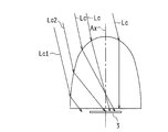
- FIG. 3A shows a sunlight collecting path when sunlight Lc collected by the collecting lens 2 enters the secondary lens 10A.
- FIG. 3B shows a sunlight condensing path when the secondary lens has a simple substantially hemispherical shape (dome shape) (hereinafter referred to as a secondary lens of a comparative example). ing.
- the secondary lens 10A of the first embodiment As shown in FIG. 3A, almost all of the sunlight Lc incident on the first optical refracting surface H2a reaches the surface of the solar battery cell 3, while the second optical refracting light.
- the sunlight Lc incident on the surface H2b has an inflection point because the sunlight Lc1 incident on the relatively outer side of the second optical refracting surface H2b is equivalent to the gentle inclination of the optical refracting surface near the inflection curve 14. Since it is incident on the secondary lens 10A at a position that is relatively high (condenser lens 2 side) as compared with the case where no solar cell is provided, it reaches the end of the solar battery cell 3. As a result, as shown in FIG.
- the sunlight Lc that reaches the surface of the solar cell 3 is the solar cell 3. Concentration is relaxed in the surface of the surface, and it reaches almost uniformly.
- the maximum value of the light intensity distribution when the secondary lens 10A of Embodiment 1 is used is slightly over 20.
- the sunlight Lc1 incident on the lens lower side corresponding to the second optical refracting surface H2b of Embodiment 1 has a sufficient incident surface height. Therefore, the optical path length cannot be secured and the solar battery cell 3 is not reached.
- the sunlight Lc2 incident on the lens surface corresponding to the vicinity of the lower part of the curve 14 also tends to be near the center of the optical axis. As a result, the light intensity distribution of the sunlight Lc reaching the surface of the solar battery cell 3 is shown in FIG. The central part of is high.
- the maximum value of the light intensity distribution when the secondary lens of the comparative example is used is slightly over 30. This tendency becomes more prominent when light in the middle to long wavelength region is collected when a multi-junction type (for example, three-junction type) solar cell is used as the solar cell 3. That is, by using the secondary lens 10A of the first embodiment, the maximum value of the light intensity distribution in the surface of the solar battery cell 3 can be reduced to about two thirds when the secondary lens of the comparative example is used. In addition, it can be seen that the sunlight Lc reaching the surface of the solar battery cell 3 can be distributed substantially uniformly within the surface.
- the entire secondary lens 10A is formed into a dome shape, and a step (inflection point 14a) whose inclination is reduced is provided in the middle of the dome shape in the height direction. It is possible to relax (disperse) the concentration of light collected on the surface of the solar cell 3 and to uniformly irradiate the surface of the solar battery cell 3 with light. That is, the power generation efficiency (conversion efficiency) of the solar battery cell 3 can be improved by using the secondary lens 10A of the present invention for the concentrating solar power generation module 20M.
- the inflection curve 14 passing through the inflection point 14a may be formed so as to be located outside the opposing solar battery cell 3 in a plan view viewed from the optical axis direction. desirable.
- the sunlight Lc1 incident on the relatively outside of the second optical refracting surface H2b. can reach the edge of the surface of the solar battery cell 3, so that the surface of the solar battery cell 3 can be irradiated with light uniformly.
- the cross-sectional shape in the direction perpendicular to the optical axis of the first optical refracting surface H2a which is the region from the top 11a of the secondary lens to the inflection point 14a (inflection curve 14).
- the cross-sectional shape in the direction perpendicular to the optical axis of the optical refracting surface H1 of the condenser lens 2 is similar. That is, in this embodiment, since the condensing lens 2 is a concentric Fresnel lens, the cross-sectional shape in the direction perpendicular to the optical axis of the optical refracting surface H1 of the condensing lens 2 is a circular shape. 10A also has a circular cross section in the direction perpendicular to the optical axis of the first optical refracting surface H2a.
- the cross-sectional shape of the first optical refracting surface H2a in the direction perpendicular to the optical axis Ax is made similar to the cross-sectional shape in the direction perpendicular to the optical axis Ax of the optical refracting surface H1 of the condenser lens 2.
- the concentration of the sunlight Lc collected on the surface of the solar battery cell 3 is relaxed (that is, the light once concentrated on the optical axis in the surface of the solar battery cell 3). And can be dispersed in the radial direction from the center). That is, it becomes possible to uniformly irradiate the surface of the solar cell 3 with more sunlight Lc by concentration and dispersion of light, and to improve the power generation efficiency (conversion efficiency) of the solar cell 3. it can.
- a solar cell 3 is a three-junction solar cell (for example, a three-junction solar cell of InGaP (top cell) / GaAs (middle cell) / Ge (bottom cell)).
- the inflection point is such that light in a wavelength region corresponding to a solar cell (top cell) having a sensitivity region on the short wavelength side among the three-junction solar cells does not enter the second optical refracting surface H2b.
- the formation position of 14a (curvature curve 14) is set.
- “so that light in the wavelength region corresponding to the top cell does not enter the second optical refracting surface H2b” means that it is configured as such in design and the actual use environment.
- the inflection point 14a (inflection curve 14) is formed at a position outside the range in which light in the short wavelength region is incident.
- the inflection point 14a is formed at a position outside the range in which light in the short wavelength region is incident.
- the first optical refracting surface H2a is incident on the first optical refracting surface H2a and is not incident on the second optical refracting surface H2b (strictly speaking, it hardly enters). Therefore, it is possible to efficiently collect light in the wavelength region incident on the top cell surface and irradiate the top cell with light.
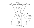
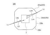
- FIG. 5A shows a light condensing path when light Lcs in a short wavelength region corresponding to the top cell is incident on the secondary lens 10A.
- the light Lcs in the short wavelength region corresponding to the top cell has a large wavelength dispersion and hits a wide range, in order to maintain the light collection efficiency (optical efficiency), the light is aimed at the center of the secondary lens 10. It needs to be collected and condensed.
- the concentration of the light Lcs in the short wavelength region incident on the surface of the top cell is alleviated, and the top cell Therefore, the light collection efficiency (conversion efficiency) of the light Lcs in the short wavelength region corresponding to the top cell can be improved.
- the secondary lens 10A of the first embodiment after light of a specific wavelength incident on the first optical refracting surface H2a near the upper part (near the boundary) of the inflection point 14a (inflection curve 14) intersects the optical axis Ax.
- the sun Before reaching the solar cell 3 and light having a specific wavelength incident on the second optical refracting surface H2b near the lower part (near the boundary) of the inflection point 14a (the inflection curve 14) crosses the optical axis Ax, the sun
- the inclination angle of the first optical refracting surface H2a and the second optical refracting surface H2b and the height position of the inflection point 14a (inflection curve 14) are set so as to reach the battery cell 3.
- the specific wavelength can be, for example, a medium wavelength region of 650 to 900 nm corresponding to the middle cell.
- FIG. 5B shows a light condensing path when light Lcm in the medium wavelength region corresponding to the middle cell is incident on the secondary lens 10A.
- the light Lcm in the middle wavelength region is irradiated in a relatively narrow range. Further, since the refraction angle at the condenser lens 2 is smaller than the light in the short wavelength region, the light is condensed outside the short wavelength region. For this reason, the secondary lens 10A is provided by providing an inflection point 14a (inflection curve 14) and making the inclination angle of the optical refracting surface outside the inflection curve 14 (that is, the second optical refracting surface H2b) gentle. The light Lcm in the medium wavelength region incident on the outer side farther than the optical axis Ax can be efficiently condensed on the middle cell surface.
- the traveling direction of the light after incidence before and after the height direction of the inflection point 14a does not cross the direction crossing the optical axis Ax (light Lcm1).
- Dispersing in the direction (light Lcm2) uniformly irradiates the middle cell surface with light in the middle wavelength region, so that the middle cell conversion efficiency (output power) can be improved.
- the distance D1 from the inflection point 14a (inflection curve 14) to the solar battery cell 3 is the distance D2 from the apex of the secondary lens 10A to the surface of the solar battery cell 3. It is set to be more than half.
- the light collection efficiency is improved by setting the distance D1 from the inflection point 14a to the surface of the solar battery cell 3 to be half or more of the distance D2 from the top of the secondary lens 10A to the surface of the solar battery cell 3.
- An inflection point 14a (inflection curve 14) can be provided on the near side (vertex side) that decreases.
- FIG. 6 is a chart showing the simulation results of the light collection efficiency when the distance D1 is set to a half or more of the distance D2, and when the distance D1 is set to a half or less.
- the result 1 is when the distance D1 is more than half of the distance D2 (in this example, the distance D1 is 63% of the distance D2), and the result 2 is when the distance D1 is less than half of the distance D2 (this In the example, the simulation result is shown in a case where the distance D1 is 49% of the distance D2.
- the lens diameter of the condenser lens 2 is 170 mm square
- the height of the secondary lens 10A is 11.4 mm
- the diameter of the emitting portion 12 of the secondary lens 10A is 14.4 mm ⁇
- the diameter of the solar battery cell is: It was set to 4.5 mm square.
- the light intensity distribution is approximately uniform at about 20 on the top cell surface, the light intensity distribution is approximately uniform at about 25 on the middle cell surface, and the light intensity distribution on the bottom cell surface. Is approximately uniformly distributed at about 30.
- the light intensity distribution is almost uniform on the top cell surface with about 20, but the light intensity distribution is about 25 on the middle cell surface with more unevenness than the result 1. And, there is a tendency to concentrate slightly in the center. Further, on the surface of the bottom cell, the light intensity distribution is about 40, which is more uneven than the result 1, and further tends to concentrate in the center.
- the result 2 has a light condensing efficiency of 98.4% compared to the result 1 (however, the same applies below when the light condensing efficiency in the result 1 is 100%).
- the result 2 is slightly lower than the result 1 in the light collection efficiency of 95.6%.
- the result 2 is lower than the result 1 in the light collection efficiency of 91.1%. .
- the secondary lens of the result 1 has higher light collection efficiency in all the cells than the secondary lens of the result 2. Considering the actual usage situation, it can be said that the effect of the secondary lens of the present invention is obtained on a practical basis even with the light collection efficiency of Result 2.
- the light collection efficiency can be sufficiently improved on a practical basis by setting the distance D1 to be more than half of the distance D2. That is, the height position of the inflection point 14a (inflection curve 14) formed on the secondary lens 10A is such that the distance D1 from the inflection point 14a to the surface of the solar battery cell 3 is from the apex of the secondary lens 10A to the solar battery. It is preferable to form it at a height position that is at least half the distance D2 to the surface of the cell 3.
- Embodiment 2 of the secondary lens will be described.
- FIG. 7A to 7D show the shape of the secondary lens 10B of the second embodiment
- FIG. 7A is a perspective view
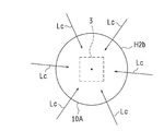
- FIG. 7B is a plan view
- FIG. 7C is a side view seen from the arrow X1 direction in FIG. These are the side views seen from arrow X2 direction of FIG. 7A.
- the difference between the secondary lens 10B of the second embodiment and the secondary lens 10A of the first embodiment is that, in the secondary lens 10B of the second embodiment, chamfered portions 16 are further formed at four locations around the second optical refractive surface H2b. This is the point. Therefore, in the secondary lens 10B of Embodiment 2, the cross-sectional shape in the direction perpendicular to the optical axis of the second optical refracting surface H2b of the secondary lens 10B is perpendicular to the optical axis of the optical refracting surface H1 of the condenser lens 2. It is dissimilar to the sectional shape of the direction.
- the condensing lens 2 is a concentric Fresnel lens
- the cross-sectional shape in the direction perpendicular to the optical axis of the optical refractive surface H1 of the condensing lens 2 is circular
- the second optical refracting surface H2b of the secondary lens 10B has a chamfered portion 16 formed at four locations around the second optical refracting surface H2b. .
- Embodiment 1 As shown in FIG. 8A, the sunlight Lc incident on the second optical refracting surface H2b travels straight toward the optical center P in plan view, but in Embodiment 2, FIG. 8B As shown in FIG. 4, the sunlight Lc incident on the chamfered portion 16 is refracted away from the optical axis center P in a plan view, and is dispersed and incident so as to spread from the optical axis center P. As a result, the sunlight Lc reaches the surface of the solar battery cell 3 in a dispersed manner.
- the above-described effect (that is, the inflection point 14a (inflection curve 14)) of the secondary lens 10A of the first embodiment is provided, so that the light enters the second optical refractive surface H2b.
- the chamfered portion 16 which is a non-similar part Since the sunlight Lc incident on the solar cell 3 can be further refracted in the horizontal direction in a plan view, the effect of dispersion and concentration relaxation of the sunlight Lc incident on the surface of the solar battery cell 3 can be obtained. It becomes possible to irradiate the solar cell surface more uniformly with sunlight Lc. As a result, the power generation efficiency (conversion efficiency) of the solar battery cell 3 can be further improved.
- a secondary lens having a cross-sectional shape in a direction perpendicular to the optical axis of the second optical refracting surface of the secondary lens and a cross-sectional shape in a direction perpendicular to the optical axis of the optical refracting surface of the condenser lens are not similar.
- the shape is not limited to the shape of the secondary lens 10 ⁇ / b> B of Embodiment 2 (a shape that simply chamfers the four surroundings), and various shapes can be used in consideration of the cross-sectional shape of the condenser lens 2. can do.
- the cross-sectional shape of the optical refracting surface of the condensing lens is a quadrangle
- the cross-sectional shape of the secondary lens may be the same circular shape as in the first embodiment.
- the solar cell mounting body is filled with the translucent filler 7 between the secondary lens 10 and the solar battery cell 3, so that the secondary lens.
- the air layer between 10A, 10B and the photovoltaic cell 3 is excluded.
- FIG. 9A is a plan view showing the concentrating solar power generation device 30 and the concentrating solar power generation module 30M according to Embodiment 3 of the present invention as viewed from the condensing lens 2 side.
- FIG. 9B is a cross-sectional view showing the concentrating solar power generation device 30 and the concentrating solar power generation module 30M shown in FIG. 9A in a cross-sectional state taken along arrows 9B-9B in FIG. 9A.
- the hatching which shows a cross section is given partially in consideration of the legibility of the drawings.
- the concentrating solar power generation device 30 includes a condensing lens 2 and a solar battery cell 3 that are primary lenses.
- the receiver substrate 4 has the solar battery cell 3 mounted thereon.
- the holding plate 5 holds the receiver substrate 4 and faces the condenser lens 2.
- the module frame 6 has a condensing lens 2 and a holding plate so as to form a vertical axis Ax defined by the center (surface center) 2c of the condensing lens 2 and the center (light receiving surface center) 3c of the solar battery cell 3. 5 is connected.
- the secondary lens 100 faces the solar battery cell 3 and is bonded and fixed to the solar battery cell 3 and the receiver substrate 4 via the translucent material filling portion 7.
- the secondary lens 100 is arranged facing the solar battery cell 3, and refracts the light Lc (usually specifically sunlight) collected by the condenser lens 2 to irradiate the solar battery cell 3. .
- the secondary lens 100, the solar battery cell 3, the receiver substrate 4, and the translucent material filling unit 7 constitute the solar battery package 1.
- the concentrating solar power generation device 30 has a working distance Wd (work distance) as an interval between the condensing lens 2 and the solar battery cell 3.
- the translucent material filling unit 7 is formed of a translucent material filled between the solar battery cell 3 and the secondary lens 100, and the solar battery cell 3 is interposed between the receiver substrate 4 and the secondary lens 100. Seal.
- the output cable 8 is connected to the solar battery cell 3 and takes out the output of the solar battery cell 3.
- the light shielding plate 9 shields a member disposed around the solar battery cell 3 and protects a member (such as the output cable 8) that may be damaged by the irradiation of the light Lc collected by the condenser lens 2. .
- the solar battery cell 3 is preferably a three-junction compound solar battery with high power generation efficiency.
- the present invention is not limited to this, and the solar battery cell 3 may be a single-crystal or polycrystalline silicon solar battery cell, a multi-junction type compound solar battery other than three junctions, or the like.
- the condensing lens 2 has an optical refracting surface H1 that refracts the light Lc toward the secondary lens 100 disposed on the vertical axis Ax so as to condense the light Lc.
- the vertical axis Ax coincides with the optical axis of the condenser lens 2.
- the vertical axis Ax including the optical axis of the condenser lens 2 is simply used.
- the condenser lens 2 is formed of, for example, a silicone resin.
- the refractive index n varies depending on the lens temperature.
- the refractive index nD (D-line refractive index, that is, the refractive index for light having a wavelength of 589 nm) is 1.412 at a temperature of 20 ° C. and 1.405 at a temperature of 40 ° C.
- the condenser lens 2 is an imaging lens having a focal length of 230 mm
- the focal position is reached at a lens temperature of 20 ° C., for example, from a position 100 mm away from the center 2c of the condenser lens 2 in a direction perpendicular to the vertical axis Ax.
- the light having a wavelength of 589 nm is focused at a position of 236 mm from the condenser lens 2 when the lens temperature is 40 ° C., and 2.2 in the direction perpendicular to the vertical axis Ax at the position of 230 mm from the condenser lens 2. It will pass through a position 6 mm away. Since similar aberrations occur for all wavelengths, as a result, the diameter of the collected light beam (the bundle of light formed by the collected light Lc) varies with the variation of the lens temperature, and the solar battery cell 3 Affects the output characteristics.
- the secondary lens 100 is disposed so as to face the solar battery cell 3, the variation in the diameter of the collected light beam accompanying the change in temperature (optical characteristics) of the condenser lens 2 is absorbed. Can do. Therefore, the shape of the optical characteristics (lens shape) of the secondary lens 100 is directly related to the power generation efficiency (photoelectric conversion efficiency) of the concentrating solar power generation device 30, and the basics of the present embodiment. Configuration requirements.
- the silicone resin was illustrated as a material of the condensing lens 2, various translucent materials can be used for the material of the condensing lens 2, for example, PMMA (polymethyl methacrylate resin) etc.
- PMMA polymethyl methacrylate resin
- An acrylic resin, polycarbonate, glass, or the like can be used. Of these, glass is often not used from the viewpoint of workability.
- a resin material such as PMMA which is excellent in processability, has a problem that the temperature dependency of the refractive index is large as in the case of a silicone resin.
- the condensing lens 2 is a Fresnel lens having saw teeth formed concentrically from the viewpoint of weight reduction by thinning, reduction of material cost, improvement of condensing magnification, processability of molding, and the like. Although a Fresnel lens is illustrated, as long as the light Lc can be condensed toward the secondary lens 100, a lens having another shape can be applied.
- the condenser lens 2 is formed in a quadrangular outer periphery (outer frame), and the side dimension of one side is L1.
- the module frame 6 holds four condensing lenses 2 side by side in the vertical and horizontal directions, for a total of four.
- the secondary lens 100, the solar battery cell 3, and the receiver substrate 4 are provided corresponding to each condenser lens 2 and are held by a common holding plate 5.
- the four condensing lenses 2 (the concentrating solar power generation device 30) are gathered together so as to face the holding plate 5 and the module frame 6. That is, the concentrating solar power generation module 30M according to the present embodiment is configured to include four concentrating solar power generation devices 30.
- the shape (optical characteristics) of the secondary lens 100 is defined in relation to the shape (optical characteristics) of the condenser lens 2, a specific example of the condenser lens 2 applied to the third embodiment will be described.
- FIG. 10A is a cross-sectional view of one condenser lens 2 extracted from the cross-sectional state taken along arrows 9B-9B in FIG. 9A.
- FIG. 10B is a cross-sectional view of the condenser lens 2 shown in FIG. 9A taken along the plane of arrows 10B-10B shown in FIG. 10A.
- the condensing lens 2 condenses the light Lc toward the secondary lens 100 and the solar battery cell 3 arranged on the vertical axis Ax.
- the condensing lens 2 is a Fresnel lens, and sawtooth teeth of the Fresnel lens are concentrically formed to condense the light Lc.
- the condenser lens 2 may be either an imaging type or a non-imaging type.
- the optical refracting surface H1 that defines the condensing characteristic of the condensing lens 2 and the vertical axis Ax that affects the shape (optical characteristic) of the secondary lens 100.
- the optical refractive surface H1 of the condenser lens 2 is cut by a plane (arrow 10B-10B) perpendicular to the vertical axis Ax, an edge that appears as an edge of a cross section (hatched figure: annular figure in FIG. 10B)
- a similar shape (various circular shapes having different radii) of the shape 2e is compared with the shape of the secondary lens 100. That is, the relationship between the similar shape of the edge shape 2e and the shape of the secondary lens 100 is one of the components of the present invention.
- FIG. 11A is a cross-sectional view in a plane including the vertical axis Ax in the condensing lens 2s having a shape different from that of the condensing lens 2 in FIG. 10A.
- FIG. 11B is a cross-sectional view of the condensing lens 2s shown in FIG. 11A taken along the plane of the arrow 11B-11B shown in FIG. 11A.
- the condensing lens 2s is a convex lens that is convex toward the solar cell 3 side. This type of condensing lens 2s can also condense the light Lc toward the secondary lens 100 and the solar battery cell 3 arranged on the vertical axis Ax. Therefore, what is to be compared with respect to the shape of the secondary lens 100 is a diagram representing the relationship between the optical refracting surface H1s that defines the condensing characteristic of the condensing lens 2s and the vertical axis Ax. .
- the optical refractive surfaces H1 and H1s are perpendicular to the vertical axis Ax.
- Edge shapes 2e and 2se appearing as edges of a cross section (annular figure in FIG. 10B, circular figure in FIG. 11B) when cut along a plane (arrow 10B-10B in FIG. 10A, arrow 11B-11B in FIG. 11A) are circles (Or concentric circles).
- the shape of the condensing lenses 2 and 2s is not limited to this, and may be any shape that can condense light toward the vertical axis Ax, and is not limited to the above-described circle.
- edge shapes edge shapes 2e and 2se
- the converging lenses 2 and 2s and the secondary lens 100 have different relative sizes, and thus have optical characteristics (compared to each other).
- the outer peripheral shape 106 see FIG. 12D in the cross section of the secondary lens 100 and the condenser lens This is to show that the edge shapes 2e and 2se in the cross section of 2 and 2s are different from the similar shape.
- the reason why the outer peripheral shape of at least a part of the cross section of the secondary lens 100 is different from the similar shape of the edge shape (edge shape 2e, 2se) is that the secondary lens 100 in a plan view (in the direction of the vertical axis Ax). This is because the surface of the secondary lens 100 is inclined with respect to the traveling direction of the light Lc, and the light Lc can be refracted.
- the edge of the cross section obtained by cutting the optical refracting surfaces (H1, H1s) of the condenser lens (2, 2s) by a plane perpendicular to the vertical axis Ax (arrow 10B-10B in FIG. 10A, arrow 11B-11B in FIG. 11A)
- the shape (2e, 2se) is a circle (edge shape 2e) extracted from a plurality of concentric circles around the vertical axis Ax in the case of a Fresnel lens (FIG. 10A) in which a plurality of optical refracting surfaces H1 are annularly arranged.
- a lens FIG.
- edge shape 2se having a single convex refractive surface on at least one side, it is a single circle (edge shape 2se).
- the optical refractive surface H1 and the optical refractive surface H1s are simply referred to as the optical refractive surface H1 without particular distinction.
- the edge shape 2e and the edge shape 2es are not particularly distinguished from each other and are simply referred to as the edge shape 2e.
- FIG. 12A is a perspective view showing the shape of the secondary lens 100 in Embodiment 3 as viewed obliquely from above.
- FIG. 12B is a side view showing the secondary lens 100 shown in FIG. 12A as viewed from the side.
- the secondary lens 100 is disposed to face the condenser lens 2, and is disposed to face the solar cell 3 and the incident portion 101 on which the light Lc (incident light) collected by the condenser lens 2 is incident. And an emitting unit 102 that emits the light Lc incident on the incident unit 101 to the solar battery cell 3. That is, the secondary lens 100 guides the incident light (light Lc) incident on the incident part 101 to the emission part 102 and irradiates the emitted light (light Lc) from the emission part 102 to the solar cell 3.
- the secondary lens 100 includes a base portion 103 serving as a light guide between the incident portion 101 and the emission portion 102.
- the incident portion 101, the emitting portion 102, and the base portion 103 are integrally formed to realize the optical characteristics as the secondary lens 100 with high accuracy.
- the incident part 101 includes a top part 104 that faces the condenser lens 2, an intermediate part 105 a that is arranged (formed) following the top part 104, and an intermediate part that is arranged (formed) after the intermediate part 105 a and faces the emitting part 102.
- Part 105b that is, the intermediate part 105a and the intermediate part 105b constitute an intermediate part 105 that is positioned between the top part 104 and the emitting part 102 and into which the light Lc is incident.
- the intermediate portion 105 a and the intermediate portion 105 b may be simply referred to as the intermediate portion 105 when it is not necessary to distinguish between them.
- the emission part 102 has a planar shape facing the solar battery cell 3.
- the base portion 103 has a substantially quadrangular shape corresponding to the chip shape of the solar battery cell 3, and the intermediate portion 105 b is a quadrangular pyramid because it is continuously arranged with respect to the base portion 103.
- the surface 105b is composed of four planes (refractive surfaces). Since the intermediate portion 105a is continuously arranged with respect to the intermediate portion 105b, it is a quadrangular pyramid like the intermediate portion 105b, and the surface of the intermediate portion 105a is configured by four planes (refractive surfaces).
- the upper end of the intermediate part 105a becomes the top part 104 as it is, and the top part 104 is a square. That is, the upper end of the intermediate portion 105 a (square pyramid) is the top portion 104, the lower end of the intermediate portion 105 a coincides with the upper end of the intermediate portion 105 b, and the lower end of the intermediate portion 105 b coincides with the base portion 103. Further, the lower end of the base part 103 constitutes the emission part 102.
- the secondary lens 100 has a mountain-shaped three-dimensional shape having one apex with respect to the emission part 102. That is, the intermediate portion 105 has a cross-sectional area in a direction perpendicular to a straight line passing through the center 102 c of the emission portion 102 and the center 104 c of the top portion 104 (usually coincides with the vertical axis Ax) from the top portion 104 to the emission portion 102.
- the shape increases as it approaches. With this structure, the light Lc can be refracted or condensed toward the solar battery cell 3.
- the vertical axis Ax defined by the center 2 c of the condenser lens 2 and the center 3 c of the solar battery cell 3 is substantially relative to a straight line passing through the center 102 c of the emitting portion 102 and the center 104 c of the top portion 104 in the secondary lens 100. In the following, it is simply referred to as the vertical axis Ax.
- the vertical axis Ax may deviate from the center 102 c of the emission part 102 and the center 104 c of the top part 104 depending on the overall shape of the secondary lens 100.
- the secondary lens 100 is generally aligned with respect to the vertical axis Ax as a whole, in the following, the straight line passing through the vertical axis Ax and the center 102c of the emitting portion 102 and the center 104c of the top portion 104 is It demonstrates as what is substantially in agreement. Even if there is some displacement, the action is the same.
- the base 103 is configured not to have a lens function. That is, the base 103 is a light guide that simply guides the light Lc from the incident part 101 to the emission part 102 without refracting or dispersing the light Lc. Therefore, when the receiver substrate 4 on which the solar battery cell 3 is mounted and the secondary lens 100 are bonded and fixed, the translucent material of the translucent material filling unit 7 is used as the base unit 103. Even if it adheres to the outer peripheral surface, the output characteristics of the solar cells 3 are not affected at all.
- the secondary lens 100 (a straight line passing through the center 102c of the emitting portion 102 and the center 104c of the top portion 104) is aligned with the vertical axis Ax (the condensing lens 2 and the solar battery cell 3), a jig or the like
- An appropriate member can be brought into contact with the outer peripheral surface (side surface) of the base portion 103 and handled accurately. Therefore, the base part 103 can simplify the manufacturing process of the concentrating solar power generation device 30, and more reliably and cheaply the concentrating solar power generation device 30 (the concentrating solar power generation module 30 ⁇ / b> M). ) Can be assembled.
- the intermediate part 105 has a ridge part 107 since the intermediate part 105a and the intermediate part 105b are formed of a quadrangular frustum. The chamfering on the ridgeline portion 107 will be described later.
- FIG. 12C is a conceptual diagram conceptually showing the state of light collection and refraction when the light Lc collected by the condenser lens 2 is incident on the secondary lens 100 as seen from the lateral direction.
- FIG. 12D is a conceptual diagram conceptually showing the state of light condensing and refraction when the light Lc condensed by the condensing lens 2 is incident on the secondary lens 100 when viewed from the direction of the vertical axis Ax.
- the lens width L3 of the secondary lens 100 (the lower end of the incident portion 101 (intermediate portion 105b), the base portion 103), that is, the length of one side of the quadrangle, is the chip size of the solar cell 3, that is, the length L2 of one side of the chip. It is set to be larger than the cell dimension L2), and the light Lc can be guided (irradiated) to the entire solar cell 3 (light receiving surface of the cell).
- the light Lcs that does not originally reach the solar battery cell 3 is also refracted again by the secondary lens 100 (intermediate portion 105 b of the incident portion 101).
- the shape of the incident part 101 is determined so that the solar battery cell 3 can be reached.
- the light Lcs of the light Lc collected by the condenser lens 2 goes straight ahead and deviates from the solar battery cell 3.
- the secondary lens 100 since the secondary lens 100 is disposed, the light Lcs reaches the solar cell 3 as light Lcr by the refraction action in the intermediate portion 105b whose surface is flat, and contributes to photoelectric conversion.
- the light Lcq assumed to travel straight toward the solar battery cell 3 is applied to the solar battery cell 3 as a light Lcp at a position shifted from the light Lcq by the refraction action in the intermediate portion 105a.
- the intermediate portion 105 (secondary lens 100) is disposed, the light Lc traveling toward the solar battery cell 3 is refracted again on the surface of the incident portion 101 (intermediate portion 105), and the vertical axis Ax.
- refraction in the direction along the axis (FIG. 12C)
- refraction in a plan view that appears when projected onto a plane perpendicular to the axis ( 12D, refraction (lateral refraction) that suppresses the concentration of light occurs in a plane that intersects the vertical axis Ax. Therefore, the light Lc collected toward the solar battery cell 3 is suppressed from being excessively concentrated near the center of the solar battery cell 3.
- the outer shape of the secondary lens 100 that refracts the light Lc and the action based on the outer shape will be further described.
- the outer peripheral shape 106a in the cross section in the direction perpendicular to the vertical axis Ax can be extracted. Since the outer peripheral shape 106a (including the surface) is oblique to the light Lc, the light Lc is refracted. Further, at the position where the light Lcr of the intermediate portion 105 (intermediate portion 105b) is refracted, the outer peripheral shape 106b in the cross section in the direction perpendicular to the vertical axis Ax can be extracted. Since the outer peripheral shape 106b (including the surface) is oblique to the light Lc, the light Lc is refracted. In the following, the outer peripheral shape 106 a and the outer peripheral shape 106 b may be simply referred to as the outer peripheral shape 106 when it is not necessary to distinguish between them.
- the outer peripheral shape 106 (square) is different from the similar shape (circle) of the edge shape 2e (circle) of the cross section obtained by cutting the optical refracting surface H1 of the condenser lens 2 along a plane perpendicular to the vertical axis Ax. Therefore, the light Lc collected toward the vertical axis Ax can be refracted, and the light Lc can be prevented from being extremely concentrated on the central portion of the solar battery cell 3.
- the inclination of the surface of the intermediate portion 105 is larger on the side closer to the emitting portion 102 (intermediate portion 105b) than on the side closer to the top portion 104 (intermediate portion 105a).
- the secondary lens 100 has a steeper slope of the surface of the intermediate part 105b on the side farther from the vertical axis Ax than the slope of the surface of the intermediate part 105a on the side closer to the vertical axis Ax.
- the steeper angle of the light Lc (light Lcs) collected at a position far from the center of the solar cell 3 (light receiving surface) toward the solar cell 3 in the direction along the vertical axis Ax. Since the light is refracted, the light collection efficiency is improved.
- the focal position is changed in the vertical axis Ax direction. Concentration of the light Lc can be reduced.
- the surface has a fixed inclination angle.
- the inclination (surface inclination angle) of the surface of the intermediate portion 105 can define the degree of inclination (sudden) by the angle between the surface of the intermediate portion 105 and a plane perpendicular to the vertical axis Ax.
- the first inclination angle ⁇ 1 (first inclination angle ⁇ 1 ⁇ 90 degrees), which is the surface inclination angle of the intermediate portion 105b on the side close to the emitting portion 102, is the surface inclination angle of the intermediate portion 105a on the side close to the top portion 104.
- the shape is larger than the second inclination angle ⁇ 2. That is, since the first inclination angle ⁇ 1 is larger than the second inclination angle ⁇ 2, the light Lc that reaches a position far from the solar battery cell 3 without the secondary lens 100 is refracted at a steeper angle to collect light. To improve.
- the secondary lens 100 includes the solar cell 3 and the concentrating solar power generation device including the condensing lens 2 that condenses the light Lc and irradiates the solar cell 3.
- 30 includes a light incident part 101 on which light Lc is incident and a light emitting part 102 that emits light Lc incident on the light incident part 101 to the solar battery cell 3.
- the incident part 101 includes a top part 104 facing the condenser lens 2 and an intermediate part 105 located between the top part 104 and the emitting part 102.
- the intermediate part 105 includes the center 2c of the condenser lens 2 and the intermediate part 105.
- the area of the cross section in a direction perpendicular to the vertical axis Ax defined by a straight line passing through the center 3c of the solar battery cell 3 increases as the distance from the top 104 toward the emission section 102 increases, and the outer periphery of at least a part of the cross section
- the shape 106 is a shape different from the similar shape of the edge shape 2e of the cross section obtained by cutting the optical refractive surface H1 of the condenser lens 2 along a plane perpendicular to the vertical axis Ax.
- the secondary lens 100 includes an intermediate portion 105 (intermediate portion in a direction perpendicular to a vertical axis Ax defined by a straight line passing through the center 2c of the condenser lens 2 and the center 3c of the solar battery cell 3.
- the cross sectional area of the portions 105a and 105b) increases (monotonically increases) from the top 104 to the emitting portion 102, and at least a part of the outer peripheral shape 106 (the outer peripheral shape 106a and the outer peripheral shape 106b) of the cross section is a condensing lens.
- the outer peripheral shape 106 is preferably a polygon. Accordingly, since the outer peripheral shape 106 is a polygon, the secondary lens 100 can refract much of the collected light Lc at each side of the polygon, so that the condensing is surely reduced. Further lowering of FF is suppressed.
- the polygon in the outer peripheral shape 106 is preferably a regular polygon.
- a hexagonal shape, an octagonal shape, or the like can be used.
- the surface of the intermediate portion 105 may be provided with at least a flat surface. That is, in the secondary lens 100, it is preferable that at least a part of the surface of the intermediate portion 105 is a flat surface. With this configuration, since the surface of the intermediate portion 105 has a flat surface, the secondary lens 100 has a cross-section of the condenser lens 2 obtained by cutting the outer peripheral shape 106 in the cross section of the intermediate portion 105 along a plane perpendicular to the vertical axis Ax. The shape can be different from the similar shape to the edge shape 2e.
- the ridgeline portion 107 appearing on the surface of the intermediate portion 105 can be appropriately chamfered, and the polygon in that case can be grasped as a pseudopolygon, and such a pseudopolygon is also implemented in the present embodiment.
- the polygon in the form of As the chamfering, C chamfering, R chamfering, or the like can be applied.
- the surface of the intermediate portion 105 has a ridge line portion 107, and the ridge line portion 107 is chamfered.
- the secondary lens 100 is chamfered with respect to the ridgeline of the intermediate portion 105, optical loss due to light scattering at the ridgeline portion 107 can be avoided, and in the production process. It is possible to prevent the occurrence of damage (chipping such as cracking and chipping) during handling.
- the inclination of the surface of the intermediate portion 105 is preferably larger on the side closer to the emitting portion 102 (intermediate portion 105b) than on the side closer to the top portion 104 (intermediate portion 105a).
- the secondary lens 100 has a greater inclination of the intermediate portion 105 (intermediate portion 105b) on the emission portion 102 side than the inclination of the intermediate portion 105 (intermediate portion 105a) on the top portion 104 side.
- the light Lc that reaches a position far from the center of the solar cell 3 (light receiving surface) is refracted toward the solar cell 3 in a direction along the vertical axis Ax at a steeper angle. Increase efficiency.
- the focal position is in the vertical axis Ax direction.
- concentration of the light Lc in the vertical axis Ax direction can be reduced.
- the definition of the tilt angle is as described above.
- the first inclination angle ⁇ 1 that is the surface inclination angle on the side close to the emission part 102 (intermediate part 105b) is the second inclination angle that is the surface inclination angle on the side close to the top part 104 (intermediate part 105a). It is preferable that it is larger than ⁇ 2.
- the secondary lens 100 has the first inclination angle ⁇ 1 on the surface on the emitting portion 102 side (intermediate portion 105b) in the intermediate portion 105 on the surface on the top portion 104 side (intermediate portion 105a) in the intermediate portion 105.
- the inclination angle ⁇ 2 is larger than the inclination angle ⁇ 2, the light Lc (light Lcs) reaching the position far from the solar battery cell 3 is refracted at a steeper angle when the secondary lens 100 is not provided, thereby improving the light collection efficiency. be able to.
- the top 104 of the secondary lens 100 is preferably a flat surface.
- the secondary lens 100 reliably guides the light Lc collected toward the solar battery cell 3 to the solar battery cell 3 without being excessively refracted because the top 104 is flat.
- the light collection efficiency can be improved, and the concentration of the light Lc due to the lens effect as the secondary lens 100 can be suppressed, so that the decrease in FF is further suppressed.
- the top 104 of the secondary lens 100 may be a convex curved surface instead of a flat surface.
- the secondary lens 100 since the secondary lens 100 has a curved top portion 104, the light Lc condensed on the top portion 104 by the condensing lens 2 can be efficiently reflected in the sun while the concentration of the light Lc as a whole is relaxed. Since the light is guided to the battery cell 3, the power generation amount of the solar battery cell 3 can be reduced by suppressing the decrease in the output current due to the angular deviation of the incident light Lc, the positional deviation of the solar battery cell 3 and the like. Can be increased.
- the secondary lens 100 includes a base portion 103 that is disposed between the emitting portion 102 and the intermediate portion 105 and integrated with the intermediate portion 105.
- the secondary lens 100 includes the base portion 103 that is disposed between the emitting portion 102 and the intermediate portion 105 and integrated with the intermediate portion 105. Since the secondary lens 100 can be handled, the handling and molding in the manufacturing process can be facilitated without impairing the optical characteristics of the secondary lens 100, the manufacturing process can be streamlined, the production efficiency can be improved, and the member cost can be reduced. Can be reduced.
- the outer periphery of the emission part 102 and the base part 103 of the secondary lens 100 is a quadrangle.
- the secondary lens 100 can be manufactured by efficiently arranging a large number in the manufacturing process. It is possible to improve the production efficiency in mold forming and reduce the member cost.
- the quadrangle in the emission part 102 and the base part 103 does not need to be a perfect quadrangle, and may be a substantially quadrangle with chamfering.
- the height of the base portion 103 of the secondary lens 100 is preferably 0.5 mm or more.
- the secondary lens 100 has the height of the base portion 103 (the length between the base portion 103 side of the intermediate portion 105 and the emitting portion 102 (the thickness of the base portion 103)) of 0. Since a certain thickness is secured because the thickness is 5 mm or more, defects such as chipping (chips) are hardly caused by handling with a jig.
- the secondary lens 100 is made to oppose the photovoltaic cell 3 through a translucent material (translucent material filling part 7), when a translucent material adheres to a side surface (base part 103). However, no optical loss occurs.
- the upper limit of the height of the base portion 103 is set to an appropriate value in consideration of loss as a light guide, workability (handling property), restriction on the dimension between the emitting portion 102 and the top portion 104, and the like. .
- the secondary condensing distance Dd May satisfy a predetermined condition defined in the concentrating solar power generation device 30.
- the incident portion 101 of the secondary lens 100 preferably includes an antireflection film on the surface.
- the secondary lens 100 since the secondary lens 100 includes the antireflection film on the surface of the incident portion 101, it is possible to suppress the reflected light Lc from being reflected on the surface and to reduce the loss due to the surface reflection. Therefore, the output of the solar battery cell 3 is improved.
- an antireflection film is provided on the surface, a lens material having a high refractive index (for example, a refractive index of 1.80 or more) can be applied.
- the secondary lens 100 is made of a light-transmitting optical material, and the light-transmitting optical material has a refractive index nD with respect to the D line (589.3 nm) of greater than 1.35 and less than 1.80.
- the absolute value of the temperature dependence of the rate is preferably less than 1 ⁇ 10 ⁇ 4 .
- the secondary lens 100 has a refractive index in the range of 1.35 to 1.80, the effect of the secondary lens 100 as a refractive element is ensured, and the reflectance of the surface is suppressed to collect light. Light efficiency can be maintained high, and even when refractive index fluctuations occur due to temperature rise due to light collection, fluctuations in light collection characteristics can be suppressed, ensuring stable optical characteristics and maintaining high efficiency. can do.
- the material of the secondary lens 100 for example, borosilicate glass (typically, BK7 manufactured by Schott) can be used.
- the material of the secondary lens 100 is not limited to borosilicate glass, and an appropriate translucent material can be used. Specifically, it is possible to use other optical glass such as silicone resin or quartz glass. However, if the refractive index is low, a sufficient lens effect cannot be obtained. Loss due to surface reflection when incident on 100 increases.
- the secondary lens 100 is made of a material having a refractive index nD of 1.35, the refraction angle is about 10% smaller than that of BK7, so that the lens effect is small.
- the ratio at which the light Lc incident on the outside of the solar cell 3 does not reach the solar battery cell 3 increases.
- the secondary lens 100 is made of a material having a refractive index nD of 1.80, the reflection loss on the surface is expected to increase by about 5%, so that the output of the solar battery cell 3 may be reduced. .
- the temperature of the secondary lens 100 is increased.
- the refractive index changes by 0.01.
- the refractive index nD is 1.50
- the refraction angle fluctuates by about 1% before and after the temperature rise.
- the maximum value of the light intensity may fluctuate by about 5%, which may affect the output stability.
- the solar cell mounting body 1 to which the secondary lens 100 is applied the concentrating solar power generation device 30 to which the solar cell mounting body 1 is applied, and the collector
- the concentrating solar power generation module 30M to which the optical solar power generation device 30 is applied will be described below.
- the solar cell mounting body 1 includes a secondary lens 100 to which the light Lc condensed by the condenser lens 2 is incident, and the secondary lens 100 that is disposed opposite to the secondary lens 100 and is emitted from the secondary lens 100.
- a solar battery mounting body including a solar battery cell 3 that photoelectrically converts the emitted light Lc and a receiver substrate 4 on which the solar battery cell 3 is mounted.
- the secondary lens 100 is a secondary lens according to the present embodiment.
- the lens 100 includes a translucent material filling portion 7 filled with a translucent material between the secondary lens 100 and the solar battery cell 3.
- the solar cell mounting body 1 includes the translucent material filling portion 7 in which the translucent material is filled between the secondary lens 100 and the solar battery cell 3, and the secondary lens 100. Since the air layer between the solar cell and the solar cell is eliminated, the reflection of the light Lc at the interface between the secondary lens 100 and the air layer can be suppressed, so that the light Lc emitted from the secondary lens 100 can be efficiently transmitted to the sun. It can guide to the battery cell 3 and can improve the electrical property of a photovoltaic cell.
- the translucent material with which translucent material filling part 7 is filled is translucent resin material (silicone resin etc.), a glass-type inorganic material, etc., for example.
- the thickness of the translucent material filling portion 7 is 0.3 mm or more and 2 mm or less.
- the solar battery mounting body 1 is manufactured because the thickness of the translucent material filling portion 7 formed between the secondary lens 100 and the solar battery cell 3 is 0.3 mm to 2 mm. Controllability in the process can be ensured, and light loss in the translucent material filling portion 7 can be suppressed to prevent a reduction in light guide efficiency, so that necessary electrical characteristics can be ensured.
- the thickness of the light-transmitting material filling portion 7 may be reduced due to absorption or scattering of the light Lc in the translucent material filling portion 7, so that the thickness is preferably about 0.3 mm to 2 mm.
- the concentrating solar power generation apparatus 30 includes a condensing lens 2 that condenses light Lc, a secondary lens 100 that emits light Lc incident from the condensing lens 2, and a secondary lens.
- 100 is a concentrating solar power generation device 30 that includes solar cells 3 that photoelectrically convert light Lc emitted from 100, and the secondary lens is the secondary lens 100 according to the present embodiment.
- the concentrating solar power generation apparatus 30 has the light incident on the secondary lens 100 even when the incident light (light Lc) is deviated in angle, the placement error of the solar battery cells 3 or the like occurs. Since Lc can be efficiently collected and excessive concentration of light can be avoided, the power generation efficiency of the solar cell (solar cell 3) can be improved and the electrical characteristics can be improved.
- the side dimension of the condensing lens 2 in the direction perpendicular to the vertical axis Ax is L1 (FIGS. 9A and 9B), and is perpendicular to the vertical axis Ax.
- the secondary lens 100 When the secondary condensing distance from the point (center 104c, FIG. 12B) where the top 104 intersects the vertical axis Ax to the light receiving surface of the solar battery cell 3 is Dd, Dd is Wd ⁇ L2 / L1. It is preferably 1.2 times to 1.8 times.
- the concentrating solar power generation device 30 condenses the light Lc incident on the secondary lens 100 with high accuracy and avoids excessive concentration of the light Lc with high accuracy. Therefore, the power generation efficiency of the solar battery (solar battery cell 3) can be improved, and the electrical characteristics can be improved.
- the side dimension L1 of the condenser lens 2 is 170 mm
- the cell dimension L2 of the solar battery cell 3 is 5 mm
- the working distance Wd is 250 mm
- the optical distance Dd was determined to be about 10 mm.
- the concentrating solar power generation module 30M is a concentrating solar power generation module formed by combining a plurality of concentrating solar power generation apparatuses, and the concentrating solar power generation apparatus is
- a plurality of condensing lenses 2 are arranged on a single translucent substrate (not shown), and the solar cells 3 are single-held.
- a plurality of plates 5 are preferably arranged.
- the concentrating solar power generation module 30M positions the condensing lens 2 on a single translucent substrate and positions the solar cells 3 on a single holding plate 5. As a result, it is possible to easily manufacture the concentrating solar power generation module 30M that is positioned with high accuracy and positioned with high accuracy, thereby improving productivity and reducing manufacturing costs, and also electric characteristics. Can be improved.
- each of the plurality of solar cells 3 is individually mounted on the receiver substrate 4, and the plurality of receiver substrates 4 are mounted on the holding plate 5. To do. With this configuration, the concentrating solar power generation module 30M is produced by mounting the individual solar cells 3 on the individual receiver substrates 4, so that the solar cells 3 are easy to handle and workability is improved. Therefore, productivity can be further improved.
- FIG. 13 is a conceptual diagram conceptually showing the state of light collection and refraction when the light Lc collected by the condenser lens 2 is incident on the secondary comparison lens 35 as a comparison target, as viewed from the lateral direction. .
- the secondary comparison lens 35 as a comparison object with respect to the secondary lens 100 includes an incident part 35c on which the light Lc is condensed and a base part 35b that supports the incident part 35c.
- the incident portion 35 c corresponds to the incident portion 101 of the secondary lens 100 and is hemispherical. That is, in the secondary comparison lens 35, portions corresponding to the top portion 104 and the intermediate portion 105 of the secondary lens 100 are hemispherical. Since it is hemispherical, an extremely large lens action is exerted on the light Lc.
- the lens effect by the incident portion 35 c acts on the incident light Lc, so that the light Lc is further condensed to the central portion and incident on the surface of the solar battery cell 3.
- Lc is collected in a narrower region. That is, the FF of the electrical characteristics of the solar battery cell 3 may be reduced. Therefore, when the secondary lens 100 is not used, the light Lc refracted by the condenser lens 2 toward the secondary comparison lens 35 is the working distance Wd between the condenser lens 2 and the solar battery cell 3.
- the light concentrates in a very narrow region near the center of the solar battery cell 3, and it is difficult to stably obtain a good FF.
- the secondary lens 100 includes the intermediate portion 105a and the intermediate portion 105b configured by planes having two different inclination angles, the first inclination angle ⁇ 1 and the second inclination angle ⁇ 2. Therefore, the light Lc is refracted according to each different angle, and the light Lc is not excessively concentrated near the center of the solar battery cell 3.
- the secondary lens 100 when the light (light Lcq: FIG. 12C) directed to the vertical axis Ax is incident on the secondary lens 100, the light is refracted in the lateral direction and becomes the light Lcp (FIG. 12C). It cannot pass through the axis Ax. Therefore, even if conditions such as the working distance Wd fluctuate, the amount of light that reaches the center of the solar battery cell 3 is small, and light concentration on the surface of the solar battery cell 3 can be avoided. Can be obtained.
- the secondary lens 100 when the secondary lens 100 was used under the same conditions, an output current of 2.8 A and FF 0.80 were obtained. That is, the secondary lens 100 according to the present embodiment can greatly improve the output current while maintaining the FF. Therefore, the secondary lens 100 suppresses the influence of the deviation of the incident angle of the light Lc, the assembly error of the solar battery module, the occurrence of aberration due to the temperature change of the condenser lens 2, and the like. Can keep.
- the output current loss reaches 5% when the lens temperature is shifted by ⁇ 5 ° C. or when the incident angle is shifted by ⁇ 0.2 degrees.
- the loss of the output current can be suppressed to 2% for the same temperature shift and the same incident angle shift. .
- FIG. 14A is a light intensity distribution diagram three-dimensionally showing the light intensity distribution in the cell plane of the solar battery cell 3 when the secondary comparison lens 35 is used.
- FIG. 14B is a light intensity distribution diagram three-dimensionally showing the light intensity distribution in the cell plane of the solar battery cell 3 when the secondary lens 100 according to the present embodiment is used.
- the maximum value of the light intensity distribution is 150a. u.
- the light Lc is concentrated at the center of the solar battery cell 3.
- the maximum value of the light intensity distribution is 50a. u.
- the in-plane light intensity of the solar battery cell 3 can be reduced to about one third. Therefore, the effects as described above can be obtained.
- the secondary lens 200 according to the present embodiment will be described with reference to FIGS. 15A to 15F and FIGS. 16A to 16C. Note that the present embodiment is different from the third embodiment only in the shape (action) of the secondary lens 200, and the differences between the secondary lens 200 and the secondary lens 100 will be mainly described. Moreover, since the concentrating solar power generation device 30, the concentrating solar power generation module 30M, and the solar cell mounting body 1 are the same as those in the third embodiment, the description thereof is omitted.
- FIG. 15A is a perspective view showing the shape of the secondary lens 200 in Embodiment 4 as viewed obliquely from above.
- FIG. 15B is a side view showing the secondary lens 200 shown in FIG. 15A as viewed from the side.
- FIG. 15C is a plan view showing the secondary lens 200 shown in FIG. 15A as viewed from the top surface.
- the secondary lens 200 includes an incident part 201, an emitting part 202, and a base part 203 corresponding to the incident part 101, the emitting part 102, and the base part 103 of the secondary lens 100 of the third embodiment.
- the incident part 201 includes a top part 204 facing the condenser lens 2 and an intermediate part 205 disposed between the top part 204 and the emitting part 202.
- the intermediate portion 205 has an intermediate portion 205a that is a curved surface.
- the intermediate portion 205a (curved surface) is, for example, a hemisphere (hemisphere) including the top portion 204, and a maximum diameter portion (lower end) is disposed to face the emitting portion 202 (base portion 203).
- the curvature of the curved surface of the top portion 204 (curve appearing on the side surface) is larger than the curvature of the curved surface of the intermediate portion 205a (curving appearing on the side surface) ( The side view (refer FIG. 16B) of the secondary comparison lens 37 by which the curved surface was made into the same shape as the secondary lens 200).
- the intermediate portion 205a is described as a hemispherical shape, for example, a shape formed by applying an ellipsoid, or a more curved portion, the top portion 204 side and the emitting portion 202 (base portion 203) side are provided. It may be a curved surface of another shape such as a shape in which the curvature is gradually changed between
- the base portion 203 has a rectangular shape (quadrangle) as a basic shape in a plan view (as viewed from the direction of the vertical axis Ax), and has a corner portion 203c corresponding to a vertex portion of the rectangle.
- the corner portion 203c coincides with the circular arc of the maximum diameter portion of the intermediate portion 205a (hemisphere).
- the base portion 203 has the same height (thickness) as the base portion 103.
- the intermediate part 205 is united with the base part 203, and the lower end of the intermediate part 205 and the upper end of the base part 203 are the same in outer peripheral shape. Accordingly, the maximum diameter portion of the intermediate portion 205a (the portion following the base portion 203) is a side portion (portion other than the corner portion 203c) between the four corner portions 203c. And is cut by a plane (intermediate portion 205b). That is, the lower end of the intermediate portion 205a is partly cut off by the intermediate portion 205b and coincides with the side surface (plane) of the base portion 203.
- the intermediate portion 205 has a flat surface (intermediate portion 205b) that rises from the side surface of the base portion 203 and cuts a part of the hemisphere with respect to the intermediate portion 205a of the hemisphere.
- the intermediate portion 205b is a wall surface that is cut symmetrically at four locations on the lower end side of the intermediate portion 205a of the hemisphere, and is aligned with the four planes (side surfaces) of the base portion 203 and symmetrically disposed at the four locations. .
- the intermediate portion 205b has a first inclination angle ⁇ 3 (first inclination angle ⁇ 3 ⁇ 90 degrees) defined by an angle with a plane perpendicular to the vertical axis Ax.
- the first inclination angle ⁇ 3 of the intermediate portion 205b is inclined more in the direction along the vertical axis Ax than the inclination of the intermediate portion 205a closer to the top portion 204 (second inclination angle ⁇ 4).
- a second inclination angle ⁇ 4 which is a surface inclination angle closer to the top portion 204 with respect to the first inclination angle ⁇ 3, is shown at a position near an arrow 15E-15E (FIG. 15B). Note that the second inclination angle ⁇ 4 does not necessarily have to be defined at the position of the arrows 15E-15E, but can be appropriately defined at the intermediate portion 205 on the side closer to the top portion 204.
- a ridge line portion 207 is formed between the intermediate portion 205a and the intermediate portion 205b. Appropriate chamfering can be applied to the ridge line portion 207 in the same manner as the ridge line portion 107.
- FIG. 15D is a conceptual diagram conceptually showing the state of light collection and refraction when the light Lc collected by the condenser lens 2 is incident on the secondary lens 200, as viewed from the lateral direction.
- FIG. 15E shows the state of light collection and refraction when the light Lc collected by the condenser lens 2 is incident on the secondary lens 200 at the position of the arrow 15E-15E shown in FIG. 15B from the direction of the vertical axis Ax. It is a conceptual diagram showing and showing conceptually.
- FIG. 15F shows the condensing and refracting states from the direction of the vertical axis Ax when the light Lc collected by the condensing lens 2 is incident on the secondary lens 200 at the position of the arrows 15F-15F shown in FIG. 15B. It is a conceptual diagram showing and showing conceptually.
- the cross section (position of arrows 15E-15E shown in FIG. 15B) in the direction perpendicular to the vertical axis Ax at the intermediate portion 205a on the side close to the top portion 204 has an outer peripheral shape 206a (FIG. 15E). Have.
- the outer peripheral shape 206a on the side close to the top portion 204 has a cross section (end face) of the hemisphere and appears circular. Since the edge shape 2e of the condenser lens 2 is a circle centered on the vertical axis Ax, the light Lc incident on the outer peripheral shape 206a is perpendicular to the surface at the incident point in the outer peripheral shape 206a without being obliquely crossed. Incident.
- the light Lc incident on the outer peripheral shape 206a goes straight as it is in plan view (FIG. 15E).
- the light Lc from the condenser lens 2 does not become the straight light Lcj but is refracted by the intermediate portion 205a, and thus becomes the light Lch in the direction in which the focal position varies (FIG. 15D).
- the secondary lens 200 intermediate portion 205a
- the secondary lens 200 can perform a lens action on the light Lc and perform necessary condensing.
- a cross section (position of arrows 15F-15F shown in FIG. 15B) in a direction perpendicular to the vertical axis Ax including the intermediate portion 205b has an outer peripheral shape 206b (FIG. 15F).
- the incident part 201 has an intermediate part 205b (plane) and a curved surface by the intermediate part 205a at a position corresponding to the outer peripheral shape 206b. Therefore, the outer peripheral shape 206b is a shape having a straight portion 208s and a curved portion 208c.
- the curved portion 208c matches the surface shape of the hemisphere of the intermediate portion 205a (an arc that is part of a circle). Therefore, a normal lens action can be applied to the light Lc, and a balance between light collection and refraction can be achieved.
- the light Lcg of the light Lc collected by the condenser lens 2 travels straight away from the solar battery cell 3.
- the light Lcg reaches the solar cell 3 as light Lcf by the refraction action in the intermediate portion 205b whose surface is flat, and contributes to photoelectric conversion (FIG. 15D, FIG. 15F). Since the light Lc is input obliquely to the intermediate portion 205b that is a plane, the refraction action occurs both in a side view (FIG. 15D) and in a plan view (FIG. 15F).
- the degree of refraction varies depending on the correlation position between the light Lc and the outer peripheral shape 206b (intermediate portion 205b). For example, the light Lcn assumed to travel straight becomes light Lcm due to refraction by the outer peripheral shape 206b, and the center of the solar cell 3 It is possible to prevent the light Lc from being excessively concentrated in the vicinity.
- the secondary lens 200 includes the solar cell 3 and the concentrating solar power generation device including the condensing lens 2 that condenses the light Lc and irradiates the solar cell 3.
- 30 includes a light incident portion 201 on which light Lc is incident and a light emitting portion 202 that emits light Lc incident on the light incident portion 201 to the solar battery cell 3.
- the incident part 201 includes a top part 204 facing the condenser lens 2 and an intermediate part 205 positioned between the top part 204 and the emitting part 202, and the intermediate part 205 includes the center 2 c of the condenser lens 2 and
- the area of the cross section in the direction perpendicular to the vertical axis Ax defined by a straight line passing through the center 3c of the solar battery cell 3 increases as it approaches the emitting section 202 from the top section 204, and the outer circumference in at least a part of the cross section
- the shape 206 (outer peripheral shape 206b (FIG. 15F)) is a shape different from the similar shape of the edge shape 2e of the cross section obtained by cutting the optical refracting surface H1 of the condenser lens 2 along a plane perpendicular to the vertical axis Ax.
- the secondary lens 200 includes an intermediate portion 205 (intermediate portion in a direction perpendicular to the vertical axis Ax defined by a straight line passing through the center 2c of the condenser lens 2 and the center 3c of the solar battery cell 3.
- Area 205a, 205b) is increased (monotonically increasing) from the top portion 204 to the emitting portion 202, and at least a part of the outer peripheral shape 206 (outer peripheral shape 206b) of the cross section is optically refracted by the condenser lens 2.
- the surface H1 has a shape different from the similar shape of the edge shape 2e of the cross section obtained by cutting the surface H1 along a plane perpendicular to the vertical axis Ax, the light Lc collected by the condenser lens 2 toward the secondary lens 200 is an intermediate portion. Since the light is refracted by the outer peripheral shape 206 (outer peripheral shape 206b) 205, the concentrated light Lc is prevented from being excessively concentrated near the center of the solar battery cell 3, thereby Suppressing a decrease in FF (fill factor) indicating the goodness of sex, it is possible to improve the power generation efficiency of the solar cell.
- FF fill factor
- the outer peripheral shape 206b preferably includes a straight portion 208s and a curved portion 208c, and more than half of the outer peripheral length of the outer peripheral shape 206b is preferably the straight portion 208s. Therefore, the secondary lens 200 can refract the light Lc collected by the condenser lens 2 toward the secondary lens 200 at the straight portion 208s in the outer peripheral shape 206b. Even if not, the light Lc is refracted at the straight portion 208s occupying more than half of the outer peripheral length, so that the concentrated light Lc is reliably prevented from being concentrated excessively in the vicinity of the center of the solar battery cell 3. Mitigation can be achieved.
- the secondary lens 200 at least a part of the surface of the intermediate portion 205 is preferably a flat surface (intermediate portion 205b).
- the secondary lens 200 since the surface of the intermediate portion 205b has a flat surface, the secondary lens 200 has a cross-section of the condensing lens 2 obtained by cutting the outer peripheral shape 206b in the cross section of the intermediate portion 205b with a plane perpendicular to the vertical axis Ax.
- the shape can be different from the similar shape to the edge shape 2e.
- the surface of the intermediate portion 205 is preferably a curved surface (intermediate portion 205a).
- the surface of the intermediate portion 205 (intermediate portion 205a) has a curved surface. Therefore, a part of the light Lc collected toward the solar battery cell 3 is efficiently collected by the solar battery cell 3. Therefore, it is possible to suppress a decrease in output current due to an angle shift of incident light, an assembly error of the solar battery cell 3, and the like, and to improve the power generation amount of the solar battery cell 3. That is, it is possible to balance the light collecting characteristics, which is another role of the secondary lens 200, with respect to the concentration relaxation of sunlight due to refraction.
- the curved surface (intermediate portion 205a) has a circular shape with the outer peripheral shape 206a (outer peripheral shape 206) on the side close to the top portion 204 centered on the vertical axis Ax.
- the secondary lens 200 has a central area of the secondary lens where the light Lc is most concentrated because the outer peripheral shape 206a of the cross section on the side close to the top 204 is a circle centered on the vertical axis Ax. Since it can be set as a state with higher condensing efficiency, the precision of condensing is improved, the fall of output current is prevented, and the electric power generation amount of the photovoltaic cell 3 is improved.
- the outer peripheral shape 206 is an arc (an intermediate part 205a shown in FIG. 15F) that forms a part of a circle centered on the vertical axis Ax.
- a part of the outer peripheral shape 206b is an efficient part of the light Lc collected by the condenser lens 2. Since the light can be well guided to the solar battery cell 3, the decrease in output current due to the angle deviation of the incident light, the assembly error, etc. is suppressed, and at the same time, the concentration of the light Lc is reduced by refraction at a portion other than the arc. By applying, the power generation efficiency of the solar battery cell 3 is further improved.
- the surface of the intermediate portion 205 has a ridge line portion 207, and the ridge line portion 207 is chamfered.
- the secondary lens 200 is chamfered with respect to the ridgeline of the intermediate portion 205, optical loss due to light scattering at the ridgeline portion 207 can be avoided, and in the production process. It is possible to prevent the occurrence of damage (chipping such as cracking and chipping) during handling.
- the outer peripheral shape 206a (FIG. 15E) of the cross section close to the top portion 204 and the outer peripheral shape 206b (FIG. 15F) of the cross section close to the emitting portion 202 are different from each other. preferable.
- the secondary lens 200 has different optical characteristics on the top portion 204 side and the emission portion 202 side of the intermediate portion 205, so that the incident light refracted by the condenser lens 2 has a different incident position depending on the wavelength. Can be used to balance relaxation of light concentration and improvement of light collection efficiency.
- the inclination of the surface of the intermediate portion 205 is preferably larger on the side closer to the emission portion 202 than on the side closer to the top portion 204.
- the secondary lens 200 has a larger inclination of the intermediate portion 205 on the emission portion 202 side than the inclination of the intermediate portion 205 on the top portion 204 side. Therefore, when the secondary lens 200 is not applied, the solar cell 3 Since the light Lc that reaches a position far from the center of the (light receiving surface) is refracted at a steeper angle toward the solar battery cell 3 in the direction along the vertical axis Ax, the light collection efficiency is improved.
- the focal position is changed in the vertical axis Ax direction to thereby change the vertical axis Ax direction (vertical).
- the concentration of the light Lc in the direction) can be reduced.
- the inclination of the surface of the intermediate portion 205 can be defined in the same manner as in the third embodiment.
- the first inclination angle ⁇ 3 (FIG. 15B), which is the surface inclination angle on the side close to the emitting portion 202, is the second inclination angle, which is the surface inclination angle on the side close to the top portion 204. It is preferably larger than ⁇ 4 (FIG. 15B).
- the surface (intermediate portion 205a) on the top portion 204 side in the intermediate portion 205 has the first inclination angle ⁇ 3 that the surface on the emitting portion 202 side (for example, the intermediate portion 205b) in the intermediate portion 205 has.
- the light Lc (light Lcg) that reaches a position far from the solar battery cell 3 is refracted at a steeper angle in the absence of the secondary lens 200, thereby improving the light collection efficiency. can do.
- the top portion 204 is preferably a convex curved surface.
- the secondary lens 200 efficiently concentrates the light Lc collected on the top portion 204 by the condenser lens 2 in a state where the concentration of the light Lc as a whole is relaxed. Since the light is guided to the battery cell 3, the power generation amount of the solar battery cell 3 can be reduced by suppressing the decrease in the output current due to the angular deviation of the incident light Lc, the positional deviation of the solar battery cell 3 and the like. Can be increased.
- the top portion 204 may be a flat surface. According to this configuration, since the top portion 204 of the secondary lens 200 is a flat surface, the light Lc collected toward the solar cell 3 is reliably guided to the solar cell 3 without being excessively refracted. As a result, the light collection efficiency can be improved, and the concentration of the light Lc due to the lens effect of the secondary lens 200 can be suppressed.
- the secondary lens 200 preferably includes a base 203 that is disposed between the emitting portion 202 and the intermediate portion 205 and integrated with the intermediate portion 205.
- the secondary lens 200 includes the base unit 203 that is disposed between the emitting unit 202 and the intermediate unit 205 and is integrated with the intermediate unit 205. Since the secondary lens 200 can be handled, handling and molding in the manufacturing process can be facilitated without impairing the optical characteristics of the secondary lens 200, the manufacturing process can be streamlined, the production efficiency can be improved, and the member cost can be reduced. Can be reduced.
- the light emitting portion 202 and the base portion 203 have a rectangular outer periphery.
- the secondary lens 200 can be manufactured by efficiently arranging a large number of lenses in the manufacturing process. This can improve the cost of the member.
- the quadrangle in the emission part 202 and the base part 203 does not need to be a perfect quadrangle, and may be a chamfered substantially square, and the corner part 203c (FIG. 15A) following the lower end of the intermediate part 205a. It may have a curved surface as shown in FIG.
- the height of the base portion 203 is preferably 0.5 mm or more. With this configuration, the secondary lens 200 produces the same effects as the secondary lens 100 according to the third embodiment.
- the secondary lens 200 preferably includes an antireflection film. Further, the secondary lens 200 is preferably formed of a light-transmitting optical material similar to that of the secondary lens 100.
- FIG. 16A is a perspective view showing the shape of the secondary comparison lens 37 as viewed obliquely from above.
- FIG. 16B is a side view showing the secondary comparison lens 37 as viewed from the side.
- FIG. 16C is a cross-sectional view showing a cross section of the secondary comparison lens 37 at the position of the arrow 16C-16C in FIG. 16B.
- the secondary comparison lens 37 has a shape excluding the intermediate portion 205b of the secondary lens 200 according to the present embodiment. Therefore, the basic shape is a hemisphere, and includes an incident portion 37c having a lens action, and a base portion 37b that supports the incident portion 37c. Further, the lateral cross section 37d in the plane perpendicular to the vertical axis Ax is all circular (FIG. 16C).
- the secondary lens 200 and the secondary comparison lens 37 were compared for the maximum value of the light intensity in the cell plane of the solar battery cell 3. As a result, the light intensity when the secondary lens 200 was used could be reduced by about 20% compared to the case where the secondary comparison lens 37 was used.
- the secondary lens 300 according to the present embodiment will be described with reference to FIGS. 17A to 17C.
- the present embodiment is different from the third embodiment and the fourth embodiment only in the shape and action of the secondary lens 300, and the secondary lens 100 (the third embodiment) and the second lens 300 are mainly used for the secondary lens 300. Items different from the next lens 200 (Embodiment 4) will be described.
- the concentrating solar power generation device 30, the concentrating solar power generation module 30M, and the solar cell mounting body 1 are the same as those in the third and fourth embodiments, the description thereof is omitted.
- FIG. 17A is a perspective view showing the shape of the secondary lens 300 in Embodiment 5 as viewed obliquely from above.
- FIG. 17B is a side view showing the secondary lens 300 shown in FIG. 17A as viewed from the side.
- FIG. 17C is a cross-sectional view showing a state of the outer peripheral shape 306 of the secondary lens 300 at the position of the arrows 17C-17C shown in FIG. 17A.
- the secondary lens 300 is used in the concentrating solar power generation device 30, and the incident portion 301 into which the light Lc is incident and the light Lc incident on the incident portion 301 to the solar battery cell 3. And an emission part 302 that emits light.
- the incident portion 301 includes a top portion 304 that faces the condenser lens 2, and an intermediate portion 305 that is positioned between the top portion 304 and the emission portion 302.
- the intermediate portion 305 has a cross-sectional area in a direction perpendicular to the vertical axis Ax defined by a straight line passing through the center 2 c of the condenser lens 2 and the center 3 c of the solar battery cell 3, from the top portion 304 toward the emitting portion 302.
- the outer circumferential shape 306 in at least a part of the cross section is different from the similar shape of the edge shape 2e of the cross section obtained by cutting the optical refractive surface H1 of the condenser lens 2 along a plane perpendicular to the vertical axis Ax.
- Shape. That is, the outer peripheral shape 306 is a rectangle (quadrangle) and is a shape different from the similar shape of the edge shape 2e (circle).
- a base portion 303 is disposed between the emission portion 302 and the intermediate portion 305.
- the secondary lens 300 is configured by a symmetrical solid that is divided into four equal parts by a plane around the vertical axis Ax when, for example, an intersection of two planes orthogonal to each other is overlapped with the vertical axis Ax.
- the surface is a curved surface that curves in a convex shape from the base portion 303 to the top portion 304.
- the four surfaces (curved surfaces) of the intermediate portion 305 divided into four are curved surfaces that can obtain a quadrangular cross section (FIG. 17C) when cut by a plane perpendicular to the vertical axis Ax.
- a ridge line portion 307 is formed between the four curved surfaces.
- the secondary lens 300 When the secondary lens 300 is cut along a plane perpendicular to the vertical axis Ax, a quadrangular cross section can be obtained. Therefore, in the side view (FIG. 17B) with the curved surface in front, the ridge line portion 307 remains as a curved surface (intermediate portion). 305) shows a curved state. As shown by the curved state of the ridge line part 307, the surface of the intermediate part 305 can be formed by a part of an ellipse, for example. It is also possible to form curved surfaces having different curvatures in combination.
- the secondary lens 300 can be provided with a curved surface that is symmetrically arranged with an equal number of more than four equal parts (6 equal parts, 8 equal parts, etc.).
- the secondary lens 300 includes the solar cell 3 and the concentrating solar power generation device including the condensing lens 2 that condenses the light Lc and irradiates the solar cell 3.
- 30 includes a light incident portion 301 on which light Lc is incident and a light emitting portion 302 that emits the light Lc incident on the light incident portion 301 to the solar battery cell 3.
- the incident portion 301 includes a top portion 304 facing the condenser lens 2 and an intermediate portion 305 positioned between the top portion 304 and the emitting portion 302.
- the intermediate portion 305 includes the center 2c of the condenser lens 2 and the intermediate portion 305.
- the area of the cross section in the direction perpendicular to the vertical axis Ax defined by the straight line passing through the center 3c of the solar battery cell 3 increases as it approaches the emitting portion 302 from the top portion 304, and the outer circumference in at least a part of the cross section
- the shape 306 (FIG. 17C, square) is a shape different from the similar shape (circle. FIGS. 10B and 11B) of the edge shape 2e of the cross section obtained by cutting the optical refractive surface H1 of the condenser lens 2 along a plane perpendicular to the vertical axis Ax. is there.
- the secondary lens 300 crosses the intermediate portion 305 in a direction perpendicular to the vertical axis Ax defined by a straight line passing through the center 2c of the condenser lens 2 and the center 3c of the solar battery cell 3.
- the area of the surface increases (monotonically increases) from the top part 304 to the emission part 302, and at least a part of the outer peripheral shape 306 of the cross section cuts the optical refractive surface H1 of the condenser lens 2 along a plane perpendicular to the vertical axis Ax.
- the light Lc collected by the condenser lens 2 toward the secondary lens 300 is refracted by the outer peripheral shape 306 of the intermediate portion 305 because the shape is different from the similar shape of the edge shape 2e of the cross section.
- the generated light Lc is prevented from being excessively concentrated in the vicinity of the center of the solar battery cell 3 to suppress a decrease in FF (curve factor) indicating good electrical characteristics of the solar battery cell 3, and the power generation effect of the solar battery cell It is possible to improve.
- the outer peripheral shape 306 is preferably a polygon (rectangle). Accordingly, since the outer peripheral shape 306 is a polygon, the secondary lens 300 can refract much of the condensed light Lc at each side of the polygon, so that the condensing can be surely reduced. Further lowering of FF is suppressed.
- the polygon may be a hexagon, an octagon, etc. in addition to a quadrangle.
- the secondary lens 300 In the secondary lens 300, at least a part of the surface of the intermediate portion 305 is preferably a curved surface. With this configuration, since the surface of the intermediate portion 305 has a curved surface, the secondary lens 300 can efficiently guide part of the light Lc collected toward the solar battery cell 3 to the solar battery cell 3. Therefore, the fall of the output current by the angle shift
- the surface of the intermediate part 305 preferably has a ridge line part 307, and the ridge line part 307 is preferably chamfered.
- the inclination of the surface of the intermediate portion 305 is preferably larger on the side closer to the emission portion 302 than on the side closer to the top portion 304.
- the secondary lens 300 has a larger inclination of the intermediate portion 305 on the emission portion 302 side than the inclination of the intermediate portion 305 on the top portion 304 side. Therefore, when the secondary lens 300 is not applied, the solar cell 3 Since the light Lc that reaches a position far from the center of the (light receiving surface) is refracted at a steeper angle toward the solar battery cell 3 in the direction along the vertical axis Ax, the light collection efficiency is improved.
- the focal position is changed in the vertical axis Ax direction to change the vertical axis Ax direction (vertical).
- the concentration of the light Lc in the direction) can be reduced.
- the inclination of the surface of the intermediate part 305a can define the degree of inclination (sudden) by the angle between the surface of the intermediate part 305 and a plane perpendicular to the vertical axis Ax.
- the first inclination angle ⁇ 5 (FIG. 17B, the first inclination angle ⁇ 5 ⁇ 90 degrees), which is the surface inclination angle on the side close to the emitting portion 302, is on the side close to the top portion 304. It is preferably larger than the second inclination angle ⁇ 6 (FIG. 17B), which is the surface inclination angle.
- the secondary lens 300 is configured so that the first inclination angle ⁇ 5 of the surface of the intermediate portion 305 on the emitting portion 302 side is larger than the second inclination angle ⁇ 6 of the surface of the intermediate portion 305 on the top portion 304 side.
- the light Lc that reaches a position far from the solar battery cell 3 is refracted at a steeper angle, so that the light collection efficiency can be improved.
- the top 304 may be a flat surface. That is, the portion corresponding to the top 304 can be formed by cutting along a plane perpendicular to the vertical axis Ax.
- the secondary lens 300 reliably guides the light Lc collected toward the solar battery cell 3 to the solar battery cell 3 without being excessively refracted because the top 304 is a flat surface.
- the light collection efficiency can be improved, and the concentration of the light Lc due to the lens effect as the secondary lens 300 can be suppressed, so that the decrease in FF is further suppressed.
- the top 304 may be a convex curved surface.
- the secondary lens 300 efficiently concentrates the light Lc collected on the top portion 304 by the condenser lens 2 in a state where the concentration of the light Lc as a whole is relaxed. Since the light is guided to the battery cell 3, the power generation amount of the solar battery cell 3 can be reduced by suppressing the decrease in the output current due to the angular deviation of the incident light Lc, the positional deviation of the solar battery cell 3 and the like. Can be increased.
- the curved surface at the top 304 of the secondary lens 300 is four curved surfaces (FIG. 17A), but may be a single curved surface.
- the secondary lens 300 preferably includes a base portion 303 that is disposed between the emission portion 302 and the intermediate portion 305 and integrated with the intermediate portion 305.
- the base portion 303 can have the same configuration as that of the secondary lens 100 and the secondary lens 200, and the same effect as that of the secondary lens 100 and the secondary lens 200 can be obtained.
- the secondary lens 300 is preferably provided with an antireflection film, like the secondary lens 100 and the secondary lens 200.
- the secondary lens 300 is preferably formed of a light-transmitting optical material similar to that of the secondary lens 100 and the secondary lens 200.
- the secondary lens 300 According to the secondary lens 300, the same effects as those of the secondary lens 100 according to the third embodiment and the secondary lens 200 according to the fourth embodiment are obtained.
- Embodiments 3 to 5 can be applied to each other as long as no technical contradiction occurs.
Abstract
Provided is a secondary lens (10A), comprising a first face (11) whereby a gathered light beam from a light gathering lens enters, and a second face (12) which emits the gathered light beam from the light gathering lens toward a solar cell, said secondary lens (10A) guiding entry light to the solar cell by an optical refraction face (H2) which is disposed in the first face (11). A cross-section area of a direction which is perpendicular to an optical axis (Ax) of the gathered light beam of the first face (11) monotonically increases approaching the solar cell side from the light gathering lens side, and there is at least one inflection point (14a) whereat an oblique angle (θ) with respect to the plane of the direction which is perpendicular to the optical axis of the first face (11) declines approaching the solar cell side from the light gathering lens side.
Description
本発明は、集光レンズで集光した光を太陽電池セルに照射する集光型太陽光発電モジュールに用いられる二次レンズ、この二次レンズを搭載した太陽電池実装体、太陽電池実装体を適用した集光型太陽光発電ユニットおよび集光型太陽光発電装置、並びに集光型太陽光発電装置を適用した集光型太陽光発電モジュールに関する。
The present invention relates to a secondary lens used in a concentrating solar power generation module that irradiates solar cells with light condensed by a condensing lens, a solar cell mounting body on which the secondary lens is mounted, and a solar cell mounting body. The present invention relates to a concentrating solar power generation unit, a concentrating solar power generation device, and a concentrating solar power generation module to which the concentrating solar power generation device is applied.
太陽エネルギーを電力に変換する太陽光発電装置が実用化されている。低コスト化を実現し、光電変換効率(発電効率)をさらに改善して大電力を得るために、集光レンズで集光した太陽光を集光レンズより小さい太陽電池セルに照射して電力を取り出す集光型太陽光発電装置が提案されている。
A solar power generation device that converts solar energy into electric power has been put into practical use. In order to achieve cost reduction and further improve photoelectric conversion efficiency (power generation efficiency) to obtain a large amount of power, the solar cells smaller than the condensing lens are irradiated with sunlight condensed by the condensing lens. A concentrating solar power generation device to be taken out has been proposed.
集光型太陽光発電装置は、太陽光を集光レンズで集光することから、太陽電池セルは、光学系で集光された太陽光を受光できる小さい受光面積を備えていれば良い。つまり、集光レンズの受光面積より小さいサイズの太陽電池セルで良いことから、太陽電池セルのサイズを縮小することができ、太陽光発電装置において最も高価な構成物である太陽電池セルの占有量(使用量)を減らすことによりコストを低減することができる。このような利点から、集光型太陽光発電装置は、広大な面積を利用して発電することが可能な地域などで、電力供給用に利用されつつある。
Since the concentrating solar power generation device condenses sunlight with a condensing lens, the solar battery cell only needs to have a small light receiving area capable of receiving sunlight condensed by the optical system. In other words, since the solar cells having a size smaller than the light receiving area of the condensing lens may be used, the size of the solar cells can be reduced, and the occupied amount of the solar cells which are the most expensive components in the photovoltaic power generation apparatus The cost can be reduced by reducing the (use amount). Due to such advantages, the concentrating solar power generation apparatus is being used for power supply in an area where power can be generated using a large area.
図18A、図18Bを参照して従来例1を説明し、図19A、図19Bを参照して従来例2を説明する。
Conventional Example 1 will be described with reference to FIGS. 18A and 18B, and Conventional Example 2 will be described with reference to FIGS. 19A and 19B.
図18Aは、従来例1としての集光型太陽光発電装置401および集光型太陽光発電モジュール401Mを集光レンズ402の側から見た状態で示す平面図である。
FIG. 18A is a plan view showing the concentrating solar power generation device 401 and the concentrating solar power generation module 401M as Conventional Example 1 as viewed from the condensing lens 402 side.
図18Bは、図18Aに示した集光型太陽光発電装置401および集光型太陽光発電モジュール401Mを図18Aの矢印18B-18Bでの断面状態で示す断面図である。
18B is a cross-sectional view showing the concentrating solar power generation device 401 and the concentrating solar power generation module 401M shown in FIG. 18A in a cross-sectional state taken along arrows 18B-18B in FIG. 18A.
従来例1(例えば、特許文献1参照。)としての集光型太陽光発電装置401(集光型太陽光発電モジュール401M)では、1次集光光学系としてのフレネル型の集光レンズ402で太陽光(光Lc)を屈折させて集光し、集光した光Lcを太陽電池セル403に照射して光電変換(光発電)させている。また、太陽電池セル403を搭載したレシーバ基板404、レシーバ基板404が載置された保持プレート405、保持プレート405と集光レンズ402との間に配され、保持プレート405および集光レンズ402を位置決めするモジュールフレーム406、太陽電池セル403を湿度等の環境から保護する透光性表面保護層407を備えている。
In the concentrating solar power generation apparatus 401 (concentrating solar power generation module 401M) as Conventional Example 1 (for example, see Patent Document 1), a Fresnel condensing lens 402 as a primary condensing optical system is used. Sunlight (light Lc) is refracted and collected, and the collected light Lc is irradiated to the solar battery cell 403 for photoelectric conversion (photoelectric generation). In addition, the receiver substrate 404 on which the solar battery cell 403 is mounted, the holding plate 405 on which the receiver substrate 404 is placed, and the holding plate 405 and the condenser lens 402 are arranged, and the holding plate 405 and the condenser lens 402 are positioned. The module frame 406 and the solar battery cell 403 are provided with a translucent surface protective layer 407 that protects the environment such as humidity.
集光型太陽光発電装置401では、集光レンズ402で集光された光Lcが透光性表面保護層407を介して太陽電池セル403に直接照射される。集光レンズ402で屈折される光Lcは波長成分によって、屈折される角度が異なる。したがって、正確に効率よく集光することが難しく、また集光効率を高めようとして集光レンズ402を単焦点型とした場合には、光Lcが太陽電池セル403の中央付近に過度に集中することによって、太陽電池セル403、透光性表面保護層407の長期信頼性の低下、太陽電池セル403の電気的特性のうち曲線因子(FF(Fill Factor))の低下を招くという問題があった。
In the concentrating solar power generation apparatus 401, the light Lc condensed by the condensing lens 402 is directly irradiated to the solar battery cell 403 through the translucent surface protective layer 407. The light Lc refracted by the condenser lens 402 is refracted at different angles depending on the wavelength component. Therefore, it is difficult to collect light accurately and efficiently, and when the condensing lens 402 is a single focus type in order to increase the light collection efficiency, the light Lc is excessively concentrated near the center of the solar battery cell 403. As a result, there is a problem in that the long-term reliability of the solar battery cell 403 and the translucent surface protective layer 407 is lowered, and the fill factor (FF (Fill Factor)) of the electrical characteristics of the solar battery cell 403 is lowered. .
また、集光レンズ402からの光Lcを直接、太陽電池セル403で受光することから、光Lcの入射角のずれ、集光レンズ402と太陽電池セル403との相対的な位置ずれなどが生じた場合、太陽電池セル403の出力が低下しやすいという課題もある。
Further, since the light Lc from the condensing lens 402 is directly received by the solar battery cell 403, a deviation in the incident angle of the light Lc, a relative positional deviation between the condensing lens 402 and the solar battery cell 403, and the like occur. In such a case, there is a problem that the output of the solar battery cell 403 is likely to decrease.
また更に、集光レンズ402は、加工性を考慮して、PMMA(ポリメタクリル酸メチル)やシリコーン樹脂、ポリカーボネートなどの透光性樹脂材料によって形成されることが多い。透光性樹脂材料は、温度によって屈折率が変化するので、周囲環境温度の変動によって太陽電池セル403に到達する光Lcの量が変動し、出力が低下しやすいという課題もある。
Furthermore, the condensing lens 402 is often formed of a translucent resin material such as PMMA (polymethyl methacrylate), silicone resin, or polycarbonate in consideration of processability. Since the refractive index of the translucent resin material changes depending on the temperature, there is a problem that the amount of the light Lc reaching the solar battery cell 403 is changed due to the change of the ambient environment temperature, and the output is easily lowered.
このような課題に対する解決策として従来例2(例えば、特許文献2参照。)が知られている。
Conventional example 2 (for example, see Patent Document 2) is known as a solution to such a problem.
図19Aは、従来例2としての集光型太陽光発電装置408および集光型太陽光発電モジュール408Mを集光レンズ402の側から見た状態で示す平面図である。
FIG. 19A is a plan view showing the concentrating solar power generation device 408 and the concentrating solar power generation module 408M as Conventional Example 2 as viewed from the condensing lens 402 side.
図19Bは、図19Aに示した集光型太陽光発電装置401および集光型太陽光発電モジュール401Mに適用された二次ガラス409を拡大して光Lcの集光状態を模式的に示す模式図である。
FIG. 19B is a schematic diagram schematically illustrating a light condensing state of the light Lc by enlarging the secondary glass 409 applied to the concentrating solar power generation device 401 and the concentrating solar power generation module 401M illustrated in FIG. 19A. FIG.
集光型太陽光発電装置408では、図18Aに示された集光型太陽光発電装置401にロッド型の二次ガラス409が追加されている。したがって、集光型太陽光発電装置408は、集光レンズ402で集光した光を二次ガラス409の上面で受けた後、二次ガラス409の側面での全反射により光を導き、二次ガラス409の下面を介して、太陽電池セル403に照射する。
In the concentrating solar power generation device 408, a rod-type secondary glass 409 is added to the concentrating solar power generation device 401 shown in FIG. 18A. Therefore, the concentrating solar power generation device 408 receives the light collected by the condensing lens 402 on the upper surface of the secondary glass 409, and then guides the light by total reflection on the side surface of the secondary glass 409. The solar battery cell 403 is irradiated through the lower surface of the glass 409.
集光型太陽光発電装置408では、二次ガラス409の内側を入射された光Lcが通過するに伴い、光のミキシング効果が得られるので色収差や強度ムラの少ない光が二次ガラス409から出射され、結果としてFFの向上が期待できる。また、二次ガラス409の入射面は出射面よりも広く形成されているので、光Lcの入射角のずれ、集光レンズ402と二次ガラス409との位置ずれなどに対する許容度が向上する効果も得られる。
In the concentrating solar power generation device 408, as the incident light Lc passes through the inner side of the secondary glass 409, a light mixing effect is obtained, so that light with little chromatic aberration and intensity unevenness is emitted from the secondary glass 409. As a result, improvement of FF can be expected. In addition, since the incident surface of the secondary glass 409 is formed wider than the exit surface, the tolerance for the deviation of the incident angle of the light Lc and the positional deviation between the condenser lens 402 and the secondary glass 409 is improved. Can also be obtained.
しかしながら、従来例2による効果を得るためには、二次ガラス409は相応の光路、すなわち高さを必要とし、例えば、特許文献2では、高さ40mmの二次ガラス409が例示されている。したがって、集光型太陽光発電装置408では、二次ガラス409の採用に伴う部材コストが嵩むという課題がある。また、二次ガラス409の中心と太陽電池セル403の中心とを正確に位置合わせした上で、太陽電池セル403の上に二次ガラス409を立てなければならない。したがって、二次ガラス409を保持する保持用部材が必要となり、製造時に過度の工数を必要となるなど、コスト面で複数の課題がある。
However, in order to obtain the effect of Conventional Example 2, the secondary glass 409 requires a corresponding optical path, that is, a height. For example, Patent Document 2 illustrates a secondary glass 409 having a height of 40 mm. Therefore, in the concentrating solar power generation device 408, there is a problem that the member cost associated with the adoption of the secondary glass 409 increases. In addition, the secondary glass 409 must be erected on the solar battery cell 403 after the center of the secondary glass 409 and the center of the solar battery cell 403 are accurately aligned. Therefore, a holding member for holding the secondary glass 409 is required, and there are a plurality of problems in terms of cost, such as an excessive number of man-hours required for manufacturing.
また、二次ガラス409の透過率、全反射時の損失、出射面と太陽電池セル403との間隙における光学的な損失などに起因して太陽電池セル403の出力電流が低下するという課題もある。
In addition, there is a problem that the output current of the solar battery cell 403 decreases due to the transmittance of the secondary glass 409, the loss during total reflection, the optical loss in the gap between the emission surface and the solar battery cell 403, and the like. .
本発明は、太陽光(光)を太陽電池セルの受光面に効率よく集光し、且つ、光の過度の集中を抑制して、太陽電池セルの電気特性(FF)の低下を抑制し、太陽電池セルの発電効率を向上できる二次レンズを提供することを目的とする。
The present invention efficiently concentrates sunlight (light) on the light receiving surface of the solar battery cell, suppresses excessive concentration of light, and suppresses a decrease in electrical characteristics (FF) of the solar battery cell, It aims at providing the secondary lens which can improve the power generation efficiency of a photovoltaic cell.
また、本発明は、本発明に係る二次レンズを適用することにより、太陽電池セルの電気特性を向上し、あるいは、生産性を向上させた太陽電池実装体、集光型太陽光発電ユニット、集光型太陽光発電装置、または、集光型太陽光発電モジュールを提供することを他の目的とする。
In addition, the present invention applies a secondary lens according to the present invention, thereby improving the electrical characteristics of the solar battery cell or improving the productivity of the solar battery package, the concentrating solar power generation unit, Another object is to provide a concentrating solar power generation device or a concentrating solar power generation module.
本発明に係る二次レンズは、集光レンズで集光した光を太陽電池セルに照射する集光型太陽光発電モジュールに用いられ、前記集光レンズに対向して前記集光レンズからの集光束が入射される第1面と、前記太陽電池セルに対向して前記集光レンズからの集光束を出射する第2面とを有し、前記第1面に設けられた屈折面によって入射光を前記太陽電池セルに導く二次レンズであって、前記第1面の光軸に垂直な方向の断面積が、前記集光レンズ側から前記太陽電池セル側に近づくに従って単調増加するとともに、前記第1面の前記光軸に垂直な方向の面に対する傾斜角が、前記集光レンズ側から前記太陽電池セル側に近づくに従って減少する変曲点を少なくとも1つ有することを特徴としている。
The secondary lens according to the present invention is used in a concentrating solar power generation module that irradiates solar cells with light condensed by a condensing lens. The secondary lens opposes the condensing lens and collects light from the condensing lens. There is a first surface on which a light beam is incident and a second surface that emits a collected light beam from the condenser lens so as to face the solar battery cell, and incident light is incident on a refracting surface provided on the first surface. Is a secondary lens that leads to the solar cell, the cross-sectional area of the first surface in the direction perpendicular to the optical axis is monotonously increased from the condenser lens side toward the solar cell side, and It is characterized by having at least one inflection point that the inclination angle of the first surface with respect to the surface perpendicular to the optical axis decreases as it approaches the solar cell side from the condenser lens side.
上記構成によれば、ドーム形状の二次レンズの途中に傾斜が緩まる段差を設けることで、太陽電池セル表面に集光される光の集中を緩和することができる。すなわち、太陽電池セル表面に一様に光を照射することで、太陽電池セルの発電効率(変換効率)を向上させることができる。
According to the above configuration, the concentration of light collected on the surface of the solar battery cell can be alleviated by providing a step with a gentle inclination in the middle of the dome-shaped secondary lens. That is, the power generation efficiency (conversion efficiency) of the solar battery cell can be improved by irradiating the solar battery surface with light uniformly.
また、本発明の二次レンズは、前記光軸方向から見た平面視において、前記変曲点を通る線が前記太陽電池セルの外側に位置していることを特徴としてもよい。
Further, the secondary lens of the present invention may be characterized in that a line passing through the inflection point is located outside the solar battery cell in a plan view viewed from the optical axis direction.
変曲点を通る線(変曲線)を平面視において太陽電池セルの外側に位置させることで、太陽電池セル表面に集光される光の集中を緩和することができる。すなわち、太陽電池セル表面に一様に光を照射することで、太陽電池セルの発電効率(変換効率)を向上させることができる。
By placing a line (inflection curve) passing through the inflection point on the outside of the solar battery cell in plan view, the concentration of light collected on the surface of the solar battery cell can be reduced. That is, the power generation efficiency (conversion efficiency) of the solar battery cell can be improved by irradiating the solar battery surface with light uniformly.
また、本発明の二次レンズは、前記第1面のうち前記集光レンズに対向する頂部から前記変曲点を通る線までの領域の前記光学屈折面の前記光軸に垂直な方向の断面形状が、前記集光レンズの光学屈折面の前記光軸に垂直な方向の断面形状と相似であることを特徴としてもよい。
The secondary lens of the present invention is a cross section in a direction perpendicular to the optical axis of the optical refracting surface in a region from a top portion of the first surface facing the condenser lens to a line passing through the inflection point. The shape may be similar to a cross-sectional shape in a direction perpendicular to the optical axis of the optical refractive surface of the condenser lens.
このように、第1面のうち集光レンズに対向する頂部から変曲点を通る線までの領域の光学屈折面の光軸に垂直な方向の断面形状を、集光レンズの光学屈折面の光軸に垂直な方向の断面形状と相似とすることで、集光レンズから出射された光を光軸方向に集中させるとともに、太陽電池セル表面に集光される光の集中を緩和することができる。すなわち、太陽電池セル表面に一様に光を照射することで、太陽電池セルの発電効率(変換効率)を向上させることができる。
Thus, the cross-sectional shape in the direction perpendicular to the optical axis of the optical refracting surface in the region from the top facing the condensing lens to the line passing through the inflection point in the first surface is the same as the optical refracting surface of the condensing lens. By resembling the cross-sectional shape in the direction perpendicular to the optical axis, the light emitted from the condenser lens can be concentrated in the optical axis direction, and the concentration of the light collected on the solar cell surface can be reduced. it can. That is, the power generation efficiency (conversion efficiency) of the solar battery cell can be improved by irradiating the solar battery surface with light uniformly.
また、本発明の二次レンズは、前記第1面のうち前記変曲点を通る線から前記第2面までの一部の領域の前記光学屈折面の前記光軸に垂直な方向の断面形状が、前記集光レンズの光学屈折面の前記光軸に垂直な方向の断面形状と非相似であることを特徴としてもよい。
Further, the secondary lens of the present invention is a cross-sectional shape in a direction perpendicular to the optical axis of the optical refracting surface in a partial region from a line passing through the inflection point to the second surface in the first surface. However, it may be characterized by being dissimilar to the cross-sectional shape of the optical refractive surface of the condenser lens in the direction perpendicular to the optical axis.
このように、第1面のうち変曲点を通る線から第2面までの一部の領域の光学屈折面の光軸に垂直な方向の断面形状を、集光レンズの光学屈折面の光軸に垂直な方向の断面形状と非相似とすることで、非相似部分の領域に入射した光を、平面視において光軸(光軸点)から離れる横方向に屈折させることができる。これにより、太陽電池セル表面に入射する光の分散と集中緩和の効果を得ることができるため、太陽電池セル表面に太陽光をより一様に照射することが可能となる。
Thus, the cross-sectional shape in the direction perpendicular to the optical axis of the optical refracting surface of a part of the first surface from the line passing through the inflection point to the second surface is changed to the light of the optical refracting surface of the condenser lens. By making it non-similar to the cross-sectional shape in the direction perpendicular to the axis, the light incident on the region of the non-similar portion can be refracted in the lateral direction away from the optical axis (optical axis point) in plan view. Thereby, since the effect of dispersion | distribution and concentration relaxation of the light which injects into the photovoltaic cell surface can be acquired, it becomes possible to irradiate sunlight more uniformly to the photovoltaic cell surface.
また、本発明の二次レンズは、前記太陽電池セルは多接合型の太陽電池セルであり、前記第1面のうち前記変曲点を通る線から前記第2面までの領域が、短波長側に感度領域を有する太陽電池セルに対応する波長領域の光が入射しない構成としてもよい。ここで、「光が入射しない構成」とは、設計上そのような構成となっていることを意味しており、実際の使用環境によっては、周囲温度の変化や製造誤差等によって若干入射する場合もあるが、その程度の入射は許容範囲内と言える。すなわち、設計上、短波長域の光が入射する範囲よりも外側の位置に変曲点を形成している。これにより、短波長側に感度領域を有する太陽電池セルに対応する波長領域の光は、第1光学屈折面H2aに入射し、第2光学屈折面H2bには入射しない(厳密に言えば、ほとんど入射しない)。従って、短波長側に感度領域を有する太陽電池セル表面に入射される波長領域の光を効率良く集光し、太陽電池セルに光を照射することができる。
In the secondary lens of the present invention, the solar battery cell is a multi-junction solar battery cell, and a region from the line passing through the inflection point to the second surface of the first surface has a short wavelength. It is good also as a structure which the light of the wavelength range corresponding to the photovoltaic cell which has a sensitivity area | region in the side does not enter. Here, the “configuration where no light is incident” means that the configuration is such a design, and depending on the actual usage environment, it may be incident slightly due to changes in ambient temperature, manufacturing errors, etc. However, it can be said that such incidence is within an allowable range. That is, by design, the inflection point is formed at a position outside the range in which light in the short wavelength region is incident. Thereby, the light in the wavelength region corresponding to the solar cell having the sensitivity region on the short wavelength side is incident on the first optical refracting surface H2a and is not incident on the second optical refracting surface H2b (strictly speaking, almost no Not incident). Therefore, the light in the wavelength region incident on the surface of the solar cell having the sensitivity region on the short wavelength side can be efficiently condensed and irradiated to the solar cell.
また、本発明の二次レンズは、多接合型の太陽電池セルであって、前記集光レンズの端から出射して前記変曲点の上部近傍に入射した特定波長の光が前記光軸と交差した後に前記太陽電池セルに到達し、かつ、前記集光レンズの端から出射して前記変曲点の下部近傍に入射した特定波長の光が前記光軸と交差する前に前記太陽電池セルに到達するように、前記変曲点の高さ位置が設定してもよい。
Further, the secondary lens of the present invention is a multi-junction solar cell, and light of a specific wavelength that is emitted from an end of the condensing lens and is incident near the upper portion of the inflection point is the optical axis. After reaching the solar cell after crossing, and before the light of a specific wavelength that has exited from the end of the condenser lens and entered near the lower part of the inflection point intersects the optical axis, the solar cell The height position of the inflection point may be set so as to reach.
このように、特定波長の光については、変曲点の高さ方向の前後で入射後の光の進行方向を、光軸を横切る方向と横切らない方向とに分散することで、太陽電池セル表面の中心部への光の集中を緩和するとともに、太陽電池セル表面に一様に光を照射することができるので、発電効率(変換効率)を向上させることができる。
In this way, for light of a specific wavelength, the solar cell surface is obtained by dispersing the traveling direction of the light after incidence before and after the height direction of the inflection point in a direction that crosses the optical axis and a direction that does not cross the optical axis. Since the concentration of light on the center of the solar cell can be alleviated and the surface of the solar cell can be irradiated with light uniformly, the power generation efficiency (conversion efficiency) can be improved.
また、本発明の二次レンズは、前記特定波長が、650~900nmであることを特徴としてもよい。この構成によれば、中波長域の光を、中波長域に感度領域を有する太陽電池セル表面への中心部への光の集中を緩和し、中波長域に感度領域を有する太陽電池セル表面に一様に光を照射することができるので、発電効率(変換効率)を向上させることができる。
The secondary lens of the present invention may be characterized in that the specific wavelength is 650 to 900 nm. According to this configuration, the light of the middle wavelength region, the solar cell surface having the sensitivity region in the middle wavelength region, the concentration of the light to the central portion on the surface of the solar cell having the sensitivity region in the middle wavelength region is alleviated Since light can be irradiated uniformly, power generation efficiency (conversion efficiency) can be improved.
また、本発明の二次レンズは、前記変曲点から前記太陽電池セルまでの距離が、前記第1面の頂点から前記太陽電池セルまでの距離の半分以上であることを特徴としてもよい。
Further, the secondary lens of the present invention may be characterized in that the distance from the inflection point to the solar battery cell is not less than half of the distance from the vertex of the first surface to the solar battery cell.
このように、変曲点から太陽電池セルまでの距離を、第1面の頂点から太陽電池セルまでの距離の半分以上とすることで、集光効率が低下する手前側(頂点側)に変曲点を設けることができる。これにより、変曲点から第2面までの領域に入射される光の集中を緩和でき、太陽電池セルの面上に一様に光を照射することができるので、発電効率(変換効率)を向上させることができる。
In this way, the distance from the inflection point to the solar battery cell is set to be more than half of the distance from the vertex of the first surface to the solar battery cell, so that it is changed to the near side (vertex side) where the light collection efficiency is reduced. Inflection points can be provided. As a result, the concentration of light incident on the region from the inflection point to the second surface can be relaxed, and light can be irradiated uniformly on the surface of the solar battery cell. Can be improved.
また、本発明の二次レンズは、前記第1面と前記第2面との間に、前記入射光を前記太陽電池セルに導く上で光学的に寄与しない中間領域部を有する構成としてもよい。
In addition, the secondary lens of the present invention may have a configuration in which an intermediate region portion that does not optically contribute to guiding the incident light to the solar battery cell is provided between the first surface and the second surface. .
このように、二次レンズの第1面(入射部)と第2面(出射部)との間に、光学的に寄与しない中間領域部を設けることで、太陽電池セル及びレシーバ基板と二次レンズとを接着固定する際に、透光性充填材が二次レンズの側面、すなわち中間領域部に付着したとしても太陽電池セルの出力特性に影響を及ぼすことがない。
Thus, by providing an intermediate region portion that does not optically contribute between the first surface (incident portion) and the second surface (exit portion) of the secondary lens, the solar cell and the receiver substrate and the secondary lens Even when the translucent filler adheres to the side surface of the secondary lens, that is, the intermediate region when the lens is bonded and fixed, the output characteristics of the solar battery cell are not affected.
また、本発明の二次レンズは、前記第1面の表面に表面反射を抑制するための反射防止膜が設けられた構成としてもよい。
Further, the secondary lens of the present invention may have a configuration in which an antireflection film for suppressing surface reflection is provided on the surface of the first surface.
この構成によって、二次レンズに入射するときの表面反射による損失を低減できるので、太陽電池セルの出力を向上させることができる。
This configuration can reduce the loss due to surface reflection when entering the secondary lens, so that the output of the solar cell can be improved.
また、本発明の太陽電池実装体は、集光レンズによって集光された光が入射される二次レンズと、前記二次レンズに対向して配置され前記二次レンズから出射された光を光電変換する太陽電池セルと、前記太陽電池セルが実装されたレシーバ基板とを備える太陽電池実装体であって、前記二次レンズは、上記構成の二次レンズであり、前記二次レンズと前記太陽電池セルとの間に透光性樹脂材料が充填された充填部を備えることを特徴としている。
Further, the solar cell mounting body of the present invention includes a secondary lens into which the light condensed by the condensing lens is incident, and photoelectrically converts the light emitted from the secondary lens that is disposed facing the secondary lens. A solar cell mounting body including a solar cell to be converted and a receiver substrate on which the solar cell is mounted, wherein the secondary lens is a secondary lens having the above-described configuration, and the secondary lens and the sun A filling portion filled with a translucent resin material is provided between the battery cells.
本発明に係る太陽電池実装体は、二次レンズと太陽電池セルとの間に透光性樹脂材料が充填されて充填部とされ、二次レンズと太陽電池セルとの間での空気層を排除することから、二次レンズと空気層との界面での光の反射を抑制できるので、二次レンズから出射する光を効率良く太陽電池セルへ導くことで、集光効率を高め、結果として発電効率(変換効率)を向上させることができる。
In the solar battery mounting body according to the present invention, a translucent resin material is filled between the secondary lens and the solar battery cell to form a filling portion, and an air layer between the secondary lens and the solar battery cell is formed. By eliminating the reflection of light at the interface between the secondary lens and the air layer, the light emitted from the secondary lens can be efficiently guided to the solar cell, thereby improving the light collection efficiency. Power generation efficiency (conversion efficiency) can be improved.
また、本発明の集光型太陽光発電ユニットは、光を集光する集光レンズと、前記集光レンズから入射された光を出射する二次レンズと、前記二次レンズから出射された光を光電変換する太陽電池セルとを備えた集光型太陽光発電ユニットであって、前記二次レンズは、上記構成の二次レンズであることを特徴としている。
The concentrating solar power generation unit of the present invention includes a condensing lens that condenses light, a secondary lens that emits light incident from the condensing lens, and light emitted from the secondary lens. And a solar cell that photoelectrically converts the secondary lens, wherein the secondary lens is a secondary lens having the above-described configuration.
本発明に係る集光型太陽光発電ユニットによれば、光軸付近で二次レンズに入射する光を効率良く集光し、また、光の過度の集中を緩和することができるので、太陽電池セルの集光効率(変換効率)を向上させることができる。
According to the concentrating solar power generation unit according to the present invention, light incident on the secondary lens near the optical axis can be efficiently collected and excessive concentration of light can be reduced. The light collection efficiency (conversion efficiency) of the cell can be improved.
また、本発明の集光型太陽光発電モジュールは、上記構成の集光型太陽光発電ユニットを複数組み合わせて形成された集光型太陽光発電モジュールであって、前記集光型太陽光発電ユニットは、上記構成の集光型太陽光発電ユニットであることを特徴としている。
The concentrating solar power generation module of the present invention is a concentrating solar power generation module formed by combining a plurality of concentrating solar power generation units having the above-described configuration, and the concentrating solar power generation unit Is a concentrating solar power generation unit configured as described above.
本発明の集光型太陽光発電モジュールによれば、太陽電池セルの発電効率(変換効率)を向上させることができる。
According to the concentrating solar power generation module of the present invention, the power generation efficiency (conversion efficiency) of solar cells can be improved.
あるいは、本発明に係る二次レンズは、太陽電池セルと、光を集光して前記太陽電池セルに照射する集光レンズとを備える集光型太陽光発電装置に用いられる二次レンズであって、前記光が入射される入射部と、前記入射部に入射された前記光を前記太陽電池セルへ出射する出射部とを備え、前記入射部は、前記集光レンズに対向する頂部と、前記頂部と前記出射部との間に位置する中間部とを備え、前記中間部は、前記集光レンズの中心および前記太陽電池セルの中心を通る直線で画定される垂直軸に垂直な方向での横断面の面積が前記頂部から前記出射部の方へ近づくに従って増加し、少なくとも一部の前記横断面における外周形状が前記集光レンズの光学屈折面を前記垂直軸に垂直な平面で切断した断面の縁形状の相似形と異なる形状であることを特徴とする。
Alternatively, the secondary lens according to the present invention is a secondary lens used in a concentrating solar power generation device including a solar cell and a condensing lens that collects light and irradiates the solar cell. An incident portion where the light is incident, and an emission portion that emits the light incident on the incident portion to the solar cell, the incident portion being a top portion facing the condenser lens; An intermediate portion positioned between the top portion and the emission portion, the intermediate portion being in a direction perpendicular to a vertical axis defined by a straight line passing through the center of the condenser lens and the center of the solar battery cell. The cross-sectional area of the condensing lens increases as it approaches the emitting portion from the top, and at least a part of the outer peripheral shape of the cross-section cuts the optical refractive surface of the condenser lens along a plane perpendicular to the vertical axis. Similar shape to the edge shape of the cross section And characterized in that.
したがって、本発明に係る二次レンズは、集光レンズの中心および太陽電池セルの中心を通る直線で画定される垂直軸に垂直な方向での中間部の横断面の面積が頂部から出射部にかけて増加し、また、少なくとも一部の横断面の外周形状が集光レンズの光学屈折面を垂直軸に垂直な平面で切断した断面の縁形状の相似形と異なる形状であることから、集光レンズによって二次レンズに向けて集光された光が中間部の外周形状によって屈折するので、集光された光が太陽電池セルの中央付近で過度に集中することを防止して太陽電池セルの電気特性の良さを示すFF(曲線因子)の低下を抑制し、太陽電池セルの発電効率を向上することができる。
Therefore, in the secondary lens according to the present invention, the area of the cross section of the intermediate part in the direction perpendicular to the vertical axis defined by the straight line passing through the center of the condensing lens and the center of the solar battery cell extends from the top to the emission part. Further, the outer peripheral shape of at least a part of the cross section is a shape different from the similar shape of the edge shape of the cross section obtained by cutting the optical refractive surface of the condensing lens along a plane perpendicular to the vertical axis. Since the light collected toward the secondary lens is refracted by the outer peripheral shape of the intermediate portion, it is prevented that the collected light is excessively concentrated near the center of the solar battery cell, A decrease in FF (curve factor) indicating good characteristics can be suppressed, and the power generation efficiency of the solar battery cell can be improved.
また、本発明に係る二次レンズでは、前記外周形状は、多角形であることを特徴としてもよい。
In the secondary lens according to the present invention, the outer peripheral shape may be a polygon.
したがって、本発明に係る二次レンズは、外周形状が多角形であることから、集光された光の多くを多角形の各辺で屈折させることができるので、確実に集光の緩和を図ってFFの低下を更に抑制する。
Therefore, since the outer peripheral shape of the secondary lens according to the present invention is a polygon, most of the collected light can be refracted at each side of the polygon, so that the condensing is surely reduced. This further suppresses the decrease in FF.
また、本発明に係る二次レンズでは、前記外周形状は、直線部と曲線部を有し、前記外周形状の外周長の半分以上が前記直線部であることを特徴としてもよい。
Further, in the secondary lens according to the present invention, the outer peripheral shape may include a straight portion and a curved portion, and more than half of the outer peripheral length of the outer peripheral shape may be the straight portion.
したがって、本発明に係る二次レンズは、集光レンズが二次レンズに向けて集光した光を外周形状における直線部で屈折させることが可能となることから、外周形状が多角形でない場合でも外周長の半分以上を占める直線部において光を屈折させるので、集光された光が太陽電池セルの中央付近で過度に集中することを確実に防止し、集光の緩和を図ることができる。
Therefore, since the secondary lens according to the present invention can refract the light collected by the condenser lens toward the secondary lens at the linear portion of the outer peripheral shape, even when the outer peripheral shape is not a polygon. Since light is refracted in a straight line portion that occupies half or more of the outer peripheral length, it is possible to reliably prevent the concentrated light from being excessively concentrated in the vicinity of the center of the solar battery cell and to reduce the light collection.
また、本発明に係る二次レンズでは、前記中間部の表面の少なくとも一部は、平面であることを特徴としてもよい。
In the secondary lens according to the present invention, at least a part of the surface of the intermediate portion may be a flat surface.
したがって、本発明に係る二次レンズは、中間部の表面が平面を備えることから、中間部の横断面における外周形状を垂直軸に垂直な平面で切断した集光レンズの断面の縁形状に対する相似形と異なる形状とすることができる。
Therefore, in the secondary lens according to the present invention, since the surface of the intermediate portion has a flat surface, the outer peripheral shape in the cross section of the intermediate portion is similar to the edge shape of the cross section of the condensing lens cut by a plane perpendicular to the vertical axis. The shape can be different from the shape.
また、本発明に係る二次レンズでは、前記中間部の表面の少なくとも一部は、曲面であることを特徴としてもよい。
In the secondary lens according to the present invention, at least a part of the surface of the intermediate portion may be a curved surface.
したがって、本発明に係る二次レンズは、中間部の表面が曲面を備えることから、太陽電池セルに向けて集光された光の一部を効率良く太陽電池セルに導くことができるので、入射光の角度ずれ、太陽電池セルの組み付け誤差などによる出力電流の低下を抑制し、太陽電池セルの発電量を向上させる。
Therefore, since the secondary lens according to the present invention has a curved surface at the intermediate portion, a portion of the light condensed toward the solar cell can be efficiently guided to the solar cell. A reduction in output current due to a light angle shift, a solar cell assembly error, or the like is suppressed, and the power generation amount of the solar cell is improved.
また、本発明に係る二次レンズでは、前記曲面は、前記頂部に近い側における前記外周形状が前記垂直軸を中心とした円形であることを特徴としてもよい。
In the secondary lens according to the present invention, the curved surface may be characterized in that the outer peripheral shape on the side close to the top is a circle centered on the vertical axis.
したがって、本発明に係る二次レンズは、頂部に近い側での横断面の外周形状が垂直軸を中心とした円形であることから、光が最も集中する二次レンズの中心領域をより集光効率の高い状態とすることができるので、集光の精度を向上させて出力電流の低下を防止して太陽電池セルの発電量を向上させる。
Therefore, in the secondary lens according to the present invention, since the outer peripheral shape of the cross section on the side closer to the top is a circle centering on the vertical axis, the central region of the secondary lens where light is most concentrated is more concentrated. Since it can be in a highly efficient state, the accuracy of condensing is improved to prevent a decrease in output current, and the power generation amount of the solar battery cell is improved.
また、本発明に係る二次レンズでは、前記外周形状の少なくとも一部が前記垂直軸を中心とした円の一部を構成する円弧であることを特徴としてもよい。
Further, in the secondary lens according to the present invention, at least a part of the outer peripheral shape may be an arc constituting a part of a circle centered on the vertical axis.
したがって、本発明に係る二次レンズは、外周形状の一部が垂直軸を中心とした円の一部を構成する円弧であることから、集光レンズによって集光された光を効率よく太陽電池セルへ導光することができるので、入射光の角度ずれ、組付け誤差などによる出力電流の低下を抑制し、併せて、円弧以外の部分での屈折による光の集中緩和を施すことによって、太陽電池セルの発電効率を更に向上させる。
Therefore, the secondary lens according to the present invention is a solar cell that efficiently collects the light collected by the condenser lens because a part of the outer peripheral shape is an arc that forms a part of a circle centered on the vertical axis. Since the light can be guided to the cell, the output current is prevented from decreasing due to the angle deviation of the incident light, assembly error, etc. The power generation efficiency of the battery cell is further improved.
また、本発明に係る二次レンズでは、前記中間部の表面は稜線部を有し、前記稜線部は面取りがされていることを特徴としてもよい。
Moreover, in the secondary lens according to the present invention, the surface of the intermediate portion may have a ridge line portion, and the ridge line portion may be chamfered.
したがって、本発明に係る二次レンズは、中間部が有する稜線に対して面取りを施してあることから、稜線部における光散乱による光学的な損失を回避することができ、また、生産工程での取り扱い時の損傷の発生を防止することができる。
Therefore, since the secondary lens according to the present invention is chamfered with respect to the ridgeline of the intermediate portion, optical loss due to light scattering at the ridgeline portion can be avoided, and in the production process The occurrence of damage during handling can be prevented.
また、本発明に係る二次レンズでは、前記頂部に近い側の前記横断面の外周形状と前記出射部に近い側の前記横断面の外周形状とは、互いに相似形と異なることを特徴としてもよい。
In the secondary lens according to the present invention, the outer peripheral shape of the cross section near the top and the outer peripheral shape of the cross section near the emitting portion may be different from the similar shape. Good.
したがって、本発明に係る二次レンズは、中間部の頂部側と出射部側とにおける光学特性を異ならせることから、集光レンズで屈折された入射光が波長によって入射位置が異なる特性を利用して光集中の緩和と集光効率の向上とを均衡させることができる。
Therefore, the secondary lens according to the present invention uses the characteristic that the incident position of the incident light refracted by the condenser lens is different depending on the wavelength because the optical characteristic is different between the top part side and the emission part side of the intermediate part. Therefore, the relaxation of the light concentration and the improvement of the light collection efficiency can be balanced.
また、本発明に係る二次レンズでは、前記中間部の表面の傾きは、前記出射部に近い側が前記頂部に近い側に比べて大きいことを特徴としてもよい。
Further, in the secondary lens according to the present invention, the inclination of the surface of the intermediate portion may be larger on the side closer to the emission portion than on the side closer to the top portion.
したがって、本発明に係る二次レンズは、頂部側の中間部の傾斜に比べて出射部側の中間部の傾斜が大きいことから、二次レンズを適用しない場合に太陽電池セル(受光面)の中心から遠い位置に到達する光を垂直軸に沿う方向で太陽電池セルに向けてより急な角度で屈折させるので、集光効率を向上させる。また、中間部の表面において、異なる傾斜を有する頂部側と出射部側との両方で光を屈折させることから、焦点位置を垂直軸方向で変動させて垂直軸方向(垂直方向)での光の集中を緩和することができる。
Therefore, the secondary lens according to the present invention has a larger inclination of the intermediate portion on the light emitting portion side than the inclination of the intermediate portion on the top portion side. Therefore, when the secondary lens is not applied, the solar cell (light receiving surface) Light that reaches a position far from the center is refracted at a steeper angle toward the solar battery cell in the direction along the vertical axis, thereby improving the light collection efficiency. Further, since light is refracted on both the top side and the emission side having different inclinations on the surface of the intermediate part, the focal position is changed in the vertical axis direction, and the light in the vertical axis direction (vertical direction) is changed. Concentration can be eased.
また、本発明に係る二次レンズでは、前記出射部に近い側の表面傾斜角である第1傾斜角は、前記頂部に近い側の表面傾斜角である第2傾斜角より大きいことを特徴としてもよい。
In the secondary lens according to the present invention, a first inclination angle that is a surface inclination angle closer to the emitting portion is larger than a second inclination angle that is a surface inclination angle closer to the top portion. Also good.
したがって、本発明に係る二次レンズは、中間部における出射部側の表面が有する第1傾斜角を中間部における頂部側の表面が有する第2傾斜角より大きくすることから、二次レンズが無い場合に太陽電池セルから遠い位置に到達する光をより急な角度で屈折するので、集光効率を向上することができる。
Therefore, the secondary lens according to the present invention has no secondary lens because the first inclination angle of the surface on the emission part side in the intermediate part is larger than the second inclination angle of the surface on the top side in the intermediate part. In this case, light reaching a position far from the solar battery cell is refracted at a steeper angle, so that the light collection efficiency can be improved.
また、本発明に係る二次レンズでは、前記頂部は、平面であることを特徴としてもよい。
In the secondary lens according to the present invention, the top may be a flat surface.
したがって、本発明に係る二次レンズは、頂部が平面であることから、太陽電池セルへ向けて集光された光を過剰に屈折させることなく確実に太陽電池セルへ導光するので集光効率を向上することができ、また、二次レンズとしてのレンズ効果による光の集中を抑制することができるので、FFの低下を更に抑制する。
Therefore, since the secondary lens according to the present invention has a flat top portion, the light collected toward the solar cell is reliably guided to the solar cell without excessively refracting the light. In addition, since the concentration of light due to the lens effect as a secondary lens can be suppressed, the decrease in FF is further suppressed.
また、本発明に係る二次レンズでは、前記頂部は、凸状の曲面であることを特徴としてもよい。
In the secondary lens according to the present invention, the top portion may be a convex curved surface.
したがって、本発明に係る二次レンズは、頂部が曲面であることから、全体としての光の集中を緩和した状態で、集光レンズによって頂部に集光された光を効率よく太陽電池セルへ導光するので、FFの低下を抑制すると共に入射された光の角度ずれ、太陽電池セルの位置ずれなどによる出力電流の低下を抑制して太陽電池セルの発電量を増加させることができる。
Therefore, the secondary lens according to the present invention has a curved top part, and thus efficiently concentrates the light collected on the top part by the condenser lens to the solar cell in a state where the concentration of light as a whole is relaxed. Since it emits light, it is possible to increase the power generation amount of the solar cell by suppressing the decrease of the FF and suppressing the decrease of the output current due to the angular deviation of the incident light, the positional deviation of the solar cell, and the like.
また、本発明に係る二次レンズでは、前記出射部と前記中間部との間に配置されて前記中間部と一体化された基台部を備えることを特徴としてもよい。
Further, the secondary lens according to the present invention may include a base portion that is disposed between the emitting portion and the intermediate portion and integrated with the intermediate portion.
したがって、本発明に係る二次レンズは、出射部と中間部との間に配置されて中間部と一体化された基台部を備えることから、基台部を利用して二次レンズを取り扱うことができるので、二次レンズの光学的特性を損なうことなく、製造工程での取り扱い、成型などが容易となって製造工程を合理化でき、生産効率を向上させて部材コストを低減することができる。
Therefore, since the secondary lens according to the present invention includes a base portion that is disposed between the emitting portion and the intermediate portion and integrated with the intermediate portion, the secondary lens is handled using the base portion. Therefore, without damaging the optical characteristics of the secondary lens, the handling and molding in the manufacturing process can be facilitated, the manufacturing process can be streamlined, the production efficiency can be improved, and the member cost can be reduced. .
また、本発明に係る二次レンズでは、前記出射部および前記基台部は、外周が四角形とされていることを特徴としてもよい。
Further, in the secondary lens according to the present invention, an outer periphery of the emitting part and the base part may be a quadrangle.
したがって、本発明に係る二次レンズは、出射部および基台部の外周が四角形とされていることから、製造工程で多数個を効率的に配列して製造することが可能となり、生産効率を向上させて部材コストを低減することができる。
Therefore, the secondary lens according to the present invention has a rectangular outer periphery of the emission part and the base part, and thus can be manufactured by efficiently arranging a large number in the manufacturing process, and the production efficiency can be improved. It can improve and can reduce member cost.
また、本発明に係る二次レンズでは、前記基台部の高さは、0.5mm以上であることを特徴としてもよい。
In the secondary lens according to the present invention, the height of the base portion may be 0.5 mm or more.
したがって、本発明に係る二次レンズは、基台部の高さ(中間部の基台部側と出射部との間の長さ(基台部の厚さ))を0.5mm以上とすることから、一定の厚さを確保しているので、治具による取り扱いでチッピング(欠け)等の不良が生じにくい。また、本発明に係る二次レンズは、透光性材料(透光性材料充填部)を介して太陽電池セルに対向させた場合、透光性材料が側面(基台部)に付着したときでも、光学的な損失を生じることが無い。
Therefore, in the secondary lens according to the present invention, the height of the base part (the length between the base part side of the intermediate part and the emission part (the thickness of the base part)) is 0.5 mm or more. For this reason, since a certain thickness is ensured, defects such as chipping (chips) are hardly caused by handling with a jig. In addition, when the secondary lens according to the present invention is opposed to the solar battery cell through the translucent material (translucent material filling portion), the translucent material adheres to the side surface (base portion). However, no optical loss occurs.
また、本発明に係る二次レンズでは、前記入射部は、表面に反射防止膜を備えることを特徴としてもよい。
Further, in the secondary lens according to the present invention, the incident portion may include an antireflection film on a surface.
したがって、本発明に係る二次レンズは、入射部の表面に反射防止膜を備えることから、集光された光が表面で反射することを抑制し、表面反射による損失を低減することができるので、太陽電池セルの出力を向上させる。
Therefore, since the secondary lens according to the present invention includes the antireflection film on the surface of the incident portion, it is possible to suppress the reflected light from being reflected on the surface and to reduce the loss due to the surface reflection. , Improve the output of solar cells.
また、本発明に係る二次レンズは、透光性光学材料によって形成され、前記透光性光学材料は、D線に対する屈折率が、1.35より大きく、1.80より小さく、前記屈折率の温度依存性の絶対値が1×10⁻⁴より小さいことを特徴としてもよい。
In addition, the secondary lens according to the present invention is formed of a light-transmitting optical material, and the light-transmitting optical material has a refractive index with respect to D-line of greater than 1.35 and less than 1.80, and the refractive index. The absolute value of the temperature dependence may be smaller than 1 × 10 −4 .
したがって、本発明に係る二次レンズは、屈折率が1.35~1.80の範囲であることから、屈折素子としての二次レンズの効果を確保し、表面の反射率を抑制して集光効率を高く維持することができ、また、集光による温度上昇に伴う屈折率の変動が生じたときでも集光特性の変動を抑制できるので、安定した光学特性を確保して高い効率を維持することができる。
Therefore, since the secondary lens according to the present invention has a refractive index in the range of 1.35 to 1.80, the effect of the secondary lens as a refractive element is ensured, and the reflectance of the surface is suppressed to collect the secondary lens. Light efficiency can be maintained high, and even when refractive index fluctuations occur due to temperature rise due to light collection, fluctuations in light collection characteristics can be suppressed, ensuring stable optical characteristics and maintaining high efficiency. can do.
また、本発明に係る太陽電池実装体は、集光レンズによって集光された光が入射される二次レンズと、前記二次レンズに対向して配置され前記二次レンズから出射された光を光電変換する太陽電池セルと、前記太陽電池セルが実装されたレシーバ基板とを備える太陽電池実装体であって、前記二次レンズは、本発明に係る二次レンズであり、前記二次レンズと前記太陽電池セルとの間に透光性材料が充填された透光性材料充填部を備えることを特徴とする。
Further, the solar cell mounting body according to the present invention includes a secondary lens into which the light condensed by the condenser lens is incident, and the light emitted from the secondary lens disposed opposite to the secondary lens. A solar cell mounting body comprising a photovoltaic cell for photoelectric conversion and a receiver substrate on which the solar cell is mounted, wherein the secondary lens is a secondary lens according to the present invention, and the secondary lens A translucent material filling portion filled with a translucent material is provided between the solar battery cells.
したがって、本発明に係る太陽電池実装体は、二次レンズと太陽電池セルとの間に透光性材料が充填された透光性材料充填部を備え、二次レンズと太陽電池セルとの間での空気層を排除することから、二次レンズと空気層との界面での光の反射を抑制できるので、二次レンズから出射する光を効率良く太陽電池セルへ導いて、太陽電池セルの電気特性を向上することができる。
Therefore, the solar battery mounting body according to the present invention includes a translucent material filling portion filled with a translucent material between the secondary lens and the solar battery cell, and between the secondary lens and the solar battery cell. By eliminating the air layer at, the reflection of light at the interface between the secondary lens and the air layer can be suppressed, so that the light emitted from the secondary lens is efficiently guided to the solar cell, and the solar cell Electrical characteristics can be improved.
また、本発明に係る太陽電池実装体では、前記透光性材料充填部の厚さは、0.3mm以上2mm以下であることを特徴としてもよい。
Further, in the solar cell mounting body according to the present invention, the thickness of the light transmissive material filling portion may be 0.3 mm or more and 2 mm or less.
したがって、本発明に係る太陽電池実装体は、二次レンズと太陽電池セルとの間に形成された透光性材料充填部の厚さが0.3mmから2mmまでであることから、製造工程での制御性を確保し、また、透光性材料充填部での光損失を抑制して導光効率の低下を防止することができるので、必要な電気特性を確保することができる。
Therefore, in the solar cell mounting body according to the present invention, the thickness of the translucent material filling portion formed between the secondary lens and the solar cell is from 0.3 mm to 2 mm. In addition, it is possible to ensure the controllability of the light source, and to suppress the light loss in the light-transmitting material filling portion and prevent the light guide efficiency from being lowered, so that necessary electrical characteristics can be ensured.
また、本発明に係る集光型太陽光発電装置は、光を集光する集光レンズと、前記集光レンズから入射された光を出射する二次レンズと、前記二次レンズから出射された光を光電変換する太陽電池セルとを備えた集光型太陽光発電装置であって、前記二次レンズは、本発明に係る二次レンズであることを特徴とする。
The concentrating solar power generation device according to the present invention is a condensing lens that condenses light, a secondary lens that emits light incident from the condensing lens, and the secondary lens that is emitted from the secondary lens. A concentrating solar power generation device including a photovoltaic cell for photoelectrically converting light, wherein the secondary lens is a secondary lens according to the present invention.
したがって、本発明に係る集光型太陽光発電装置は、入射光の角度ずれ、太陽電池セルの配置誤差などが生じた場合でも、二次レンズに入射する光を効率良く集光し、また、光の過度の集中を回避することができるので、太陽電池(太陽電池セル)の発電効率を向上させ電気特性を向上することができる。
Therefore, the concentrating solar power generation device according to the present invention efficiently collects the light incident on the secondary lens even when the incident light has an angular deviation, a solar cell placement error, and the like. Since excessive concentration of light can be avoided, the power generation efficiency of the solar cell (solar cell) can be improved and the electrical characteristics can be improved.
また、本発明に係る集光型太陽光発電装置では、前記垂直軸に垂直な方向で前記集光レンズが有する辺寸法をL1とし、前記垂直軸に垂直な方向で前記太陽電池セルが有するセル寸法(セルの辺寸法)をL2とし、前記集光レンズと前記太陽電池セルとの間の作動距離をWdとした場合に、前記二次レンズの頂部と前記垂直軸とが交差する点から前記太陽電池セルの受光面との間の二次集光距離をDdとしたとき、Ddは、Wd・L2/L1の1.2倍ないし1.8倍であることを特徴としてもよい。
Further, in the concentrating solar power generation device according to the present invention, the side dimension of the condensing lens in a direction perpendicular to the vertical axis is L1, and the solar cell has a cell perpendicular to the vertical axis. When the dimension (side dimension of the cell) is L2, and the working distance between the condenser lens and the solar battery cell is Wd, the top of the secondary lens and the vertical axis intersect from the point Dd may be 1.2 to 1.8 times Wd · L2 / L1, where Dd is the secondary condensing distance from the light receiving surface of the solar battery cell.
したがって、本発明に係る集光型太陽光発電装置は、二次レンズに入射する光を高精度に効率良く集光し、また、光の過度の集中を高精度に回避することができるので、太陽電池(太陽電池セル)の発電効率を向上させ電気特性を向上することができる。
Therefore, the concentrating solar power generation device according to the present invention efficiently collects light incident on the secondary lens with high accuracy, and can avoid excessive concentration of light with high accuracy. The power generation efficiency of the solar battery (solar battery cell) can be improved and the electrical characteristics can be improved.
また、本発明に係る集光型太陽光発電モジュールは、集光型太陽光発電装置を複数組み合わせて形成された集光型太陽光発電モジュールであって、前記集光型太陽光発電装置は、本発明に係る集光型太陽光発電装置であり、前記集光レンズは、単一の透光性基板に複数配置され、前記太陽電池セルは、単一の保持プレートに複数配置されていることを特徴とする。
Further, the concentrating solar power generation module according to the present invention is a concentrating solar power generation module formed by combining a plurality of concentrating solar power generation devices, and the concentrating solar power generation device is In the concentrating solar power generation device according to the present invention, a plurality of the condensing lenses are arranged on a single translucent substrate, and a plurality of the solar cells are arranged on a single holding plate. It is characterized by.
したがって、本発明に係る集光型太陽光発電モジュールは、集光レンズの位置決めを単一の透光性基板において行い、太陽電池セルの位置決めを単一の保持プレートにおいて行うことによって位置決めを画一的に施して高精度に位置決めされた集光型太陽光発電モジュールを容易に製造することができるので、生産性を向上して製造コストを低減し、併せて電気特性を向上することができる。
Therefore, the concentrating solar power generation module according to the present invention performs the alignment by positioning the condensing lens on a single translucent substrate and positioning the solar cells on a single holding plate. Therefore, it is possible to easily manufacture a concentrating solar power generation module that has been applied and positioned with high accuracy, so that productivity can be improved, manufacturing cost can be reduced, and electrical characteristics can be improved.
また、本発明に係る集光型太陽光発電モジュールでは、前記複数の太陽電池セルは、それぞれがレシーバ基板に個別に搭載され、複数の前記レシーバ基板は、前記保持プレートに搭載されていること特徴としてもよい。
In the concentrating solar power generation module according to the present invention, each of the plurality of solar cells is individually mounted on a receiver substrate, and the plurality of receiver substrates are mounted on the holding plate. It is good.
したがって、本発明に係る集光型太陽光発電モジュールは、個々の太陽電池セルを個々のレシーバ基板に搭載して生産することから、太陽電池セルの取り扱いが容易となって作業性が向上するので、生産性を更に向上させることができる。
Therefore, since the concentrating solar power generation module according to the present invention is produced by mounting individual solar cells on individual receiver substrates, the solar cells are easy to handle and workability is improved. , Productivity can be further improved.
本発明の二次レンズによれば、二次レンズの途中に傾斜が緩まる段差を設けることで、太陽電池セル表面に集光される光の集中を緩和することができる。すなわち、太陽電池セル表面に一様に光を照射することで、太陽電池セルの発電効率(変換効率)を向上させることができる。
According to the secondary lens of the present invention, the concentration of light collected on the surface of the solar battery cell can be alleviated by providing a step with a gentle inclination in the middle of the secondary lens. That is, the power generation efficiency (conversion efficiency) of the solar battery cell can be improved by irradiating the solar battery surface with light uniformly.
本発明の太陽電池実装体によれば、二次レンズと太陽電池セルとの間に透光性樹脂材料が充填されて充填部とされ、二次レンズと太陽電池との間での空気層を排除することから、二次レンズと空気層との界面での光の反射を抑制できるので、二次レンズから出射する光を効率良く太陽電池セルへ導くことで、集光効率を高め、結果として発電効率(変換効率)を向上させることができる。
According to the solar cell mounting body of the present invention, the translucent resin material is filled between the secondary lens and the solar cell to form a filling portion, and the air layer between the secondary lens and the solar cell is formed. By eliminating the reflection of light at the interface between the secondary lens and the air layer, the light emitted from the secondary lens can be efficiently guided to the solar cell, thereby improving the light collection efficiency. Power generation efficiency (conversion efficiency) can be improved.
本発明の集光型太陽光発電ユニットによれば、光軸付近で二次レンズに入射する光を効率良く集光し、また、光の過度の集中を緩和することができるので、太陽電池セルの発電光効率(変換効率)を向上させることができる。
According to the concentrating solar power generation unit of the present invention, it is possible to efficiently collect light incident on the secondary lens near the optical axis, and to reduce excessive concentration of light. The power generation efficiency (conversion efficiency) can be improved.
本発明の集光型太陽光発電モジュールによれば、太陽電池セルの発電効率(変換効率)を向上させることができる。
According to the concentrating solar power generation module of the present invention, the power generation efficiency (conversion efficiency) of solar cells can be improved.
あるいは、本発明に係る二次レンズは、中間部の横断面の面積が頂部から出射部にかけて増加し、また、少なくとも一部の横断面の外周形状が集光レンズの光学屈折面を垂直軸に垂直な平面で切断した断面の縁形状の相似形と異なる形状である。
Alternatively, in the secondary lens according to the present invention, the area of the cross section of the intermediate part increases from the top part to the output part, and at least a part of the outer peripheral shape of the cross section has the optical refractive surface of the condenser lens as the vertical axis. It is a shape different from the similar shape of the edge shape of a cross section cut by a vertical plane.
したがって、本発明に係る二次レンズは、集光レンズによって二次レンズに向けて集光された光が中間部の外周形状によって屈折するので、集光された光が太陽電池セルの中央付近で過度に集中することを防止して太陽電池セルの電気特性の良さを示すFF(曲線因子)の低下を抑制し、太陽電池セルの発電効率を向上することができるという効果を奏する。
Therefore, in the secondary lens according to the present invention, the light collected by the condenser lens toward the secondary lens is refracted by the outer peripheral shape of the intermediate portion, so that the collected light is near the center of the solar battery cell. It is possible to prevent excessive concentration, suppress a decrease in FF (curve factor) indicating good electrical characteristics of the solar battery cell, and improve the power generation efficiency of the solar battery cell.
また、本発明に係る太陽電池実装体は、本発明に係る二次レンズと太陽電池セルとの間に透光性材料が充填された透光性材料充填部を備える。
Moreover, the solar cell mounting body according to the present invention includes a translucent material filling portion in which a translucent material is filled between the secondary lens according to the present invention and the solar battery cell.
したがって、本発明に係る太陽電池実装体は、本発明に係る二次レンズと太陽電池との間での空気層を排除することから、二次レンズと空気層との界面での光の反射を抑制できるので、二次レンズから出射する光を効率良く太陽電池セルへ導いて、太陽電池セルの電気特性を向上することができるという効果を奏する。
Therefore, the solar cell mounting body according to the present invention eliminates the air layer between the secondary lens according to the present invention and the solar cell, and thus reflects light at the interface between the secondary lens and the air layer. Since it can suppress, the light emitted from a secondary lens can be efficiently guide | induced to a photovoltaic cell, and there exists an effect that the electrical property of a photovoltaic cell can be improved.
また、本発明に係る集光型太陽光発電装置は、本発明に係る二次レンズを備える。
Moreover, the concentrating solar power generation device according to the present invention includes the secondary lens according to the present invention.
したがって、本発明に係る集光型太陽光発電装置は、入射光の角度ずれ、太陽電池セルの配置誤差などが生じた場合でも、二次レンズに入射する光を効率良く集光し、また、光の過度の集中を回避することができるので、太陽電池(太陽電池セル)の発電効率を向上させ電気特性を向上することができる。
Therefore, the concentrating solar power generation device according to the present invention efficiently collects the light incident on the secondary lens even when the incident light has an angular deviation, a solar cell placement error, and the like. Since excessive concentration of light can be avoided, the power generation efficiency of the solar cell (solar cell) can be improved and the electrical characteristics can be improved.
また、本発明に係る集光型太陽光発電モジュールは、本発明に係る集光型太陽光発電装置を複数組み合わせ、複数の集光レンズを単一の透光性基板に配置し、太陽電池セルを単一の保持プレートに複数配置している。
Moreover, the concentrating solar power generation module according to the present invention is a combination of a plurality of concentrating solar power generation apparatuses according to the present invention, and a plurality of condensing lenses are arranged on a single translucent substrate, Are arranged on a single holding plate.
したがって、本発明に係る集光型太陽光発電モジュールは、集光レンズの位置決め、および太陽電池セルの位置決めを画一的に施して、高精度に位置合わせされた集光型太陽光発電モジュールを容易に製造することができるので、生産性を向上して製造コストを低減し、併せて電気特性を向上することができる。
Therefore, the concentrating solar power generation module according to the present invention provides a concentrating solar power generation module that is aligned with high accuracy by uniformly positioning the condensing lens and positioning the solar cells. Since it can manufacture easily, productivity can be improved, manufacturing cost can be reduced, and an electrical property can be improved collectively.
以下、本発明の実施の形態について、図面を参照して説明する。
Hereinafter, embodiments of the present invention will be described with reference to the drawings.
<実施形態1>
図1A及び図1Bは、本発明の集光型太陽光発電モジュールの構成を説明する概要図であり、図1Aは太陽光Lcの入射面から見た平面図、図1Bは図1Aの1B-1B線断面図である。また、図2A及び図2Bは、実施形態1に係る二次レンズの形状を示し、図2Aは側面図、図2Bは斜視図である。ただし、図2Aの斜線は、後述する入射部の光学屈折面の領域を示している。 <Embodiment 1>
1A and 1B are schematic views illustrating the configuration of a concentrating solar power generation module according to the present invention. FIG. 1A is a plan view seen from the incident surface of sunlight Lc, and FIG. It is a 1B line sectional view. 2A and 2B show the shape of the secondary lens according to Embodiment 1, FIG. 2A is a side view, and FIG. 2B is a perspective view. However, the slanted line in FIG. 2A indicates the region of the optical refracting surface of the incident portion described later.
集光型太陽光発電モジュール20Mは、一次光学系である集光レンズ2、二次光学系である実施形態1の二次レンズ10A、及び太陽電池セル3を一組として配置した集光型太陽光発電ユニット(以下、単にユニットともいう。)が、複数組配列されて構成されており、必要な電流と電圧を得るために、個々の太陽電池セルが適当な数だけ電気的に接続されている。1つのユニットは数十mmから数百mmの大きさである。
The concentrating solar power generation module 20M is a concentrating solar in which the condensing lens 2 that is a primary optical system, the secondary lens 10A of the first embodiment that is a secondary optical system, and the solar battery cell 3 are arranged as a set. A plurality of photovoltaic power generation units (hereinafter also simply referred to as units) are arranged, and an appropriate number of individual solar cells are electrically connected in order to obtain necessary current and voltage. Yes. One unit has a size of several tens to several hundreds mm.
太陽電池セル3は、レシーバ基板4に搭載されている。保持プレート5は、レシーバ基板4を保持し、集光レンズ2と対向している。モジュールフレーム6は、集光レンズ2の光軸(集光型太陽光発電モジュール20Mの受光面である集光レンズ2に垂直な方向すなわち光学系の光軸)Ax上に太陽電池セル3が配置されるように、集光レンズ2と保持プレート5とを保持している。
The solar battery cell 3 is mounted on the receiver substrate 4. The holding plate 5 holds the receiver substrate 4 and faces the condenser lens 2. In the module frame 6, the solar cells 3 are arranged on the optical axis Ax of the condensing lens 2 (direction perpendicular to the condensing lens 2 that is the light receiving surface of the concentrating solar power generation module 20M, that is, the optical axis of the optical system) Ax. As shown, the condenser lens 2 and the holding plate 5 are held.
二次レンズ10Aは、太陽電池セル3の中央上部に搭載され、集光レンズ2で集光された太陽光Lcを屈折させて太陽電池セル3に照射させる。
The secondary lens 10 </ b> A is mounted on the upper center of the solar battery cell 3 and refracts the solar light Lc collected by the condenser lens 2 to irradiate the solar battery cell 3.
透光性充填材7は、太陽電池セル3と二次レンズ10Aとの間に充填され、太陽電池セル3と、レシーバ基板4と、二次レンズ10Aとを固着する充填部とされている。すなわち、二次レンズ10Aと、太陽電池セル3と、レシーバ基板4と、透光性充填材7とによって太陽電池実装体を構成している。
The translucent filler 7 is filled between the solar battery cell 3 and the secondary lens 10A, and serves as a filling portion for fixing the solar battery cell 3, the receiver substrate 4 and the secondary lens 10A. That is, the secondary lens 10 </ b> A, the solar battery cell 3, the receiver substrate 4, and the translucent filler 7 constitute a solar battery package.
出力ケーブル8は、太陽電池セル3の出力を取り出すものである。
The output cable 8 takes out the output of the solar battery cell 3.
遮光板9は、太陽光Lcが集光レンズ2で集光されその集光された太陽光(集光束)Lcが出力ケーブル8やレシーバ基板4など、不要な場所に照射されないように遮光するものである。
The light shielding plate 9 condenses the sunlight Lc by the condenser lens 2 and shields the collected sunlight (collected light beam) Lc from being irradiated to unnecessary places such as the output cable 8 and the receiver substrate 4. It is.
太陽光Lcは、光軸Axと平行な方向から入射し、集光レンズ2により屈折されて、太陽電池セル3の方向へと集光される。
Sunlight Lc enters from a direction parallel to the optical axis Ax, is refracted by the condensing lens 2, and is condensed toward the solar battery cell 3.
集光レンズ2は、太陽光Lcを光軸Axに向けて集光するように屈折する面が光学屈折面H1となる。また、集光レンズ2は、薄肉化による軽量化及び材料コストの低減、集光倍率の向上、ならびに成型の加工性を考慮して、本実施形態では同心円状のフレネルレンズとしている。この集光レンズ2を四角形に形成するとともにその4個を縦横に並べてモジュールフレーム6に保持させている。
In the condensing lens 2, a surface that refracts so as to condense sunlight Lc toward the optical axis Ax is an optical refracting surface H1. In addition, the condensing lens 2 is a concentric Fresnel lens in the present embodiment in consideration of weight reduction due to thinning, reduction of material cost, improvement of condensing magnification, and molding processability. The condensing lens 2 is formed in a quadrangular shape, and four of them are arranged vertically and horizontally and held on the module frame 6.
集光レンズ2の材料としては、例えば、シリコーン樹脂が用いられる。ただし、集光レンズ2の材料には様々な透光性材料を用いることが可能であり、具体的には、PMMA(ポリメタクリル酸メチル樹脂)などのアクリル樹脂や、ポリカーボネート、ガラスなどを用いることができる。
As the material of the condenser lens 2, for example, a silicone resin is used. However, various light-transmitting materials can be used as the material of the condenser lens 2, and specifically, acrylic resin such as PMMA (polymethyl methacrylate resin), polycarbonate, glass, or the like is used. Can do.
太陽電池セル3としては、Si、GaAs、CuInGaSe、CdTe等からなる無機太陽電池セルや、色素増感型太陽電池セル等の有機太陽電池セルが用いられる。また、太陽電池セルの構造は、単一接合型セルや、モノリシック多接合型セルや、感度領域の異なる種々太陽電池セルを繋げたメカニカルスタックセル等が用いられる。ただし、集光型太陽光発電モジュールとしては、高効率性が特に求められることから、多接合型の太陽電池セル(例えば、InGaP/GaAs/Ge3接合型太陽電池セル)や、メカニカルスタックセルの使用が好ましい。本実施形態では、3接合型太陽電池セルを使用している。また、太陽電池セル3の外形サイズは、集光モジュールのひとつの目的である使用太陽電池材料の削減の観点から、できるだけ小さくする必要があり、数mmから20mm程度のものが使用される。
As the solar cell 3, an inorganic solar cell made of Si, GaAs, CuInGaSe, CdTe or the like, or an organic solar cell such as a dye-sensitized solar cell is used. As the structure of the solar battery cell, a single junction type cell, a monolithic multi-junction type cell, a mechanical stack cell in which various solar cells having different sensitivity regions are connected, or the like is used. However, since high efficiency is particularly required for the concentrating solar power generation module, use of a multi-junction solar cell (for example, an InGaP / GaAs / Ge3 junction solar cell) or a mechanical stack cell is used. Is preferred. In the present embodiment, a three-junction solar cell is used. Moreover, it is necessary to make the external size of the photovoltaic cell 3 as small as possible from the viewpoint of reducing the used solar cell material, which is one purpose of the light collecting module, and a size of about several mm to 20 mm is used.
二次レンズ10Aは、集光レンズ2に対向して集光レンズ2からの集光束が入射光として入射する第1面を有する入射部11と、太陽電池セル3に対向して集光レンズ2から入射した集光束の入射光を出射させる第2面を有する出射部12(図2A参照)とを備え、入射部11への入射光を出射部12より出射させて太陽電池セル3に導く。このときの入射光の入射部11に入る面が光学屈折面H2(図2A参照)である。この二次レンズ10Aは、上記したように、太陽電池セル3の上面に透光性充填材7を介して、太陽電池セル3及びレシーバ基板4と一体に接着固定されている。
The secondary lens 10 </ b> A faces the condenser lens 2 and has an incident portion 11 having a first surface on which the collected light beam from the condenser lens 2 enters as incident light, and the condenser lens 2 facing the solar battery cell 3. 2, which has a second surface that emits the incident light of the collected light beam incident from the light source, the incident light to the incident portion 11 is emitted from the emission portion 12 and guided to the solar cell 3. The surface of the incident light that enters the incident portion 11 at this time is an optical refracting surface H2 (see FIG. 2A). As described above, the secondary lens 10 </ b> A is bonded and fixed integrally to the solar battery cell 3 and the receiver substrate 4 via the translucent filler 7 on the upper surface of the solar battery cell 3.
二次レンズ10Aの入射部11と出射部12との間には、光学的に寄与しない中間領域部13が設けられているので、太陽電池セル3及びレシーバ基板4と二次レンズ10Aとを接着固定する際に、透光性充填材7が二次レンズ10Aの側面、すなわち中間領域部13に付着したとしても太陽電池セル3の出力特性には何ら影響しない。また同様に、二次レンズ10Aを太陽電池セル3や光軸Axに対して正確に位置合わせを行うために、ここではその具体的な構造については例示しないが、冶具やその他適当な部材を用いる場合にも、それらを中間領域部13に当接させて使用すればよい。これにより集光型太陽光発電モジュールの製造工程を簡略化することができ、より安価かつ確実に集光型太陽光発電モジュールの組付けを行うことができる。
Since an intermediate region portion 13 that does not optically contribute is provided between the incident portion 11 and the emission portion 12 of the secondary lens 10A, the solar battery cell 3 and the receiver substrate 4 are bonded to the secondary lens 10A. Even when the translucent filler 7 adheres to the side surface of the secondary lens 10 </ b> A, that is, the intermediate region 13, the output characteristics of the solar battery cell 3 are not affected. Similarly, in order to accurately align the secondary lens 10A with respect to the solar battery cell 3 and the optical axis Ax, the specific structure is not illustrated here, but a jig or other appropriate member is used. Even in such a case, they may be used in contact with the intermediate region 13. As a result, the manufacturing process of the concentrating solar power generation module can be simplified, and the concentrating solar power generation module can be assembled more inexpensively and reliably.
なお、二次レンズ10Aの材料としては、太陽電池セル3の感度波長領域において高い透過率を有し、耐候性を有するものが良く、例えば、ガラスや、アクリル、ポリカーボネート等が挙げられるが、これらに限定されるものではなく、これら材料の複数層からなるものでもよい。また、これら材料の中には、集光型太陽光発電モジュール内部の材料の紫外線劣化や、二次レンズ10Aの紫外線劣化を防ぐ目的で、適当な紫外線吸収剤を添加することも可能である。また、太陽電池セル3の感度波長領域での光反射率の低減のために、適当な反射防止膜等を設けることができる。これにより、二次レンズ10Aの表面での反射損失を低減することができるので、太陽電池セル3の出力を向上させることができる。このように反射防止膜によって表面反射を十分低減できる場合には、二次レンズ10Aの材料として高屈折率材料を用いることができる。さらに、太陽電池セル3の感度波長領域以外の波長の光を反射するUV反射膜や、赤外線反射膜等を設けることも可能である。
In addition, as a material of secondary lens 10A, what has a high transmittance | permeability in the sensitivity wavelength range of the photovoltaic cell 3 and a weather resistance is good, For example, although glass, an acryl, a polycarbonate etc. are mentioned, these are mentioned. It is not limited to these, and it may be composed of a plurality of layers of these materials. Moreover, in these materials, it is also possible to add a suitable ultraviolet absorber for the purpose of preventing the ultraviolet degradation of the material inside the concentrating solar power generation module and the ultraviolet degradation of the secondary lens 10A. Moreover, in order to reduce the light reflectance in the sensitivity wavelength region of the solar battery cell 3, an appropriate antireflection film or the like can be provided. Thereby, since the reflection loss on the surface of the secondary lens 10A can be reduced, the output of the solar battery cell 3 can be improved. As described above, when the surface reflection can be sufficiently reduced by the antireflection film, a high refractive index material can be used as the material of the secondary lens 10A. Furthermore, it is also possible to provide a UV reflection film that reflects light having a wavelength other than the sensitivity wavelength region of the solar battery cell 3, an infrared reflection film, or the like.
ここで、実施形態1の二次レンズ10Aについて、図2A及び図2Bを参照してさらに詳しく説明する。
Here, the secondary lens 10A of Embodiment 1 will be described in more detail with reference to FIGS. 2A and 2B.
実施形態1の二次レンズ10Aは、入射部11の光軸Axに垂直な方向の断面積が、集光レンズ2側(図2A及び図2Bにおいて上側)から太陽電池セル3側(図2A及び図2Bにおいて下側)に近づくに従って単調増加するとともに、光軸Axに垂直な方向の面Fに対する入射部11の光学屈折面H2の傾斜角θが、集光レンズ2側から太陽電池セル3側に近づくに従って単調増加し、かつ、傾斜角θが単調増加する中で、傾斜角θが減少する(緩やかになる)変曲点14a(すなわち、光軸Ax方向から見た平面視において、変曲点14aを通る変曲線14)を少なくとも1つ有する構成とされている。実施形態1では、変曲点14a(変曲線14)は1つとしている。すなわち、実施形態1では、入射部11は、略半球体を上下に2段重ねした形状(若しくは、略半球体の高さ方向の途中を1段内側に絞り込んだ形状)としている。ここで、以下の説明において、変曲線14より上側(集光レンズ2側)の入射部11の光学屈折面を第1光学屈折面H2a、変曲線14より下側(太陽電池セル3側)の入射部11の光学屈折面を第2光学屈折面H2bとする。
In the secondary lens 10A of Embodiment 1, the cross-sectional area in the direction perpendicular to the optical axis Ax of the incident portion 11 is from the condenser lens 2 side (upper side in FIGS. 2A and 2B) to the solar cell 3 side (FIGS. 2A and 2B). 2B, the inclination angle θ of the optical refractive surface H2 of the incident portion 11 with respect to the surface F in the direction perpendicular to the optical axis Ax is increased from the condenser lens 2 side to the solar cell 3 side. Inflection point 14a (in other words, in plan view as viewed from the optical axis Ax direction) in which the inclination angle θ decreases monotonically as the inclination angle θ increases and the inclination angle θ monotonously increases It is configured to have at least one variable curve 14) passing through the point 14a. In the first embodiment, there is one inflection point 14a (inflection curve 14). In other words, in the first embodiment, the incident portion 11 has a shape in which substantially hemispherical bodies are stacked in two steps in the vertical direction (or a shape in which a halfway in the height direction of the substantially hemispherical body is narrowed inward by one step). Here, in the following description, the optical refracting surface of the incident portion 11 above the curve 14 (condenser lens 2 side) is the first optical refracting surface H2a, and below the curve 14 (solar cell 3 side). The optical refracting surface of the incident part 11 is defined as a second optical refracting surface H2b.
この構成によれば、第1光学屈折面H2a及び第2光学屈折面H2bは、光軸Axに垂直な方向の断面形状が円形状となり、集光レンズ2の光軸Axに垂直な方向の断面形状と相似形を成している。
According to this configuration, the first optical refracting surface H2a and the second optical refracting surface H2b have a circular cross section in a direction perpendicular to the optical axis Ax, and a cross section in a direction perpendicular to the optical axis Ax of the condenser lens 2. It is similar to the shape.
このように、第1光学屈折面H2a及び第2光学屈折面H2bの光軸Axに垂直な方向の断面形状を、集光レンズ2の光学屈折面H1の光軸Axに垂直な方向の断面形状と相似とすることで、太陽電池セル3表面の集光効率を向上させることができる。
Thus, the cross-sectional shape in the direction perpendicular to the optical axis Ax of the first optical refracting surface H2a and the second optical refracting surface H2b is taken as the cross-sectional shape in the direction perpendicular to the optical axis Ax of the optical refracting surface H1 of the condenser lens 2. It is possible to improve the light collection efficiency on the surface of the solar battery cell 3 by making it similar.
図3Aは、集光レンズ2により集光された太陽光Lcが二次レンズ10Aに入射したときの太陽光の集光経路を示している。また、図3Bは、比較のために、二次レンズを単純な略半球体の形状(ドーム形状)とした場合(以下、比較例の二次レンズという。)の太陽光の集光経路を示している。
FIG. 3A shows a sunlight collecting path when sunlight Lc collected by the collecting lens 2 enters the secondary lens 10A. For comparison, FIG. 3B shows a sunlight condensing path when the secondary lens has a simple substantially hemispherical shape (dome shape) (hereinafter referred to as a secondary lens of a comparative example). ing.
実施形態1の二次レンズ10Aでは、図3Aに示すように、第1光学屈折面H2aに入射した太陽光Lcは、そのほぼ全てが太陽電池セル3の表面に到達する一方、第2光学屈折面H2bに入射した太陽光Lcは、変曲線14の近傍で光学屈折面の傾斜が緩やかになっている分、第2光学屈折面H2bの比較的外側に入射した太陽光Lc1は、変曲点を有しない場合に比べて相対的に高い(集光レンズ2側)位置で、二次レンズ10Aに入射するので、太陽電池セル3の端に到達している。その結果、太陽電池セル3の表面(セル面)内の光強度分布を3次元的に示す図4Aに示すように、太陽電池セル3の表面内に到達する太陽光Lcは、太陽電池セル3の表面内において集中が緩和され、ほぼ一様に到達している。この例では、実施形態1の二次レンズ10Aを用いた場合の光強度分布の最大値は20を若干超えた程度となっている。
In the secondary lens 10A of the first embodiment, as shown in FIG. 3A, almost all of the sunlight Lc incident on the first optical refracting surface H2a reaches the surface of the solar battery cell 3, while the second optical refracting light. The sunlight Lc incident on the surface H2b has an inflection point because the sunlight Lc1 incident on the relatively outer side of the second optical refracting surface H2b is equivalent to the gentle inclination of the optical refracting surface near the inflection curve 14. Since it is incident on the secondary lens 10A at a position that is relatively high (condenser lens 2 side) as compared with the case where no solar cell is provided, it reaches the end of the solar battery cell 3. As a result, as shown in FIG. 4A, which shows a three-dimensional light intensity distribution in the surface (cell surface) of the solar cell 3, the sunlight Lc that reaches the surface of the solar cell 3 is the solar cell 3. Concentration is relaxed in the surface of the surface, and it reaches almost uniformly. In this example, the maximum value of the light intensity distribution when the secondary lens 10A of Embodiment 1 is used is slightly over 20.
これに対し、比較例の二次レンズでは、図3Bに示すように、実施形態1の第2光学屈折面H2bに相当するレンズ下部側に入射した太陽光Lc1は、入射面の高さが足りないために光路長が確保できず、太陽電池セル3には到達しない。一方、変曲線14が無い分、変曲線14の下部近傍に相当するレンズ面に入射する太陽光Lc2も、光軸中心の近傍に向かう傾向にある。その結果、太陽電池セル3の表面内の光強度分布を3次元的に示す図4Bに示すように、太陽電池セル3の表面内に到達する太陽光Lcの光強度分布は、太陽電池セル3の中央部が高くなっている。この例では、比較例の二次レンズを用いた場合の光強度分布の最大値は30を若干超えた程度となっている。この傾向は、太陽電池セル3として多接合型(例えば、3接合型)の太陽電池セルを用いた場合の中~長波長域の光を集光した場合により顕著に現れる。つまり、実施形態1の二次レンズ10Aを用いることによって、太陽電池セル3の表面内の光強度分布の最大値を、比較例の二次レンズを用いた場合の約3分の2に低減できるとともに、太陽電池セル3の表面内に到達する太陽光Lcを表面内においてほぼ一様に分布させることができていることが分かる。
On the other hand, in the secondary lens of the comparative example, as shown in FIG. 3B, the sunlight Lc1 incident on the lens lower side corresponding to the second optical refracting surface H2b of Embodiment 1 has a sufficient incident surface height. Therefore, the optical path length cannot be secured and the solar battery cell 3 is not reached. On the other hand, since there is no curve 14, the sunlight Lc2 incident on the lens surface corresponding to the vicinity of the lower part of the curve 14 also tends to be near the center of the optical axis. As a result, the light intensity distribution of the sunlight Lc reaching the surface of the solar battery cell 3 is shown in FIG. The central part of is high. In this example, the maximum value of the light intensity distribution when the secondary lens of the comparative example is used is slightly over 30. This tendency becomes more prominent when light in the middle to long wavelength region is collected when a multi-junction type (for example, three-junction type) solar cell is used as the solar cell 3. That is, by using the secondary lens 10A of the first embodiment, the maximum value of the light intensity distribution in the surface of the solar battery cell 3 can be reduced to about two thirds when the secondary lens of the comparative example is used. In addition, it can be seen that the sunlight Lc reaching the surface of the solar battery cell 3 can be distributed substantially uniformly within the surface.
すなわち、実施形態1では、二次レンズ10Aの全体をドーム形状とし、このドーム形状の高さ方向の途中に傾斜が緩まる段差(変曲点14a)を設けることで、太陽電池セル3の表面に集光される光の集中を緩和(分散)し、太陽電池セル3の表面に一様に光を照射することができる。すなわち、本発明の二次レンズ10Aを集光型太陽光発電モジュール20Mに使用することで、太陽電池セル3の発電効率(変換効率)を向上させることができる。
That is, in the first embodiment, the entire secondary lens 10A is formed into a dome shape, and a step (inflection point 14a) whose inclination is reduced is provided in the middle of the dome shape in the height direction. It is possible to relax (disperse) the concentration of light collected on the surface of the solar cell 3 and to uniformly irradiate the surface of the solar battery cell 3 with light. That is, the power generation efficiency (conversion efficiency) of the solar battery cell 3 can be improved by using the secondary lens 10A of the present invention for the concentrating solar power generation module 20M.
また、実施形態1の二次レンズ10Aでは、変曲点14aを通る変曲線14は、光軸方向から見た平面視において、対向する太陽電池セル3の外側に位置するように形成することが望ましい。
Further, in the secondary lens 10A of the first embodiment, the inflection curve 14 passing through the inflection point 14a may be formed so as to be located outside the opposing solar battery cell 3 in a plan view viewed from the optical axis direction. desirable.
このように、変曲点14aを通る変曲線14を平面視において太陽電池セル3の外側に位置させることで、上記したように、第2光学屈折面H2bの比較的外側に入射した太陽光Lc1を、太陽電池セル3の表面の端に到達させることができるので、太陽電池セル3の表面に一様に光を照射することができる。
Thus, by positioning the inflection curve 14 passing through the inflection point 14a outside the solar battery cell 3 in plan view, as described above, the sunlight Lc1 incident on the relatively outside of the second optical refracting surface H2b. Can reach the edge of the surface of the solar battery cell 3, so that the surface of the solar battery cell 3 can be irradiated with light uniformly.
また、実施形態1の二次レンズ10Aでは、二次レンズの頂部11aから変曲点14a(変曲線14)までの領域である第1光学屈折面H2aの光軸に垂直な方向の断面形状が、集光レンズ2の光学屈折面H1の光軸に垂直な方向の断面形状と相似としている。すなわち、本実施形態では、集光レンズ2を同心円状のフレネルレンズとしていることから、集光レンズ2の光学屈折面H1の光軸に垂直な方向の断面形状は円形状であり、二次レンズ10Aも、第1光学屈折面H2aの光軸に垂直な方向の断面形状を円形状としている。
Further, in the secondary lens 10A of the first embodiment, the cross-sectional shape in the direction perpendicular to the optical axis of the first optical refracting surface H2a, which is the region from the top 11a of the secondary lens to the inflection point 14a (inflection curve 14). The cross-sectional shape in the direction perpendicular to the optical axis of the optical refracting surface H1 of the condenser lens 2 is similar. That is, in this embodiment, since the condensing lens 2 is a concentric Fresnel lens, the cross-sectional shape in the direction perpendicular to the optical axis of the optical refracting surface H1 of the condensing lens 2 is a circular shape. 10A also has a circular cross section in the direction perpendicular to the optical axis of the first optical refracting surface H2a.
このように、第1光学屈折面H2aの光軸Axに垂直な方向の断面形状を、集光レンズ2の光学屈折面H1の光軸Axに垂直な方向の断面形状と相似の形状とすることにより、集光レンズ2から出射された太陽光Lcを光軸Ax方向に集中させる(すなわち、太陽電池セル3の表面に集中させる)一方で、光学屈折面H2の傾斜が緩まる変曲点14a(変曲線14)を設けることにより、太陽電池セル3の表面に集光される太陽光Lcの集中を緩和する(すなわち、一旦、集中させた光を、太陽電池セル3の表面内において光軸中心から半径方向にずらせて分散させる)ことができる。すなわち、光の集中と分散とによって、より多くの太陽光Lcを太陽電池セル3の表面に一様に照射することが可能となり、太陽電池セル3の発電効率(変換効率)を向上させることができる。
Thus, the cross-sectional shape of the first optical refracting surface H2a in the direction perpendicular to the optical axis Ax is made similar to the cross-sectional shape in the direction perpendicular to the optical axis Ax of the optical refracting surface H1 of the condenser lens 2. Thus, the inflection point 14a where the sunlight Lc emitted from the condenser lens 2 is concentrated in the direction of the optical axis Ax (that is, concentrated on the surface of the solar battery cell 3) while the inclination of the optical refractive surface H2 is relaxed. By providing the (curved line 14), the concentration of the sunlight Lc collected on the surface of the solar battery cell 3 is relaxed (that is, the light once concentrated on the optical axis in the surface of the solar battery cell 3). And can be dispersed in the radial direction from the center). That is, it becomes possible to uniformly irradiate the surface of the solar cell 3 with more sunlight Lc by concentration and dispersion of light, and to improve the power generation efficiency (conversion efficiency) of the solar cell 3. it can.
本実施形態では、太陽電池セル3として、3接合型太陽電池セル(例えば、InGaP(トップセル)/GaAs(ミドルセル)/Ge(ボトムセル)の3接合型太陽電池セル)を使用している。この場合、3接合型太陽電池セルのうち短波長側に感度領域を有する太陽電池セル(トップセル)に対応する波長領域の光が、第2光学屈折面H2bに入射しないように、変曲点14a(変曲線14)の形成位置を設定する。ここで、「トップセルに対応する波長領域の光が、第2光学屈折面H2bに入射しないように」とは、設計上そのように構成していることを意味しており、実際の使用環境によっては、周囲温度の変化や製造誤差等によって若干入射する場合もあるが、その程度の入射は許容範囲内と言える。すなわち、設計上、短波長域の光が入射する範囲よりも外側の位置に変曲点14a(変曲線14)を形成している。これにより、トップセルに対応する波長領域の光は、第1光学屈折面H2aに入射し、第2光学屈折面H2bには入射しない(厳密に言えば、ほとんど入射しない)。従って、トップセル表面に入射される波長領域の光を効率良く集光し、トップセルに光を照射することができる。
In the present embodiment, a solar cell 3 is a three-junction solar cell (for example, a three-junction solar cell of InGaP (top cell) / GaAs (middle cell) / Ge (bottom cell)). In this case, the inflection point is such that light in a wavelength region corresponding to a solar cell (top cell) having a sensitivity region on the short wavelength side among the three-junction solar cells does not enter the second optical refracting surface H2b. The formation position of 14a (curvature curve 14) is set. Here, “so that light in the wavelength region corresponding to the top cell does not enter the second optical refracting surface H2b” means that it is configured as such in design and the actual use environment. Depending on the ambient temperature, there may be some incidence due to changes in ambient temperature, manufacturing errors, etc., but such incidence is within the allowable range. That is, by design, the inflection point 14a (inflection curve 14) is formed at a position outside the range in which light in the short wavelength region is incident. As a result, light in the wavelength region corresponding to the top cell is incident on the first optical refracting surface H2a and is not incident on the second optical refracting surface H2b (strictly speaking, it hardly enters). Therefore, it is possible to efficiently collect light in the wavelength region incident on the top cell surface and irradiate the top cell with light.
図5Aは、トップセルに対応する短波長域の光Lcsが二次レンズ10Aに入射したときの光の集光経路を示している。
FIG. 5A shows a light condensing path when light Lcs in a short wavelength region corresponding to the top cell is incident on the secondary lens 10A.
トップセルに対応する短波長域の光Lcsは、波長分散が大きく広い範囲に光が当たるため、集光効率(光学効率)を維持するためには、二次レンズ10の中心部狙いで光を集めて集光する必要がある。この場合、図5Aに示すように、光軸Axから一定の範囲内に集光束が収まっていれば、トップセルの表面に入射される短波長域の光Lcsの集中を緩和して、トップセルの表面に一様に光を照射することができるので、トップセルに対応する短波長域の光Lcsの集光効率(変換効率)を向上させることができる。
Since the light Lcs in the short wavelength region corresponding to the top cell has a large wavelength dispersion and hits a wide range, in order to maintain the light collection efficiency (optical efficiency), the light is aimed at the center of the secondary lens 10. It needs to be collected and condensed. In this case, as shown in FIG. 5A, if the collected light beam is within a certain range from the optical axis Ax, the concentration of the light Lcs in the short wavelength region incident on the surface of the top cell is alleviated, and the top cell Therefore, the light collection efficiency (conversion efficiency) of the light Lcs in the short wavelength region corresponding to the top cell can be improved.
また、実施形態1の二次レンズ10Aでは、変曲点14a(変曲線14)の上部近傍(境界付近)の第1光学屈折面H2aに入射した特定波長の光が光軸Axと交差した後に太陽電池セル3に到達し、かつ、変曲点14a(変曲線14)の下部近傍(境界付近)の第2光学屈折面H2bに入射した特定波長の光が光軸Axと交差する前に太陽電池セル3に到達するように、第1光学屈折面H2a及び第2光学屈折面H2bの傾斜角度と、変曲点14a(変曲線14)の高さ位置とが設定されている。
Further, in the secondary lens 10A of the first embodiment, after light of a specific wavelength incident on the first optical refracting surface H2a near the upper part (near the boundary) of the inflection point 14a (inflection curve 14) intersects the optical axis Ax. Before reaching the solar cell 3 and light having a specific wavelength incident on the second optical refracting surface H2b near the lower part (near the boundary) of the inflection point 14a (the inflection curve 14) crosses the optical axis Ax, the sun The inclination angle of the first optical refracting surface H2a and the second optical refracting surface H2b and the height position of the inflection point 14a (inflection curve 14) are set so as to reach the battery cell 3.
ここで、前記特定波長は、例えばミドルセルに対応した650~900nmの中波長域とすることができる。
Here, the specific wavelength can be, for example, a medium wavelength region of 650 to 900 nm corresponding to the middle cell.
図5Bは、ミドルセルに対応する中波長域の光Lcmが二次レンズ10Aに入射したときの光の集光経路を示している。
FIG. 5B shows a light condensing path when light Lcm in the medium wavelength region corresponding to the middle cell is incident on the secondary lens 10A.
図5Bに示すように、中波長域の光Lcmは比較的狭い範囲に照射される。また、集光レンズ2での屈折角が短波長域の光より小さいため、短波長域よりも外側に集光される。そのため、変曲点14a(変曲線14)を設けて、変曲線14よりも外側の光学屈折面(すなわち、第2光学屈折面H2b)の傾斜角度を緩やかにしておくことで、二次レンズ10Aの光軸Axよりも遠い外側に入射する中波長域の光Lcmを、効率よくミドルセル表面に集光させることができる。この場合、中波長域の光Lcmについては、変曲点14a(変曲線14)の高さ方向の前後で入射後の光の進行方向を、光軸Axを横切る方向(光Lcm1)と横切らない方向(光Lcm2)とに分散することで、中波長域の光がミドルセル表面に一様に照射されるため、ミドルセルの変換効率(出力電力)を向上させることができる。
As shown in FIG. 5B, the light Lcm in the middle wavelength region is irradiated in a relatively narrow range. Further, since the refraction angle at the condenser lens 2 is smaller than the light in the short wavelength region, the light is condensed outside the short wavelength region. For this reason, the secondary lens 10A is provided by providing an inflection point 14a (inflection curve 14) and making the inclination angle of the optical refracting surface outside the inflection curve 14 (that is, the second optical refracting surface H2b) gentle. The light Lcm in the medium wavelength region incident on the outer side farther than the optical axis Ax can be efficiently condensed on the middle cell surface. In this case, for the light Lcm in the middle wavelength region, the traveling direction of the light after incidence before and after the height direction of the inflection point 14a (inflection curve 14) does not cross the direction crossing the optical axis Ax (light Lcm1). Dispersing in the direction (light Lcm2) uniformly irradiates the middle cell surface with light in the middle wavelength region, so that the middle cell conversion efficiency (output power) can be improved.
また、実施形態1の二次レンズ10Aでは、変曲点14a(変曲線14)から太陽電池セル3までの距離D1が、二次レンズ10Aの頂点から太陽電池セル3の表面までの距離D2の半分以上となるように設定している。
In the secondary lens 10A of the first embodiment, the distance D1 from the inflection point 14a (inflection curve 14) to the solar battery cell 3 is the distance D2 from the apex of the secondary lens 10A to the surface of the solar battery cell 3. It is set to be more than half.
このように、変曲点14aから太陽電池セル3の表面までの距離D1を、二次レンズ10Aの頂点から太陽電池セル3の表面までの距離D2の半分以上とすることで、集光効率が低下する手前側(頂点側)に変曲点14a(変曲線14)を設けることができる。
Thus, the light collection efficiency is improved by setting the distance D1 from the inflection point 14a to the surface of the solar battery cell 3 to be half or more of the distance D2 from the top of the secondary lens 10A to the surface of the solar battery cell 3. An inflection point 14a (inflection curve 14) can be provided on the near side (vertex side) that decreases.
図6は、距離D1を距離D2の半分以上とした場合と、半分以下とした場合との集光効率のシミュレーション結果を示す図表である。
FIG. 6 is a chart showing the simulation results of the light collection efficiency when the distance D1 is set to a half or more of the distance D2, and when the distance D1 is set to a half or less.
結果1は、距離D1を距離D2の半分以上とした場合(この例では、距離D1を距離D2の63%とした場合)、結果2は、距離D1を距離D2の半分以下とした場合(この例では、距離D1を距離D2の49%とした場合)のシミュレーション結果を示している。
The result 1 is when the distance D1 is more than half of the distance D2 (in this example, the distance D1 is 63% of the distance D2), and the result 2 is when the distance D1 is less than half of the distance D2 (this In the example, the simulation result is shown in a case where the distance D1 is 49% of the distance D2.
なお、このシミュレーションでは、集光レンズ2のレンズ径:170mm角、二次レンズ10Aの高さ:11.4mm、二次レンズ10Aの出射部12の直径:14.4mmφ、太陽電池セルの径:4.5mm角とした。
In this simulation, the lens diameter of the condenser lens 2 is 170 mm square, the height of the secondary lens 10A is 11.4 mm, the diameter of the emitting portion 12 of the secondary lens 10A is 14.4 mmφ, and the diameter of the solar battery cell is: It was set to 4.5 mm square.
結果1によれば、トップセル表面では、光強度分布が20程度でほぼ一様に分布し、ミドルセル表面では、光強度分布が25程度でほぼ一様に分布し、ボトムセル表面では、光強度分布が30程度でほぼ一様に分布している。
According to the result 1, the light intensity distribution is approximately uniform at about 20 on the top cell surface, the light intensity distribution is approximately uniform at about 25 on the middle cell surface, and the light intensity distribution on the bottom cell surface. Is approximately uniformly distributed at about 30.
これに対し、結果2によれば、トップセル表面では、光強度分布が20程度でほぼ一様に分布しているが、ミドルセル表面では、光強度分布が25程度で結果1よりも凹凸があり、かつ、若干中央部に集中する傾向が見られる。また、ボトムセル表面では、光強度分布が40程度で結果1よりも凹凸があり、かつ、さらに中央部に集中する傾向が見られる。
On the other hand, according to the result 2, the light intensity distribution is almost uniform on the top cell surface with about 20, but the light intensity distribution is about 25 on the middle cell surface with more unevenness than the result 1. And, there is a tendency to concentrate slightly in the center. Further, on the surface of the bottom cell, the light intensity distribution is about 40, which is more uneven than the result 1, and further tends to concentrate in the center.
この結果、トップセルでは、結果1に比べて結果2の方が集光効率98.4%(ただし、結果1の集光効率を100%とした場合、以下同じ)と若干低下し、ミドルセルでは、結果1に比べて結果2の方が集光効率95.6%とさらに若干低下し、ボトムセルでは、結果1に比べて結果2の方が集光効率91.1%とさらに低下している。逆に言えば、結果1の二次レンズは、結果2の二次レンズに比べて全てのセルで集光効率が上昇している。実際の使用状況を鑑みると、結果2の集光効率でも実用ベースで本願発明の二次レンズの効果が一応得られていると言える。
As a result, in the top cell, the result 2 has a light condensing efficiency of 98.4% compared to the result 1 (however, the same applies below when the light condensing efficiency in the result 1 is 100%). The result 2 is slightly lower than the result 1 in the light collection efficiency of 95.6%. In the bottom cell, the result 2 is lower than the result 1 in the light collection efficiency of 91.1%. . In other words, the secondary lens of the result 1 has higher light collection efficiency in all the cells than the secondary lens of the result 2. Considering the actual usage situation, it can be said that the effect of the secondary lens of the present invention is obtained on a practical basis even with the light collection efficiency of Result 2.
これらの結果から、距離D1を距離D2の半分以上とすることで、集光効率の向上が実用ベースで十分に得られることが分かる。すなわち、二次レンズ10Aに形成する変曲点14a(変曲線14)の高さ位置は、変曲点14aから太陽電池セル3の表面までの距離D1が、二次レンズ10Aの頂点から太陽電池セル3の表面までの距離D2の半分以上となるような高さ位置に形成するのがよい。
From these results, it can be seen that the light collection efficiency can be sufficiently improved on a practical basis by setting the distance D1 to be more than half of the distance D2. That is, the height position of the inflection point 14a (inflection curve 14) formed on the secondary lens 10A is such that the distance D1 from the inflection point 14a to the surface of the solar battery cell 3 is from the apex of the secondary lens 10A to the solar battery. It is preferable to form it at a height position that is at least half the distance D2 to the surface of the cell 3.
<実施形態2>
次に、二次レンズの実施形態2について説明する。 <Embodiment 2>
Next,Embodiment 2 of the secondary lens will be described.
次に、二次レンズの実施形態2について説明する。 <
Next,
図7Aないし図7Dは、実施形態2の二次レンズ10Bの形状を示し、図7Aは斜視図、図7Bは平面図、図7Cは、図7A中矢符X1方向から見た側面図、図7Dは、図7A中矢符X2方向から見た側面図である。
7A to 7D show the shape of the secondary lens 10B of the second embodiment, FIG. 7A is a perspective view, FIG. 7B is a plan view, and FIG. 7C is a side view seen from the arrow X1 direction in FIG. These are the side views seen from arrow X2 direction of FIG. 7A.
実施形態2の二次レンズ10Bと、実施形態1の二次レンズ10Aとの違いは、実施形態2の二次レンズ10Bでは、第2光学屈折面H2bの周囲4箇所にさらに面取り部16を形成した点である。そのため、実施形態2の二次レンズ10Bでは、二次レンズ10Bの第2光学屈折面H2bの光軸に垂直な方向の断面形状が、集光レンズ2の光学屈折面H1の光軸に垂直な方向の断面形状と非相似となっている。すなわち、本実施形態では、集光レンズ2を同心円状のフレネルレンズとしていることから、集光レンズ2の光学屈折面H1の光軸に垂直な方向の断面形状は円形状であるのに対し、二次レンズ10Bの第2光学屈折面H2bは、周囲4箇所に面取り部16を形成した結果、その断面形状は、円弧と直線とが順次連続する多角形状(略8角形状)となっている。
The difference between the secondary lens 10B of the second embodiment and the secondary lens 10A of the first embodiment is that, in the secondary lens 10B of the second embodiment, chamfered portions 16 are further formed at four locations around the second optical refractive surface H2b. This is the point. Therefore, in the secondary lens 10B of Embodiment 2, the cross-sectional shape in the direction perpendicular to the optical axis of the second optical refracting surface H2b of the secondary lens 10B is perpendicular to the optical axis of the optical refracting surface H1 of the condenser lens 2. It is dissimilar to the sectional shape of the direction. That is, in this embodiment, since the condensing lens 2 is a concentric Fresnel lens, the cross-sectional shape in the direction perpendicular to the optical axis of the optical refractive surface H1 of the condensing lens 2 is circular, The second optical refracting surface H2b of the secondary lens 10B has a chamfered portion 16 formed at four locations around the second optical refracting surface H2b. .
そのため、実施形態1では、図8Aに示すように、第2光学屈折面H2bに入射する太陽光Lcは、平面視において光学中心Pに向かって直進していたが、実施形態2では、図8Bに示すように、面取り部16に入射する太陽光Lcは、平面視において光軸中心Pから離れるように屈折し、光軸中心Pから広がるように分散して入射することになる。その結果、これらの太陽光Lcは、太陽電池セル3表面にも分散して到達することになる。
Therefore, in Embodiment 1, as shown in FIG. 8A, the sunlight Lc incident on the second optical refracting surface H2b travels straight toward the optical center P in plan view, but in Embodiment 2, FIG. 8B As shown in FIG. 4, the sunlight Lc incident on the chamfered portion 16 is refracted away from the optical axis center P in a plan view, and is dispersed and incident so as to spread from the optical axis center P. As a result, the sunlight Lc reaches the surface of the solar battery cell 3 in a dispersed manner.
すなわち、実施形態2の二次レンズ10Bでは、実施形態1の二次レンズ10Aの有する上記作用効果(すなわち、変曲点14a(変曲線14)を設けることで、第2光学屈折面H2bに入射する太陽光Lcが太陽電池セル3の中心に到達するのを避けることによる、太陽電池セル3表面に入射する太陽光Lcの分散と集中緩和の効果)に加え、非相似部分である面取り部16に入射した太陽光Lcを平面視において水平方向に屈折させることによる、太陽電池セル3表面に入射する太陽光Lcの分散と集中緩和の効果をさらに得ることができるため、これらの相乗効果により、太陽電池セル表面に太陽光Lcをより一様に照射することが可能となる。その結果、太陽電池セル3の発電効率(変換効率)をさらに向上させることができる。
In other words, in the secondary lens 10B of the second embodiment, the above-described effect (that is, the inflection point 14a (inflection curve 14)) of the secondary lens 10A of the first embodiment is provided, so that the light enters the second optical refractive surface H2b. In addition to the effect of dispersion and concentration relaxation of the sunlight Lc incident on the surface of the solar battery cell 3 by avoiding the sunlight Lc to reach the center of the solar battery cell 3, the chamfered portion 16 which is a non-similar part Since the sunlight Lc incident on the solar cell 3 can be further refracted in the horizontal direction in a plan view, the effect of dispersion and concentration relaxation of the sunlight Lc incident on the surface of the solar battery cell 3 can be obtained. It becomes possible to irradiate the solar cell surface more uniformly with sunlight Lc. As a result, the power generation efficiency (conversion efficiency) of the solar battery cell 3 can be further improved.
なお、二次レンズの第2光学屈折面の光軸に垂直な方向の断面形状と、集光レンズの光学屈折面の光軸に垂直な方向の断面形状とを非相似とする二次レンズの形状は、実施形態2の二次レンズ10Bのような形状(周囲4箇所を単純に面取りする形状)に限定されるものではなく、集光レンズ2の断面形状との兼ね合いにおいて、種々の形状とすることができる。例えば、集光レンズの光学屈折面の断面形状が四角形である場合には、二次レンズの断面形状は実施形態1と同様の円形状であってもよい。
Note that a secondary lens having a cross-sectional shape in a direction perpendicular to the optical axis of the second optical refracting surface of the secondary lens and a cross-sectional shape in a direction perpendicular to the optical axis of the optical refracting surface of the condenser lens are not similar. The shape is not limited to the shape of the secondary lens 10 </ b> B of Embodiment 2 (a shape that simply chamfers the four surroundings), and various shapes can be used in consideration of the cross-sectional shape of the condenser lens 2. can do. For example, when the cross-sectional shape of the optical refracting surface of the condensing lens is a quadrangle, the cross-sectional shape of the secondary lens may be the same circular shape as in the first embodiment.
また、本発明に係る集光型太陽光発電モジュール20Mでは、太陽電池実装体は、二次レンズ10と太陽電池セル3との間に透光性充填材7を充填することで、二次レンズ10A,10Bと太陽電池セル3との間の空気層を排除している。これにより、二次レンズ10A,10Bと空気層との界面での光の反射を抑制できるので、二次レンズ10A,10Bから出射する光を効率良く太陽電池セル3へ導くことができ、集光効率を高めて、発電効率(変換効率)をさらに向上させることができる。
Moreover, in the concentrating solar power generation module 20M according to the present invention, the solar cell mounting body is filled with the translucent filler 7 between the secondary lens 10 and the solar battery cell 3, so that the secondary lens. The air layer between 10A, 10B and the photovoltaic cell 3 is excluded. Thereby, since reflection of the light at the interface between the secondary lenses 10A and 10B and the air layer can be suppressed, the light emitted from the secondary lenses 10A and 10B can be efficiently guided to the solar battery cell 3 to collect the light. The efficiency can be increased, and the power generation efficiency (conversion efficiency) can be further improved.
<実施形態3>
図9Aないし図14Bを参照して本実施の形態に係る二次レンズ100、集光型太陽光発電装置30、集光型太陽光発電モジュール30M、および太陽電池実装体1について説明する。 <Embodiment 3>
Thesecondary lens 100, the concentrating solar power generation device 30, the concentrating solar power generation module 30M, and the solar cell mounting body 1 according to the present embodiment will be described with reference to FIGS. 9A to 14B.
図9Aないし図14Bを参照して本実施の形態に係る二次レンズ100、集光型太陽光発電装置30、集光型太陽光発電モジュール30M、および太陽電池実装体1について説明する。 <
The
図9Aは、本発明の実施形態3に係る集光型太陽光発電装置30および集光型太陽光発電モジュール30Mを集光レンズ2の側から見た状態で示す平面図である。
FIG. 9A is a plan view showing the concentrating solar power generation device 30 and the concentrating solar power generation module 30M according to Embodiment 3 of the present invention as viewed from the condensing lens 2 side.
図9Bは、図9Aに示した集光型太陽光発電装置30および集光型太陽光発電モジュール30Mを図9Aの矢印9B-9Bでの断面状態で示す断面図である。なお、図面の見易さを考慮して断面を示すハッチングは部分的に施してある。
FIG. 9B is a cross-sectional view showing the concentrating solar power generation device 30 and the concentrating solar power generation module 30M shown in FIG. 9A in a cross-sectional state taken along arrows 9B-9B in FIG. 9A. In addition, the hatching which shows a cross section is given partially in consideration of the legibility of the drawings.
集光型太陽光発電装置30は、一次レンズである集光レンズ2および太陽電池セル3を備える。レシーバ基板4は太陽電池セル3を搭載している。保持プレート5はレシーバ基板4を保持し、集光レンズ2と対向している。モジュールフレーム6は、集光レンズ2の中心(表面中心)2cと太陽電池セル3の中心(受光面中心)3cとで画定される垂直軸Axを構成するように、集光レンズ2と保持プレート5とを連結している。二次レンズ100は、太陽電池セル3に対向し、透光性材料充填部7を介して太陽電池セル3およびレシーバ基板4に接着固定されている。
The concentrating solar power generation device 30 includes a condensing lens 2 and a solar battery cell 3 that are primary lenses. The receiver substrate 4 has the solar battery cell 3 mounted thereon. The holding plate 5 holds the receiver substrate 4 and faces the condenser lens 2. The module frame 6 has a condensing lens 2 and a holding plate so as to form a vertical axis Ax defined by the center (surface center) 2c of the condensing lens 2 and the center (light receiving surface center) 3c of the solar battery cell 3. 5 is connected. The secondary lens 100 faces the solar battery cell 3 and is bonded and fixed to the solar battery cell 3 and the receiver substrate 4 via the translucent material filling portion 7.
つまり、二次レンズ100は、太陽電池セル3に正対して配置され、集光レンズ2で集光された光Lc(通常具体的には太陽光)を屈折させて太陽電池セル3に照射する。なお、二次レンズ100、太陽電池セル3、レシーバ基板4、透光性材料充填部7は、太陽電池実装体1を構成する。また、集光型太陽光発電装置30は、集光レンズ2と太陽電池セル3との間の間隔として作動距離Wd(ワークディスタンス)を有する。
That is, the secondary lens 100 is arranged facing the solar battery cell 3, and refracts the light Lc (usually specifically sunlight) collected by the condenser lens 2 to irradiate the solar battery cell 3. . The secondary lens 100, the solar battery cell 3, the receiver substrate 4, and the translucent material filling unit 7 constitute the solar battery package 1. Further, the concentrating solar power generation device 30 has a working distance Wd (work distance) as an interval between the condensing lens 2 and the solar battery cell 3.
透光性材料充填部7は、太陽電池セル3と二次レンズ100との間に充填された透光性材料で形成され、レシーバ基板4と二次レンズ100との間で太陽電池セル3を封止する。出力ケーブル8は太陽電池セル3に接続され太陽電池セル3の出力を取り出す。遮光板9は、太陽電池セル3の周辺に配置された部材を遮光し、集光レンズ2で集光された光Lcの照射によって損傷を生じる虞がある部材(出力ケーブル8など)を保護する。
The translucent material filling unit 7 is formed of a translucent material filled between the solar battery cell 3 and the secondary lens 100, and the solar battery cell 3 is interposed between the receiver substrate 4 and the secondary lens 100. Seal. The output cable 8 is connected to the solar battery cell 3 and takes out the output of the solar battery cell 3. The light shielding plate 9 shields a member disposed around the solar battery cell 3 and protects a member (such as the output cable 8) that may be damaged by the irradiation of the light Lc collected by the condenser lens 2. .
太陽電池セル3は、発電効率の高い3接合型の化合物太陽電池であることが好ましい。しかし、これに限るものではなく、太陽電池セル3は、単結晶、または多結晶のシリコン太陽電池セルや3接合以外の多接合型化合物太陽電池などでも良い。
The solar battery cell 3 is preferably a three-junction compound solar battery with high power generation efficiency. However, the present invention is not limited to this, and the solar battery cell 3 may be a single-crystal or polycrystalline silicon solar battery cell, a multi-junction type compound solar battery other than three junctions, or the like.
集光レンズ2は、垂直軸Ax上に配置された二次レンズ100に向けて光Lcを集光するように屈折させる光学屈折面H1を有する。なお、通常、垂直軸Axは、集光レンズ2が有する光軸と一致する。以下では集光レンズ2の光軸を含めて単に垂直軸Axとする。
The condensing lens 2 has an optical refracting surface H1 that refracts the light Lc toward the secondary lens 100 disposed on the vertical axis Ax so as to condense the light Lc. In general, the vertical axis Ax coincides with the optical axis of the condenser lens 2. Hereinafter, the vertical axis Ax including the optical axis of the condenser lens 2 is simply used.
集光レンズ2は、例えば、シリコーン樹脂で成形される。集光レンズ2をシリコーン樹脂で成形した場合、レンズ温度の変化によって、屈折率nが変動する。例えば、屈折率nD(D線屈折率、すなわち波長589nmの光に対する屈折率)は、温度20℃のときに1.412、温度40℃のときに1.405となる。
The condenser lens 2 is formed of, for example, a silicone resin. When the condensing lens 2 is formed of silicone resin, the refractive index n varies depending on the lens temperature. For example, the refractive index nD (D-line refractive index, that is, the refractive index for light having a wavelength of 589 nm) is 1.412 at a temperature of 20 ° C. and 1.405 at a temperature of 40 ° C.
仮に、集光レンズ2が焦点距離230mmの結像レンズであった場合、集光レンズ2の中心2cから垂直軸Axに垂直な方向に例えば100mm離れた位置からレンズ温度20℃において焦点位置に到達する波長589nmの光は、レンズ温度40℃のときには、集光レンズ2から236mmの位置を焦点とすることとなり、集光レンズ2から230mmの位置においては、垂直軸Axに垂直な方向に2.6mm離れた位置を通過することとなる。同様の収差が全ての波長に対して生じるため、結果として、レンズ温度の変動に伴って、集光束(集光された光Lcが構成する光の束)の径が変動し、太陽電池セル3の出力特性に影響を及ぼす。
If the condenser lens 2 is an imaging lens having a focal length of 230 mm, the focal position is reached at a lens temperature of 20 ° C., for example, from a position 100 mm away from the center 2c of the condenser lens 2 in a direction perpendicular to the vertical axis Ax. The light having a wavelength of 589 nm is focused at a position of 236 mm from the condenser lens 2 when the lens temperature is 40 ° C., and 2.2 in the direction perpendicular to the vertical axis Ax at the position of 230 mm from the condenser lens 2. It will pass through a position 6 mm away. Since similar aberrations occur for all wavelengths, as a result, the diameter of the collected light beam (the bundle of light formed by the collected light Lc) varies with the variation of the lens temperature, and the solar battery cell 3 Affects the output characteristics.
本実施の形態によれば、太陽電池セル3に対向させて二次レンズ100を配置することから、集光レンズ2の温度(光学特性)の変化に伴う集光束の径の変動を吸収することができる。したがって、二次レンズ100の光学特性(レンズ形状)をどのような形状にするかは、集光型太陽光発電装置30の発電効率(光電変換効率)に直接関係し、本実施の形態の基本的な構成要件である。
According to the present embodiment, since the secondary lens 100 is disposed so as to face the solar battery cell 3, the variation in the diameter of the collected light beam accompanying the change in temperature (optical characteristics) of the condenser lens 2 is absorbed. Can do. Therefore, the shape of the optical characteristics (lens shape) of the secondary lens 100 is directly related to the power generation efficiency (photoelectric conversion efficiency) of the concentrating solar power generation device 30, and the basics of the present embodiment. Configuration requirements.
なお、集光レンズ2の材料としてシリコーン樹脂を例示したが、集光レンズ2の材料には様々な透光性材料を用いることが可能であり、例えば、PMMA(ポリメタクリル酸メチル樹脂)などのアクリル樹脂や、ポリカーボネート、ガラスなどを用いることができる。このうち、ガラスに関しては加工性の点から用いられないことが多い。しかしながら、加工性に優れるPMMAなどの樹脂材料には、シリコーン樹脂と同様に屈折率の温度依存性が大きいという課題がある。
In addition, although the silicone resin was illustrated as a material of the condensing lens 2, various translucent materials can be used for the material of the condensing lens 2, for example, PMMA (polymethyl methacrylate resin) etc. An acrylic resin, polycarbonate, glass, or the like can be used. Of these, glass is often not used from the viewpoint of workability. However, a resin material such as PMMA, which is excellent in processability, has a problem that the temperature dependency of the refractive index is large as in the case of a silicone resin.
また、集光レンズ2は、薄肉化による軽量化、材料コストの低減、集光倍率の向上、成型の加工性などの観点から同心円状に成形された鋸歯を有するフレネルレンズである。フレネルレンズを例示するが、二次レンズ100に向けて光Lcを集光することができれば、他の形状のレンズを適用することも可能である。
Further, the condensing lens 2 is a Fresnel lens having saw teeth formed concentrically from the viewpoint of weight reduction by thinning, reduction of material cost, improvement of condensing magnification, processability of molding, and the like. Although a Fresnel lens is illustrated, as long as the light Lc can be condensed toward the secondary lens 100, a lens having another shape can be applied.
集光レンズ2は、外周(外枠)を四角形に形成され、1つの辺の辺寸法はL1である。モジュールフレーム6は、集光レンズ2を縦横に2個ずつ、合わせて4個並べて保持している。二次レンズ100、太陽電池セル3およびレシーバ基板4は、各集光レンズ2に対応してそれぞれ設けられ、共通の保持プレート5に保持されている。4個の集光レンズ2(集光型太陽光発電装置30)は、保持プレート5、モジュールフレーム6に対向してまとめられている。つまり、本実施の形態に係る集光型太陽光発電モジュール30Mは、4個の集光型太陽光発電装置30を備えた形態とされている。
The condenser lens 2 is formed in a quadrangular outer periphery (outer frame), and the side dimension of one side is L1. The module frame 6 holds four condensing lenses 2 side by side in the vertical and horizontal directions, for a total of four. The secondary lens 100, the solar battery cell 3, and the receiver substrate 4 are provided corresponding to each condenser lens 2 and are held by a common holding plate 5. The four condensing lenses 2 (the concentrating solar power generation device 30) are gathered together so as to face the holding plate 5 and the module frame 6. That is, the concentrating solar power generation module 30M according to the present embodiment is configured to include four concentrating solar power generation devices 30.
二次レンズ100の形状(光学特性)は、集光レンズ2の形状(光学特性)との関係で規定されることから、実施形態3に適用される集光レンズ2の具体例について説明する。
Since the shape (optical characteristics) of the secondary lens 100 is defined in relation to the shape (optical characteristics) of the condenser lens 2, a specific example of the condenser lens 2 applied to the third embodiment will be described.
図10Aは、図9Aの矢印9B-9Bでの断面状態から抽出した1つの集光レンズ2の断面図である。
FIG. 10A is a cross-sectional view of one condenser lens 2 extracted from the cross-sectional state taken along arrows 9B-9B in FIG. 9A.
図10Bは、図9Aに示した集光レンズ2を図10Aに示した矢印10B-10Bの平面で切断したときの断面図である。
FIG. 10B is a cross-sectional view of the condenser lens 2 shown in FIG. 9A taken along the plane of arrows 10B-10B shown in FIG. 10A.
集光レンズ2は、垂直軸Ax上に配置された二次レンズ100、太陽電池セル3に向けて光Lcを集光する。集光レンズ2は、フレネルレンズとされ、光Lcを集光するためにフレネルレンズの鋸歯が同心円状に形成されている。なお、集光レンズ2は、結像型、非結像型のいずれでも良い。
The condensing lens 2 condenses the light Lc toward the secondary lens 100 and the solar battery cell 3 arranged on the vertical axis Ax. The condensing lens 2 is a Fresnel lens, and sawtooth teeth of the Fresnel lens are concentrically formed to condense the light Lc. The condenser lens 2 may be either an imaging type or a non-imaging type.
本実施の形態において、二次レンズ100の形状(光学特性)に対して影響を及ぼすのは、集光レンズ2の集光特性を規定する光学屈折面H1と垂直軸Axとの位置関係である。具体的には、集光レンズ2の光学屈折面H1を垂直軸Axに垂直な平面(矢印10B-10B)で切断したときに、断面(図10Bのハッチング図形:環状図形)の縁として現れる縁形状2e(線図。ここでは、複数の同心円として表れる円)の相似形(半径を異にする種々の円形状)が二次レンズ100の形状と比較される。つまり、縁形状2eの相似形と二次レンズ100の形状との関係が本発明の構成要素の一つである。
In the present embodiment, it is the positional relationship between the optical refracting surface H1 that defines the condensing characteristic of the condensing lens 2 and the vertical axis Ax that affects the shape (optical characteristic) of the secondary lens 100. . Specifically, when the optical refractive surface H1 of the condenser lens 2 is cut by a plane (arrow 10B-10B) perpendicular to the vertical axis Ax, an edge that appears as an edge of a cross section (hatched figure: annular figure in FIG. 10B) A similar shape (various circular shapes having different radii) of the shape 2e (a diagram, which is a circle appearing as a plurality of concentric circles) is compared with the shape of the secondary lens 100. That is, the relationship between the similar shape of the edge shape 2e and the shape of the secondary lens 100 is one of the components of the present invention.
図11Aは、図10Aの集光レンズ2とは異なる形状を有する集光レンズ2sにおける垂直軸Axを含む平面での断面図である。
FIG. 11A is a cross-sectional view in a plane including the vertical axis Ax in the condensing lens 2s having a shape different from that of the condensing lens 2 in FIG. 10A.
図11Bは、図11Aに示した集光レンズ2sを図11Aに示した矢印11B-11Bの平面で切断したときの断面図である。
FIG. 11B is a cross-sectional view of the condensing lens 2s shown in FIG. 11A taken along the plane of the arrow 11B-11B shown in FIG. 11A.
集光レンズ2sは、太陽電池セル3の側に凸状とされた凸レンズである。この種の集光レンズ2sによっても垂直軸Ax上に配置された二次レンズ100、太陽電池セル3に向けて光Lcを集光することができる。したがって、二次レンズ100の形状に対して比較の対象とされるのは、集光レンズ2sの集光特性を規定する光学屈折面H1sと垂直軸Axとの関係が表される線図である。具体的には、集光レンズ2sの光学屈折面H1sを垂直軸Axに垂直な平面(矢印11B-11B)で切断したときに、断面(図11Bのハッチング図形:円図形)の縁として現れる縁形状2se(単一に表れる円)の相似形(円形状)が二次レンズ100の形状と比較される。
The condensing lens 2s is a convex lens that is convex toward the solar cell 3 side. This type of condensing lens 2s can also condense the light Lc toward the secondary lens 100 and the solar battery cell 3 arranged on the vertical axis Ax. Therefore, what is to be compared with respect to the shape of the secondary lens 100 is a diagram representing the relationship between the optical refracting surface H1s that defines the condensing characteristic of the condensing lens 2s and the vertical axis Ax. . Specifically, when the optical refracting surface H1s of the condenser lens 2s is cut along a plane (arrow 11B-11B) perpendicular to the vertical axis Ax, an edge that appears as an edge of a cross section (hatched figure: circular figure in FIG. 11B) The similar shape (circular shape) of the shape 2se (single circle) is compared with the shape of the secondary lens 100.
集光レンズ2、2sは、垂直軸Ax上に配置された二次レンズ100、太陽電池セル3に向けて光Lcを集光することから、光学屈折面H1、H1sを垂直軸Axに垂直な平面(図10Aの矢印10B-10B、図11Aの矢印11B-11B)で切断したときに、断面(図10Bの環状図形、図11Bの円図形)の縁として現れる縁形状2e、2seは、円(あるいは同心円)として現れる。しかし、集光レンズ2、2sの形状は、これに限られず、垂直軸Axに向けての集光が可能な形状であれば良く、上記した円に限られない。
Since the condensing lenses 2 and 2s condense the light Lc toward the secondary lens 100 and the solar battery cell 3 arranged on the vertical axis Ax, the optical refractive surfaces H1 and H1s are perpendicular to the vertical axis Ax. Edge shapes 2e and 2se appearing as edges of a cross section (annular figure in FIG. 10B, circular figure in FIG. 11B) when cut along a plane (arrow 10B-10B in FIG. 10A, arrow 11B-11B in FIG. 11A) are circles (Or concentric circles). However, the shape of the condensing lenses 2 and 2s is not limited to this, and may be any shape that can condense light toward the vertical axis Ax, and is not limited to the above-described circle.
なお、縁形状(縁形状2e、2se)の相似形としたのは、集光レンズ2、2sと二次レンズ100とは相対的な大きさが異なることから、相互に比較して光学特性(形状)を規定するとき、大きさを整合させる必要があり、大きさを整合させた状態で比較したときに、二次レンズ100の横断面での外周形状106(図12D参照)と集光レンズ2、2sの断面での縁形状2e、2seの相似形とが異なることを示すためである。
The reason why the edge shapes (edge shapes 2e and 2se) are similar is that the converging lenses 2 and 2s and the secondary lens 100 have different relative sizes, and thus have optical characteristics (compared to each other). When defining the shape), it is necessary to match the size, and when compared in a state where the size is matched, the outer peripheral shape 106 (see FIG. 12D) in the cross section of the secondary lens 100 and the condenser lens This is to show that the edge shapes 2e and 2se in the cross section of 2 and 2s are different from the similar shape.
また、二次レンズ100の少なくとも一部の横断面の外周形状が縁形状(縁形状2e、2se)の相似形と異なる形状としたのは、平面視(垂直軸Axの方向で二次レンズ100を見た状態)で二次レンズ100の表面を光Lcの進行方向に対して斜交させることになり、光Lcを屈折させることができるからである。
Further, the reason why the outer peripheral shape of at least a part of the cross section of the secondary lens 100 is different from the similar shape of the edge shape (edge shape 2e, 2se) is that the secondary lens 100 in a plan view (in the direction of the vertical axis Ax). This is because the surface of the secondary lens 100 is inclined with respect to the traveling direction of the light Lc, and the light Lc can be refracted.
集光レンズ(2、2s)の光学屈折面(H1、H1s)を垂直軸Axに垂直な平面(図10Aでの矢印10B-10B、図11Aでの矢印11B-11B)で切断した断面の縁形状(2e、2se)は、複数の光学屈折面H1が環状に配置されたフレネルレンズ(図10A)の場合、垂直軸Axを中心とする複数の同心円から抽出した円(縁形状2e)であり、少なくとも一方に単一の凸状屈折面を有するレンズ(図11A)の場合、単一の円(縁形状2se)である。なお、以下では、光学屈折面H1、光学屈折面H1sを特に区別しないで単に光学屈折面H1とする。また、縁形状2e、縁形状2esを特に区別しないで単に縁形状2eとする。
The edge of the cross section obtained by cutting the optical refracting surfaces (H1, H1s) of the condenser lens (2, 2s) by a plane perpendicular to the vertical axis Ax (arrow 10B-10B in FIG. 10A, arrow 11B-11B in FIG. 11A) The shape (2e, 2se) is a circle (edge shape 2e) extracted from a plurality of concentric circles around the vertical axis Ax in the case of a Fresnel lens (FIG. 10A) in which a plurality of optical refracting surfaces H1 are annularly arranged. In the case of a lens (FIG. 11A) having a single convex refractive surface on at least one side, it is a single circle (edge shape 2se). In the following, the optical refractive surface H1 and the optical refractive surface H1s are simply referred to as the optical refractive surface H1 without particular distinction. Further, the edge shape 2e and the edge shape 2es are not particularly distinguished from each other and are simply referred to as the edge shape 2e.
図12Aは、実施形態3における二次レンズ100の形状を斜め上方から見た状態で示す斜視図である。
FIG. 12A is a perspective view showing the shape of the secondary lens 100 in Embodiment 3 as viewed obliquely from above.
図12Bは、図12Aに示した二次レンズ100を側面から見た状態で示す側面図である。
FIG. 12B is a side view showing the secondary lens 100 shown in FIG. 12A as viewed from the side.
二次レンズ100は、集光レンズ2に対向して配置され、集光レンズ2によって集光された光Lc(入射光)が入射する入射部101と、太陽電池セル3に対向して配置され入射部101に入射された光Lcを太陽電池セル3へ出射する出射部102とを備える。つまり、二次レンズ100は、入射部101へ入射された入射光(光Lc)を出射部102へ導光し、出射部102から太陽電池セル3へ出射光(光Lc)を照射する。また、二次レンズ100は、入射部101と出射部102との間に導光路となる基台部103を備える。入射部101、出射部102、基台部103は、二次レンズ100としての光学特性を高精度に実現するために一体に形成される。
The secondary lens 100 is disposed to face the condenser lens 2, and is disposed to face the solar cell 3 and the incident portion 101 on which the light Lc (incident light) collected by the condenser lens 2 is incident. And an emitting unit 102 that emits the light Lc incident on the incident unit 101 to the solar battery cell 3. That is, the secondary lens 100 guides the incident light (light Lc) incident on the incident part 101 to the emission part 102 and irradiates the emitted light (light Lc) from the emission part 102 to the solar cell 3. In addition, the secondary lens 100 includes a base portion 103 serving as a light guide between the incident portion 101 and the emission portion 102. The incident portion 101, the emitting portion 102, and the base portion 103 are integrally formed to realize the optical characteristics as the secondary lens 100 with high accuracy.
入射部101は、集光レンズ2に対向する頂部104と、頂部104に続けて配置(形成)された中間部105aと、中間部105aに続けて配置(形成)され出射部102に対向する中間部105bとを備える。つまり、中間部105aおよび中間部105bは、頂部104と出射部102との間に位置されて光Lcが入射される中間部105を構成する。なお、中間部105aと中間部105bとを特に区別する必要が無い場合は、単に中間部105とすることがある。また、出射部102は、太陽電池セル3に対向する平面状とされている。
The incident part 101 includes a top part 104 that faces the condenser lens 2, an intermediate part 105 a that is arranged (formed) following the top part 104, and an intermediate part that is arranged (formed) after the intermediate part 105 a and faces the emitting part 102. Part 105b. That is, the intermediate part 105a and the intermediate part 105b constitute an intermediate part 105 that is positioned between the top part 104 and the emitting part 102 and into which the light Lc is incident. Note that the intermediate portion 105 a and the intermediate portion 105 b may be simply referred to as the intermediate portion 105 when it is not necessary to distinguish between them. In addition, the emission part 102 has a planar shape facing the solar battery cell 3.
基台部103は、太陽電池セル3のチップ形状に対応させて略四角形とされ、中間部105bは、基台部103に対して連続して配置されることから四角錐台とされ、中間部105bの表面は4つの平面(屈折面)で構成されている。中間部105aは、中間部105bに対して連続して配置されることから中間部105bと同様に四角錐台とされ、中間部105aの表面は4つの平面(屈折面)で構成されている。
The base portion 103 has a substantially quadrangular shape corresponding to the chip shape of the solar battery cell 3, and the intermediate portion 105 b is a quadrangular pyramid because it is continuously arranged with respect to the base portion 103. The surface 105b is composed of four planes (refractive surfaces). Since the intermediate portion 105a is continuously arranged with respect to the intermediate portion 105b, it is a quadrangular pyramid like the intermediate portion 105b, and the surface of the intermediate portion 105a is configured by four planes (refractive surfaces).
中間部105aの上端はそのまま頂部104となり、頂部104は、四角形とされている。つまり、中間部105a(四角錐台)の上端は、頂部104となり、中間部105aの下端は、中間部105bの上端に一致し、中間部105bの下端は基台部103に一致している。また、基台部103の下端は、出射部102を構成する。
The upper end of the intermediate part 105a becomes the top part 104 as it is, and the top part 104 is a square. That is, the upper end of the intermediate portion 105 a (square pyramid) is the top portion 104, the lower end of the intermediate portion 105 a coincides with the upper end of the intermediate portion 105 b, and the lower end of the intermediate portion 105 b coincides with the base portion 103. Further, the lower end of the base part 103 constitutes the emission part 102.
したがって、二次レンズ100は、出射部102を基準として1つの頂部を有する山形の立体形状とされている。つまり、中間部105は、出射部102の中心102cおよび頂部104の中心104cを通る直線(通常、垂直軸Axに一致する)に垂直な方向での横断面の面積が頂部104から出射部102の方へ近づくに従って増加する形状とされている。この構造によって、光Lcを太陽電池セル3に向けて屈折あるいは集光することが可能となる。
Therefore, the secondary lens 100 has a mountain-shaped three-dimensional shape having one apex with respect to the emission part 102. That is, the intermediate portion 105 has a cross-sectional area in a direction perpendicular to a straight line passing through the center 102 c of the emission portion 102 and the center 104 c of the top portion 104 (usually coincides with the vertical axis Ax) from the top portion 104 to the emission portion 102. The shape increases as it approaches. With this structure, the light Lc can be refracted or condensed toward the solar battery cell 3.
集光レンズ2の中心2cと太陽電池セル3の中心3cとで画定される垂直軸Axは、二次レンズ100における出射部102の中心102cおよび頂部104の中心104cを通る直線に対して実質的に位置合わせされ一致することから、以下でも単に垂直軸Axとする。
The vertical axis Ax defined by the center 2 c of the condenser lens 2 and the center 3 c of the solar battery cell 3 is substantially relative to a straight line passing through the center 102 c of the emitting portion 102 and the center 104 c of the top portion 104 in the secondary lens 100. In the following, it is simply referred to as the vertical axis Ax.
垂直軸Axは、二次レンズ100の全体形状によって出射部102の中心102c、頂部104の中心104cから外れることがありうる。しかし、通常、二次レンズ100は、全体として垂直軸Axに対して位置合わせされることから、以下では、垂直軸Axと出射部102の中心102cおよび頂部104の中心104cを通る直線とは、実質的に一致しているものとして説明する。また、多少の変位があったとしても作用は同等である。
The vertical axis Ax may deviate from the center 102 c of the emission part 102 and the center 104 c of the top part 104 depending on the overall shape of the secondary lens 100. However, since the secondary lens 100 is generally aligned with respect to the vertical axis Ax as a whole, in the following, the straight line passing through the vertical axis Ax and the center 102c of the emitting portion 102 and the center 104c of the top portion 104 is It demonstrates as what is substantially in agreement. Even if there is some displacement, the action is the same.
なお、基台部103は、レンズ機能を有しない構成とされている。つまり、基台部103は、光Lcを屈折あるいは分散などさせないで、光Lcを入射部101から出射部102へ単に導光する導光路とされている。したがって、基台部103は、太陽電池セル3が搭載されたレシーバ基板4と二次レンズ100とが接着固定される際に、透光性材料充填部7の透光性材料が基台部103の外周面に付着したとしても太陽電池セル3の出力特性には何ら影響しない。
Note that the base 103 is configured not to have a lens function. That is, the base 103 is a light guide that simply guides the light Lc from the incident part 101 to the emission part 102 without refracting or dispersing the light Lc. Therefore, when the receiver substrate 4 on which the solar battery cell 3 is mounted and the secondary lens 100 are bonded and fixed, the translucent material of the translucent material filling unit 7 is used as the base unit 103. Even if it adheres to the outer peripheral surface, the output characteristics of the solar cells 3 are not affected at all.
また、二次レンズ100(出射部102の中心102cおよび頂部104の中心104cを通る直線)を垂直軸Ax(集光レンズ2および太陽電池セル3)に対して位置合わせする場合、治具その他の適当な部材を基台部103の外周面(側面)に当接させて正確に取り扱うことが可能となる。したがって、基台部103は、集光型太陽光発電装置30の製造工程を簡略化することができ、より安価にかつ確実に集光型太陽光発電装置30(集光型太陽光発電モジュール30M)の組付けを行うことができる。
Further, when the secondary lens 100 (a straight line passing through the center 102c of the emitting portion 102 and the center 104c of the top portion 104) is aligned with the vertical axis Ax (the condensing lens 2 and the solar battery cell 3), a jig or the like An appropriate member can be brought into contact with the outer peripheral surface (side surface) of the base portion 103 and handled accurately. Therefore, the base part 103 can simplify the manufacturing process of the concentrating solar power generation device 30, and more reliably and cheaply the concentrating solar power generation device 30 (the concentrating solar power generation module 30 </ b> M). ) Can be assembled.
中間部105は、中間部105a、中間部105bが四角錐台で形成されていることから、それぞれ稜線部107を有する。稜線部107に対する面取りについては後記する。
The intermediate part 105 has a ridge part 107 since the intermediate part 105a and the intermediate part 105b are formed of a quadrangular frustum. The chamfering on the ridgeline portion 107 will be described later.
図12Cは、集光レンズ2により集光された光Lcが二次レンズ100に入射したときの集光および屈折の状態を横方向から見て概念的に示す概念図である。
FIG. 12C is a conceptual diagram conceptually showing the state of light collection and refraction when the light Lc collected by the condenser lens 2 is incident on the secondary lens 100 as seen from the lateral direction.
図12Dは、集光レンズ2により集光された光Lcが二次レンズ100に入射したときの集光および屈折の状態を、垂直軸Ax方向から見て概念的に示す概念図である。
FIG. 12D is a conceptual diagram conceptually showing the state of light condensing and refraction when the light Lc condensed by the condensing lens 2 is incident on the secondary lens 100 when viewed from the direction of the vertical axis Ax.
二次レンズ100(入射部101(中間部105b)の下端、基台部103)のレンズ幅L3すなわち四角形の一辺の長さは、太陽電池セル3のチップサイズすなわちチップの一辺の長さL2(セル寸法L2)よりも大きく設定され、太陽電池セル3(セルの受光面)の全体に光Lcを導光(照射)できる構成とされている。
The lens width L3 of the secondary lens 100 (the lower end of the incident portion 101 (intermediate portion 105b), the base portion 103), that is, the length of one side of the quadrangle, is the chip size of the solar cell 3, that is, the length L2 of one side of the chip. It is set to be larger than the cell dimension L2), and the light Lc can be guided (irradiated) to the entire solar cell 3 (light receiving surface of the cell).
集光レンズ2によって屈折され集光された光Lcの中で本来太陽電池セル3に到達しない光Lcsに対しても二次レンズ100(入射部101の中間部105b)で再度屈折することによって、太陽電池セル3に到達させることができるように、入射部101の形状が定められている。
Of the light Lc refracted and collected by the condensing lens 2, the light Lcs that does not originally reach the solar battery cell 3 is also refracted again by the secondary lens 100 (intermediate portion 105 b of the incident portion 101). The shape of the incident part 101 is determined so that the solar battery cell 3 can be reached.
つまり、二次レンズ100が無い場合を想定すると、集光レンズ2によって集光された光Lcの内の光Lcsは、直進して太陽電池セル3から外れる。しかし、二次レンズ100が配置されていることから、光Lcsは、表面を平面とされた中間部105bにおける屈折作用によって、光Lcrとして太陽電池セル3に到達し、光電変換に寄与する。
That is, assuming that there is no secondary lens 100, the light Lcs of the light Lc collected by the condenser lens 2 goes straight ahead and deviates from the solar battery cell 3. However, since the secondary lens 100 is disposed, the light Lcs reaches the solar cell 3 as light Lcr by the refraction action in the intermediate portion 105b whose surface is flat, and contributes to photoelectric conversion.
また、同様に、太陽電池セル3に向けて直進すると想定される光Lcqは、中間部105aにおける屈折作用によって、光Lcpとして光Lcqからずれた位置で太陽電池セル3へ照射される。
Similarly, the light Lcq assumed to travel straight toward the solar battery cell 3 is applied to the solar battery cell 3 as a light Lcp at a position shifted from the light Lcq by the refraction action in the intermediate portion 105a.
つまり、中間部105(二次レンズ100)が配置されていることから、太陽電池セル3に向けて進行する光Lcは、入射部101(中間部105)の表面で再度屈折され、垂直軸Axに対して、軸に沿う方向での屈折(図12C)すなわち焦点位置を移動させる方向での屈折を生じ、また、併せて、軸に垂直な平面に投影したときに現れる平面視での屈折(図12D。垂直軸Axに交差する平面で光の集中を抑制する屈折(横方向屈折))が生じる。したがって、太陽電池セル3に向けて集光された光Lcは、太陽電池セル3の中央付近で過度に集中することが抑制される。
That is, since the intermediate portion 105 (secondary lens 100) is disposed, the light Lc traveling toward the solar battery cell 3 is refracted again on the surface of the incident portion 101 (intermediate portion 105), and the vertical axis Ax. In contrast, refraction in the direction along the axis (FIG. 12C), that is, refraction in the direction in which the focal position is moved, is generated, and in addition, refraction in a plan view that appears when projected onto a plane perpendicular to the axis ( 12D, refraction (lateral refraction) that suppresses the concentration of light occurs in a plane that intersects the vertical axis Ax. Therefore, the light Lc collected toward the solar battery cell 3 is suppressed from being excessively concentrated near the center of the solar battery cell 3.
光Lcを屈折させる二次レンズ100の外形および外形に基づく作用について更に説明する。
The outer shape of the secondary lens 100 that refracts the light Lc and the action based on the outer shape will be further described.
中間部105(中間部105a)の光Lcpが屈折する位置では、垂直軸Axに垂直な方向での横断面における外周形状106aを抽出できる。外周形状106a(を含む表面)は光Lcに対して斜交することから光Lcを屈折させる。また、中間部105(中間部105b)の光Lcrが屈折する位置では、垂直軸Axに垂直な方向での横断面における外周形状106bを抽出できる。外周形状106b(を含む表面)は光Lcに対して斜交することから光Lcを屈折させる。なお、以下では、外周形状106a、外周形状106bを特に区別する必要が無い場合は、単に外周形状106とすることがある。
At the position where the light Lcp of the intermediate portion 105 (intermediate portion 105a) is refracted, the outer peripheral shape 106a in the cross section in the direction perpendicular to the vertical axis Ax can be extracted. Since the outer peripheral shape 106a (including the surface) is oblique to the light Lc, the light Lc is refracted. Further, at the position where the light Lcr of the intermediate portion 105 (intermediate portion 105b) is refracted, the outer peripheral shape 106b in the cross section in the direction perpendicular to the vertical axis Ax can be extracted. Since the outer peripheral shape 106b (including the surface) is oblique to the light Lc, the light Lc is refracted. In the following, the outer peripheral shape 106 a and the outer peripheral shape 106 b may be simply referred to as the outer peripheral shape 106 when it is not necessary to distinguish between them.
つまり、外周形状106(四角形)は、集光レンズ2の光学屈折面H1を垂直軸Axに垂直な平面で切断した断面の縁形状2e(円)の相似形(円)と異なる形状であることから、垂直軸Axに向けて集光された光Lcを屈折させ、光Lcが太陽電池セル3の中央部に極度に集中することを防止することができる。
That is, the outer peripheral shape 106 (square) is different from the similar shape (circle) of the edge shape 2e (circle) of the cross section obtained by cutting the optical refracting surface H1 of the condenser lens 2 along a plane perpendicular to the vertical axis Ax. Therefore, the light Lc collected toward the vertical axis Ax can be refracted, and the light Lc can be prevented from being extremely concentrated on the central portion of the solar battery cell 3.
また、中間部105(中間部105a、中間部105b)の表面の傾きは、出射部102に近い側(中間部105b)が頂部104に近い側(中間部105a)に比べて大きい。つまり、二次レンズ100は、垂直軸Axに近い側にある中間部105aの表面の傾斜に比べて垂直軸Axから遠い側にある中間部105bの表面の傾斜が急であることから、二次レンズ100を適用しない場合に太陽電池セル3(受光面)の中心から遠い位置に集光される光Lc(光Lcs)を垂直軸Axに沿う方向で太陽電池セル3に向けてより急な角度で屈折させるので、集光効率を向上させる。また、異なる傾斜を有する頂部104側の中間部105aと出射部102側の中間部105bとの両方で光Lcを屈折させて焦点位置を垂直軸Ax方向で変動させることから、垂直軸Ax方向での光Lcの集中を緩和することができる。
Also, the inclination of the surface of the intermediate portion 105 (intermediate portion 105a, intermediate portion 105b) is larger on the side closer to the emitting portion 102 (intermediate portion 105b) than on the side closer to the top portion 104 (intermediate portion 105a). That is, since the secondary lens 100 has a steeper slope of the surface of the intermediate part 105b on the side farther from the vertical axis Ax than the slope of the surface of the intermediate part 105a on the side closer to the vertical axis Ax, When the lens 100 is not applied, the steeper angle of the light Lc (light Lcs) collected at a position far from the center of the solar cell 3 (light receiving surface) toward the solar cell 3 in the direction along the vertical axis Ax. Since the light is refracted, the light collection efficiency is improved. Further, since the light Lc is refracted in both the intermediate portion 105a on the top portion 104 side and the intermediate portion 105b on the emission portion 102 side having different inclinations, the focal position is changed in the vertical axis Ax direction. Concentration of the light Lc can be reduced.
なお、中間部105aおよび中間部105bは、それぞれ角錐台で形成されていることから、表面は一定の傾斜角度を有している。中間部105の表面の傾き(表面傾斜角)は、中間部105の表面と垂直軸Axに垂直な平面との間の角度で傾斜の度合い(緩急)を定義することができる。
In addition, since the intermediate part 105a and the intermediate part 105b are each formed by the truncated pyramid, the surface has a fixed inclination angle. The inclination (surface inclination angle) of the surface of the intermediate portion 105 can define the degree of inclination (sudden) by the angle between the surface of the intermediate portion 105 and a plane perpendicular to the vertical axis Ax.
したがって、出射部102に近い側の中間部105bの表面傾斜角である第1傾斜角θ1(第1傾斜角θ1<90度)は、頂部104に近い側の中間部105aの表面傾斜角である第2傾斜角θ2より大きい形状とされている。つまり、第1傾斜角θ1が第2傾斜角θ2より大きいことから、二次レンズ100が無い場合に太陽電池セル3から遠い位置に到達する光Lcをより急な角度で屈折して集光特性を向上させる。
Therefore, the first inclination angle θ1 (first inclination angle θ1 <90 degrees), which is the surface inclination angle of the intermediate portion 105b on the side close to the emitting portion 102, is the surface inclination angle of the intermediate portion 105a on the side close to the top portion 104. The shape is larger than the second inclination angle θ2. That is, since the first inclination angle θ1 is larger than the second inclination angle θ2, the light Lc that reaches a position far from the solar battery cell 3 without the secondary lens 100 is refracted at a steeper angle to collect light. To improve.
上記したとおり、本実施の形態に係る二次レンズ100は、太陽電池セル3と、光Lcを集光して太陽電池セル3に照射する集光レンズ2とを備える集光型太陽光発電装置30に用いられる二次レンズ100であって、光Lcが入射される入射部101と、入射部101に入射された光Lcを太陽電池セル3へ出射する出射部102とを備える。また、入射部101は、集光レンズ2に対向する頂部104と、頂部104と出射部102との間に位置する中間部105とを備え、中間部105は、集光レンズ2の中心2cおよび太陽電池セル3の中心3cを通る直線で画定される垂直軸Axに垂直な方向での横断面の面積が頂部104から出射部102の方へ近づくに従って増加し、少なくとも一部の横断面における外周形状106が集光レンズ2の光学屈折面H1を垂直軸Axに垂直な平面で切断した断面の縁形状2eの相似形と異なる形状である。
As described above, the secondary lens 100 according to the present embodiment includes the solar cell 3 and the concentrating solar power generation device including the condensing lens 2 that condenses the light Lc and irradiates the solar cell 3. 30 includes a light incident part 101 on which light Lc is incident and a light emitting part 102 that emits light Lc incident on the light incident part 101 to the solar battery cell 3. Further, the incident part 101 includes a top part 104 facing the condenser lens 2 and an intermediate part 105 located between the top part 104 and the emitting part 102. The intermediate part 105 includes the center 2c of the condenser lens 2 and the intermediate part 105. The area of the cross section in a direction perpendicular to the vertical axis Ax defined by a straight line passing through the center 3c of the solar battery cell 3 increases as the distance from the top 104 toward the emission section 102 increases, and the outer periphery of at least a part of the cross section The shape 106 is a shape different from the similar shape of the edge shape 2e of the cross section obtained by cutting the optical refractive surface H1 of the condenser lens 2 along a plane perpendicular to the vertical axis Ax.
したがって、本実施の形態に係る二次レンズ100は、集光レンズ2の中心2cおよび太陽電池セル3の中心3cを通る直線で画定される垂直軸Axに垂直な方向での中間部105(中間部105a、105b)の横断面の面積が頂部104から出射部102にかけて増加(単調増加)し、また、少なくとも一部の横断面の外周形状106(外周形状106a、外周形状106b)が集光レンズ2の光学屈折面H1を垂直軸Axに垂直な平面で切断した断面の縁形状2eの相似形と異なる形状であることから、集光レンズ2によって二次レンズ100に向けて集光された光Lcが中間部105の外周形状106によって屈折するので、集光された光Lcが太陽電池セル3の中央付近で過度に集中することを防止して太陽電池セル3の電気特性の良さを示すFF(曲線因子)の低下を抑制し、太陽電池セルの発電効率を向上することができる。
Therefore, the secondary lens 100 according to the present embodiment includes an intermediate portion 105 (intermediate portion in a direction perpendicular to a vertical axis Ax defined by a straight line passing through the center 2c of the condenser lens 2 and the center 3c of the solar battery cell 3. The cross sectional area of the portions 105a and 105b) increases (monotonically increases) from the top 104 to the emitting portion 102, and at least a part of the outer peripheral shape 106 (the outer peripheral shape 106a and the outer peripheral shape 106b) of the cross section is a condensing lens. 2 is a shape different from the similar shape of the edge shape 2e of the cross section obtained by cutting the optical refracting surface H1 by a plane perpendicular to the vertical axis Ax. Since Lc is refracted by the outer peripheral shape 106 of the intermediate portion 105, the concentrated light Lc is prevented from being excessively concentrated in the vicinity of the center of the solar battery cell 3, and the electrical characteristics of the solar battery cell 3 are prevented. Suppressing a decrease in the FF shown a good (fill factor), it is possible to improve the power generation efficiency of the solar cell.
また、二次レンズ100では、外周形状106は、多角形であることが好ましい。したがって、二次レンズ100は、外周形状106が多角形であることから、集光された光Lcの多くを多角形の各辺で屈折させることができるので、確実に集光の緩和を図ってFFの低下を更に抑制する。
In the secondary lens 100, the outer peripheral shape 106 is preferably a polygon. Accordingly, since the outer peripheral shape 106 is a polygon, the secondary lens 100 can refract much of the collected light Lc at each side of the polygon, so that the condensing is surely reduced. Further lowering of FF is suppressed.
外周形状106における多角形は、正多角形であることが好ましい。また、四角錐台で現れる外周形状106としての4角形の他、6角形、8角形などとすることができる。
The polygon in the outer peripheral shape 106 is preferably a regular polygon. In addition to the quadrangular shape as the outer peripheral shape 106 appearing on the quadrangular pyramid, a hexagonal shape, an octagonal shape, or the like can be used.
上記したとおり、中間部105の表面は少なくとも一部に平面を備えれば良い。つまり、二次レンズ100では、中間部105の表面の少なくとも一部は、平面であることが好ましい。この構成によって、二次レンズ100は、中間部105の表面が平面を備えることから、中間部105の横断面における外周形状106を垂直軸Axに垂直な平面で切断した集光レンズ2の断面の縁形状2eに対する相似形と異なる形状とすることができる。
As described above, the surface of the intermediate portion 105 may be provided with at least a flat surface. That is, in the secondary lens 100, it is preferable that at least a part of the surface of the intermediate portion 105 is a flat surface. With this configuration, since the surface of the intermediate portion 105 has a flat surface, the secondary lens 100 has a cross-section of the condenser lens 2 obtained by cutting the outer peripheral shape 106 in the cross section of the intermediate portion 105 along a plane perpendicular to the vertical axis Ax. The shape can be different from the similar shape to the edge shape 2e.
中間部105の表面に現れる稜線部107については、適宜の面取りを施すことが可能であり、その場合の多角形は、擬似多角形として把握することができ、このような擬似多角形も本実施の形態での多角形に含まれる。面取りとしては、C面取り、R面取りなどを適用することができる。
The ridgeline portion 107 appearing on the surface of the intermediate portion 105 can be appropriately chamfered, and the polygon in that case can be grasped as a pseudopolygon, and such a pseudopolygon is also implemented in the present embodiment. The polygon in the form of As the chamfering, C chamfering, R chamfering, or the like can be applied.
つまり、二次レンズ100では、中間部105の表面は稜線部107を有し、稜線部107は面取りがされていることが好ましい。この構成によって、二次レンズ100は、中間部105が有する稜線に対して面取りを施してあることから、稜線部107における光散乱による光学的な損失を回避することができ、また、生産工程での取り扱い時の損傷(割れ、欠けなどのチッピング)の発生を防止することができる。
That is, in the secondary lens 100, it is preferable that the surface of the intermediate portion 105 has a ridge line portion 107, and the ridge line portion 107 is chamfered. With this configuration, since the secondary lens 100 is chamfered with respect to the ridgeline of the intermediate portion 105, optical loss due to light scattering at the ridgeline portion 107 can be avoided, and in the production process. It is possible to prevent the occurrence of damage (chipping such as cracking and chipping) during handling.
二次レンズ100では、中間部105の表面の傾きは、出射部102に近い側(中間部105b)が頂部104に近い側(中間部105a)に比べて大きいことが好ましい。この構成によって、二次レンズ100は、頂部104側の中間部105(中間部105a)の傾斜に比べて出射部102側の中間部105(中間部105b)の傾斜が大きいことから、二次レンズ100を適用しない場合に太陽電池セル3(受光面)の中心から遠い位置に到達する光Lcを垂直軸Axに沿う方向で太陽電池セル3に向けてより急な角度で屈折させるので、集光効率を向上させる。また、中間部105の表面において、異なる傾斜を有する頂部104側(中間部105a)と出射部102側(中間部105b)との両方で光Lcを屈折させることから、焦点位置を垂直軸Ax方向で変動させて垂直軸Ax方向(垂直方向)での光Lcの集中を緩和することができる。なお、傾斜角の定義は上記したとおりである。
In the secondary lens 100, the inclination of the surface of the intermediate portion 105 is preferably larger on the side closer to the emitting portion 102 (intermediate portion 105b) than on the side closer to the top portion 104 (intermediate portion 105a). With this configuration, the secondary lens 100 has a greater inclination of the intermediate portion 105 (intermediate portion 105b) on the emission portion 102 side than the inclination of the intermediate portion 105 (intermediate portion 105a) on the top portion 104 side. When 100 is not applied, the light Lc that reaches a position far from the center of the solar cell 3 (light receiving surface) is refracted toward the solar cell 3 in a direction along the vertical axis Ax at a steeper angle. Increase efficiency. Further, since the light Lc is refracted on both the top 104 side (intermediate part 105a) and the emitting part 102 side (intermediate part 105b) having different inclinations on the surface of the intermediate part 105, the focal position is in the vertical axis Ax direction. And the concentration of the light Lc in the vertical axis Ax direction (vertical direction) can be reduced. The definition of the tilt angle is as described above.
より具体的には、出射部102に近い側(中間部105b)の表面傾斜角である第1傾斜角θ1は、頂部104に近い側(中間部105a)の表面傾斜角である第2傾斜角θ2より大きいことが好ましい。この構成によって、二次レンズ100は、中間部105における出射部102側の表面(中間部105b)が有する第1傾斜角θ1を中間部105における頂部104側の表面(中間部105a)が有する第2傾斜角θ2より大きくすることから、二次レンズ100が無い場合に太陽電池セル3から遠い位置に到達する光Lc(光Lcs)をより急な角度で屈折するので、集光効率を向上することができる。
More specifically, the first inclination angle θ1 that is the surface inclination angle on the side close to the emission part 102 (intermediate part 105b) is the second inclination angle that is the surface inclination angle on the side close to the top part 104 (intermediate part 105a). It is preferable that it is larger than θ2. With this configuration, the secondary lens 100 has the first inclination angle θ1 on the surface on the emitting portion 102 side (intermediate portion 105b) in the intermediate portion 105 on the surface on the top portion 104 side (intermediate portion 105a) in the intermediate portion 105. Since the inclination angle θ2 is larger than the inclination angle θ2, the light Lc (light Lcs) reaching the position far from the solar battery cell 3 is refracted at a steeper angle when the secondary lens 100 is not provided, thereby improving the light collection efficiency. be able to.
二次レンズ100の頂部104は、平面であることが好ましい。この構成によって、二次レンズ100は、頂部104が平面であることから、太陽電池セル3へ向けて集光された光Lcを過剰に屈折させることなく確実に太陽電池セル3へ導光するので集光効率を向上することができ、また、二次レンズ100としてのレンズ効果による光Lcの集中を抑制することができるので、FFの低下を更に抑制する。
The top 104 of the secondary lens 100 is preferably a flat surface. With this configuration, the secondary lens 100 reliably guides the light Lc collected toward the solar battery cell 3 to the solar battery cell 3 without being excessively refracted because the top 104 is flat. The light collection efficiency can be improved, and the concentration of the light Lc due to the lens effect as the secondary lens 100 can be suppressed, so that the decrease in FF is further suppressed.
また、二次レンズ100の頂部104は、平面の代わりに凸状の曲面であっても良い。この構成によって、二次レンズ100は、頂部104が曲面であることから、全体としての光Lcの集中を緩和した状態で、集光レンズ2によって頂部104に集光された光Lcを効率よく太陽電池セル3へ導光するので、FFの低下を抑制すると共に入射された光Lcの角度ずれ、太陽電池セル3の位置ずれなどによる出力電流の低下を抑制して太陽電池セル3の発電量を増加させることができる。
Further, the top 104 of the secondary lens 100 may be a convex curved surface instead of a flat surface. With this configuration, since the secondary lens 100 has a curved top portion 104, the light Lc condensed on the top portion 104 by the condensing lens 2 can be efficiently reflected in the sun while the concentration of the light Lc as a whole is relaxed. Since the light is guided to the battery cell 3, the power generation amount of the solar battery cell 3 can be reduced by suppressing the decrease in the output current due to the angular deviation of the incident light Lc, the positional deviation of the solar battery cell 3 and the like. Can be increased.
また、二次レンズ100は、出射部102と中間部105との間に配置されて中間部105と一体化された基台部103を備えることが好ましい。この構成によって、二次レンズ100は、出射部102と中間部105との間に配置されて中間部105と一体化された基台部103を備えることから、基台部103を利用して二次レンズ100を取り扱うことができるので、二次レンズ100の光学的特性を損なうことなく製造工程での取り扱い、成型などが容易となって製造工程を合理化でき、生産効率を向上させて部材コストを低減することができる。
Further, it is preferable that the secondary lens 100 includes a base portion 103 that is disposed between the emitting portion 102 and the intermediate portion 105 and integrated with the intermediate portion 105. With this configuration, the secondary lens 100 includes the base portion 103 that is disposed between the emitting portion 102 and the intermediate portion 105 and integrated with the intermediate portion 105. Since the secondary lens 100 can be handled, the handling and molding in the manufacturing process can be facilitated without impairing the optical characteristics of the secondary lens 100, the manufacturing process can be streamlined, the production efficiency can be improved, and the member cost can be reduced. Can be reduced.
また、二次レンズ100の出射部102および基台部103は、外周が四角形とされていることが好ましい。この構成によって、二次レンズ100は、出射部102および基台部103の外周が四角形とされていることから、製造工程で多数個を効率的に配列して製造することが可能となり、例えば金型成型における生産効率を向上させて部材コストを低減することができる。なお、出射部102および基台部103における四角形は、完全な四角形である必要は無く、面取りを施された略四角形であっても良い。
Moreover, it is preferable that the outer periphery of the emission part 102 and the base part 103 of the secondary lens 100 is a quadrangle. With this configuration, since the outer periphery of the emitting portion 102 and the base portion 103 is rectangular, the secondary lens 100 can be manufactured by efficiently arranging a large number in the manufacturing process. It is possible to improve the production efficiency in mold forming and reduce the member cost. In addition, the quadrangle in the emission part 102 and the base part 103 does not need to be a perfect quadrangle, and may be a substantially quadrangle with chamfering.
また、二次レンズ100の基台部103の高さは、0.5mm以上であることが好ましい。この構成によって、二次レンズ100は、基台部103の高さ(中間部105の基台部103側と出射部102との間の長さ(基台部103の厚さ))を0.5mm以上とすることから、一定の厚さを確保しているので、治具による取り扱いでチッピング(欠け)等の不良が生じにくい。また、二次レンズ100は、透光性材料(透光性材料充填部7)を介して太陽電池セル3に対向させた場合、透光性材料が側面(基台部103)に付着したときでも、光学的な損失を生じることが無い。
Further, the height of the base portion 103 of the secondary lens 100 is preferably 0.5 mm or more. With this configuration, the secondary lens 100 has the height of the base portion 103 (the length between the base portion 103 side of the intermediate portion 105 and the emitting portion 102 (the thickness of the base portion 103)) of 0. Since a certain thickness is secured because the thickness is 5 mm or more, defects such as chipping (chips) are hardly caused by handling with a jig. Moreover, when the secondary lens 100 is made to oppose the photovoltaic cell 3 through a translucent material (translucent material filling part 7), when a translucent material adheres to a side surface (base part 103). However, no optical loss occurs.
なお、基台部103の高さの上限は、導光路としての損失、作業性(ハンドリング性)、出射部102と頂部104との間の寸法の制限などを考慮して適宜の値とされる。具体的には、二次レンズ100の頂部104と垂直軸Axとが交差する点から太陽電池セル3の受光面との間の二次集光距離をDdとしたとき、二次集光距離Ddが集光型太陽光発電装置30において規定する所定の条件を満たせば良い。
The upper limit of the height of the base portion 103 is set to an appropriate value in consideration of loss as a light guide, workability (handling property), restriction on the dimension between the emitting portion 102 and the top portion 104, and the like. . Specifically, when the secondary condensing distance between the point where the top 104 of the secondary lens 100 intersects the vertical axis Ax and the light receiving surface of the solar battery cell 3 is Dd, the secondary condensing distance Dd. May satisfy a predetermined condition defined in the concentrating solar power generation device 30.
二次レンズ100の入射部101は、表面に反射防止膜を備えることが好ましい。この構成によって、二次レンズ100は、入射部101の表面に反射防止膜を備えることから、集光された光Lcが表面で反射することを抑制し、表面反射による損失を低減することができるので、太陽電池セル3の出力を向上させる。また、表面に反射防止膜を備えることから、高い屈折率(例えば、屈折率が1.80以上)のレンズ材料を適用することが可能となる。
The incident portion 101 of the secondary lens 100 preferably includes an antireflection film on the surface. With this configuration, since the secondary lens 100 includes the antireflection film on the surface of the incident portion 101, it is possible to suppress the reflected light Lc from being reflected on the surface and to reduce the loss due to the surface reflection. Therefore, the output of the solar battery cell 3 is improved. In addition, since an antireflection film is provided on the surface, a lens material having a high refractive index (for example, a refractive index of 1.80 or more) can be applied.
また、二次レンズ100は、透光性光学材料によって形成され、透光性光学材料は、D線(589.3nm)に対する屈折率nDが、1.35より大きく、1.80より小さく、屈折率の温度依存性の絶対値が1×10⁻⁴より小さいことが好ましい。
The secondary lens 100 is made of a light-transmitting optical material, and the light-transmitting optical material has a refractive index nD with respect to the D line (589.3 nm) of greater than 1.35 and less than 1.80. The absolute value of the temperature dependence of the rate is preferably less than 1 × 10 −4 .
この構成によって、二次レンズ100は、屈折率が1.35~1.80の範囲であることから、屈折素子としての二次レンズ100の効果を確保し、表面の反射率を抑制して集光効率を高く維持することができ、また、集光による温度上昇に伴う屈折率の変動が生じたときでも集光特性の変動を抑制できるので、安定した光学特性を確保して高い効率を維持することができる。
With this configuration, since the secondary lens 100 has a refractive index in the range of 1.35 to 1.80, the effect of the secondary lens 100 as a refractive element is ensured, and the reflectance of the surface is suppressed to collect light. Light efficiency can be maintained high, and even when refractive index fluctuations occur due to temperature rise due to light collection, fluctuations in light collection characteristics can be suppressed, ensuring stable optical characteristics and maintaining high efficiency. can do.
二次レンズ100の材料は、例えばホウ珪酸ガラス(代表的にはSchott社のBK7が挙げられる)を用いることができる。BK7の屈折率はnD=1.517、屈折率の温度係数は、-2×10⁻⁶である。二次レンズ100の材料はホウ珪酸ガラスに限らず、適当な透光性材料を使用することができる。具体的には、シリコーン樹脂や、石英ガラスなどの他の光学ガラスを用いることも可能であるが、屈折率が低いと十分なレンズ効果を得ることができず、屈折率が高いと二次レンズ100に入射するときの表面反射による損失が大きくなる。
As the material of the secondary lens 100, for example, borosilicate glass (typically, BK7 manufactured by Schott) can be used. The refractive index of BK7 is nD = 1.517, and the temperature coefficient of the refractive index is −2 × 10 −6 . The material of the secondary lens 100 is not limited to borosilicate glass, and an appropriate translucent material can be used. Specifically, it is possible to use other optical glass such as silicone resin or quartz glass. However, if the refractive index is low, a sufficient lens effect cannot be obtained. Loss due to surface reflection when incident on 100 increases.
より具体的には、屈折率nDが1.35の材料で二次レンズ100を作成したとすれば、BK7にくらべて屈折角が10%程度小さくなるのでレンズ効果が小さく、特に二次レンズ100の外側に入射した光Lcが太陽電池セル3に到達しない割合が大きくなる。また、屈折率nDが1.80の材料で二次レンズ100を作成したとすれば、表面での反射損失がおよそ5%増加すると見込まれるので、太陽電池セル3の出力が低下する虞がある。
More specifically, if the secondary lens 100 is made of a material having a refractive index nD of 1.35, the refraction angle is about 10% smaller than that of BK7, so that the lens effect is small. The ratio at which the light Lc incident on the outside of the solar cell 3 does not reach the solar battery cell 3 increases. Further, if the secondary lens 100 is made of a material having a refractive index nD of 1.80, the reflection loss on the surface is expected to increase by about 5%, so that the output of the solar battery cell 3 may be reduced. .
また、二次レンズ100の材料の屈折率の温度依存性の絶対値、すなわち屈折率温度係数の絶対値が、1×10⁻⁴であるような材料を使用すると、二次レンズ100の温度が例えば100℃上昇した場合に、屈折率が0.01変わるので、仮に屈折率nDが1.50であったとすれば温度上昇の前後で屈折角が約1%変動する結果、条件によっては、例えば、光強度の最大値が5%程度変動するなど、出力の安定性に影響を及ぼす可能性がある。
In addition, when a material having an absolute value of the temperature dependency of the refractive index of the material of the secondary lens 100, that is, a material having an absolute value of the refractive index temperature coefficient of 1 × 10 −4 is used, the temperature of the secondary lens 100 is increased. For example, when the temperature rises by 100 ° C., the refractive index changes by 0.01. If the refractive index nD is 1.50, the refraction angle fluctuates by about 1% before and after the temperature rise. The maximum value of the light intensity may fluctuate by about 5%, which may affect the output stability.
以上、本実施の形態に係る二次レンズ100を中心に説明したが、二次レンズ100を適用した太陽電池実装体1、太陽電池実装体1を適用した集光型太陽光発電装置30、集光型太陽光発電装置30を適用した集光型太陽光発電モジュール30Mについて、以下に説明する。
As described above, the description has focused on the secondary lens 100 according to the present embodiment. However, the solar cell mounting body 1 to which the secondary lens 100 is applied, the concentrating solar power generation device 30 to which the solar cell mounting body 1 is applied, and the collector The concentrating solar power generation module 30M to which the optical solar power generation device 30 is applied will be described below.
本実施の形態に係る太陽電池実装体1は、集光レンズ2によって集光された光Lcが入射される二次レンズ100と、二次レンズ100に対向して配置され二次レンズ100から出射された光Lcを光電変換する太陽電池セル3と、太陽電池セル3が実装されたレシーバ基板4とを備える太陽電池実装体であって、二次レンズ100は、本実施の形態に係る二次レンズ100であり、二次レンズ100と太陽電池セル3との間に透光性材料が充填された透光性材料充填部7を備える。
The solar cell mounting body 1 according to the present embodiment includes a secondary lens 100 to which the light Lc condensed by the condenser lens 2 is incident, and the secondary lens 100 that is disposed opposite to the secondary lens 100 and is emitted from the secondary lens 100. A solar battery mounting body including a solar battery cell 3 that photoelectrically converts the emitted light Lc and a receiver substrate 4 on which the solar battery cell 3 is mounted. The secondary lens 100 is a secondary lens according to the present embodiment. The lens 100 includes a translucent material filling portion 7 filled with a translucent material between the secondary lens 100 and the solar battery cell 3.
したがって、本実施の形態に係る太陽電池実装体1は、二次レンズ100と太陽電池セル3との間に透光性材料が充填された透光性材料充填部7を備えて二次レンズ100と太陽電池との間での空気層を排除することから、二次レンズ100と空気層との界面での光Lcの反射を抑制できるので、二次レンズ100から出射する光Lcを効率良く太陽電池セル3へ導いて、太陽電池セルの電気特性を向上することができる。
Therefore, the solar cell mounting body 1 according to the present embodiment includes the translucent material filling portion 7 in which the translucent material is filled between the secondary lens 100 and the solar battery cell 3, and the secondary lens 100. Since the air layer between the solar cell and the solar cell is eliminated, the reflection of the light Lc at the interface between the secondary lens 100 and the air layer can be suppressed, so that the light Lc emitted from the secondary lens 100 can be efficiently transmitted to the sun. It can guide to the battery cell 3 and can improve the electrical property of a photovoltaic cell.
なお、透光性材料充填部7に充填される透光性材料は、例えば透光性樹脂材料(シリコーン樹脂その他)、ガラス系無機材料などである。
In addition, the translucent material with which translucent material filling part 7 is filled is translucent resin material (silicone resin etc.), a glass-type inorganic material, etc., for example.
太陽電池実装体1では、透光性材料充填部7の厚さは、0.3mm以上2mm以下であることが好ましい。この構成によって、太陽電池実装体1は、二次レンズ100と太陽電池セル3との間に形成された透光性材料充填部7の厚さが0.3mmから2mmまでであることから、製造工程での制御性を確保し、また、透光性材料充填部7での光損失を抑制して導光効率の低下を防止することができるので、必要な電気特性を確保することができる。
In the solar cell mounting body 1, it is preferable that the thickness of the translucent material filling portion 7 is 0.3 mm or more and 2 mm or less. With this configuration, the solar battery mounting body 1 is manufactured because the thickness of the translucent material filling portion 7 formed between the secondary lens 100 and the solar battery cell 3 is 0.3 mm to 2 mm. Controllability in the process can be ensured, and light loss in the translucent material filling portion 7 can be suppressed to prevent a reduction in light guide efficiency, so that necessary electrical characteristics can be ensured.
つまり、出射部102の表面と太陽電池セル3の表面との間隔(透光性材料充填部7の厚さ)は、あまり近すぎると製造工程での制御性が低下し、また、あまり離れすぎると透光性材料充填部7での光Lcの吸収、散乱などによって導光効率が低下する虞があるので、約0.3mm~2mmとすることが好ましい。
That is, if the distance between the surface of the emitting portion 102 and the surface of the solar battery cell 3 (the thickness of the light-transmitting material filling portion 7) is too close, the controllability in the manufacturing process is lowered and the distance is too far away. Therefore, the light guide efficiency may be reduced due to absorption or scattering of the light Lc in the translucent material filling portion 7, so that the thickness is preferably about 0.3 mm to 2 mm.
本実施の形態に係る集光型太陽光発電装置30は、光Lcを集光する集光レンズ2と、集光レンズ2から入射された光Lcを出射する二次レンズ100と、二次レンズ100から出射された光Lcを光電変換する太陽電池セル3とを備えた集光型太陽光発電装置30であって、二次レンズは、本実施の形態に係る二次レンズ100であることを特徴とする。
The concentrating solar power generation apparatus 30 according to the present embodiment includes a condensing lens 2 that condenses light Lc, a secondary lens 100 that emits light Lc incident from the condensing lens 2, and a secondary lens. 100 is a concentrating solar power generation device 30 that includes solar cells 3 that photoelectrically convert light Lc emitted from 100, and the secondary lens is the secondary lens 100 according to the present embodiment. Features.
したがって、本実施の形態に係る集光型太陽光発電装置30は、入射光(光Lc)の角度ずれ、太陽電池セル3の配置誤差などが生じた場合でも、二次レンズ100に入射する光Lcを効率良く集光し、また、光の過度の集中を回避することができるので、太陽電池(太陽電池セル3)の発電効率を向上させ電気特性を向上することができる。
Therefore, the concentrating solar power generation apparatus 30 according to the present embodiment has the light incident on the secondary lens 100 even when the incident light (light Lc) is deviated in angle, the placement error of the solar battery cells 3 or the like occurs. Since Lc can be efficiently collected and excessive concentration of light can be avoided, the power generation efficiency of the solar cell (solar cell 3) can be improved and the electrical characteristics can be improved.
また、本実施の形態に係る集光型太陽光発電装置30では、垂直軸Axに垂直な方向で集光レンズ2が有する辺寸法をL1(図9A、図9B)とし、垂直軸Axに垂直な方向で太陽電池セル3が有するセル寸法をL2(図12C)とし、集光レンズ2と太陽電池セル3との間の作動距離をWd(図9B)とした場合に、二次レンズ100の頂部104と垂直軸Axとが交差する点(中心104c。図12B)から太陽電池セル3の受光面との間の二次集光距離をDdとしたとき、Ddは、Wd・L2/L1の1.2倍ないし1.8倍であることが好ましい。
Further, in the concentrating solar power generation device 30 according to the present embodiment, the side dimension of the condensing lens 2 in the direction perpendicular to the vertical axis Ax is L1 (FIGS. 9A and 9B), and is perpendicular to the vertical axis Ax. When the cell dimension of the solar battery cell 3 is L2 (FIG. 12C) and the working distance between the condensing lens 2 and the solar battery cell 3 is Wd (FIG. 9B), the secondary lens 100 When the secondary condensing distance from the point (center 104c, FIG. 12B) where the top 104 intersects the vertical axis Ax to the light receiving surface of the solar battery cell 3 is Dd, Dd is Wd · L2 / L1. It is preferably 1.2 times to 1.8 times.
したがって、本実施の形態に係る集光型太陽光発電装置30は、二次レンズ100に入射する光Lcを高精度に効率良く集光し、また、光Lcの過度の集中を高精度に回避することができるので、太陽電池(太陽電池セル3)の発電効率を向上させて電気特性を向上することができる。
Therefore, the concentrating solar power generation device 30 according to the present embodiment condenses the light Lc incident on the secondary lens 100 with high accuracy and avoids excessive concentration of the light Lc with high accuracy. Therefore, the power generation efficiency of the solar battery (solar battery cell 3) can be improved, and the electrical characteristics can be improved.
また、二次集光距離DdをWd・L2/L1の値に対しておよそ2割大きくし、また、2倍より小さくすることから、妥当な大きさを確保することができる。つまり、Dd=(1.2~1.8)・Wd・L2/L1として二次集光距離Ddを所定の範囲内に収めることによって光学的特性を改善し、また、二次レンズ100に対する生産工程での課題(生産性、製造コストなど)を解決することができる。
Further, since the secondary condensing distance Dd is increased by approximately 20% with respect to the value of Wd · L2 / L1, and smaller than twice, a reasonable size can be ensured. That is, the optical characteristics are improved by setting the secondary condensing distance Dd within a predetermined range as Dd = (1.2 to 1.8) · Wd · L2 / L1, and the production for the secondary lens 100 is also performed. Problems in the process (productivity, manufacturing cost, etc.) can be solved.
例えば、集光レンズ2の辺寸法L1=170mm、太陽電池セル3のセル寸法L2=5mm、作動距離Wd=250mmとしたとき、Wd・L2/L1=250×5/170=7.35である。係数1.2~1.8の範囲から、例えば1.4を選択して二次集光距離Ddを算出したところ、7.35×1.4=10.29となることから、二次集光距離Ddは、10mm程度と決定した。また、基台部103の平面寸法は、レンズ幅L3=12mmである。
For example, when the side dimension L1 of the condenser lens 2 is 170 mm, the cell dimension L2 of the solar battery cell 3 is 5 mm, and the working distance Wd is 250 mm, Wd · L2 / L1 = 250 × 5/170 = 7.35. . For example, when the secondary condensing distance Dd is calculated by selecting 1.4 from the range of the coefficients 1.2 to 1.8, it becomes 7.35 × 1.4 = 10.29. The optical distance Dd was determined to be about 10 mm. Moreover, the planar dimension of the base part 103 is lens width L3 = 12 mm.
本実施の形態に係る集光型太陽光発電モジュール30Mは、集光型太陽光発電装置を複数組み合わせて形成された集光型太陽光発電モジュールであって、集光型太陽光発電装置は、本実施の形態に記載の集光型太陽光発電装置30であり、集光レンズ2は、単一の透光性基板(図示省略)に複数配置され、太陽電池セル3は、単一の保持プレート5に複数配置されていることが好ましい。
The concentrating solar power generation module 30M according to the present embodiment is a concentrating solar power generation module formed by combining a plurality of concentrating solar power generation apparatuses, and the concentrating solar power generation apparatus is In the concentrating solar power generation device 30 described in the present embodiment, a plurality of condensing lenses 2 are arranged on a single translucent substrate (not shown), and the solar cells 3 are single-held. A plurality of plates 5 are preferably arranged.
したがって、本実施の形態に係る集光型太陽光発電モジュール30Mは、集光レンズ2の位置決めを単一の透光性基板において行い、太陽電池セル3の位置決めを単一の保持プレート5において行うことによって位置決めを画一的に施して高精度に位置決めされた集光型太陽光発電モジュール30Mを容易に製造することができるので、生産性を向上して製造コストを低減し、併せて電気特性を向上することができる。
Therefore, the concentrating solar power generation module 30M according to the present embodiment positions the condensing lens 2 on a single translucent substrate and positions the solar cells 3 on a single holding plate 5. As a result, it is possible to easily manufacture the concentrating solar power generation module 30M that is positioned with high accuracy and positioned with high accuracy, thereby improving productivity and reducing manufacturing costs, and also electric characteristics. Can be improved.
また、集光型太陽光発電モジュール30Mでは、複数の太陽電池セル3は、それぞれがレシーバ基板4に個別に搭載され、複数のレシーバ基板4は、保持プレート5に搭載されていることを特徴とする。この構成によって、集光型太陽光発電モジュール30Mは、個々の太陽電池セル3を個々のレシーバ基板4に搭載して生産することから、太陽電池セル3の取り扱いが容易となって作業性が向上するので、生産性を更に向上させることができる。
In the concentrating solar power generation module 30M, each of the plurality of solar cells 3 is individually mounted on the receiver substrate 4, and the plurality of receiver substrates 4 are mounted on the holding plate 5. To do. With this configuration, the concentrating solar power generation module 30M is produced by mounting the individual solar cells 3 on the individual receiver substrates 4, so that the solar cells 3 are easy to handle and workability is improved. Therefore, productivity can be further improved.
次に、図13ないし図14Bを参照して本実施の形態に係る二次レンズ100と二次比較レンズ35との光学特性(光強度分布)を比較する。
Next, the optical characteristics (light intensity distribution) of the secondary lens 100 and the secondary comparison lens 35 according to the present embodiment will be compared with reference to FIGS. 13 to 14B.
図13は、集光レンズ2により集光された光Lcが比較対象としての二次比較レンズ35に入射したときの集光および屈折の状態を横方向から見て概念的に示す概念図である。
FIG. 13 is a conceptual diagram conceptually showing the state of light collection and refraction when the light Lc collected by the condenser lens 2 is incident on the secondary comparison lens 35 as a comparison target, as viewed from the lateral direction. .
本実施の形態に係る二次レンズ100に対する比較対象としての二次比較レンズ35は、光Lcが集光される入射部35cと、入射部35cを支える基台部35bとを備える。入射部35cは、二次レンズ100の入射部101に相当し、半球状とされている。つまり、二次比較レンズ35は、二次レンズ100の頂部104、中間部105に相当する部分が半球状とされている。半球状とされていることから、極めて大きなレンズ作用を光Lcに及ぼすことになる。
The secondary comparison lens 35 as a comparison object with respect to the secondary lens 100 according to the present embodiment includes an incident part 35c on which the light Lc is condensed and a base part 35b that supports the incident part 35c. The incident portion 35 c corresponds to the incident portion 101 of the secondary lens 100 and is hemispherical. That is, in the secondary comparison lens 35, portions corresponding to the top portion 104 and the intermediate portion 105 of the secondary lens 100 are hemispherical. Since it is hemispherical, an extremely large lens action is exerted on the light Lc.
二次比較レンズ35は、入射された光Lcに対して入射部35cによるレンズ効果が作用することから、光Lcは、中央部へ更に集光され、太陽電池セル3の表面に入射される光Lcは、更に狭い領域に集光される。つまり、太陽電池セル3の電気特性のFFが低下する可能性がある。したがって、二次レンズ100を用いない場合には、集光レンズ2によって二次比較レンズ35に向けて屈折された光Lcは、集光レンズ2と太陽電池セル3との間の作動距離Wdや光Lcの波長、レンズ温度などの条件によっては、太陽電池セル3の中心近くのごく狭い領域に光が集中することとなり、良好なFFを安定的に得ることは困難である。
In the secondary comparison lens 35, the lens effect by the incident portion 35 c acts on the incident light Lc, so that the light Lc is further condensed to the central portion and incident on the surface of the solar battery cell 3. Lc is collected in a narrower region. That is, the FF of the electrical characteristics of the solar battery cell 3 may be reduced. Therefore, when the secondary lens 100 is not used, the light Lc refracted by the condenser lens 2 toward the secondary comparison lens 35 is the working distance Wd between the condenser lens 2 and the solar battery cell 3. Depending on conditions such as the wavelength of the light Lc and the lens temperature, the light concentrates in a very narrow region near the center of the solar battery cell 3, and it is difficult to stably obtain a good FF.
上記したとおり、本実施の形態に係る二次レンズ100は、第1傾斜角θ1、第2傾斜角θ2と2つの異なる傾斜角を有する平面で構成された中間部105a、中間部105bを備えることから、光Lcは、それぞれの異なる角度に応じて屈折され、光Lcが、太陽電池セル3の中央付近に過度に集中することは無い。
As described above, the secondary lens 100 according to the present embodiment includes the intermediate portion 105a and the intermediate portion 105b configured by planes having two different inclination angles, the first inclination angle θ1 and the second inclination angle θ2. Therefore, the light Lc is refracted according to each different angle, and the light Lc is not excessively concentrated near the center of the solar battery cell 3.
つまり、二次レンズ100によれば、垂直軸Axに向かう光(光Lcq:図12C)が二次レンズ100に入射したとき、横方向にも屈折され光Lcp(図12C)となるので、垂直軸Axを通らなくなる。したがって、作動距離Wd等の条件が変動したとしても、太陽電池セル3の中心に到達する光は少なく、太陽電池セル3の面上での光集中を避けることができるので、良好なFFを安定的に得ることができる。
That is, according to the secondary lens 100, when the light (light Lcq: FIG. 12C) directed to the vertical axis Ax is incident on the secondary lens 100, the light is refracted in the lateral direction and becomes the light Lcp (FIG. 12C). It cannot pass through the axis Ax. Therefore, even if conditions such as the working distance Wd fluctuate, the amount of light that reaches the center of the solar battery cell 3 is small, and light concentration on the surface of the solar battery cell 3 can be avoided. Can be obtained.
例えば、二次レンズ100、二次比較レンズ35を使用しないで、集光レンズ2によって集光した光Lcを直接太陽電池セル3に照射すると、出力電流2.5A、FF0.80の出力が得られた。また、同様の条件で、二次比較レンズ35を介在させた場合には、出力電流2.6A、FF0.60が得られた。つまり、二次比較レンズ35は、垂直軸Ax付近に対する集光が強化されることから、FFが低下した。
For example, when the solar cell 3 is directly irradiated with the light Lc condensed by the condenser lens 2 without using the secondary lens 100 and the secondary comparison lens 35, an output current of 2.5A and FF 0.80 is obtained. It was. Further, when the secondary comparison lens 35 was interposed under the same conditions, an output current of 2.6 A and FF 0.60 were obtained. That is, in the secondary comparison lens 35, since the light condensing with respect to the vicinity of the vertical axis Ax is enhanced, the FF is lowered.
これらに対し、同様の条件で、二次レンズ100を用いた場合には、出力電流2.8A、FF0.80が得られた。つまり、本実施の形態に係る二次レンズ100は、FFを維持した状態で出力電流を大きく改善できた。したがって、二次レンズ100は、光Lcの入射角度のずれ、太陽電池モジュールの組付け誤差、集光レンズ2の温度変化による収差の発生などの影響を抑制して、太陽電池セル3の出力電流を保つことができる。
On the other hand, when the secondary lens 100 was used under the same conditions, an output current of 2.8 A and FF 0.80 were obtained. That is, the secondary lens 100 according to the present embodiment can greatly improve the output current while maintaining the FF. Therefore, the secondary lens 100 suppresses the influence of the deviation of the incident angle of the light Lc, the assembly error of the solar battery module, the occurrence of aberration due to the temperature change of the condenser lens 2, and the like. Can keep.
また、二次レンズ100を使用しない場合には、レンズ温度が±5℃ずれたとき、もしくは、入射角度が±0.2度ずれたとき、出力電流の損失が5%に達するのに比べて、実施形態3に係る二次レンズ100を用いた場合には、同じ温度のずれ、同じ入射角度のずれに対して、出力電流の損失をそれぞれ2%に抑制できることが、光学シミュレーションによって確認された。
When the secondary lens 100 is not used, the output current loss reaches 5% when the lens temperature is shifted by ± 5 ° C. or when the incident angle is shifted by ± 0.2 degrees. In the case where the secondary lens 100 according to the third embodiment is used, it was confirmed by optical simulation that the loss of the output current can be suppressed to 2% for the same temperature shift and the same incident angle shift. .
図14Aは、二次比較レンズ35を用いた場合における太陽電池セル3のセル面内での光強度分布を3次元的に示した光強度分布図である。
FIG. 14A is a light intensity distribution diagram three-dimensionally showing the light intensity distribution in the cell plane of the solar battery cell 3 when the secondary comparison lens 35 is used.
図14Bは、本実施の形態に係る二次レンズ100を用いた場合における太陽電池セル3のセル面内での光強度分布を3次元的に示した光強度分布図である。
FIG. 14B is a light intensity distribution diagram three-dimensionally showing the light intensity distribution in the cell plane of the solar battery cell 3 when the secondary lens 100 according to the present embodiment is used.
二次比較レンズ35の場合(図14A)は、光強度分布の最大値は150a.u.(任意単位)を超え、強度cレベル(0~50a.u.)に対して、強度aレベル(100~150a.u.)、強度bレベル(50~100a.u.)が中央部で突出した状態となり、太陽電池セル3の中央部に光Lcが集中している。
In the case of the secondary comparison lens 35 (FIG. 14A), the maximum value of the light intensity distribution is 150a. u. The intensity a level (100 to 150 a.u) and the intensity b level (50 to 100 a.u.) protrude at the center with respect to the intensity c level (0 to 50 a.u.). The light Lc is concentrated at the center of the solar battery cell 3.
二次レンズ100の場合(図14B)は、光強度分布の最大値は50a.u.程度であり、太陽電池セル3の面内の光強度を約3分の1に低減できている。したがって、上記したとおりの作用効果が得られる。
In the case of the secondary lens 100 (FIG. 14B), the maximum value of the light intensity distribution is 50a. u. The in-plane light intensity of the solar battery cell 3 can be reduced to about one third. Therefore, the effects as described above can be obtained.
<実施形態4>
図15Aないし図15F、および図16Aないし図16Cを参照して本実施の形態に係る二次レンズ200について説明する。なお、本実施の形態は、実施形態3に対して二次レンズ200の形状(作用)が異なるだけであり、主に二次レンズ200について二次レンズ100と異なる事項を説明する。また、集光型太陽光発電装置30、集光型太陽光発電モジュール30M、太陽電池実装体1については、実施形態3と同様であるので説明を省略する。 <Embodiment 4>
Thesecondary lens 200 according to the present embodiment will be described with reference to FIGS. 15A to 15F and FIGS. 16A to 16C. Note that the present embodiment is different from the third embodiment only in the shape (action) of the secondary lens 200, and the differences between the secondary lens 200 and the secondary lens 100 will be mainly described. Moreover, since the concentrating solar power generation device 30, the concentrating solar power generation module 30M, and the solar cell mounting body 1 are the same as those in the third embodiment, the description thereof is omitted.
図15Aないし図15F、および図16Aないし図16Cを参照して本実施の形態に係る二次レンズ200について説明する。なお、本実施の形態は、実施形態3に対して二次レンズ200の形状(作用)が異なるだけであり、主に二次レンズ200について二次レンズ100と異なる事項を説明する。また、集光型太陽光発電装置30、集光型太陽光発電モジュール30M、太陽電池実装体1については、実施形態3と同様であるので説明を省略する。 <
The
図15Aは、実施形態4における二次レンズ200の形状を斜め上方から見た状態で示す斜視図である。
FIG. 15A is a perspective view showing the shape of the secondary lens 200 in Embodiment 4 as viewed obliquely from above.
図15Bは、図15Aに示した二次レンズ200を側面から見た状態で示す側面図である。
FIG. 15B is a side view showing the secondary lens 200 shown in FIG. 15A as viewed from the side.
図15Cは、図15Aに示した二次レンズ200を頂面から見た状態で示す平面図である。
FIG. 15C is a plan view showing the secondary lens 200 shown in FIG. 15A as viewed from the top surface.
二次レンズ200は、実施形態3の二次レンズ100の入射部101、出射部102および基台部103に対応して、入射部201、出射部202および基台部203を備える。入射部201は、集光レンズ2に対向する頂部204と、頂部204と出射部202との間に配置された中間部205を備える。
The secondary lens 200 includes an incident part 201, an emitting part 202, and a base part 203 corresponding to the incident part 101, the emitting part 102, and the base part 103 of the secondary lens 100 of the third embodiment. The incident part 201 includes a top part 204 facing the condenser lens 2 and an intermediate part 205 disposed between the top part 204 and the emitting part 202.
中間部205は、曲面とされた中間部205aを有する。中間部205a(曲面)は、例えば、頂部204を含めた半球状(半球体)であり、最大直径部分(下端)が出射部202(基台部203)に対向して配置されている。
The intermediate portion 205 has an intermediate portion 205a that is a curved surface. The intermediate portion 205a (curved surface) is, for example, a hemisphere (hemisphere) including the top portion 204, and a maximum diameter portion (lower end) is disposed to face the emitting portion 202 (base portion 203).
また、頂部204と中間部205aとの間は、特に境界を配置する必要が無く半球体の部分として一体に連続で形成されている。より具体的には、側面から見た状態で、頂部204の曲面(側面に現れる曲線)が有する曲率は、中間部205aの曲面(側面に現れる曲線)が有する曲率より大きい形状とされている(曲面が二次レンズ200と同一形状とされた二次比較レンズ37の側面図(図16B)を参照)。
Also, there is no particular need to arrange a boundary between the top portion 204 and the intermediate portion 205a, and the hemisphere portion is integrally formed continuously. More specifically, when viewed from the side, the curvature of the curved surface of the top portion 204 (curve appearing on the side surface) is larger than the curvature of the curved surface of the intermediate portion 205a (curving appearing on the side surface) ( The side view (refer FIG. 16B) of the secondary comparison lens 37 by which the curved surface was made into the same shape as the secondary lens 200).
なお、中間部205aは、半球状として説明するが、例えば、楕円体を適用して形成した形状、あるいは、更に多くの曲率を持たせて頂部204側と出射部202(基台部203)側との間で曲率を段階的に変化させた形状など他の形状の曲面であっても良い。
Although the intermediate portion 205a is described as a hemispherical shape, for example, a shape formed by applying an ellipsoid, or a more curved portion, the top portion 204 side and the emitting portion 202 (base portion 203) side are provided. It may be a curved surface of another shape such as a shape in which the curvature is gradually changed between
基台部203は、平面視(垂直軸Axの方向から見た状態)で矩形(四角形)を基本形とし、矩形の頂点部分に相当する角部203cを有する。角部203cは、中間部205a(半球体)の最大直径部分の円の円弧に一致している。なお、基台部203は、基台部103と同様の高さ(厚さ)とされている。
The base portion 203 has a rectangular shape (quadrangle) as a basic shape in a plan view (as viewed from the direction of the vertical axis Ax), and has a corner portion 203c corresponding to a vertex portion of the rectangle. The corner portion 203c coincides with the circular arc of the maximum diameter portion of the intermediate portion 205a (hemisphere). The base portion 203 has the same height (thickness) as the base portion 103.
中間部205は、基台部203に合体され、中間部205の下端と基台部203の上端とは外周形状が一致されている。したがって、中間部205aの最大直径部分(基台部203に続く部分)は、4箇所の角部203cの間にある辺部分(角部203c以外の部分)が基台部203の側面(平面)に一致し、平面(中間部205b)によって切断されている。つまり、中間部205aの下端は、円(半球体)の一部が中間部205bで切り取られて基台部203の側面(平面)に一致する。
The intermediate part 205 is united with the base part 203, and the lower end of the intermediate part 205 and the upper end of the base part 203 are the same in outer peripheral shape. Accordingly, the maximum diameter portion of the intermediate portion 205a (the portion following the base portion 203) is a side portion (portion other than the corner portion 203c) between the four corner portions 203c. And is cut by a plane (intermediate portion 205b). That is, the lower end of the intermediate portion 205a is partly cut off by the intermediate portion 205b and coincides with the side surface (plane) of the base portion 203.
中間部205は、半球体の中間部205aに対して、基台部203の側面から立ち上げられて半球体の一部を切断する平面(中間部205b)を有する。中間部205bは、半球体の中間部205aを下端側の4箇所で切断し、基台部203の4つの平面(側面)に整合されて4箇所に対称的に配置された壁面とされている。
The intermediate portion 205 has a flat surface (intermediate portion 205b) that rises from the side surface of the base portion 203 and cuts a part of the hemisphere with respect to the intermediate portion 205a of the hemisphere. The intermediate portion 205b is a wall surface that is cut symmetrically at four locations on the lower end side of the intermediate portion 205a of the hemisphere, and is aligned with the four planes (side surfaces) of the base portion 203 and symmetrically disposed at the four locations. .
また、中間部205bは、垂直軸Axに垂直な平面との間の角度で規定される第1傾斜角θ3(第1傾斜角θ3<90度)を有する。また、中間部205bの第1傾斜角θ3は、頂部204に近い側の中間部205aの傾き(第2傾斜角θ4)に対してより垂直軸Axに沿う方向に傾いている。第1傾斜角θ3に対して、頂部204に近い側の表面傾斜角である第2傾斜角θ4を矢印15E-15E(図15B)の近くの位置で示す。なお、第2傾斜角θ4は、必ずしも矢印15E-15Eの位置で規定する必要は無く、頂部204に近い側の中間部205で適宜規定することができる。
Further, the intermediate portion 205b has a first inclination angle θ3 (first inclination angle θ3 <90 degrees) defined by an angle with a plane perpendicular to the vertical axis Ax. The first inclination angle θ3 of the intermediate portion 205b is inclined more in the direction along the vertical axis Ax than the inclination of the intermediate portion 205a closer to the top portion 204 (second inclination angle θ4). A second inclination angle θ4, which is a surface inclination angle closer to the top portion 204 with respect to the first inclination angle θ3, is shown at a position near an arrow 15E-15E (FIG. 15B). Note that the second inclination angle θ4 does not necessarily have to be defined at the position of the arrows 15E-15E, but can be appropriately defined at the intermediate portion 205 on the side closer to the top portion 204.
中間部205において、中間部205aと中間部205bとの間には、稜線部207が形成される。稜線部207に対しては、稜線部107と同様に適宜の面取りを施すことができる。
In the intermediate portion 205, a ridge line portion 207 is formed between the intermediate portion 205a and the intermediate portion 205b. Appropriate chamfering can be applied to the ridge line portion 207 in the same manner as the ridge line portion 107.
図15Dは、集光レンズ2により集光された光Lcが二次レンズ200に入射したときの集光および屈折の状態を横方向から見て概念的に示す概念図である。
FIG. 15D is a conceptual diagram conceptually showing the state of light collection and refraction when the light Lc collected by the condenser lens 2 is incident on the secondary lens 200, as viewed from the lateral direction.
図15Eは、集光レンズ2により集光された光Lcが図15Bに示した矢印15E-15Eの位置で二次レンズ200に入射したときの集光および屈折の状態を、垂直軸Ax方向から見て概念的に示す概念図である。
FIG. 15E shows the state of light collection and refraction when the light Lc collected by the condenser lens 2 is incident on the secondary lens 200 at the position of the arrow 15E-15E shown in FIG. 15B from the direction of the vertical axis Ax. It is a conceptual diagram showing and showing conceptually.
図15Fは、集光レンズ2により集光された光Lcが図15Bに示した矢印15F-15Fの位置で二次レンズ200に入射したときの集光および屈折の状態を、垂直軸Ax方向から見て概念的に示す概念図である。
FIG. 15F shows the condensing and refracting states from the direction of the vertical axis Ax when the light Lc collected by the condensing lens 2 is incident on the secondary lens 200 at the position of the arrows 15F-15F shown in FIG. 15B. It is a conceptual diagram showing and showing conceptually.
二次レンズ200において、頂部204に近い側の中間部205aで垂直軸Axに垂直な方向での横断面(図15Bに示した矢印15E-15Eの位置)は、外周形状206a(図15E)を有する。
In the secondary lens 200, the cross section (position of arrows 15E-15E shown in FIG. 15B) in the direction perpendicular to the vertical axis Ax at the intermediate portion 205a on the side close to the top portion 204 has an outer peripheral shape 206a (FIG. 15E). Have.
中間部205aは、基本形状が半球体であることから、頂部204に近い側の外周形状206aは、半球体の断面(端面)が現れ、円形となる。集光レンズ2の縁形状2eが垂直軸Axを中心とした円であることから、外周形状206aに入射する光Lcは、外周形状206aでの入射点で表面に対して斜交しないで垂直に入射される。
Since the basic shape of the intermediate portion 205a is a hemisphere, the outer peripheral shape 206a on the side close to the top portion 204 has a cross section (end face) of the hemisphere and appears circular. Since the edge shape 2e of the condenser lens 2 is a circle centered on the vertical axis Ax, the light Lc incident on the outer peripheral shape 206a is perpendicular to the surface at the incident point in the outer peripheral shape 206a without being obliquely crossed. Incident.
したがって、外周形状206aへ入射した光Lcは、平面視では、そのまま直進する(図15E)。しかし、側面視では、集光レンズ2からの光Lcは、直進する光Lcjとはならず、中間部205aによって屈折されることから焦点位置を変動する方向での光Lchとなる(図15D)。つまり、二次レンズ200(中間部205a)は、光Lcに対してレンズ作用を及ぼし必要な集光を施すことができる。
Therefore, the light Lc incident on the outer peripheral shape 206a goes straight as it is in plan view (FIG. 15E). However, in a side view, the light Lc from the condenser lens 2 does not become the straight light Lcj but is refracted by the intermediate portion 205a, and thus becomes the light Lch in the direction in which the focal position varies (FIG. 15D). . That is, the secondary lens 200 (intermediate portion 205a) can perform a lens action on the light Lc and perform necessary condensing.
また、二次レンズ200において、中間部205bを含む垂直軸Axに垂直な方向での横断面(図15Bに示した矢印15F-15Fの位置)は、外周形状206b(図15F)を有する。入射部201は、外周形状206bに対応する位置で、中間部205b(平面)と、中間部205aによる曲面を有する。したがって、外周形状206bは、直線部208sと曲線部208cとを有する形状となる。
Further, in the secondary lens 200, a cross section (position of arrows 15F-15F shown in FIG. 15B) in a direction perpendicular to the vertical axis Ax including the intermediate portion 205b has an outer peripheral shape 206b (FIG. 15F). The incident part 201 has an intermediate part 205b (plane) and a curved surface by the intermediate part 205a at a position corresponding to the outer peripheral shape 206b. Therefore, the outer peripheral shape 206b is a shape having a straight portion 208s and a curved portion 208c.
なお、曲線部208cは、中間部205aが有する半球体の表面形状(円の一部である円弧)と一致する。したがって、光Lcに対して通常のレンズ作用を施すことができ、集光と屈折の均衡を図ることができる。
Note that the curved portion 208c matches the surface shape of the hemisphere of the intermediate portion 205a (an arc that is part of a circle). Therefore, a normal lens action can be applied to the light Lc, and a balance between light collection and refraction can be achieved.
二次レンズ200が無い場合を想定すると、集光レンズ2によって集光された光Lcの内の光Lcgは、直進して太陽電池セル3から外れる。しかし、二次レンズ200が存在することから、光Lcgは、表面を平面とされた中間部205bにおける屈折作用によって、光Lcfとして太陽電池セル3に到達し、光電変換に寄与する(図15D、図15F)。なお、光Lcは、平面である中間部205bに対して斜交して入力されることから、屈折作用は、側面視(図15D)および平面視(図15F)の両方で生じる。
Assuming the case where there is no secondary lens 200, the light Lcg of the light Lc collected by the condenser lens 2 travels straight away from the solar battery cell 3. However, since the secondary lens 200 exists, the light Lcg reaches the solar cell 3 as light Lcf by the refraction action in the intermediate portion 205b whose surface is flat, and contributes to photoelectric conversion (FIG. 15D, FIG. 15F). Since the light Lc is input obliquely to the intermediate portion 205b that is a plane, the refraction action occurs both in a side view (FIG. 15D) and in a plan view (FIG. 15F).
屈折の度合いは、光Lcと外周形状206b(中間部205b)との相関位置によって変動し、例えば直進が想定される光Lcnは、外周形状206bによる屈折によって光Lcmとなり、太陽電池セル3の中央付近に光Lcが過度に集中することを抑制できる。
The degree of refraction varies depending on the correlation position between the light Lc and the outer peripheral shape 206b (intermediate portion 205b). For example, the light Lcn assumed to travel straight becomes light Lcm due to refraction by the outer peripheral shape 206b, and the center of the solar cell 3 It is possible to prevent the light Lc from being excessively concentrated in the vicinity.
上記したとおり、本実施の形態に係る二次レンズ200は、太陽電池セル3と、光Lcを集光して太陽電池セル3に照射する集光レンズ2とを備える集光型太陽光発電装置30に用いられる二次レンズ200であって、光Lcが入射される入射部201と、入射部201に入射された光Lcを太陽電池セル3へ出射する出射部202とを備える。また、入射部201は、集光レンズ2に対向する頂部204と、頂部204と出射部202との間に位置する中間部205とを備え、中間部205は、集光レンズ2の中心2cおよび太陽電池セル3の中心3cを通る直線で画定される垂直軸Axに垂直な方向での横断面の面積が頂部204から出射部202の方へ近づくに従って増加し、少なくとも一部の横断面における外周形状206(外周形状206b(図15F))が集光レンズ2の光学屈折面H1を垂直軸Axに垂直な平面で切断した断面の縁形状2eの相似形と異なる形状である。
As described above, the secondary lens 200 according to the present embodiment includes the solar cell 3 and the concentrating solar power generation device including the condensing lens 2 that condenses the light Lc and irradiates the solar cell 3. 30 includes a light incident portion 201 on which light Lc is incident and a light emitting portion 202 that emits light Lc incident on the light incident portion 201 to the solar battery cell 3. Further, the incident part 201 includes a top part 204 facing the condenser lens 2 and an intermediate part 205 positioned between the top part 204 and the emitting part 202, and the intermediate part 205 includes the center 2 c of the condenser lens 2 and The area of the cross section in the direction perpendicular to the vertical axis Ax defined by a straight line passing through the center 3c of the solar battery cell 3 increases as it approaches the emitting section 202 from the top section 204, and the outer circumference in at least a part of the cross section The shape 206 (outer peripheral shape 206b (FIG. 15F)) is a shape different from the similar shape of the edge shape 2e of the cross section obtained by cutting the optical refracting surface H1 of the condenser lens 2 along a plane perpendicular to the vertical axis Ax.
したがって、本実施の形態に係る二次レンズ200は、集光レンズ2の中心2cおよび太陽電池セル3の中心3cを通る直線で画定される垂直軸Axに垂直な方向での中間部205(中間部205a、205b)の横断面の面積が頂部204から出射部202にかけて増加(単調増加)し、また、少なくとも一部の横断面の外周形状206(外周形状206b)が集光レンズ2の光学屈折面H1を垂直軸Axに垂直な平面で切断した断面の縁形状2eの相似形と異なる形状であることから、集光レンズ2によって二次レンズ200に向けて集光された光Lcが中間部205の外周形状206(外周形状206b)によって屈折するので、集光された光Lcが太陽電池セル3の中央付近で過度に集中することを防止して太陽電池セル3の電気特性の良さを示すFF(曲線因子)の低下を抑制し、太陽電池セルの発電効率を向上することができる。
Therefore, the secondary lens 200 according to the present embodiment includes an intermediate portion 205 (intermediate portion in a direction perpendicular to the vertical axis Ax defined by a straight line passing through the center 2c of the condenser lens 2 and the center 3c of the solar battery cell 3. Area 205a, 205b) is increased (monotonically increasing) from the top portion 204 to the emitting portion 202, and at least a part of the outer peripheral shape 206 (outer peripheral shape 206b) of the cross section is optically refracted by the condenser lens 2. Since the surface H1 has a shape different from the similar shape of the edge shape 2e of the cross section obtained by cutting the surface H1 along a plane perpendicular to the vertical axis Ax, the light Lc collected by the condenser lens 2 toward the secondary lens 200 is an intermediate portion. Since the light is refracted by the outer peripheral shape 206 (outer peripheral shape 206b) 205, the concentrated light Lc is prevented from being excessively concentrated near the center of the solar battery cell 3, thereby Suppressing a decrease in FF (fill factor) indicating the goodness of sex, it is possible to improve the power generation efficiency of the solar cell.
また、二次レンズ200では、外周形状206bは、直線部208sと曲線部208cを有し、外周形状206bの外周長の半分以上が直線部208sであることが好ましい。したがって、二次レンズ200は、集光レンズ2が二次レンズ200に向けて集光した光Lcを外周形状206bにおける直線部208sで屈折させることが可能となることから、外周形状206bが多角形でない場合でも外周長の半分以上を占める直線部208sにおいて光Lcを屈折させるので、集光された光Lcが太陽電池セル3の中央付近で過度に集中することを確実に防止し、集光の緩和を図ることができる。
In the secondary lens 200, the outer peripheral shape 206b preferably includes a straight portion 208s and a curved portion 208c, and more than half of the outer peripheral length of the outer peripheral shape 206b is preferably the straight portion 208s. Therefore, the secondary lens 200 can refract the light Lc collected by the condenser lens 2 toward the secondary lens 200 at the straight portion 208s in the outer peripheral shape 206b. Even if not, the light Lc is refracted at the straight portion 208s occupying more than half of the outer peripheral length, so that the concentrated light Lc is reliably prevented from being concentrated excessively in the vicinity of the center of the solar battery cell 3. Mitigation can be achieved.
二次レンズ200では、中間部205の表面の少なくとも一部は、平面(中間部205b)であることが好ましい。この構成によって、二次レンズ200は、中間部205bの表面が平面を備えることから、中間部205bの横断面における外周形状206bを垂直軸Axに垂直な平面で切断した集光レンズ2の断面の縁形状2eに対する相似形と異なる形状とすることができる。
In the secondary lens 200, at least a part of the surface of the intermediate portion 205 is preferably a flat surface (intermediate portion 205b). With this configuration, since the surface of the intermediate portion 205b has a flat surface, the secondary lens 200 has a cross-section of the condensing lens 2 obtained by cutting the outer peripheral shape 206b in the cross section of the intermediate portion 205b with a plane perpendicular to the vertical axis Ax. The shape can be different from the similar shape to the edge shape 2e.
二次レンズ200では、中間部205の表面の少なくとも一部は、曲面(中間部205a)であることが好ましい。この構成によって、二次レンズ200は、中間部205(中間部205a)の表面が曲面を備えることから、太陽電池セル3に向けて集光された光Lcの一部を効率良く太陽電池セル3に導くことができるので、入射光の角度ずれ、太陽電池セル3の組み付け誤差などによる出力電流の低下を抑制し、太陽電池セル3の発電量を向上させる。つまり、屈折による太陽光の集中緩和に対して、二次レンズ200の他の役割でもある集光特性の均衡を図ることができる。
In the secondary lens 200, at least a part of the surface of the intermediate portion 205 is preferably a curved surface (intermediate portion 205a). With this configuration, in the secondary lens 200, the surface of the intermediate portion 205 (intermediate portion 205a) has a curved surface. Therefore, a part of the light Lc collected toward the solar battery cell 3 is efficiently collected by the solar battery cell 3. Therefore, it is possible to suppress a decrease in output current due to an angle shift of incident light, an assembly error of the solar battery cell 3, and the like, and to improve the power generation amount of the solar battery cell 3. That is, it is possible to balance the light collecting characteristics, which is another role of the secondary lens 200, with respect to the concentration relaxation of sunlight due to refraction.
二次レンズ200では、曲面(中間部205a)は、頂部204に近い側における外周形状206a(外周形状206)が垂直軸Axを中心とした円形であることが好ましい。この構成によって、二次レンズ200は、頂部204に近い側での横断面の外周形状206aが垂直軸Axを中心とした円形であることから、光Lcが最も集中する二次レンズの中心領域をより集光効率の高い状態とすることができるので、集光の精度を向上させて出力電流の低下を防止して太陽電池セル3の発電量を向上させる。
In the secondary lens 200, it is preferable that the curved surface (intermediate portion 205a) has a circular shape with the outer peripheral shape 206a (outer peripheral shape 206) on the side close to the top portion 204 centered on the vertical axis Ax. With this configuration, the secondary lens 200 has a central area of the secondary lens where the light Lc is most concentrated because the outer peripheral shape 206a of the cross section on the side close to the top 204 is a circle centered on the vertical axis Ax. Since it can be set as a state with higher condensing efficiency, the precision of condensing is improved, the fall of output current is prevented, and the electric power generation amount of the photovoltaic cell 3 is improved.
二次レンズ200では、外周形状206の少なくとも一部(外周形状206b)が垂直軸Axを中心とした円の一部を構成する円弧(図15Fで示す中間部205a)であることが好ましい。この構成によって、二次レンズ200は、外周形状206bの一部が垂直軸Axを中心とした円の一部を構成する円弧であることから、集光レンズ2によって集光された光Lcを効率よく太陽電池セル3へ導光することができるので、入射光の角度ずれ、組付け誤差などによる出力電流の低下を抑制し、併せて、円弧以外の部分での屈折による光Lcの集中緩和を施すことによって、太陽電池セル3の発電効率を更に向上させる。
In the secondary lens 200, it is preferable that at least a part of the outer peripheral shape 206 (the outer peripheral shape 206b) is an arc (an intermediate part 205a shown in FIG. 15F) that forms a part of a circle centered on the vertical axis Ax. With this configuration, since the secondary lens 200 is an arc that forms a part of a circle centered on the vertical axis Ax, a part of the outer peripheral shape 206b is an efficient part of the light Lc collected by the condenser lens 2. Since the light can be well guided to the solar battery cell 3, the decrease in output current due to the angle deviation of the incident light, the assembly error, etc. is suppressed, and at the same time, the concentration of the light Lc is reduced by refraction at a portion other than the arc. By applying, the power generation efficiency of the solar battery cell 3 is further improved.
二次レンズ200では、中間部205の表面は稜線部207を有し、稜線部207は面取りがされていることが好ましい。この構成によって、二次レンズ200は、中間部205が有する稜線に対して面取りを施してあることから、稜線部207における光散乱による光学的な損失を回避することができ、また、生産工程での取り扱い時の損傷(割れ、欠けなどのチッピング)の発生を防止することができる。
In the secondary lens 200, it is preferable that the surface of the intermediate portion 205 has a ridge line portion 207, and the ridge line portion 207 is chamfered. With this configuration, since the secondary lens 200 is chamfered with respect to the ridgeline of the intermediate portion 205, optical loss due to light scattering at the ridgeline portion 207 can be avoided, and in the production process. It is possible to prevent the occurrence of damage (chipping such as cracking and chipping) during handling.
二次レンズ200では、頂部204に近い側の横断面の外周形状206a(図15E)と出射部202に近い側の横断面の外周形状206b(図15F)とは、互いに相似形と異なることが好ましい。この構成によって、二次レンズ200は、中間部205の頂部204側と出射部202側とにおける光学特性を異ならせることから、集光レンズ2で屈折された入射光が波長によって入射位置が異なる特性を利用して光集中の緩和と集光効率の向上とを均衡させることができる。
In the secondary lens 200, the outer peripheral shape 206a (FIG. 15E) of the cross section close to the top portion 204 and the outer peripheral shape 206b (FIG. 15F) of the cross section close to the emitting portion 202 are different from each other. preferable. With this configuration, the secondary lens 200 has different optical characteristics on the top portion 204 side and the emission portion 202 side of the intermediate portion 205, so that the incident light refracted by the condenser lens 2 has a different incident position depending on the wavelength. Can be used to balance relaxation of light concentration and improvement of light collection efficiency.
二次レンズ200では、中間部205の表面の傾きは、出射部202に近い側が頂部204に近い側に比べて大きいことが好ましい。この構成によって、二次レンズ200は、頂部204側の中間部205の傾斜に比べて出射部202側の中間部205の傾斜が大きいことから、二次レンズ200を適用しない場合に太陽電池セル3(受光面)の中心から遠い位置に到達する光Lcを垂直軸Axに沿う方向で太陽電池セル3に向けてより急な角度で屈折させるので、集光効率を向上させる。また、中間部205の表面において、異なる傾斜を有する頂部204側と出射部202側との両方で光Lcを屈折させることから、焦点位置を垂直軸Ax方向で変動させて垂直軸Ax方向(垂直方向)での光Lcの集中を緩和することができる。なお、中間部205の表面の傾きは、実施形態3の場合と同様に定義することができる。
In the secondary lens 200, the inclination of the surface of the intermediate portion 205 is preferably larger on the side closer to the emission portion 202 than on the side closer to the top portion 204. With this configuration, the secondary lens 200 has a larger inclination of the intermediate portion 205 on the emission portion 202 side than the inclination of the intermediate portion 205 on the top portion 204 side. Therefore, when the secondary lens 200 is not applied, the solar cell 3 Since the light Lc that reaches a position far from the center of the (light receiving surface) is refracted at a steeper angle toward the solar battery cell 3 in the direction along the vertical axis Ax, the light collection efficiency is improved. In addition, since the light Lc is refracted on both the top portion 204 side and the emission portion 202 side having different inclinations on the surface of the intermediate portion 205, the focal position is changed in the vertical axis Ax direction to thereby change the vertical axis Ax direction (vertical). The concentration of the light Lc in the direction) can be reduced. Note that the inclination of the surface of the intermediate portion 205 can be defined in the same manner as in the third embodiment.
より具体的には、二次レンズ200では、出射部202に近い側の表面傾斜角である第1傾斜角θ3(図15B)は、頂部204に近い側の表面傾斜角である第2傾斜角θ4(図15B)より大きいことが好ましい。この構成によって、二次レンズ200は、中間部205における出射部202側の表面(例えば中間部205b)が有する第1傾斜角θ3を中間部205における頂部204側の表面(中間部205a)が有する第2傾斜角θ4より大きくすることから、二次レンズ200が無い場合に太陽電池セル3から遠い位置に到達する光Lc(光Lcg)をより急な角度で屈折するので、集光効率を向上することができる。
More specifically, in the secondary lens 200, the first inclination angle θ3 (FIG. 15B), which is the surface inclination angle on the side close to the emitting portion 202, is the second inclination angle, which is the surface inclination angle on the side close to the top portion 204. It is preferably larger than θ4 (FIG. 15B). With this configuration, in the secondary lens 200, the surface (intermediate portion 205a) on the top portion 204 side in the intermediate portion 205 has the first inclination angle θ3 that the surface on the emitting portion 202 side (for example, the intermediate portion 205b) in the intermediate portion 205 has. Since it is larger than the second inclination angle θ4, the light Lc (light Lcg) that reaches a position far from the solar battery cell 3 is refracted at a steeper angle in the absence of the secondary lens 200, thereby improving the light collection efficiency. can do.
二次レンズ200では、頂部204は、凸状の曲面であることが好ましい。この構成によって、二次レンズ200は、頂部204が曲面であることから、全体としての光Lcの集中を緩和した状態で、集光レンズ2によって頂部204に集光された光Lcを効率よく太陽電池セル3へ導光するので、FFの低下を抑制すると共に入射された光Lcの角度ずれ、太陽電池セル3の位置ずれなどによる出力電流の低下を抑制して太陽電池セル3の発電量を増加させることができる。
In the secondary lens 200, the top portion 204 is preferably a convex curved surface. With this configuration, since the top portion 204 is a curved surface, the secondary lens 200 efficiently concentrates the light Lc collected on the top portion 204 by the condenser lens 2 in a state where the concentration of the light Lc as a whole is relaxed. Since the light is guided to the battery cell 3, the power generation amount of the solar battery cell 3 can be reduced by suppressing the decrease in the output current due to the angular deviation of the incident light Lc, the positional deviation of the solar battery cell 3 and the like. Can be increased.
また、二次レンズ200では、頂部204は、平面であっても良い。この構成によれば、二次レンズ200は、頂部204が平面であることから、太陽電池セル3へ向けて集光された光Lcを過剰に屈折させることなく確実に太陽電池セル3へ導光するので集光効率を向上することができ、また、二次レンズ200としてのレンズ効果による光Lcの集中を抑制することができるので、FFの低下を更に抑制する。
In the secondary lens 200, the top portion 204 may be a flat surface. According to this configuration, since the top portion 204 of the secondary lens 200 is a flat surface, the light Lc collected toward the solar cell 3 is reliably guided to the solar cell 3 without being excessively refracted. As a result, the light collection efficiency can be improved, and the concentration of the light Lc due to the lens effect of the secondary lens 200 can be suppressed.
二次レンズ200では、出射部202と中間部205との間に配置されて中間部205と一体化された基台部203を備えることが好ましい。この構成によって、二次レンズ200は、出射部202と中間部205との間に配置されて中間部205と一体化された基台部203を備えることから、基台部203を利用して二次レンズ200を取り扱うことができるので、二次レンズ200の光学的特性を損なうことなく製造工程での取り扱い、成型などが容易となって製造工程を合理化でき、生産効率を向上させて部材コストを低減することができる。
The secondary lens 200 preferably includes a base 203 that is disposed between the emitting portion 202 and the intermediate portion 205 and integrated with the intermediate portion 205. With this configuration, the secondary lens 200 includes the base unit 203 that is disposed between the emitting unit 202 and the intermediate unit 205 and is integrated with the intermediate unit 205. Since the secondary lens 200 can be handled, handling and molding in the manufacturing process can be facilitated without impairing the optical characteristics of the secondary lens 200, the manufacturing process can be streamlined, the production efficiency can be improved, and the member cost can be reduced. Can be reduced.
二次レンズ200では、出射部202および基台部203は、外周が四角形とされていることが好ましい。この構成によって、二次レンズ200は、出射部202および基台部203の外周が四角形とされていることから、製造工程で多数個を効率的に配列して製造することが可能となり、生産効率を向上させて部材コストを低減することができる。また、出射部202および基台部203における四角形は、完全な四角形である必要は無く、面取りをされた略四角形であっても良く、また、中間部205aの下端に続く角部203c(図15A参照)のような曲面を有していても良い。
In the secondary lens 200, it is preferable that the light emitting portion 202 and the base portion 203 have a rectangular outer periphery. With this configuration, since the outer periphery of the emission part 202 and the base part 203 is rectangular, the secondary lens 200 can be manufactured by efficiently arranging a large number of lenses in the manufacturing process. This can improve the cost of the member. Further, the quadrangle in the emission part 202 and the base part 203 does not need to be a perfect quadrangle, and may be a chamfered substantially square, and the corner part 203c (FIG. 15A) following the lower end of the intermediate part 205a. It may have a curved surface as shown in FIG.
二次レンズ200では、基台部203の高さは、0.5mm以上であることが好ましい。この構成によって、二次レンズ200は、実施形態3に係る二次レンズ100と同様の作用効果を生じる。
In the secondary lens 200, the height of the base portion 203 is preferably 0.5 mm or more. With this configuration, the secondary lens 200 produces the same effects as the secondary lens 100 according to the third embodiment.
二次レンズ200は、二次レンズ100と同様に反射防止膜を備えることが好ましい。また、二次レンズ200は、二次レンズ100と同様の透光性光学材料によって形成されることが好ましい。
Like the secondary lens 100, the secondary lens 200 preferably includes an antireflection film. Further, the secondary lens 200 is preferably formed of a light-transmitting optical material similar to that of the secondary lens 100.
次に、図16Aないし図16Cを参照して本実施の形態に係る二次レンズ200と二次比較レンズ37との光学特性(光強度分布)を比較する。
Next, the optical characteristics (light intensity distribution) of the secondary lens 200 and the secondary comparison lens 37 according to the present embodiment will be compared with reference to FIGS. 16A to 16C.
図16Aは、二次比較レンズ37の形状を斜め上方から見た状態で示す斜視図である。
FIG. 16A is a perspective view showing the shape of the secondary comparison lens 37 as viewed obliquely from above.
図16Bは、二次比較レンズ37を側面から見た状態で示す側面図である。
FIG. 16B is a side view showing the secondary comparison lens 37 as viewed from the side.
図16Cは、図16Bの矢印16C-16Cの位置で二次比較レンズ37の断面を示す断面図である。
FIG. 16C is a cross-sectional view showing a cross section of the secondary comparison lens 37 at the position of the arrow 16C-16C in FIG. 16B.
二次比較レンズ37は、本実施の形態に係る二次レンズ200の中間部205bを除いた形状とされている。したがって、基本的な形状は、半球体であり、レンズ作用を有する入射部37c、入射部37cを支持する基台部37bを備える。また、垂直軸Axに垂直な方向の平面での横方向断面37dが全て円形(図16C)である。
The secondary comparison lens 37 has a shape excluding the intermediate portion 205b of the secondary lens 200 according to the present embodiment. Therefore, the basic shape is a hemisphere, and includes an incident portion 37c having a lens action, and a base portion 37b that supports the incident portion 37c. Further, the lateral cross section 37d in the plane perpendicular to the vertical axis Ax is all circular (FIG. 16C).
太陽電池セル3のセル面内での光強度の最大値について、二次レンズ200と二次比較レンズ37とを比較した。その結果、二次レンズ200を用いた場合における光強度は、二次比較レンズ37を用いた場合よりも、約20%低減することができた。
The secondary lens 200 and the secondary comparison lens 37 were compared for the maximum value of the light intensity in the cell plane of the solar battery cell 3. As a result, the light intensity when the secondary lens 200 was used could be reduced by about 20% compared to the case where the secondary comparison lens 37 was used.
<実施形態5>
図17Aないし図17Cを参照して本実施の形態に係る二次レンズ300について説明する。なお、本実施の形態は、実施形態3、実施形態4に対して二次レンズ300の形状、作用が異なるだけであり、主に二次レンズ300について二次レンズ100(実施形態3)、二次レンズ200(実施形態4)と異なる事項を説明する。また、集光型太陽光発電装置30、集光型太陽光発電モジュール30M、太陽電池実装体1については、実施形態3、実施形態4と同様であるので説明を省略する。 <Embodiment 5>
Thesecondary lens 300 according to the present embodiment will be described with reference to FIGS. 17A to 17C. The present embodiment is different from the third embodiment and the fourth embodiment only in the shape and action of the secondary lens 300, and the secondary lens 100 (the third embodiment) and the second lens 300 are mainly used for the secondary lens 300. Items different from the next lens 200 (Embodiment 4) will be described. Moreover, since the concentrating solar power generation device 30, the concentrating solar power generation module 30M, and the solar cell mounting body 1 are the same as those in the third and fourth embodiments, the description thereof is omitted.
図17Aないし図17Cを参照して本実施の形態に係る二次レンズ300について説明する。なお、本実施の形態は、実施形態3、実施形態4に対して二次レンズ300の形状、作用が異なるだけであり、主に二次レンズ300について二次レンズ100(実施形態3)、二次レンズ200(実施形態4)と異なる事項を説明する。また、集光型太陽光発電装置30、集光型太陽光発電モジュール30M、太陽電池実装体1については、実施形態3、実施形態4と同様であるので説明を省略する。 <
The
図17Aは、実施形態5における二次レンズ300の形状を斜め上方から見た状態で示す斜視図である。
FIG. 17A is a perspective view showing the shape of the secondary lens 300 in Embodiment 5 as viewed obliquely from above.
図17Bは、図17Aに示した二次レンズ300を側面から見た状態で示す側面図である。
FIG. 17B is a side view showing the secondary lens 300 shown in FIG. 17A as viewed from the side.
図17Cは、図17Aに示した矢印17C-17Cの位置での二次レンズ300における外周形状306の状態を示す断面図である。
FIG. 17C is a cross-sectional view showing a state of the outer peripheral shape 306 of the secondary lens 300 at the position of the arrows 17C-17C shown in FIG. 17A.
本実施の形態に係る二次レンズ300は、集光型太陽光発電装置30に用いられ、光Lcが入射される入射部301と、入射部301に入射された光Lcを太陽電池セル3へ出射する出射部302とを備える。また、入射部301は、集光レンズ2に対向する頂部304と、頂部304と出射部302との間に位置する中間部305とを備える。中間部305は、集光レンズ2の中心2cおよび太陽電池セル3の中心3cを通る直線で画定される垂直軸Axに垂直な方向での横断面の面積が頂部304から出射部302の方へ近づくに従って増加し、少なくとも一部の横断面における外周形状306(図17C)が集光レンズ2の光学屈折面H1を垂直軸Axに垂直な平面で切断した断面の縁形状2eの相似形と異なる形状である。つまり、外周形状306は、矩形(四角形)であり、縁形状2e(円)の相似形とは異なる形状である。なお、出射部302と中間部305との間には、基台部303が配置されている。
The secondary lens 300 according to the present embodiment is used in the concentrating solar power generation device 30, and the incident portion 301 into which the light Lc is incident and the light Lc incident on the incident portion 301 to the solar battery cell 3. And an emission part 302 that emits light. In addition, the incident portion 301 includes a top portion 304 that faces the condenser lens 2, and an intermediate portion 305 that is positioned between the top portion 304 and the emission portion 302. The intermediate portion 305 has a cross-sectional area in a direction perpendicular to the vertical axis Ax defined by a straight line passing through the center 2 c of the condenser lens 2 and the center 3 c of the solar battery cell 3, from the top portion 304 toward the emitting portion 302. The outer circumferential shape 306 (FIG. 17C) in at least a part of the cross section is different from the similar shape of the edge shape 2e of the cross section obtained by cutting the optical refractive surface H1 of the condenser lens 2 along a plane perpendicular to the vertical axis Ax. Shape. That is, the outer peripheral shape 306 is a rectangle (quadrangle) and is a shape different from the similar shape of the edge shape 2e (circle). A base portion 303 is disposed between the emission portion 302 and the intermediate portion 305.
二次レンズ300は、相互に直交する例えば2つの平面の交差部を垂直軸Axと重ねたとき、垂直軸Axを中心に平面で4等分された対称的な立体で構成され、中間部305の表面は、基台部303から頂部304に渡って凸状に湾曲する曲面とされている。また、4等分された中間部305が有する4つの表面(曲面)は、垂直軸Axに垂直な平面で切断したときに、四角形の断面(図17C)が得られる曲面とされている。また、4つの曲面の間には稜線部307が形成されている。
The secondary lens 300 is configured by a symmetrical solid that is divided into four equal parts by a plane around the vertical axis Ax when, for example, an intersection of two planes orthogonal to each other is overlapped with the vertical axis Ax. The surface is a curved surface that curves in a convex shape from the base portion 303 to the top portion 304. In addition, the four surfaces (curved surfaces) of the intermediate portion 305 divided into four are curved surfaces that can obtain a quadrangular cross section (FIG. 17C) when cut by a plane perpendicular to the vertical axis Ax. A ridge line portion 307 is formed between the four curved surfaces.
二次レンズ300は、垂直軸Axに垂直な平面で切断したときに、四角形の断面が得られることから、曲面を正面とする側面図(図17B)では、稜線部307がそのまま曲面(中間部305)の湾曲状態を示す。稜線部307の湾曲状態で示すとおり、中間部305の表面は、例えば楕円の一部で形成することができる。また、曲率の異なる曲面を組み合わせて形成することも可能である。
When the secondary lens 300 is cut along a plane perpendicular to the vertical axis Ax, a quadrangular cross section can be obtained. Therefore, in the side view (FIG. 17B) with the curved surface in front, the ridge line portion 307 remains as a curved surface (intermediate portion). 305) shows a curved state. As shown by the curved state of the ridge line part 307, the surface of the intermediate part 305 can be formed by a part of an ellipse, for example. It is also possible to form curved surfaces having different curvatures in combination.
また、二次レンズ300は、4等分より多い等分(6等分、8等分など)で対称的に配置された曲面を備えることも可能である。
Also, the secondary lens 300 can be provided with a curved surface that is symmetrically arranged with an equal number of more than four equal parts (6 equal parts, 8 equal parts, etc.).
上記したとおり、本実施の形態に係る二次レンズ300は、太陽電池セル3と、光Lcを集光して太陽電池セル3に照射する集光レンズ2とを備える集光型太陽光発電装置30に用いられる二次レンズ300であって、光Lcが入射される入射部301と、入射部301に入射された光Lcを太陽電池セル3へ出射する出射部302とを備える。また、入射部301は、集光レンズ2に対向する頂部304と、頂部304と出射部302との間に位置する中間部305とを備え、中間部305は、集光レンズ2の中心2cおよび太陽電池セル3の中心3cを通る直線で画定される垂直軸Axに垂直な方向での横断面の面積が頂部304から出射部302の方へ近づくに従って増加し、少なくとも一部の横断面における外周形状306(図17C。四角形)が集光レンズ2の光学屈折面H1を垂直軸Axに垂直な平面で切断した断面の縁形状2eの相似形(円。図10B、図11B)と異なる形状である。
As described above, the secondary lens 300 according to the present embodiment includes the solar cell 3 and the concentrating solar power generation device including the condensing lens 2 that condenses the light Lc and irradiates the solar cell 3. 30 includes a light incident portion 301 on which light Lc is incident and a light emitting portion 302 that emits the light Lc incident on the light incident portion 301 to the solar battery cell 3. The incident portion 301 includes a top portion 304 facing the condenser lens 2 and an intermediate portion 305 positioned between the top portion 304 and the emitting portion 302. The intermediate portion 305 includes the center 2c of the condenser lens 2 and the intermediate portion 305. The area of the cross section in the direction perpendicular to the vertical axis Ax defined by the straight line passing through the center 3c of the solar battery cell 3 increases as it approaches the emitting portion 302 from the top portion 304, and the outer circumference in at least a part of the cross section The shape 306 (FIG. 17C, square) is a shape different from the similar shape (circle. FIGS. 10B and 11B) of the edge shape 2e of the cross section obtained by cutting the optical refractive surface H1 of the condenser lens 2 along a plane perpendicular to the vertical axis Ax. is there.
したがって、本実施の形態に係る二次レンズ300は、集光レンズ2の中心2cおよび太陽電池セル3の中心3cを通る直線で画定される垂直軸Axに垂直な方向での中間部305の横断面の面積が頂部304から出射部302にかけて増加(単調増加)し、また、少なくとも一部の横断面の外周形状306が集光レンズ2の光学屈折面H1を垂直軸Axに垂直な平面で切断した断面の縁形状2eの相似形と異なる形状であることから、集光レンズ2によって二次レンズ300に向けて集光された光Lcが中間部305の外周形状306によって屈折するので、集光された光Lcが太陽電池セル3の中央付近で過度に集中することを防止して太陽電池セル3の電気特性の良さを示すFF(曲線因子)の低下を抑制し、太陽電池セルの発電効率を向上することができる。
Therefore, the secondary lens 300 according to the present embodiment crosses the intermediate portion 305 in a direction perpendicular to the vertical axis Ax defined by a straight line passing through the center 2c of the condenser lens 2 and the center 3c of the solar battery cell 3. The area of the surface increases (monotonically increases) from the top part 304 to the emission part 302, and at least a part of the outer peripheral shape 306 of the cross section cuts the optical refractive surface H1 of the condenser lens 2 along a plane perpendicular to the vertical axis Ax. The light Lc collected by the condenser lens 2 toward the secondary lens 300 is refracted by the outer peripheral shape 306 of the intermediate portion 305 because the shape is different from the similar shape of the edge shape 2e of the cross section. The generated light Lc is prevented from being excessively concentrated in the vicinity of the center of the solar battery cell 3 to suppress a decrease in FF (curve factor) indicating good electrical characteristics of the solar battery cell 3, and the power generation effect of the solar battery cell It is possible to improve.
また、二次レンズ300では、外周形状306は、多角形(四角形)であることが好ましい。したがって、二次レンズ300は、外周形状306が多角形であることから、集光された光Lcの多くを多角形の各辺で屈折させることができるので、確実に集光の緩和を図ってFFの低下を更に抑制する。なお、多角形は、4角形の他、6角形、8角形などとすることができる。
Further, in the secondary lens 300, the outer peripheral shape 306 is preferably a polygon (rectangle). Accordingly, since the outer peripheral shape 306 is a polygon, the secondary lens 300 can refract much of the condensed light Lc at each side of the polygon, so that the condensing can be surely reduced. Further lowering of FF is suppressed. The polygon may be a hexagon, an octagon, etc. in addition to a quadrangle.
二次レンズ300では、中間部305の表面の少なくとも一部は、曲面であることが好ましい。この構成によって、二次レンズ300は、中間部305の表面が曲面を備えることから、太陽電池セル3に向けて集光された光Lcの一部を効率良く太陽電池セル3に導くことができるので、入射光の角度ずれ、太陽電池セル3の組み付け誤差などによる出力電流の低下を抑制し、太陽電池セル3の発電量を向上させる。つまり、屈折による太陽光の集中緩和に対して、二次レンズ300の役割でもある集光特性の均衡を図ることができる。
In the secondary lens 300, at least a part of the surface of the intermediate portion 305 is preferably a curved surface. With this configuration, since the surface of the intermediate portion 305 has a curved surface, the secondary lens 300 can efficiently guide part of the light Lc collected toward the solar battery cell 3 to the solar battery cell 3. Therefore, the fall of the output current by the angle shift | offset | difference of incident light, the assembly | attachment error of the photovoltaic cell 3, etc. is suppressed, and the electric power generation amount of the photovoltaic cell 3 is improved. That is, it is possible to achieve a balance of the light collection characteristics, which is also the role of the secondary lens 300, against the concentration reduction of sunlight due to refraction.
二次レンズ300では、中間部305の表面は稜線部307を有し、稜線部307は面取りがされていることが好ましい。この構成によって、二次レンズ300は、中間部305が有する稜線に対して面取りを施してあることから、稜線部307における光散乱による光学的な損失を回避することができ、また、生産工程での取り扱い時の損傷の発生を防止することができる。
In the secondary lens 300, the surface of the intermediate part 305 preferably has a ridge line part 307, and the ridge line part 307 is preferably chamfered. With this configuration, since the secondary lens 300 is chamfered with respect to the ridge line of the intermediate part 305, optical loss due to light scattering at the ridge line part 307 can be avoided, and in the production process. It is possible to prevent the occurrence of damage during handling.
二次レンズ300では、中間部305の表面の傾きは、出射部302に近い側が頂部304に近い側に比べて大きいことが好ましい。この構成によって、二次レンズ300は、頂部304側の中間部305の傾斜に比べて出射部302側の中間部305の傾斜が大きいことから、二次レンズ300を適用しない場合に太陽電池セル3(受光面)の中心から遠い位置に到達する光Lcを垂直軸Axに沿う方向で太陽電池セル3に向けてより急な角度で屈折させるので、集光効率を向上させる。また、中間部305の表面において、異なる傾斜を有する頂部304側と出射部302側との両方で光Lcを屈折させることから、焦点位置を垂直軸Ax方向で変動させて垂直軸Ax方向(垂直方向)での光Lcの集中を緩和することができる。なお、中間部305aの表面の傾きは、中間部305の表面と垂直軸Axに垂直な平面との間の角度で傾斜の度合い(緩急)を定義することができる。
In the secondary lens 300, the inclination of the surface of the intermediate portion 305 is preferably larger on the side closer to the emission portion 302 than on the side closer to the top portion 304. With this configuration, the secondary lens 300 has a larger inclination of the intermediate portion 305 on the emission portion 302 side than the inclination of the intermediate portion 305 on the top portion 304 side. Therefore, when the secondary lens 300 is not applied, the solar cell 3 Since the light Lc that reaches a position far from the center of the (light receiving surface) is refracted at a steeper angle toward the solar battery cell 3 in the direction along the vertical axis Ax, the light collection efficiency is improved. Further, since the light Lc is refracted on both the top portion 304 side and the emission portion 302 side having different inclinations on the surface of the intermediate portion 305, the focal position is changed in the vertical axis Ax direction to change the vertical axis Ax direction (vertical). The concentration of the light Lc in the direction) can be reduced. The inclination of the surface of the intermediate part 305a can define the degree of inclination (sudden) by the angle between the surface of the intermediate part 305 and a plane perpendicular to the vertical axis Ax.
より具体的には、二次レンズ300では、出射部302に近い側の表面傾斜角である第1傾斜角θ5(図17B。第1傾斜角θ5<90度)は、頂部304に近い側の表面傾斜角である第2傾斜角θ6(図17B)より大きいことが好ましい。この構成によって、二次レンズ300は、中間部305における出射部302側の表面が有する第1傾斜角θ5を中間部305における頂部304側の表面が有する第2傾斜角θ6より大きくすることから二次レンズ300が無い場合に太陽電池セル3から遠い位置に到達する光Lcをより急な角度で屈折するので、集光効率を向上することができる。
More specifically, in the secondary lens 300, the first inclination angle θ5 (FIG. 17B, the first inclination angle θ5 <90 degrees), which is the surface inclination angle on the side close to the emitting portion 302, is on the side close to the top portion 304. It is preferably larger than the second inclination angle θ6 (FIG. 17B), which is the surface inclination angle. With this configuration, the secondary lens 300 is configured so that the first inclination angle θ5 of the surface of the intermediate portion 305 on the emitting portion 302 side is larger than the second inclination angle θ6 of the surface of the intermediate portion 305 on the top portion 304 side. In the absence of the next lens 300, the light Lc that reaches a position far from the solar battery cell 3 is refracted at a steeper angle, so that the light collection efficiency can be improved.
二次レンズ300では、頂部304は、平面であっても良い。つまり、頂部304に対応する部分を垂直軸Axに垂直な平面で切断して形成することができる。この構成によって、二次レンズ300は、頂部304が平面であることから、太陽電池セル3へ向けて集光された光Lcを過剰に屈折させることなく確実に太陽電池セル3へ導光するので集光効率を向上することができ、また、二次レンズ300としてのレンズ効果による光Lcの集中を抑制することができるので、FFの低下を更に抑制する。
In the secondary lens 300, the top 304 may be a flat surface. That is, the portion corresponding to the top 304 can be formed by cutting along a plane perpendicular to the vertical axis Ax. With this configuration, the secondary lens 300 reliably guides the light Lc collected toward the solar battery cell 3 to the solar battery cell 3 without being excessively refracted because the top 304 is a flat surface. The light collection efficiency can be improved, and the concentration of the light Lc due to the lens effect as the secondary lens 300 can be suppressed, so that the decrease in FF is further suppressed.
二次レンズ300では、頂部304は、凸状の曲面であっても良い。この構成によって、二次レンズ300は、頂部304が曲面であることから、全体としての光Lcの集中を緩和した状態で、集光レンズ2によって頂部304に集光された光Lcを効率よく太陽電池セル3へ導光するので、FFの低下を抑制すると共に入射された光Lcの角度ずれ、太陽電池セル3の位置ずれなどによる出力電流の低下を抑制して太陽電池セル3の発電量を増加させることができる。なお、二次レンズ300の頂部304における曲面は、4つの曲面である(図17A)が、単一の曲面とすることもできる。
In the secondary lens 300, the top 304 may be a convex curved surface. With this configuration, since the top portion 304 has a curved surface, the secondary lens 300 efficiently concentrates the light Lc collected on the top portion 304 by the condenser lens 2 in a state where the concentration of the light Lc as a whole is relaxed. Since the light is guided to the battery cell 3, the power generation amount of the solar battery cell 3 can be reduced by suppressing the decrease in the output current due to the angular deviation of the incident light Lc, the positional deviation of the solar battery cell 3 and the like. Can be increased. Note that the curved surface at the top 304 of the secondary lens 300 is four curved surfaces (FIG. 17A), but may be a single curved surface.
二次レンズ300では、出射部302と中間部305との間に配置されて中間部305と一体化された基台部303を備えることが好ましい。基台部303は、二次レンズ100、二次レンズ200と同様の構成とすることが可能であり、また、二次レンズ100、二次レンズ200と同様な作用効果が得られる。
The secondary lens 300 preferably includes a base portion 303 that is disposed between the emission portion 302 and the intermediate portion 305 and integrated with the intermediate portion 305. The base portion 303 can have the same configuration as that of the secondary lens 100 and the secondary lens 200, and the same effect as that of the secondary lens 100 and the secondary lens 200 can be obtained.
二次レンズ300は、二次レンズ100、二次レンズ200と同様に反射防止膜を備えることが好ましい。また、二次レンズ300は、二次レンズ100、二次レンズ200と同様の透光性光学材料によって形成されることが好ましい。
The secondary lens 300 is preferably provided with an antireflection film, like the secondary lens 100 and the secondary lens 200. The secondary lens 300 is preferably formed of a light-transmitting optical material similar to that of the secondary lens 100 and the secondary lens 200.
二次レンズ300によれば、実施形態3に係る二次レンズ100、実施形態4に係る二次レンズ200と同様の効果が得られる。
According to the secondary lens 300, the same effects as those of the secondary lens 100 according to the third embodiment and the secondary lens 200 according to the fourth embodiment are obtained.
なお、実施形態3ないし実施形態5は、相互に技術的な矛盾が生じない範囲で相互に適用することが可能である。
Note that Embodiments 3 to 5 can be applied to each other as long as no technical contradiction occurs.
なお、今回開示した実施の形態はすべての点で例示であって、限定的な解釈の根拠となるものではない。従って、本発明の技術的範囲は、上記した実施形態のみによって解釈されるものではなく、特許請求の範囲の記載に基づいて画定される。また、特許請求の範囲と均等の意味及び範囲内でのすべての変更が含まれる。
It should be noted that the embodiment disclosed this time is illustrative in all respects and does not serve as a basis for limited interpretation. Therefore, the technical scope of the present invention is not interpreted only by the above-described embodiments, but is defined based on the description of the scope of claims. Moreover, all the changes within the meaning and range equivalent to a claim are included.
1 太陽電池実装体
2、2s 集光レンズ
2c 中心
2e、2se 縁形状
3 太陽電池セル
3c 中心
4 レシーバ基板
5 保持プレート
6 モジュールフレーム
7 透光性充填材、透光性材料充填部
8 出力ケーブル
9 遮光板
10A,10B 二次レンズ
11 入射部
11a 頂部
12 出射部
13 中間領域部
14 変曲線
14a 変曲点
20M 集光型太陽光発電モジュール
30 集光型太陽光発電装置
30M 集光型太陽光発電モジュール
35 二次比較レンズ15
35b 基台部15b
35c 入射部15c
37 二次比較レンズ17
37b 基台部17b
37c 入射部17c
37d 横方向断面17d
100 二次レンズ
101 入射部
102 出射部
102c 中心
103 基台部
104 頂部
104c 中心
105 中間部
105a 中間部
105b 中間部
106 外周形状
106a 外周形状
106b 外周形状
107 稜線部
200 二次レンズ
201 入射部
202 出射部
202c 中心
203 基台部
203c 角部
204 頂部
204c 中心
205 中間部
205a 中間部
205b 中間部
206 外周形状
206a 外周形状
206b 外周形状
207 稜線部
208c 曲線部
208s 直線部
300 二次レンズ
301 入射部
302 出射部
302c 中心
303 基台部
304 頂部
304c 中心
305 中間部
306 外周形状
307 稜線部
Ax 光軸、垂直軸
H1、H1s 集光レンズの光学屈折面
H2 二次レンズの光学屈折面
H2a 第1光学屈折面
H2b 第2光学屈折面
L1 辺寸法(集光レンズ)
L2 セル寸法(太陽電池セル)
L3 レンズ幅(二次レンズ)
Lc 光(太陽光)
nD 屈折率(D線屈折率)
Wd 作動距離
θ1、θ3、θ5 第1傾斜角
θ2、θ4、θ6 第2傾斜角 DESCRIPTION OF SYMBOLS 1 Solar cell mounting body 2, 2s Condensing lens 2c Center 2e, 2se Edge shape 3 Solar cell 3c Center 4 Receiver substrate 5 Holding plate 6 Module frame 7 Translucent filler, translucent material filling part 8 Output cable 9 Light shielding plate 10A, 10B Secondary lens 11 Incident part 11a Top part 12 Ejecting part 13 Middle area part 14 Inflection curve 14a Inflection point 20M Concentrating solar power generation module
30 Concentrating SolarPower Generation Device 30M Concentrating Solar Power Generation Module 35 Secondary Comparison Lens 15
35b base 15b
35c Incident portion 15c
37 Secondary comparison lens 17
37b Base 17b
37c Incident part 17c
37d Cross section 17d
DESCRIPTION OFSYMBOLS 100 Secondary lens 101 Incident part 102 Output part 102c Center 103 Base part 104 Top part 104c Center 105 Intermediate part 105a Intermediate part 105b Intermediate part 106 Outer shape 106a Outer shape 106b Outer shape 107 Ridge part 200 Secondary lens 201 Incident part 202 Outgoing Portion 202c center 203 base portion 203c corner portion 204 top portion 204c center 205 intermediate portion 205a intermediate portion 205b intermediate portion 206 outer peripheral shape 206a outer peripheral shape 206b outer peripheral shape 207 ridgeline portion 208c curved portion 208s linear portion 300 secondary lens 301 incident portion 302 exit Part 302c center 303 base part 304 top part 304c center 305 intermediate part 306 outer peripheral shape 307 ridge line part Ax optical axis, vertical axis H1, H1s optical refractive surface of condensing lens H2 optical refractive surface of secondary lens H2a First optical refracting surface H2b Second optical refracting surface L1 Side dimension (condensing lens)
L2 cell dimensions (solar cell)
L3 Lens width (secondary lens)
Lc light (sunlight)
nD refractive index (D-line refractive index)
Wd Working distance θ1, θ3, θ5 First tilt angle θ2, θ4, θ6 Second tilt angle
2、2s 集光レンズ
2c 中心
2e、2se 縁形状
3 太陽電池セル
3c 中心
4 レシーバ基板
5 保持プレート
6 モジュールフレーム
7 透光性充填材、透光性材料充填部
8 出力ケーブル
9 遮光板
10A,10B 二次レンズ
11 入射部
11a 頂部
12 出射部
13 中間領域部
14 変曲線
14a 変曲点
20M 集光型太陽光発電モジュール
30 集光型太陽光発電装置
30M 集光型太陽光発電モジュール
35 二次比較レンズ15
35b 基台部15b
35c 入射部15c
37 二次比較レンズ17
37b 基台部17b
37c 入射部17c
37d 横方向断面17d
100 二次レンズ
101 入射部
102 出射部
102c 中心
103 基台部
104 頂部
104c 中心
105 中間部
105a 中間部
105b 中間部
106 外周形状
106a 外周形状
106b 外周形状
107 稜線部
200 二次レンズ
201 入射部
202 出射部
202c 中心
203 基台部
203c 角部
204 頂部
204c 中心
205 中間部
205a 中間部
205b 中間部
206 外周形状
206a 外周形状
206b 外周形状
207 稜線部
208c 曲線部
208s 直線部
300 二次レンズ
301 入射部
302 出射部
302c 中心
303 基台部
304 頂部
304c 中心
305 中間部
306 外周形状
307 稜線部
Ax 光軸、垂直軸
H1、H1s 集光レンズの光学屈折面
H2 二次レンズの光学屈折面
H2a 第1光学屈折面
H2b 第2光学屈折面
L1 辺寸法(集光レンズ)
L2 セル寸法(太陽電池セル)
L3 レンズ幅(二次レンズ)
Lc 光(太陽光)
nD 屈折率(D線屈折率)
Wd 作動距離
θ1、θ3、θ5 第1傾斜角
θ2、θ4、θ6 第2傾斜角 DESCRIPTION OF SYMBOLS 1 Solar
30 Concentrating Solar
35b base 15b
35c Incident portion 15c
37 Secondary comparison lens 17
37b Base 17b
37c Incident part 17c
37d Cross section 17d
DESCRIPTION OF
L2 cell dimensions (solar cell)
L3 Lens width (secondary lens)
Lc light (sunlight)
nD refractive index (D-line refractive index)
Wd Working distance θ1, θ3, θ5 First tilt angle θ2, θ4, θ6 Second tilt angle
Claims (37)
- 集光レンズで集光した光を太陽電池セルに照射する集光型太陽光発電モジュールに用いられ、前記集光レンズに対向して前記集光レンズからの集光束が入射される第1面と、前記太陽電池セルに対向して前記集光レンズからの集光束を出射する第2面とを有し、前記第1面に設けられた光学屈折面によって入射光を前記太陽電池セルに導く二次レンズであって、
前記第1面の前記集光束の光軸に垂直な方向の断面積が、前記集光レンズ側から前記太陽電池セル側に近づくに従って単調増加するとともに、
前記第1面の前記光軸に垂直な方向の面に対する傾斜角が、前記集光レンズ側から前記太陽電池セル側に近づくに従って減少する変曲点を少なくとも1つ有することを特徴とする二次レンズ。 A first surface that is used in a concentrating solar power generation module that irradiates solar cells with light collected by a condensing lens, and that is opposite to the condensing lens and on which a collected light beam from the condensing lens is incident; And a second surface for emitting the collected light beam from the condenser lens so as to face the solar battery cell, and for guiding incident light to the solar battery cell by an optical refracting surface provided on the first surface. The next lens,
The cross-sectional area of the first surface in the direction perpendicular to the optical axis of the collected light flux monotonously increases from the condenser lens side toward the solar battery cell side,
The secondary surface characterized in that an inclination angle of the first surface with respect to a surface in a direction perpendicular to the optical axis has at least one inflection point that decreases from the condenser lens side toward the solar battery cell side. lens. - 請求項1に記載の二次レンズであって、
前記光軸方向から見た平面視において、前記変曲点を通る線は前記太陽電池セルの外側に位置していることを特徴とする二次レンズ。 The secondary lens according to claim 1,
The secondary lens, wherein the line passing through the inflection point is located outside the solar battery cell in a plan view as viewed from the optical axis direction. - 請求項1または請求項2に記載の二次レンズであって、
前記第1面のうち前記集光レンズに対向する頂部から前記変曲点を通る線までの領域の前記光学屈折面の前記光軸に垂直な方向の断面形状が、前記集光レンズの光学屈折面の前記光軸に垂直な方向の断面形状と相似であることを特徴とする二次レンズ。 The secondary lens according to claim 1 or 2,
A cross-sectional shape in a direction perpendicular to the optical axis of the optical refracting surface in a region from a top portion facing the condenser lens to a line passing through the inflection point in the first surface is an optical refraction of the condenser lens. A secondary lens that is similar to a cross-sectional shape of a surface in a direction perpendicular to the optical axis. - 請求項1または請求項2に記載の二次レンズであって、
前記第1面のうち前記変曲点を通る線から前記第2面までの一部の領域の前記光学屈折面の前記光軸に垂直な方向の断面形状が、前記集光レンズの光学屈折面の前記光軸に垂直な方向の断面形状と非相似であることを特徴とする二次レンズ。 The secondary lens according to claim 1 or 2,
A cross-sectional shape in a direction perpendicular to the optical axis of the optical refractive surface of a part of the first surface from a line passing through the inflection point to the second surface is an optical refractive surface of the condenser lens. A secondary lens having a non-similar cross-sectional shape in a direction perpendicular to the optical axis. - 請求項1から請求項4までのいずれか1項に記載の二次レンズであって、
前記太陽電池セルは多接合型の化合物セルであり、
前記第1面のうち前記変曲点を通る線から前記第2面までの領域は、最も短波長側に感度領域を有する太陽電池セルに対応する波長領域の光が入射しない構成とされていることを特徴とする二次レンズ。 The secondary lens according to any one of claims 1 to 4, wherein
The solar battery cell is a multi-junction compound cell,
Of the first surface, the region from the line passing through the inflection point to the second surface is configured such that light in the wavelength region corresponding to the solar cell having the sensitivity region on the shortest wavelength side does not enter. A secondary lens characterized by that. - 請求項5に記載の二次レンズであって、
前記集光レンズの端から出射して前記変曲点の上部近傍に入射した特定波長の光が前記光軸と交差した後に前記太陽電池セルに到達し、かつ、前記集光レンズの端から出射して前記変曲点の下部近傍に入射した特定波長の光が前記光軸と交差する前に前記太陽電池セルに到達するように、前記変曲点の高さ位置が設定されていることを特徴とする二次レンズ。 The secondary lens according to claim 5,
Light of a specific wavelength that has exited from the end of the condensing lens and entered near the upper part of the inflection point reaches the solar cell after intersecting the optical axis, and exits from the end of the condensing lens The height position of the inflection point is set so that light of a specific wavelength incident near the lower part of the inflection point reaches the solar cell before crossing the optical axis. Characteristic secondary lens. - 請求項6に記載の二次レンズであって、
前記特定波長が、650~900nmであることを特徴とする二次レンズ。 The secondary lens according to claim 6,
The secondary lens, wherein the specific wavelength is 650 to 900 nm. - 請求項5から請求項7までのいずれか1項に記載の二次レンズであって、
前記変曲点から前記太陽電池セルまでの距離は、前記第1面の頂点から前記太陽電池セルまでの距離の半分以上であることを特徴とする二次レンズ。 The secondary lens according to any one of claims 5 to 7,
The distance from the said inflection point to the said photovoltaic cell is a half or more of the distance from the vertex of the said 1st surface to the said photovoltaic cell, The secondary lens characterized by the above-mentioned. - 請求項1から請求項8までのいずれか1項に記載の二次レンズであって、
前記第1面と前記第2面との間には、前記入射光を前記太陽電池セルに導く上で光学的に寄与しない中間領域部を有することを特徴とする二次レンズ。 The secondary lens according to any one of claims 1 to 8,
A secondary lens having an intermediate region portion that does not optically contribute to guiding the incident light to the solar battery cell between the first surface and the second surface. - 請求項1から請求項9までのいずれか1項に記載の二次レンズであって、
前記第1面の表面には表面反射を抑制するための反射防止膜が設けられていることを特徴とする二次レンズ。 The secondary lens according to any one of claims 1 to 9,
A secondary lens, wherein a surface of the first surface is provided with an antireflection film for suppressing surface reflection. - 集光レンズによって集光された光が入射される二次レンズと、前記二次レンズに対向して配置され前記二次レンズから出射された光を光電変換する太陽電池セルと、前記太陽電池セルが実装されたレシーバ基板とを備える太陽電池実装体であって、
前記二次レンズは、請求項1から請求項10までのいずれか1項に記載の二次レンズであり、
前記二次レンズと前記太陽電池セルとの間に透光性樹脂材料が充填された充填部を備えたことを特徴とする太陽電池実装体。 A secondary lens on which the light condensed by the condenser lens is incident; a solar cell that opposes the secondary lens and photoelectrically converts the light emitted from the secondary lens; and the solar cell A solar cell mounting body including a receiver substrate on which is mounted,
The secondary lens is the secondary lens according to any one of claims 1 to 10,
A solar battery mounting body comprising a filling portion filled with a translucent resin material between the secondary lens and the solar battery cell. - 光を集光する集光レンズと、前記集光レンズから入射された光を出射する二次レンズと、前記二次レンズから出射された光を光電変換する太陽電池セルとを備えた集光型太陽光発電ユニットであって、
前記二次レンズは、請求項1から請求項10までのいずれか1項に記載の二次レンズであることを特徴とする集光型太陽光発電ユニット。 A condensing type comprising a condensing lens that condenses light, a secondary lens that emits light incident from the condensing lens, and a solar cell that photoelectrically converts light emitted from the secondary lens A solar power unit,
The concentrating solar power generation unit according to any one of claims 1 to 10, wherein the secondary lens is the secondary lens according to any one of claims 1 to 10. - 集光型太陽光発電ユニットを複数組み合わせて形成された集光型太陽光発電モジュールであって、
前記集光型太陽光発電ユニットは、請求項12に記載の集光型太陽光発電ユニットであることを特徴とする集光型太陽光発電モジュール。 A concentrating solar power generation module formed by combining a plurality of concentrating solar power generation units,
The concentrating solar power generation module according to claim 12, wherein the concentrating solar power generation unit is the concentrating solar power generation unit according to claim 12. - 太陽電池セルと、光を集光して前記太陽電池セルに照射する集光レンズとを備える集光型太陽光発電装置に用いられる二次レンズであって、
前記光が入射される入射部と、前記入射部に入射された前記光を前記太陽電池セルへ出射する出射部とを備え、
前記入射部は、前記集光レンズに対向する頂部と、前記頂部と前記出射部との間に位置する中間部とを備え、
前記中間部は、
前記集光レンズの中心および前記太陽電池セルの中心を通る直線で画定される垂直軸に垂直な方向での横断面の面積が前記頂部から前記出射部の方へ近づくに従って増加し、
少なくとも一部の前記横断面における外周形状が前記集光レンズの光学屈折面を前記垂直軸に垂直な平面で切断した断面の縁形状の相似形と異なる形状であること
を特徴とする二次レンズ。 A secondary lens used in a concentrating solar power generation device including a solar cell and a condensing lens that collects light and irradiates the solar cell,
An incident portion where the light is incident; and an emitting portion that emits the light incident on the incident portion to the solar cell,
The incident portion includes a top portion facing the condenser lens, and an intermediate portion located between the top portion and the emission portion,
The intermediate part is
The cross-sectional area in a direction perpendicular to the vertical axis defined by a straight line passing through the center of the condenser lens and the center of the solar battery cell increases as the distance from the top approaches the exit.
At least a part of the outer peripheral shape in the cross section is a shape different from the similar shape of the edge shape of the cross section obtained by cutting the optical refracting surface of the condenser lens by a plane perpendicular to the vertical axis. . - 請求項14に記載の二次レンズであって、
前記外周形状は、多角形であること
を特徴とする二次レンズ。 The secondary lens according to claim 14,
The outer peripheral shape is a polygon. - 請求項14に記載の二次レンズであって、
前記外周形状は、直線部と曲線部を有し、前記外周形状の外周長の半分以上が前記直線部であること
を特徴とする二次レンズ。 The secondary lens according to claim 14,
The outer peripheral shape includes a straight portion and a curved portion, and more than half of the outer peripheral length of the outer peripheral shape is the linear portion. - 請求項14から請求項16までのいずれか一つに記載の二次レンズであって、
前記中間部の表面の少なくとも一部は、平面であること
を特徴とする二次レンズ。 The secondary lens according to any one of claims 14 to 16,
At least a part of the surface of the intermediate portion is a flat lens. - 請求項14から請求項17までのいずれか一つに記載の二次レンズであって、
前記中間部の表面の少なくとも一部は、曲面であること
を特徴とする二次レンズ。 The secondary lens according to any one of claims 14 to 17,
At least a part of the surface of the intermediate portion is a curved surface. - 請求項18に記載の二次レンズであって、
前記曲面は、前記頂部に近い側における前記外周形状が前記垂直軸を中心とした円形であること
を特徴とする二次レンズ。 The secondary lens according to claim 18,
The secondary lens, wherein the curved surface has a circular shape with the vertical axis as a center, the outer peripheral shape on the side close to the top. - 請求項17から請求項19までのいずれか一つに記載の二次レンズであって、
前記外周形状の少なくとも一部が前記垂直軸を中心とした円の一部を構成する円弧であること
を特徴とする二次レンズ。 The secondary lens according to any one of claims 17 to 19,
A secondary lens, wherein at least a part of the outer peripheral shape is an arc constituting a part of a circle centered on the vertical axis. - 請求項14から請求項20までのいずれか一つに記載の二次レンズであって、
前記中間部の表面は稜線部を有し、前記稜線部は面取りがされていること
を特徴とする二次レンズ。 The secondary lens according to any one of claims 14 to 20,
A surface of the intermediate portion has a ridge line portion, and the ridge line portion is chamfered. - 請求項14から請求項21までのいずれか一つに記載の二次レンズであって、
前記頂部に近い側の前記横断面の外周形状と前記出射部に近い側の前記横断面の外周形状とは、互いに相似形と異なること
を特徴とする二次レンズ。 The secondary lens according to any one of claims 14 to 21,
The secondary lens is characterized in that the outer peripheral shape of the cross section near the top and the outer peripheral shape of the cross section near the emitting portion are different from each other. - 請求項14から請求項22までのいずれか一つに記載の二次レンズであって、
前記中間部の表面の傾きは、前記出射部に近い側が前記頂部に近い側に比べて大きいこと
を特徴とする二次レンズ。 The secondary lens according to any one of claims 14 to 22,
The secondary lens is characterized in that an inclination of the surface of the intermediate portion is larger on a side closer to the emitting portion than on a side closer to the top portion. - 請求項23に記載の二次レンズであって、
前記出射部に近い側の表面傾斜角である第1傾斜角は、前記頂部に近い側の表面傾斜角である第2傾斜角より大きいこと
を特徴とする二次レンズ。 The secondary lens according to claim 23, wherein
A secondary lens, wherein a first inclination angle, which is a surface inclination angle closer to the emitting portion, is larger than a second inclination angle, which is a surface inclination angle closer to the apex portion. - 請求項14から請求項24までのいずれか一つに記載の二次レンズであって、
前記頂部は、平面であること
を特徴とする二次レンズ。 The secondary lens according to any one of claims 14 to 24,
The top part is a plane. The secondary lens characterized by these. - 請求項14から請求項24までのいずれか一つに記載の二次レンズであって、
前記頂部は、凸状の曲面であること
を特徴とする二次レンズ。 The secondary lens according to any one of claims 14 to 24,
The top part is a convex curved surface. - 請求項14から請求項26までのいずれか一つに記載の二次レンズであって、
前記出射部と前記中間部との間に配置されて前記中間部と一体化された基台部を備えること
を特徴とする二次レンズ。 The secondary lens according to any one of claims 14 to 26,
A secondary lens comprising: a base portion disposed between the emitting portion and the intermediate portion and integrated with the intermediate portion. - 請求項27に記載の二次レンズであって、
前記出射部および前記基台部は、外周が四角形とされていること
を特徴とする二次レンズ。 The secondary lens according to claim 27, wherein
The secondary lens according to claim 2, wherein the light emitting portion and the base portion have a rectangular outer periphery. - 請求項27または請求項28に記載の二次レンズであって、
前記基台部の高さは、0.5mm以上であること
を特徴とする二次レンズ。 The secondary lens according to claim 27 or claim 28,
The secondary lens is characterized in that a height of the base portion is 0.5 mm or more. - 請求項14から請求項29までのいずれか一つに記載の二次レンズであって、
前記入射部は、表面に反射防止膜を備えること
を特徴とする二次レンズ。 The secondary lens according to any one of claims 14 to 29,
The incident part includes a reflection preventing film on a surface thereof. - 請求項14から請求項30までのいずれか一つに記載の二次レンズであって、
透光性光学材料によって形成され、前記透光性光学材料は、D線に対する屈折率が、1.35より大きく、1.80より小さく、前記屈折率の温度依存性の絶対値が1×10⁻⁴より小さいこと
を特徴とする二次レンズ。 The secondary lens according to any one of claims 14 to 30, wherein
The light-transmitting optical material is formed of a light-transmitting optical material. The light-transmitting optical material has a refractive index with respect to the D-line of greater than 1.35 and less than 1.80, and the absolute value of the temperature dependence of the refractive index is 1 × 10. Secondary lens characterized by being smaller than -4 . - 集光レンズによって集光された光が入射される二次レンズと、前記二次レンズに対向して配置され前記二次レンズから出射された光を光電変換する太陽電池セルと、前記太陽電池セルが実装されたレシーバ基板とを備える太陽電池実装体であって、
前記二次レンズは、請求項14から請求項31までのいずれか一つに記載の二次レンズであり、
前記二次レンズと前記太陽電池セルとの間に透光性材料が充填された透光性材料充填部を備えること
を特徴とする太陽電池実装体。 A secondary lens on which the light condensed by the condenser lens is incident; a solar cell that opposes the secondary lens and photoelectrically converts the light emitted from the secondary lens; and the solar cell A solar cell mounting body including a receiver substrate on which is mounted,
The secondary lens is the secondary lens according to any one of claims 14 to 31,
A solar cell mounting body comprising a translucent material filling portion filled with a translucent material between the secondary lens and the solar battery cell. - 請求項32に記載の太陽電池実装体であって、
前記透光性材料充填部の厚さは、0.3mm以上2mm以下であること
を特徴とする太陽電池実装体。 A solar cell package according to claim 32, wherein
The thickness of the said translucent material filling part is 0.3 mm or more and 2 mm or less. The solar cell mounting body characterized by the above-mentioned. - 光を集光する集光レンズと、前記集光レンズから入射された光を出射する二次レンズと、前記二次レンズから出射された光を光電変換する太陽電池セルとを備えた集光型太陽光発電装置であって、
前記二次レンズは、請求項14から請求項31までのいずれか一つに記載の二次レンズであること
を特徴とする集光型太陽光発電装置。 A condensing type comprising a condensing lens that condenses light, a secondary lens that emits light incident from the condensing lens, and a solar cell that photoelectrically converts light emitted from the secondary lens A solar power generator,
The said secondary lens is a secondary lens as described in any one of Claim 14-31. The concentrating solar power generation device characterized by these. - 請求項34に記載の集光型太陽光発電装置であって、
前記垂直軸に垂直な方向で前記集光レンズが有する辺寸法をL1とし、前記垂直軸に垂直な方向で前記太陽電池セルが有するセル寸法をL2とし、前記集光レンズと前記太陽電池セルとの間の作動距離をWdとした場合に、
前記二次レンズの頂部と前記垂直軸とが交差する点から前記太陽電池セルの受光面との間の二次集光距離をDdとしたとき、Ddは、Wd・L2/L1の1.2倍ないし1.8倍であること
を特徴とする集光型太陽光発電装置。 The concentrating solar power generation device according to claim 34,
The side dimension of the condenser lens in the direction perpendicular to the vertical axis is L1, the cell dimension of the solar cell in the direction perpendicular to the vertical axis is L2, and the condenser lens, the solar battery cell, When the working distance between is Wd,
When the secondary condensing distance between the point where the top of the secondary lens intersects the vertical axis and the light receiving surface of the solar battery cell is Dd, Dd is 1.2 of Wd · L2 / L1. A concentrating solar power generation device characterized in that it is double to 1.8 times. - 集光型太陽光発電装置を複数組み合わせて形成された集光型太陽光発電モジュールであって、
前記集光型太陽光発電装置は、請求項34または請求項35に記載の集光型太陽光発電装置であり、
前記集光レンズは、単一の透光性基板に複数配置され、前記太陽電池セルは、単一の保持プレートに複数配置されていること
を特徴とする集光型太陽光発電モジュール。 A concentrating solar power generation module formed by combining a plurality of concentrating solar power generation devices,
The concentrating solar power generation device is the concentrating solar power generation device according to claim 34 or claim 35,
A plurality of the condensing lenses are arranged on a single translucent substrate, and a plurality of the solar cells are arranged on a single holding plate. - 請求項36に記載の集光型太陽光発電モジュールであって、
前記複数の太陽電池セルは、それぞれがレシーバ基板に個別に搭載され、複数の前記レシーバ基板は、前記保持プレートに搭載されていること
を特徴とする集光型太陽光発電モジュール。 The concentrating solar power generation module according to claim 36,
The concentrating solar power generation module, wherein each of the plurality of solar cells is individually mounted on a receiver substrate, and the plurality of receiver substrates are mounted on the holding plate.
Priority Applications (2)
| Application Number | Priority Date | Filing Date | Title |
|---|---|---|---|
| CN201380017510.3A CN104205620A (en) | 2012-03-30 | 2013-03-28 | Secondary lens, solar cell mounting body, light gathering solar energy unit, light gathering solar energy device, and light gathering solar energy module |
| US14/389,618 US20150083193A1 (en) | 2012-03-30 | 2013-03-28 | Secondary lens, photovoltaic cell mounting body, concentrating photovoltaic power generation unit, and concentrating photovoltaic power generation module |
Applications Claiming Priority (4)
| Application Number | Priority Date | Filing Date | Title |
|---|---|---|---|
| JP2012082048A JP2013211487A (en) | 2012-03-30 | 2012-03-30 | Secondary lens, solar battery mounting body, condensing type photovoltaic power generation unit, and condensing type photovoltaic power generation module |
| JP2012-082048 | 2012-03-30 | ||
| JP2012146070A JP2014010251A (en) | 2012-06-28 | 2012-06-28 | Secondary lens, solar-cell mounting body, condensing type photovoltaic power generation system and condensing type photovoltaic power generation module |
| JP2012-146070 | 2012-06-28 |
Publications (1)
| Publication Number | Publication Date |
|---|---|
| WO2013147008A1 true WO2013147008A1 (en) | 2013-10-03 |
Family
ID=49260256
Family Applications (1)
| Application Number | Title | Priority Date | Filing Date |
|---|---|---|---|
| PCT/JP2013/059224 WO2013147008A1 (en) | 2012-03-30 | 2013-03-28 | Secondary lens, solar cell mounting body, light gathering solar energy unit, light gathering solar energy device, and light gathering solar energy module |
Country Status (4)
| Country | Link |
|---|---|
| US (1) | US20150083193A1 (en) |
| CN (1) | CN104205620A (en) |
| TW (1) | TWI523245B (en) |
| WO (1) | WO2013147008A1 (en) |
Cited By (4)
| Publication number | Priority date | Publication date | Assignee | Title |
|---|---|---|---|---|
| CN103681927A (en) * | 2013-12-26 | 2014-03-26 | 无锡市斯威克科技有限公司 | Bijection type reflecting solder strip |
| WO2015064178A1 (en) * | 2013-10-31 | 2015-05-07 | 住友電気工業株式会社 | Concentrator photovoltaic unit, concentrator photovoltaic module, concentrator photovoltaic panel, and concentrator photovoltaic device |
| JP2015185676A (en) * | 2014-03-24 | 2015-10-22 | 住友電気工業株式会社 | Solar cell, condensing type photovoltaic power generation unit, condensing type photovoltaic power generation module, and manufacturing method of the condensing type photovoltaic power generation module |
| US20170062631A1 (en) * | 2014-05-01 | 2017-03-02 | Sec Optics Llc | Optical Solar Enhancer |
Families Citing this family (21)
| Publication number | Priority date | Publication date | Assignee | Title |
|---|---|---|---|---|
| JP6225744B2 (en) * | 2014-02-24 | 2017-11-08 | 住友電気工業株式会社 | Concentrating solar power generation unit, concentrating solar power generation module, concentrating solar power generation panel, and concentrating solar power generation device |
| US20160284912A1 (en) * | 2015-03-23 | 2016-09-29 | Panasonic Intellectual Property Management Co., Ltd. | Photovoltaic cell |
| US10203085B2 (en) * | 2015-05-29 | 2019-02-12 | Nichia Corporation | Light source device |
| JP6507915B2 (en) | 2015-08-03 | 2019-05-08 | 住友電気工業株式会社 | Concentrated solar power generation unit, concentrated solar power generation module, concentrated solar power generation panel, concentrated solar power generation apparatus |
| CN106813208A (en) * | 2015-12-02 | 2017-06-09 | 欧普照明股份有限公司 | A kind of lens and a kind of LED |
| US10608151B2 (en) * | 2015-12-28 | 2020-03-31 | Nichia Corporation | Light source device |
| KR20190008543A (en) * | 2016-05-12 | 2019-01-24 | 인소라이트 에스에이. | An opto-mechanical system for capturing incident light in various incidence directions and transferring the incident light to at least one light converging element and a corresponding method |
| KR101898593B1 (en) * | 2017-04-06 | 2018-09-13 | 엘지전자 주식회사 | Solar cell module |
| CN107490897A (en) * | 2017-08-09 | 2017-12-19 | 青岛海信电器股份有限公司 | A kind of liquid crystal display device |
| WO2019157438A1 (en) * | 2018-02-09 | 2019-08-15 | The Board Of Trustees Of The Leland Stanford Junior University | Immersion lens array for the patterning of photoresist by maskless lithography |
| US20200150313A1 (en) * | 2018-11-13 | 2020-05-14 | Quantum Innovations, Inc. | Anti-reflection lens and method for treating a lens to reduce reflections for placental mammals with dichromatic vision |
| DE102018219902A1 (en) * | 2018-11-21 | 2020-05-28 | Carl Zeiss Meditec Ag | Arrangement and method for compensating the temperature dependence of a facet lens for determining the topography of an eye |
| US11448797B1 (en) | 2018-11-29 | 2022-09-20 | Quantum Innovations, Inc. | Viewing lens and method for treating lenses to minimize glare and reflections for birds with tetra-chromatic vision |
| IL264782B (en) * | 2019-02-11 | 2021-08-31 | Shkalim Reuven | A corrugated transparent top panel for either increasing or decreasing harvesting of solar radiation and methods thereof |
| US11353630B2 (en) | 2019-03-18 | 2022-06-07 | Quantum Innovations, Inc. | Method for treating a lens to reduce light reflections for animals and devices that view through the ultra violet light spectrum |
| CN112833367B (en) * | 2019-04-02 | 2022-08-09 | 福建华佳彩有限公司 | Secondary lens structure with wide light ray emitting angle |
| US11484022B2 (en) * | 2019-10-15 | 2022-11-01 | S. C. Johnson & Son, Inc. | Insect trap device |
| JP7306359B2 (en) | 2020-10-08 | 2023-07-11 | トヨタ自動車株式会社 | Photoelectric conversion device for photovoltaic power generation |
| CZ309567B6 (en) * | 2020-11-18 | 2023-04-19 | Marp Invention S.R.O | Spatial structure of a photovoltaic cell or solar concentrator |
| CZ2021522A3 (en) * | 2021-11-16 | 2022-11-23 | Marp Invention S.R.O. | Spatial structure of a photovoltaic module or solar radiation concentrator |
| CZ309401B6 (en) * | 2021-11-16 | 2022-11-23 | Marp Invention S.R.O. | Spatial structure of a solar radiation concentrator or photovoltaic module and a photovoltaic module with a solar radiation concentrator with this spatial structure |
Citations (12)
| Publication number | Priority date | Publication date | Assignee | Title |
|---|---|---|---|---|
| JPS5131242A (en) * | 1974-09-10 | 1976-03-17 | Suwa Seikosha Kk | RENZU |
| JPS54176391U (en) * | 1978-06-01 | 1979-12-13 | ||
| JPH08330619A (en) * | 1995-06-01 | 1996-12-13 | Tokyo Noukou Univ | Condensing solar battery module |
| JPH0983006A (en) * | 1995-09-08 | 1997-03-28 | Hitachi Ltd | Solar battery module and production thereof |
| JPH10303448A (en) * | 1997-04-30 | 1998-11-13 | Tokyo Noukou Univ | Condensing solar battery module |
| JP2005099802A (en) * | 2003-09-24 | 2005-04-14 | Crf Soc Consortile Per Azioni | Multifocal condenser for element for converting solar radiation into electric, heat or chemical energy |
| JP2007122055A (en) * | 2005-10-27 | 2007-05-17 | Samsung Electro-Mechanics Co Ltd | Optical system having multiple curvature lens and manufacturing method thereof |
| JP2008543066A (en) * | 2005-06-03 | 2008-11-27 | ソラーテック アー・ゲー | Photovoltaic concentrator, photovoltaic concentrator module formed therefrom, and production method therefor |
| JP2009117795A (en) * | 2007-11-02 | 2009-05-28 | Taida Electronic Ind Co Ltd | Solar cell module |
| JP2009529791A (en) * | 2006-03-08 | 2009-08-20 | ライト プレスクリプションズ イノベーターズ エルエルシー | Solar concentrator |
| JP2011507296A (en) * | 2007-12-20 | 2011-03-03 | フラウンホッファー−ゲゼルシャフト ツァー フェーデルング デア アンゲバンテン フォルシュング エー ファー | Reflective secondary lens system and semiconductor assembly, and manufacturing method thereof |
| WO2012130352A1 (en) * | 2011-03-30 | 2012-10-04 | Docter Optics Gmbh | Method for producing a solar concentrator |
Family Cites Families (3)
| Publication number | Priority date | Publication date | Assignee | Title |
|---|---|---|---|---|
| US20060207650A1 (en) * | 2005-03-21 | 2006-09-21 | The Regents Of The University Of California | Multi-junction solar cells with an aplanatic imaging system and coupled non-imaging light concentrator |
| US8119905B2 (en) * | 2007-11-03 | 2012-02-21 | Solfocus, Inc. | Combination non-imaging concentrator |
| US20100012171A1 (en) * | 2008-03-05 | 2010-01-21 | Ammar Danny F | High efficiency concentrating photovoltaic module with reflective optics |
-
2013
- 2013-03-28 US US14/389,618 patent/US20150083193A1/en not_active Abandoned
- 2013-03-28 CN CN201380017510.3A patent/CN104205620A/en active Pending
- 2013-03-28 WO PCT/JP2013/059224 patent/WO2013147008A1/en active Application Filing
- 2013-03-29 TW TW102111574A patent/TWI523245B/en not_active IP Right Cessation
Patent Citations (12)
| Publication number | Priority date | Publication date | Assignee | Title |
|---|---|---|---|---|
| JPS5131242A (en) * | 1974-09-10 | 1976-03-17 | Suwa Seikosha Kk | RENZU |
| JPS54176391U (en) * | 1978-06-01 | 1979-12-13 | ||
| JPH08330619A (en) * | 1995-06-01 | 1996-12-13 | Tokyo Noukou Univ | Condensing solar battery module |
| JPH0983006A (en) * | 1995-09-08 | 1997-03-28 | Hitachi Ltd | Solar battery module and production thereof |
| JPH10303448A (en) * | 1997-04-30 | 1998-11-13 | Tokyo Noukou Univ | Condensing solar battery module |
| JP2005099802A (en) * | 2003-09-24 | 2005-04-14 | Crf Soc Consortile Per Azioni | Multifocal condenser for element for converting solar radiation into electric, heat or chemical energy |
| JP2008543066A (en) * | 2005-06-03 | 2008-11-27 | ソラーテック アー・ゲー | Photovoltaic concentrator, photovoltaic concentrator module formed therefrom, and production method therefor |
| JP2007122055A (en) * | 2005-10-27 | 2007-05-17 | Samsung Electro-Mechanics Co Ltd | Optical system having multiple curvature lens and manufacturing method thereof |
| JP2009529791A (en) * | 2006-03-08 | 2009-08-20 | ライト プレスクリプションズ イノベーターズ エルエルシー | Solar concentrator |
| JP2009117795A (en) * | 2007-11-02 | 2009-05-28 | Taida Electronic Ind Co Ltd | Solar cell module |
| JP2011507296A (en) * | 2007-12-20 | 2011-03-03 | フラウンホッファー−ゲゼルシャフト ツァー フェーデルング デア アンゲバンテン フォルシュング エー ファー | Reflective secondary lens system and semiconductor assembly, and manufacturing method thereof |
| WO2012130352A1 (en) * | 2011-03-30 | 2012-10-04 | Docter Optics Gmbh | Method for producing a solar concentrator |
Cited By (9)
| Publication number | Priority date | Publication date | Assignee | Title |
|---|---|---|---|---|
| WO2015064178A1 (en) * | 2013-10-31 | 2015-05-07 | 住友電気工業株式会社 | Concentrator photovoltaic unit, concentrator photovoltaic module, concentrator photovoltaic panel, and concentrator photovoltaic device |
| JPWO2015064178A1 (en) * | 2013-10-31 | 2017-03-09 | 住友電気工業株式会社 | Concentrating solar power generation unit, concentrating solar power generation module, concentrating solar power generation panel, and concentrating solar power generation device |
| TWI658606B (en) * | 2013-10-31 | 2019-05-01 | 日商住友電氣工業股份有限公司 | Light-gathering solar power generation unit, light-gathering solar power generation module, light-gathering solar power generation panel, and light-gathering solar power generation device |
| US10608580B2 (en) | 2013-10-31 | 2020-03-31 | Sumitomo Electric Industries, Ltd. | Concentrator photovoltaic unit, concentrator photovoltaic module, concentrator photovoltaic panel, and concentrator photovoltaic apparatus |
| CN103681927A (en) * | 2013-12-26 | 2014-03-26 | 无锡市斯威克科技有限公司 | Bijection type reflecting solder strip |
| JP2015185676A (en) * | 2014-03-24 | 2015-10-22 | 住友電気工業株式会社 | Solar cell, condensing type photovoltaic power generation unit, condensing type photovoltaic power generation module, and manufacturing method of the condensing type photovoltaic power generation module |
| US20170062631A1 (en) * | 2014-05-01 | 2017-03-02 | Sec Optics Llc | Optical Solar Enhancer |
| US11302832B2 (en) * | 2014-05-01 | 2022-04-12 | Sec Optics Llc | Optical solar enhancer |
| US11923469B2 (en) | 2014-05-01 | 2024-03-05 | Sec Optics Llc | Optical solar enhancer |
Also Published As
| Publication number | Publication date |
|---|---|
| TW201347205A (en) | 2013-11-16 |
| TWI523245B (en) | 2016-02-21 |
| US20150083193A1 (en) | 2015-03-26 |
| CN104205620A (en) | 2014-12-10 |
Similar Documents
| Publication | Publication Date | Title |
|---|---|---|
| WO2013147008A1 (en) | Secondary lens, solar cell mounting body, light gathering solar energy unit, light gathering solar energy device, and light gathering solar energy module | |
| JP6416333B2 (en) | Solar cell module | |
| JP2006313810A (en) | Light condensing solar power generator | |
| US8791355B2 (en) | Homogenizing light-pipe for solar concentrators | |
| JP2013545260A (en) | Focused solar induction module | |
| JP2013211487A (en) | Secondary lens, solar battery mounting body, condensing type photovoltaic power generation unit, and condensing type photovoltaic power generation module | |
| KR100933213B1 (en) | Concentration lens for solar power generation | |
| JP2006332113A (en) | Concentrating solar power generation module and solar power generator | |
| JP2014010251A (en) | Secondary lens, solar-cell mounting body, condensing type photovoltaic power generation system and condensing type photovoltaic power generation module | |
| WO2012160994A1 (en) | Concentrator solar cell and method for manufacturing same | |
| JP2016138911A (en) | Fresnel lens, light-condensing type solar power generation module and light-condensing type solar power generation device | |
| EP2528110B1 (en) | Photovoltaic system for efficient solar radiation collection and solar panel incorporating same | |
| JP2007073774A (en) | Solar battery | |
| KR20130035519A (en) | Concentrating photovoltaic module | |
| KR20100048276A (en) | Apparatus for solar power generation and device for concentrating light | |
| WO2012026572A1 (en) | Light-condensing device, light power generation device, and photothermal conversion device | |
| JP2018060978A (en) | Light-condensing solar power generator | |
| CN114400265A (en) | Photoelectric conversion device for solar photovoltaic power generation | |
| US9039213B2 (en) | Light concentration apparatus, systems and methods | |
| WO2019198450A1 (en) | Light condensing solar power generation module and light condensing solar power generation device | |
| EP2487728A2 (en) | Light-collecting device and light-collecting method thereof | |
| WO2012033132A1 (en) | Light condenser, photovoltaic system, and photothermal converter | |
| JP2015207570A (en) | Light collection type photovoltaic power generation device | |
| KR101295040B1 (en) | Light guide Concentrating Photovoltaic device | |
| KR101851138B1 (en) | Concentrated solar cell module using single optical system |
Legal Events
| Date | Code | Title | Description |
|---|---|---|---|
| 121 | Ep: the epo has been informed by wipo that ep was designated in this application |
Ref document number: 13770353 Country of ref document: EP Kind code of ref document: A1 |
|
| NENP | Non-entry into the national phase |
Ref country code: DE |
|
| WWE | Wipo information: entry into national phase |
Ref document number: 14389618 Country of ref document: US |
|
| 122 | Ep: pct application non-entry in european phase |
Ref document number: 13770353 Country of ref document: EP Kind code of ref document: A1 |