JP2012189162A5 - - Google Patents
Download PDFInfo
- Publication number
- JP2012189162A5 JP2012189162A5 JP2011054132A JP2011054132A JP2012189162A5 JP 2012189162 A5 JP2012189162 A5 JP 2012189162A5 JP 2011054132 A JP2011054132 A JP 2011054132A JP 2011054132 A JP2011054132 A JP 2011054132A JP 2012189162 A5 JP2012189162 A5 JP 2012189162A5
- Authority
- JP
- Japan
- Prior art keywords
- oil temperature
- determination
- temperature sensor
- temperature
- failure
- Prior art date
- Legal status (The legal status is an assumption and is not a legal conclusion. Google has not performed a legal analysis and makes no representation as to the accuracy of the status listed.)
- Granted
Links
Images
Description
ところが、従来、油温昇温を利用して油温センサの故障を検出しているため、油温が飽和する領域での故障の検出(例えば、油温20℃以下、140℃以上のみで検出)が困難であった。また、車両の走行時に油温センサの故障を検出するため、走行条件等で検出領域が限定されている。このような理由により、故障の検出性の低下、頻度低下する原因となっていた。
また、油温センサの故障が確定するまでの時間が長くかかる傾向があった。また、診断判定値を決定するにあたり、油温昇温性の確認が必要となり、確認、適合工数が多くかかっていた。更に、車両部品の変更により、クーラ性能が変更になる場合に(バンパ変更、油量変更、クーラ変更等)、確認工数が大となるという不都合があった。
However, since the oil temperature sensor failure is detected conventionally using the oil temperature rise, the failure detection in the region where the oil temperature is saturated (for example, detection only when the oil temperature is 20 ° C. or lower, 140 ° C. or higher) ) Was difficult. Further, since a failure of the oil temperature sensor is detected when the vehicle is traveling, the detection area is limited by traveling conditions and the like. For these reasons, it has become a cause of failure detection failure and frequency reduction.
Moreover, there is a tendency that it takes a long time until the failure of the oil temperature sensor is determined. In addition, when determining the diagnostic judgment value, it is necessary to confirm the oil temperature temperature rise performance, which requires a lot of confirmation and conformity man-hours. Furthermore, when the cooler performance is changed due to a change in vehicle parts (bumper change, oil amount change, cooler change, etc.), there is a disadvantage that the number of confirmation steps becomes large.
制御手段12は、図2に示すように、油温センサ10の検出した油温に基づいて油温センサ10の異常状態を判定する故障判定手段12Aと、経過時間を計測する計時手段12Bと、少なくとも検出された油温及び水温を記憶する記憶手段12Cとを備えている。
そして、制御手段12は、内燃機関3の運転停止時に油温センサ10の検出した油温を停止油温として記憶するとともに水温センサ5の検出した水温を停止水温として記憶し、内燃機関3の始動時に油温センサ10の検出した油温を始動油温として記憶するとともに水温センサ5の検出した水温を始動水温として記憶し、記憶された前記停止油温と前記始動油温との差分を算出するとともに、この差分を前記記憶したいずれかの水温に基づいて所定の条件で定めた判定値と比較することによって油温センサ10の故障判定を行う。
なお、現在温度の検出値となる水温、油温、気温については、直ぐに演算を用いるため、一時的な記憶(揮発性)でも実施可能であるので、不揮発性メモリに記憶させないようにすることも可能である。
As shown in FIG. 2, the control unit 12 includes a failure determination unit 12A that determines an abnormal state of the oil temperature sensor 10 based on the oil temperature detected by the oil temperature sensor 10, a time measurement unit 12B that measures elapsed time, And storage means 12C for storing at least the detected oil temperature and water temperature.
Then, the control means 12 stores the oil temperature detected by the oil temperature sensor 10 when the operation of the internal combustion engine 3 is stopped as a stop oil temperature, stores the water temperature detected by the water temperature sensor 5 as a stop water temperature, and starts the internal combustion engine 3. Sometimes the oil temperature detected by the oil temperature sensor 10 is stored as the starting oil temperature, the water temperature detected by the water temperature sensor 5 is stored as the starting water temperature, and the difference between the stored stop oil temperature and the starting oil temperature is calculated. At the same time, the failure of the oil temperature sensor 10 is determined by comparing the difference with a determination value determined under a predetermined condition based on any one of the stored water temperatures.
Note that the water temperature, oil temperature, and air temperature, which are the detected values of the current temperature, are immediately calculated, and can be stored even temporarily (volatile), so that they may not be stored in the nonvolatile memory. Is possible.
また、制御手段12は、油温センサ10の故障判定として、前回停止時の停止油温と今回始動時の始動油温との第一油温差を算出し、前記記憶したいずれかの水温に基づいて所定の条件で定めた判定値と前記第一油温差とを比較して行う油温センサ10のソーク故障判定(図14参照)と、次回始動時の始動油温と次回停止時の停止油温との第二油温差を算出し、前記記憶したいずれかの水温に基づいて所定の条件で定めた判定値と前記第二油温差とを比較して行う前記油温センサ10の昇温故障判定(図15参照)との一つ以上の判定を行う。 Further, as a failure determination of the oil temperature sensor 10, the control means 12 calculates a first oil temperature difference between the stop oil temperature at the previous stop and the start oil temperature at the current start, and based on any one of the stored water temperatures. determination value determined by a predetermined condition Te and soak the failure determination of the oil temperature sensor 10 performed by comparing the first oil temperature difference (see FIG. 14), start oil temperature at the time of the next time the start and at the next time stop The second oil temperature difference from the stop oil temperature is calculated, and the oil temperature sensor 10 rises by comparing the determination value determined under a predetermined condition with the second oil temperature difference based on any one of the stored water temperatures. One or more determinations are made with the thermal failure determination (see FIG. 15).
更に、制御手段12は、前記ソーク故障判定と前記昇温故障判定との2つの判定を行い、前記ソーク故障判定では、前回停止時の停止油温と今回始動時の始動油温との第一油温差を算出し、前記停止水温に基づいて所定のマップで定めた判定値と前記第一油温差とを比較して行い、前記昇温故障判定では、次回始動時の始動油温と次回停止時の停止油温との第二油温差を算出し、前記始動水温に基づいて所定のマップで定めた判定値と前記第二油温差とを比較して行う。 Furthermore, the control means 12 performs two determinations, the soak failure determination and the temperature rising failure determination. In the soak failure determination, the first of the stop oil temperature at the previous stop and the start oil temperature at the current start is determined. calculating the oil temperature difference, the performed based on the stop temperature is compared with the first oil temperature difference and the determination value determined by the predetermined map, said at a heating failure determination is the start oil temperature at the time of the next time start the next A second oil temperature difference from the stop oil temperature at the time of stopping the rotation is calculated, and a determination value determined by a predetermined map based on the start water temperature is compared with the second oil temperature difference.
更にまた、制御手段12は、内燃機関3の置かれた環境の温度を検出可能とする気温センサとしての吸気温センサ13に連絡し、前記判定値を定めるために3つの判定を行い、この3つの判定を、前記油温と前記水温の乖離度を考慮する乖離判定と、前記計時手段12Bによって計測された前記内燃機関3のソーク時間を考慮するソーク判定と、前記気温センサ13によって検出された気温を考慮する熱害判定とし、前記前記ソーク故障判定と前記昇温故障判定との2つの故障判定に用いる判定値を8パターン設定し(図12参照)、前記乖離判定と前記ソーク判定と前記熱害判定との3つの判定結果に基づいてこのうち一つのパターンを選択する。
なお、気温センサとしては、吸気温センサ13を例示したが、エンジンルームや内燃機関3の雰囲気温度を検出する外気温センサ等のセンサでも可能である。
Furthermore, the control means 12 communicates with an intake air temperature sensor 13 as an air temperature sensor that can detect the temperature of the environment in which the internal combustion engine 3 is placed, and performs three determinations to determine the determination value. Are detected by the temperature sensor 13 , a divergence determination that considers the degree of divergence between the oil temperature and the water temperature, a soak determination that considers the soak time of the internal combustion engine 3 measured by the time measuring means 12 B , and the temperature sensor 13 . As the heat damage determination considering the air temperature, eight determination values used for the two failure determinations of the soak failure determination and the temperature rising failure determination are set (see FIG. 12), the deviation determination, the soak determination, and the One of these patterns is selected based on the three judgment results of the thermal damage judgment.
In addition, although the intake air temperature sensor 13 was illustrated as an air temperature sensor, sensors, such as an external air temperature sensor which detects the atmospheric temperature of an engine room or the internal combustion engine 3, are also possible.
また、制御手段12は、前記乖離判定を、前記停止油温と前記停止水温との差分を水温に基づく判定値によって判定する2値判定とし、前記ソーク判定を、予め固有値として設定したソーク判定時間によって判定する2値判定とし、前記熱害判定を、前記気温センサとしての吸気温センサ13が前記内燃機関3の始動時に計測した気温を水温に基づく判定値によって判定する2値判定とする。 Moreover, the control means 12 makes the said divergence determination the binary determination which determines the difference of the said stop oil temperature and the said stop water temperature by the determination value based on water temperature, The soak determination time which set the said soak determination as an eigenvalue previously The thermal damage determination is a binary determination in which the air temperature measured by the intake air temperature sensor 13 as the air temperature sensor when the internal combustion engine 3 is started is determined by a determination value based on the water temperature.
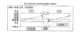
更に、制御手段12は、前記ソーク故障判定に用いる判定値を定めるための所定のマップを3種類設け、この3種類のマップを、図14に示すように、油温差の低い側の故障を判定するための判定値を与える低側マップと、油温差の高い側の故障を判定するための判定値を与える高側マップと、油温差が前記内燃機関3の水温との相関性のある範囲を定めるコアマップとする。 Further, the control means 12 provides three types of predetermined maps for determining the determination values used for the soak failure determination, and these three types of maps are used to determine failures on the side where the oil temperature difference is low as shown in FIG. A low side map that provides a determination value for performing a determination, a high side map that provides a determination value for determining a failure on the side with a high oil temperature difference, and a range in which the oil temperature difference is correlated with the water temperature of the internal combustion engine 3. The core map is determined.
その後、内燃機関始動時における熱害環境判定(内燃機関停止時診断許可)で、条件の成立(hot=1)又は不成立(hot=0)を設定する(ステップA07)。つまり、診断実施するDCの内燃機関停止時の各温度をモニタして、診断実施、及び条件に合った最適な故障判定の判定値を選定する。
この熱害環境判定において、内燃機関始動時の前提条件は、図7に示すように、始動油温(TftSta)が低側油温(TftStaL)と高側油温(TftStaH)の範囲、始動水温(EngWaSta)が低側水温(EngWaStaL)と高側水温(EngWaStaH)の範囲、始動気温(EngArSta)が低側気温(EngArStaL)と高側気温(EngArStaH)の範囲の条件を満たしたときに、成立する。
また、熱害は、図8に示すように、始動気温(EngArSta)が水温に応じて設定された判定値(HotTbl)以上の場合に、判定される。
この熱害環境判定において、内燃機関始動時の各温度を記憶する場合には、図9に示すように、バッテリ電圧が設定電圧(VbSto)以上、エンジン回転数が設定回転数(EngSto)以上、INP回転数が設定回転数(InpSto)以上、車速が設定車速(VholSto)以下、シフトポジションがパーキングレンジ(P)又はニュートラルレンジ(N)、アクセル開度が設定開度(AcclSto)以下の全ての条件が成立したときに、車両停止、かつ内燃機関3の始動とみなして、各温度を記憶する。この温度については、次回の2DC(2回目の運転状態及び時間)において使用するため、2回分以上記憶することができるものである。つまり、始動水温、始動油温、始動気温を、現在のDC格納データ及び前回のDC格納データとして記憶する(図10参照)。
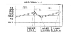
この発明では、各温度の格納タイミングを内燃機関3の停止時、内燃機関次回始動時及び内燃機関次回停止時としている。
詳細は後述するが、先ず、この発明では、内燃機関停止時と内燃機関次回始動時の降温性能による判断と、内燃機関次回始動時と内燃機関次回停止時の昇温性能による判断とを利用して、油温センサ10の故障診断を行う。
また、この発明では、降温性能による判断の後に、昇温性能による判断を行う構成としている。これは、昇温判定による判断を行う場合に、油温センサ10の故障判定の誤判定を防止するためにある程度まで水温が低下していることが、必要であるためである。予め内燃機関3が暖機状態である場合には、水温が比較的高温であって水温の変化量が少ない。この状態で、さらに油温センサ10が高温側でスタック故障している場合、水温及び油温の変化量が共に少なく、且つ同様の変化傾向をとるため、油温センサ10のスタック故障を検出できない場合があるためである。
さらに、この発明では、油温センサ10の故障診断を行う頻度を高めることができる。降温性能による判断を昇温性能による判断よりも先に行うことで、油温センサ10の故障診断を開始するために、予め内燃機関3を冷却して、水温を低下させる時間を設ける必要が無いためである。
また、各温度を記憶する値については、診断開始時間から診断終了時間までの間の各温度の平均値をそれぞれ算出して記憶すること(図11参照)、通信ノイズ等を考慮して一定時間経過したときの温度を記憶すること、各温度はフィルタ後の値を記憶すること、フィルタに関しては定数にて適合可能にすることが、好ましい。
なお、この熱害環境判定は、気温が高い場合に、温度推移が安定しないため、故障判定に水温に応じた熱害判定用の判定値を用い、始動気温が判定値よりも大きい場合に、成立する。
After that, whether the condition is satisfied (hot = 1) or not established (hot = 0) is set (step A07) in the determination of the heat damage environment at the time of starting the internal combustion engine (permitted diagnosis when the internal combustion engine is stopped). In other words, each temperature at the time when the DC internal combustion engine to be diagnosed is stopped is monitored, and a diagnosis determination and an optimal failure determination determination value that meets the conditions are selected.
In this thermal damage environment determination, as shown in FIG. 7, the preconditions at the time of starting the internal combustion engine are that the starting oil temperature (TftSta) is a range between the low side oil temperature (TftSTAL) and the high side oil temperature (TftStah), and the starting water temperature. It is established when (EngWaSta) satisfies the conditions of the low side water temperature (EngWaStaL) and the high side water temperature (EngWaStaH), and the starting air temperature (EngArSta) satisfies the conditions of the low side air temperature (EngArStaL) and the high side air temperature (EngArSTAH). To do.
Further, as shown in FIG. 8, the heat damage is determined when the starting air temperature (EngArSta) is equal to or higher than a determination value (HotTbl) set according to the water temperature.
In this thermal damage environment determination, when each temperature at the start of the internal combustion engine is stored, as shown in FIG. 9, the battery voltage is equal to or higher than the set voltage (VbSto), the engine speed is equal to or higher than the set speed (EngSto), All the cases where the INP speed is equal to or higher than the set speed (InpSto), the vehicle speed is equal to or lower than the set vehicle speed (VholSto), the shift position is equal to the parking range (P) or neutral range (N), and the accelerator opening is equal to or smaller than the set opening (AcclSto). When the condition is satisfied, each temperature is stored assuming that the vehicle is stopped and the internal combustion engine 3 is started. Since this temperature is used in the next 2DC (second operating state and time), it can be stored twice or more. That is, the starting water temperature, the starting oil temperature, and the starting air temperature are stored as the current DC stored data and the previous DC stored data (see FIG. 10).
In the present invention, the storage timing of each temperature is set when the internal combustion engine 3 is stopped, when the internal combustion engine is started next time, and when the internal combustion engine is stopped next time.
As will be described in detail later, first, the present invention uses judgment based on the temperature drop performance when the internal combustion engine is stopped and when the internal combustion engine is next started, and judgment based on the temperature rise performance when the internal combustion engine is next started and when the internal combustion engine is next stopped. Thus, failure diagnosis of the oil temperature sensor 10 is performed.
In the present invention, the determination based on the temperature rise performance is performed after the judgment based on the temperature fall performance. This is because it is necessary that the water temperature is lowered to some extent in order to prevent erroneous determination of the failure determination of the oil temperature sensor 10 when the determination based on the temperature increase determination is performed. When the internal combustion engine 3 is in a warm-up state in advance, the water temperature is relatively high and the amount of change in the water temperature is small. In this state, when the oil temperature sensor 10 has a stack failure on the high temperature side, the amount of change in both the water temperature and the oil temperature is small, and the same change tendency is observed, so that a stack failure in the oil temperature sensor 10 cannot be detected. This is because there are cases.
Furthermore, in the present invention, the frequency of performing failure diagnosis of the oil temperature sensor 10 can be increased. By making the judgment based on the temperature lowering performance prior to the judgment based on the temperature raising performance, it is not necessary to provide time for cooling the internal combustion engine 3 in advance and lowering the water temperature in order to start the failure diagnosis of the oil temperature sensor 10. Because.
As for the value for storing each temperature, the average value of each temperature from the diagnosis start time to the diagnosis end time is calculated and stored (see FIG. 11), and it is determined for a certain time in consideration of communication noise and the like. It is preferable to store the temperature when it has passed, store the value after each filter for each temperature, and make it adaptable with a constant for the filter.
In addition, since the temperature transition is not stable when the air temperature is high, this heat damage environment determination uses a determination value for heat damage determination according to the water temperature for failure determination, and when the starting air temperature is larger than the determination value, To establish.
以上、この発明の実施例について説明してきたが、上述の実施例の構成を請求項毎に当てはめて説明する。
先ず、請求項1に記載の発明において、制御手段12は、内燃機関3の運転停止時に油温センサ10の検出した油温を停止油温として記憶するとともに水温センサ10の検出した水温を停止水温として記憶し、内燃機関3の始動時に油温センサ10の検出した油温を始動油温として記憶するとともに水温センサ5の検出した水温を始動水温として記憶し、記憶された前記停止油温と前記始動油温との差分を算出するとともに、この差分を前記記憶したいずれかの水温に基づいて所定の条件で定めた判定値と比較することによって油温センサ10の故障判定を行う。
これにより、診断実施可否判断の実施時期を限定する走行条件を重要としないようにでき、走行条件を必要とせずに、故障診断の判断を実施することができる。また、水温の状態に応じて判定値(閾値)が変更可能であり、判定精度を高めることができる。更に、基本的に検出した油温、水温だけで判断するので、制御が簡単で制御手段12の演算負荷が小さく、個々の車両への適合も容易にできる。
請求項2に記載の発明において、制御手段12は、油温センサ10の故障判定として、前回停止時の停止油温と今回始動時の始動油温との第一油温差を算出し、前記記憶したいずれかの水温に基づいて所定の条件で定めた判定値と前記第一油温差とを比較して行う油温センサ10のソーク故障判定と、次回始動時の始動油温と次回停止時の停止油温との第二油温差を算出し、前記記憶したいずれかの水温に基づいて所定の条件で定めた判定値と前記第二油温差とを比較して行う油温センサ10の昇温故障判定との一つ以上の判定を行う。
これにより、内燃機関停止時での降温性能と運転中の昇温性能とのいずれかのみによる判断であっても、より多くの温度範囲(内燃機関3を運転する常温域として、従来は不可能であった20℃〜140℃の範囲の全域を含む)で故障診断が可能となる。
請求項3に記載の発明において、制御手段12は、前記ソーク故障判定と前記昇温故障判定との2つの判定を行い、前記ソーク故障判定では、前回停止時の停止油温と今回始動時の始動油温との第一油温差を算出し、前記停止水温に基づいて所定のマップで定めた判定値と前記第一油温差とを比較して行い、前記昇温故障判定では、次回始動時の始動油温と次回停止時の停止油温との第二油温差を算出し、前記始動水温に基づいて所定のマップで定めた判定値と前記第二油温差とを比較して行う。
これにより、内燃機関停止時での降温性能と運転中の昇温性能との両方による判断であるため、精度が高く、また、より多くの温度範囲で故障診断が可能となる。
請求項4に記載の発明において、制御手段12は、内燃機関3の置かれた環境の温度を検出可能とする気温センサとしての吸気温センサ13に連絡し、前記判定値を定めるために3つの判定を行い、この3つの判定を、前記油温と前記水温の乖離度を考慮する乖離判定と、計時手段12Bによって計測された内燃機関3のソーク時間を考慮するソーク判定と、吸気温センサ13によって検出された気温を考慮する熱害判定とし、前記ソーク故障判定と前記昇温故障判定との2つの故障判定に用いる判定値を8パターン設定し、前記乖離判定と前記ソーク判定と前記熱害判定との3つの判定結果に基づいてこのうち一つのパターンを選択する。
これにより、車両1の置かれた環境と車両の運転状態を考慮した8パターンにより、きめ細かく判定値を設定できるので、精度を極めて高くでき、誤判定を少なくできる。また、内燃機関3の水温との相関性を考慮し、車両の置かれた環境と車両の運転状態とを考慮した3つの判断によって8パターンに振り分けるので、個々の判定値の設定を最適にでき、グレーゾーンを小さくできる。
請求項5に記載の発明において、制御手段12は、前記乖離判定を、前記停止油温と前記停止水温との差分を水温に基づく判定値によって判定する2値判定とし、前記ソーク判定を、予め固有値として設定したソーク判定時間によって判定する2値判定とし、前記熱害判定を、吸気温センサ13が内燃機関3の始動時に計測した気温を水温に基づく判定値によって判定する2値判定とする。
これにより、車両1の置かれた環境と車両の運転状態を考慮した8パターンについての選択(パターン決定)を簡素化でき、制御手段12の演算負荷を小さくできる。
請求項6に記載の発明において、制御手段12は、前記ソーク故障判定に用いる判定値を定めるための所定のマップを3種類設け、この3種類のマップを、油温差の低い側の故障を判定するための判定値を与える低側マップと、油温差の高い側の故障を判定するための判定値を与える高側マップと、油温差が内燃機関3の水温との相関性のある範囲を定めるコアマップとする。
これにより、ソーク判定の概要図に示すように、広い温度範囲にわたって、また、各温度において最適な判定値を与えることができ、精度の高い故障診断が可能となる。
Although the embodiments of the present invention have been described above, the configuration of the above-described embodiments will be described for each claim.
First, in the first aspect of the invention, the control means 12 stores the oil temperature detected by the oil temperature sensor 10 when the operation of the internal combustion engine 3 is stopped as the stop oil temperature, and the water temperature detected by the water temperature sensor 10 is the stop water temperature. And the oil temperature detected by the oil temperature sensor 10 at the start of the internal combustion engine 3 is stored as the start oil temperature, the water temperature detected by the water temperature sensor 5 is stored as the start water temperature, and the stored stop oil temperature and the While calculating the difference from the starting oil temperature, the failure determination of the oil temperature sensor 10 is performed by comparing this difference with a determination value determined under a predetermined condition based on any one of the stored water temperatures.
As a result, the driving conditions that limit the execution timing of the diagnosis feasibility determination can be made unimportant, and the determination of the failure diagnosis can be performed without requiring the driving conditions. Further, the determination value (threshold value) can be changed according to the state of the water temperature, and the determination accuracy can be improved. Furthermore, since the judgment is basically made only by the detected oil temperature and water temperature, the control is simple, the calculation load of the control means 12 is small, and adaptation to individual vehicles can be easily performed.
In the invention according to claim 2, the control means 12 calculates the first oil temperature difference between the stop oil temperature at the previous stop and the start oil temperature at the current start as the failure determination of the oil temperature sensor 10, and stores the memory and soak failure determination of the oil temperature sensor 10 performed by comparing the judgment value and the first oil temperature difference that defines a predetermined condition based on any of the water temperature, and the starting oil temperature and the next time stopped at the next time start Of the oil temperature sensor 10 which calculates a second oil temperature difference from the stop oil temperature at the time and compares the second oil temperature difference with a determination value determined under a predetermined condition based on any one of the stored water temperatures One or more judgments with temperature rising fault judgment are performed.
As a result, even if the judgment is based only on the temperature lowering performance when the internal combustion engine is stopped or the temperature raising performance during operation, it is impossible in the past as a larger temperature range (normal temperature range where the internal combustion engine 3 is operated). (Including the entire range of 20 ° C. to 140 ° C.).
In the invention according to claim 3, the control means 12 performs two determinations, the soak failure determination and the temperature rising failure determination. In the soak failure determination, the stop oil temperature at the previous stop and the current start time are determined. calculating a first oil temperature difference starting oil temperature Prefecture, on the basis of the stop temperature is performed by comparing the first oil temperature difference and the determination value determined by the predetermined map, in the Atsushi Nobori failure determination, starting next time calculating a second oil temperature difference starting oil temperature and the next time stop time of stopping the oil temperature Prefecture when performed by comparing the second oil temperature difference and the determination value determined by a predetermined map based on the starting water temperature .
Thereby, since the determination is based on both the temperature lowering performance when the internal combustion engine is stopped and the temperature increasing performance during operation, the accuracy is high, and the failure diagnosis can be performed in a larger temperature range.
In the invention according to claim 4, the control means 12 communicates with an intake air temperature sensor 13 as an air temperature sensor capable of detecting the temperature of the environment where the internal combustion engine 3 is placed, and determines three determination values to determine the determination value. The three determinations are made as follows: a divergence determination that considers the degree of divergence between the oil temperature and the water temperature; a soak determination that considers the soak time of the internal combustion engine 3 measured by the time measuring means 12B; and an intake air temperature sensor 13 The heat damage determination taking into account the temperature detected by the above, and eight patterns of determination values used for two failure determinations of the soak failure determination and the temperature rising failure determination are set, and the deviation determination, the soak determination and the heat damage are set One pattern is selected based on the three determination results.
Thereby, since the determination value can be set finely by 8 patterns in consideration of the environment in which the vehicle 1 is placed and the driving state of the vehicle, the accuracy can be extremely increased and erroneous determination can be reduced. In addition, considering the correlation with the water temperature of the internal combustion engine 3, it is divided into 8 patterns by three judgments that take into account the environment in which the vehicle is placed and the driving state of the vehicle, so that the setting of each judgment value can be optimized. The gray zone can be reduced.
In the invention according to claim 5, the control unit 12 sets the deviation determination as a binary determination in which a difference between the stop oil temperature and the stop water temperature is determined based on a determination value based on a water temperature, and the soak determination is performed in advance. The binary determination is determined by the soak determination time set as the eigenvalue, and the thermal damage determination is a binary determination in which the air temperature measured by the intake air temperature sensor 13 at the start of the internal combustion engine 3 is determined by a determination value based on the water temperature.
Thereby, the selection (pattern determination) about 8 patterns in consideration of the environment where the vehicle 1 is placed and the driving state of the vehicle can be simplified, and the calculation load of the control means 12 can be reduced.
In the invention according to claim 6, the control means 12 provides three types of predetermined maps for determining determination values used for the soak failure determination, and these three types of maps are used to determine failures on the low oil temperature difference side. A low-side map that provides a determination value for performing a determination, a high-side map that provides a determination value for determining a failure on the higher oil temperature difference, and a range in which the oil temperature difference is correlated with the water temperature of the internal combustion engine 3 A core map is used.
As a result, as shown in the schematic diagram of soak determination, an optimal determination value can be given over a wide temperature range and at each temperature, and highly accurate failure diagnosis is possible.
なお、この発明においては、油温センサ以外の昇降性のある温度センサ(エンジン水温センサ、吸気温センサ等)については、同様の診断が可能である。
また、油温センサについても、2個搭載したものについては、油温センサ同士で診断を可能とする。
更に、気温を使用することにより、熱害等の温度降下が安定しないパターンについても、判定値を分けることにより、より精度の高い診断が可能となる。
In the present invention, the same diagnosis is possible for temperature sensors (such as an engine water temperature sensor and an intake air temperature sensor ) having a lift function other than the oil temperature sensor.
In addition, regarding two oil temperature sensors, two oil temperature sensors can be diagnosed with each other.
Furthermore, by using the temperature, even with respect to a pattern in which the temperature drop such as heat damage is not stable, it is possible to make a more accurate diagnosis by dividing the determination value.
Claims (6)
Priority Applications (1)
| Application Number | Priority Date | Filing Date | Title |
|---|---|---|---|
| JP2011054132A JP5679118B2 (en) | 2011-03-11 | 2011-03-11 | Oil temperature sensor fault diagnosis control device |
Applications Claiming Priority (1)
| Application Number | Priority Date | Filing Date | Title |
|---|---|---|---|
| JP2011054132A JP5679118B2 (en) | 2011-03-11 | 2011-03-11 | Oil temperature sensor fault diagnosis control device |
Publications (3)
| Publication Number | Publication Date |
|---|---|
| JP2012189162A JP2012189162A (en) | 2012-10-04 |
| JP2012189162A5 true JP2012189162A5 (en) | 2013-12-05 |
| JP5679118B2 JP5679118B2 (en) | 2015-03-04 |
Family
ID=47082562
Family Applications (1)
| Application Number | Title | Priority Date | Filing Date |
|---|---|---|---|
| JP2011054132A Active JP5679118B2 (en) | 2011-03-11 | 2011-03-11 | Oil temperature sensor fault diagnosis control device |
Country Status (1)
| Country | Link |
|---|---|
| JP (1) | JP5679118B2 (en) |
Families Citing this family (1)
| Publication number | Priority date | Publication date | Assignee | Title |
|---|---|---|---|---|
| JP5411998B1 (en) * | 2012-12-28 | 2014-02-12 | 富士重工業株式会社 | Temperature sensor diagnostic device |
Family Cites Families (5)
| Publication number | Priority date | Publication date | Assignee | Title |
|---|---|---|---|---|
| JPH09329222A (en) * | 1996-06-11 | 1997-12-22 | Mazda Motor Corp | Failure judging device of oil temperature detecting means in automatic transmission |
| KR100570325B1 (en) * | 2004-01-07 | 2006-04-11 | 주식회사 케피코 | rationality check method of oil temperature sensor |
| JP2006177412A (en) * | 2004-12-21 | 2006-07-06 | Toyota Motor Corp | Oil temperature sensor breakdown detection device of automatic transmission |
| JP2006276004A (en) * | 2005-03-01 | 2006-10-12 | Fujitsu Ten Ltd | Method and device for deciding abnormality of temperature detection means |
| JP5195475B2 (en) * | 2009-02-04 | 2013-05-08 | トヨタ自動車株式会社 | Oil temperature sensor abnormality determination device and abnormality determination method |
-
2011
- 2011-03-11 JP JP2011054132A patent/JP5679118B2/en active Active
Similar Documents
| Publication | Publication Date | Title |
|---|---|---|
| CN105599700B (en) | Method and system for temperature sensor fault detection | |
| US11454161B2 (en) | Thermostat fault diagnosis method and device, computer device and storage medium | |
| US7921705B2 (en) | Engine coolant temperature estimation system | |
| JP4561529B2 (en) | Failure detection system for internal combustion engine cooling system | |
| JP5375790B2 (en) | Abnormality determination apparatus and abnormality determination method | |
| US10101377B2 (en) | Thermal monitoring of a converter | |
| US20120033705A1 (en) | Method and device for diagnosing a thermostat | |
| US8788165B2 (en) | Abnormal state diagnosis method for oil temperature sensor of automatic transmission | |
| JP2016176431A (en) | Diagnostic device for temperature sensor | |
| JP2007040109A5 (en) | ||
| JP6351614B2 (en) | How to manage the powertrain by performing an engine temperature estimate at the end of the downtime of the powertrain elements | |
| US9046172B2 (en) | Automatic transmission control apparatus | |
| KR20100101684A (en) | Method for checking the plausibility of a temperature value in an internal combustion engine | |
| JP3851203B2 (en) | Shift control device and shift control method for automatic transmission | |
| JP6051659B2 (en) | Oil temperature sensor fault diagnosis control device | |
| US7857508B2 (en) | Method for monitoring the functionality of a temperature sensor | |
| JP2012189162A5 (en) | ||
| SE536553C2 (en) | Diagnosis of boot system | |
| JP5679118B2 (en) | Oil temperature sensor fault diagnosis control device | |
| JP5258902B2 (en) | Engine management system method and engine management system | |
| JP5411998B1 (en) | Temperature sensor diagnostic device | |
| JP2013019484A (en) | Failure diagnosis device for oil temperature sensor | |
| JP2009228773A (en) | Control device of automatic transmission | |
| JP2012052633A (en) | Failure determining device of oil temperature sensor | |
| KR101013665B1 (en) | Apparatus and method for driving engine of car |