JP5679118B2 - Oil temperature sensor fault diagnosis control device - Google Patents
Oil temperature sensor fault diagnosis control device Download PDFInfo
- Publication number
- JP5679118B2 JP5679118B2 JP2011054132A JP2011054132A JP5679118B2 JP 5679118 B2 JP5679118 B2 JP 5679118B2 JP 2011054132 A JP2011054132 A JP 2011054132A JP 2011054132 A JP2011054132 A JP 2011054132A JP 5679118 B2 JP5679118 B2 JP 5679118B2
- Authority
- JP
- Japan
- Prior art keywords
- oil temperature
- temperature
- temperature sensor
- oil
- failure
- Prior art date
- Legal status (The legal status is an assumption and is not a legal conclusion. Google has not performed a legal analysis and makes no representation as to the accuracy of the status listed.)
- Active
Links
Images


Description
この発明は、油温センサの故障診断制御装置に係り、特に車両のパワートレーンに用いられる変速機等の動力伝達機構に使用される作動油の温度を検出する油温センサの故障を診断する油温センサの故障診断制御装置に関する。
BACKGROUND OF THE
車両においては、パワートレーンに用いられる変速機等の動力伝達機構に使用される作動油の温度を検出するための油温センサを備えるとともに、この油温センサの故障診断をするための故障診断制御装置を備えている。
このような油温センサの故障診断制御装置においては、油温20℃以下のスタック(出力信号がある値に固着している状態)を検出し、所定のアクセル開度条件等で走行条件を満たしたときに、所定時間にわたり油温が変化していない場合に、スタック故障と判定している。
The vehicle includes an oil temperature sensor for detecting the temperature of hydraulic oil used in a power transmission mechanism such as a transmission used in the power train, and a failure diagnosis control for diagnosing the failure of the oil temperature sensor. Equipment.
In such an oil temperature sensor failure diagnosis control device, a stack having an oil temperature of 20 ° C. or less (state in which the output signal is fixed to a certain value) is detected, and the driving condition is satisfied by a predetermined accelerator opening condition or the like. When the oil temperature has not changed over a predetermined time, it is determined that the stack has failed.
特許文献1に係る車両用温度センサの異常判定装置は、車両の駆動系部位の温度が所定の温度領域に連続して含まれる経過時間を計測し、この計測された経過時間が所定温度に達した場合に温度センサの異常と判定するものである。
特許文献2に係る自動変速機の故障診断装置は、シフト位置が走行レンジ位置以外で、かつ、油温信号の電圧値が設定値以下であると判断されたときに、タイマが設定時間に達した場合に、油温センサの故障とその警告を行うものである。
特許文献3に係る自動変速機の油温センサ欠陥検出方法は、自動変速機の油温を検出して油温センサの欠陥による他の故障を正確に判断し、車両の各運転モードにおける推定された油温を用いてセンサ故障時の代替油温を計算して変速制御を低減するものである。
特許文献4に係る作動油温度センサの異常判定装置は、内燃機関の水温と変速機の油温との差分が閾値以上の場合に、油温センサが異常であると判定するものである。
特許文献5に係る制御装置及び制御方法は、内燃機関の水温と変速機の油温との差が第1所定値よりも小さい第3閾値以下の場合に、油温センサが仮異常であると判定し、この仮異常が所定回数以上判定した場合に、油温センサが本異常であると判定するものである。
特許文献6に係る自動変速機の油温センサ故障検出装置は、車両の所定の走行時間を、エンジンを始動させたときの油温に応じて可変させ、油温センサの故障を判定するものである。
特許文献7に係る温度センサの故障判定装置は、エンジンが運転された後、停止され、かつ、故障判定条件を満たしているときには、エンジンの停止後一定時間経過後、温度センサの故障を判定するものである。
An abnormality determination device for a temperature sensor for a vehicle according to
In the automatic transmission failure diagnosis apparatus according to
The oil temperature sensor defect detection method for an automatic transmission according to
The hydraulic oil temperature sensor abnormality determination device according to
In the control device and the control method according to
An oil temperature sensor failure detection device for an automatic transmission according to
The temperature sensor failure determination device according to
ところが、従来、油温昇温を利用して油温センサの故障を検出しているため、油温が飽和する領域での故障の検出(例えば、油温20℃以下、140℃以上のみで検出)が困難であった。また、車両の走行時に油温センサの故障を検出するため、走行条件等で検出領域が限定されている。このような理由により、故障の検出性の低下、頻度低下する原因となっていた。
また、油温センサの故障が確定するまでの時間が長くかかる傾向があった。また、診断判定値を決定するにあたり、油温昇温性の確認が必要となり、確認、適合工数が多くかかっていた。更に、車両部品の変更により、クーラ性能が変更になる場合に(バンパ変更、油量変更、クーラ変更等)、確認工数が大となるという不都合があった。
However, since the oil temperature sensor failure is detected conventionally using the oil temperature rise, the failure detection in the region where the oil temperature is saturated (for example, detection only when the oil temperature is 20 ° C. or lower, 140 ° C. or higher) ) Was difficult. Further, since a failure of the oil temperature sensor is detected when the vehicle is traveling, the detection area is limited by traveling conditions and the like. For these reasons, it has become a cause of failure detection failure and frequency reduction.
Moreover, there is a tendency that it takes a long time until the failure of the oil temperature sensor is determined. In addition, when determining the diagnostic judgment value, it is necessary to confirm the oil temperature temperature rise performance, which requires a lot of confirmation and conformity man-hours. Furthermore, when the cooler performance is changed due to a change in vehicle parts (bumper change, oil amount change, cooler change, etc.), there is a disadvantage that the number of confirmation steps becomes large.
そこで、この発明の目的は、より広い検出領域での故障診断を可能にすること、故障診断を行う頻度を高めること、故障を確定するまでの所要時間を短縮すること、検出精度を高めること、その故障診断にかかる制御手段への演算負荷を小さく抑制し、特に、検出領域を、油温が飽和する領域まで広げ、走行条件によって極めて限定された領域をより広げて診断を可能とする油温センサの故障診断制御装置を提供することにある。 Therefore, the object of the present invention is to enable failure diagnosis in a wider detection area, increase the frequency of performing failure diagnosis, shorten the time required to determine a failure, improve detection accuracy, The oil temperature that reduces the computational load on the control means involved in the failure diagnosis, and in particular, extends the detection area to the area where the oil temperature saturates, and further expands the area that is extremely limited by the running conditions. An object of the present invention is to provide a sensor fault diagnosis control device.
この発明は、内燃機関を搭載する車両の動力伝達機構に使用される作動油の温度を検出する油温センサを設け、前記内燃機関の冷却水の水温を検出する水温センサを設け、前記油温センサの故障の有無を判定する故障判定手段を備えた油温センサの故障診断制御装置において、前記内燃機関の運転停止時に前記油温センサの検出した油温を停止油温として記憶するとともに前記水温センサの検出した水温を停止水温として記憶し、前記内燃機関の始動時に前記油温センサの検出した油温を始動油温として記憶するとともに前記水温センサの検出した水温を始動水温として記憶する記憶手段を備え、前記故障判定手段は、記憶された前記停止油温と前記始動油温との油温差分を算出するとともに記憶された前記停止水温と前記始動水温との水温差分を算出し、前記油温差分と前記水温差分との相関性に基づいて前記油温センサの故障判定を行うことを特徴とする。 The present invention, an oil temperature sensor for detecting a temperature of the hydraulic oil used in a power transmission mechanism of a vehicle equipped with the internal combustion engine is provided, is provided a water temperature sensor for detecting the temperature of the coolant of the internal combustion engine, the oil temperature In an oil temperature sensor failure diagnosis control apparatus comprising failure determination means for determining whether or not a sensor has failed, the oil temperature detected by the oil temperature sensor when the operation of the internal combustion engine is stopped is stored as a stop oil temperature and the water temperature Storage means for storing the water temperature detected by the sensor as a stop water temperature, storing the oil temperature detected by the oil temperature sensor as the starting oil temperature at the start of the internal combustion engine, and storing the water temperature detected by the water temperature sensor as the starting water temperature The failure determination means calculates an oil temperature difference between the stored stop oil temperature and the start oil temperature, and stores the water temperature between the stop water temperature and the start water temperature stored. Min is calculated and is characterized in that the failure determination of the oil temperature sensor based on a correlation between the temperature difference and the oil temperature difference.
この発明の油温センサの故障診断制御装置は、より広い検出領域での故障診断を可能とし、故障診断を行う頻度を高め、故障を確定するまでの所要時間を短縮し、検出精度を高め、その故障診断にかかる制御手段への演算負荷を小さく抑制し、特に、検出領域を油温が飽和する領域まで広げ、走行条件によって極めて限定された領域をより広げて診断を可能とする。 The failure diagnosis control device for the oil temperature sensor of the present invention enables failure diagnosis in a wider detection area, increases the frequency of performing failure diagnosis, shortens the time required to determine the failure, and increases detection accuracy, The calculation load on the control means related to the failure diagnosis is suppressed to a small level. In particular, the detection region is expanded to a region where the oil temperature is saturated, and the region that is extremely limited by the running conditions is further expanded to enable diagnosis.
この発明は、より広い検出領域での故障診断を可能にすること、故障診断を行う頻度を高めること、故障を確定するまでの所要時間を短縮すること、検出精度を高めること、その診断にかかる制御手段への演算負荷を小さく抑制し、特に、検出領域を、油温が飽和する領域まで広げ、走行条件によって極めて限定された領域をより広げて診断を可能とする目的を、記憶された停止油温と始動油温との差分を記憶したいずれかの水温に基づいて所定の条件で定めた判定値と比較することによって油温センサの故障判定を行うことにより実現するものである。 The present invention enables failure diagnosis in a wider detection area, increases the frequency of failure diagnosis, shortens the time required to determine a failure, increases detection accuracy, and relates to the diagnosis Stored stop for the purpose of minimizing the computational load on the control means and, in particular, expanding the detection area to the area where the oil temperature saturates and enabling the diagnosis by further expanding the area that is extremely limited by the driving conditions This is realized by determining the failure of the oil temperature sensor by comparing the difference between the oil temperature and the starting oil temperature with a determination value determined under a predetermined condition based on one of the stored water temperatures.
図1〜図21は、この発明の実施例を示すものである。
図3において、1は車両、2はこの車両1に搭載されるパワートレインである。
このパワートレイン2は、内燃機関3と、この内燃機関3に連結した動力伝達機構としての変速機(自動変速機)4とからなる。
内燃機関3には、冷却水の温度としての水温を検出する水温センサ5が設けられている。
変速機4には、各バルブを作動する複数のソレノイドとしての第1〜第4ソレノイド6〜9と、この第1〜第4ソレノイド6〜9の作動油の温度を検出する油温センサ10とが設けられている。
1 to 21 show an embodiment of the present invention.
In FIG. 3, 1 is a vehicle, and 2 is a power train mounted on the
The
The
The
車両1は、図2に示すように、油温センサ10の故障診断制御装置11を備える。
この故障診断制御装置11は、内燃機関停止時の水温、油温、気温を記憶し、次回の内燃機関始動時に各温度の相関を診て、油温センサ10の故障診断を行うものであって、車両1の走行中、内燃機関停止時、内燃機関始動時に状況を判定することで、診断禁止、及び各状況に合った判定値(閾値)を用いて対応するものである。
この故障診断制御装置11には、制御手段(TUC)12が設けられている。
この制御手段12には、水温センサ5と、第1〜第4ソレノイド6〜9と、油温センサ10とが連絡している。
また、この制御手段12には、内燃機関3への吸気温を内燃機関3の置かれた環境の温度(以下「気温」と称する)として検出可能な気温センサである吸気温センサ13と、アクセルペダルの踏み込み量をアクセル開度として検出するアクセル開度センサ14と、車速を検出する車速センサ15と、エンジン回転数を検出するエンジン回転数センサ16と、バッテリ電圧を検出可能なバッテリ電圧検出センサ17と、イグニションスイッチ18と、シフトポジションの検出が可能なシフトポジションスイッチ19と、内燃機関3の始動時・停止時を検出可能な内燃機関始動停止検出センサ20とが連絡している。
As shown in FIG. 2, the
This failure
The failure
A
The control means 12 includes an intake
制御手段12は、図2に示すように、油温センサ10の検出した油温に基づいて油温センサ10の異常状態を判定する故障判定手段12Aと、経過時間を計測する計時手段12Bと、少なくとも検出された油温及び水温を記憶する記憶手段12Cとを備えている。
そして、制御手段12は、内燃機関3の運転停止時に油温センサ10の検出した油温を停止油温として記憶するとともに水温センサ5の検出した水温を停止水温として記憶し、内燃機関3の始動時に油温センサ10の検出した油温を始動油温として記憶するとともに水温センサ5の検出した水温を始動水温として記憶し、記憶された前記停止油温と前記始動油温との差分を算出するとともに、この差分を前記記憶したいずれかの水温に基づいて所定の条件で定めた判定値と比較することによって油温センサ10の故障判定を行う。
なお、現在温度の検出値となる水温、油温、気温については、直ぐに演算を用いるため、一時的な記憶(揮発性)でも実施可能であるので、不揮発性メモリに記憶させないようにすることも可能である。
As shown in FIG. 2, the
Then, the control means 12 stores the oil temperature detected by the
Note that the water temperature, oil temperature, and air temperature, which are the detected values of the current temperature, are immediately calculated, and can be stored even temporarily (volatile), so that they may not be stored in the nonvolatile memory. Is possible.
また、制御手段12は、油温センサ10の故障判定として、前回停止時の停止油温と今回始動時の始動油温との第一油温差を算出し、前記記憶したいずれかの水温に基づいて所定の条件で定めた判定値と前記第一油温差とを比較して行う油温センサ10のソーク故障判定(図14参照)と、次回始動時の始動油温と次回停止時の停止油温との第二油温差を算出し、前記記憶したいずれかの水温に基づいて所定の条件で定めた判定値と前記第二油温差とを比較して行う前記油温センサ10の昇温故障判定(図15参照)との一つ以上の判定を行う。
Further, as a failure determination of the
更に、制御手段12は、前記ソーク故障判定と前記昇温故障判定との2つの判定を行い、前記ソーク故障判定では、前回停止時の停止油温と今回始動時の始動油温との第一油温差を算出し、前記停止水温に基づいて所定のマップで定めた判定値と前記第一油温差とを比較して行い、前記昇温故障判定では、次回始動時の始動油温と次回停止時の停止油温との第二油温差を算出し、前記始動水温に基づいて所定のマップで定めた判定値と前記第二油温差とを比較して行う。 Furthermore, the control means 12 performs two determinations, the soak failure determination and the temperature rising failure determination. In the soak failure determination, the first of the stop oil temperature at the previous stop and the start oil temperature at the current start is determined. calculating the oil temperature difference, the performed based on the stop temperature is compared with the first oil temperature difference and the determination value determined by the predetermined map, said at a heating failure determination is the start oil temperature at the time of the next time start the next A second oil temperature difference from the stop oil temperature at the time of stopping the rotation is calculated, and a determination value determined by a predetermined map based on the start water temperature is compared with the second oil temperature difference.
更にまた、制御手段12は、内燃機関3の置かれた環境の温度を検出可能とする気温センサとしての吸気温センサ13に連絡し、前記判定値を定めるために3つの判定を行い、この3つの判定を、前記油温と前記水温の乖離度を考慮する乖離判定と、前記計時手段12Bによって計測された前記内燃機関3のソーク時間を考慮するソーク判定と、前記気温センサ13によって検出された気温を考慮する熱害判定とし、前記前記ソーク故障判定と前記昇温故障判定との2つの故障判定に用いる判定値を8パターン設定し(図12参照)、前記乖離判定と前記ソーク判定と前記熱害判定との3つの判定結果に基づいてこのうち一つのパターンを選択する。
なお、気温センサとしては、吸気温センサ13を例示したが、エンジンルームや内燃機関3の雰囲気温度を検出する外気温センサ等のセンサでも可能である。
Furthermore, the control means 12 communicates with an intake
In addition, although the intake
また、制御手段12は、前記乖離判定を、前記停止油温と前記停止水温との差分を水温に基づく判定値によって判定する2値判定とし、前記ソーク判定を、予め固有値として設定したソーク判定時間によって判定する2値判定とし、前記熱害判定を、前記気温センサとしての吸気温センサ13が前記内燃機関3の始動時に計測した気温を水温に基づく判定値によって判定する2値判定とする。
Moreover, the control means 12 makes the said divergence determination the binary determination which determines the difference of the said stop oil temperature and the said stop water temperature by the determination value based on water temperature, The soak determination time which set the said soak determination as an eigenvalue previously The thermal damage determination is a binary determination in which the air temperature measured by the intake
更に、制御手段12は、前記ソーク故障判定に用いる判定値を定めるための所定のマップを3種類設け、この3種類のマップを、図14に示すように、油温差の低い側の故障を判定するための判定値を与える低側マップと、油温差の高い側の故障を判定するための判定値を与える高側マップと、油温差が前記内燃機関3の水温との相関性のある範囲を定めるコアマップとする。
Further, the control means 12 provides three types of predetermined maps for determining the determination values used for the soak failure determination, and these three types of maps are used to determine failures on the side where the oil temperature difference is low as shown in FIG. A low side map that provides a determination value for performing a determination, a high side map that provides a determination value for determining a failure on the side with a high oil temperature difference, and a range in which the oil temperature difference is correlated with the water temperature of the
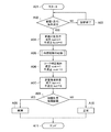
次に、この実施例に係る油温センサ10の故障診断を、図1にフローチャートに基づいて説明する。
図1に示すように、制御手段12のプログラムがスタートすると(ステップA01)、先ず、油温センサ10の故障診断の前提(走行)条件が成立したか否かを判断する(ステップA02)。つまり、診断実施する直前のDC(ドライビングサイクル)走行をモニタして、故障診断を実施するかどうかを判断する。
この故障診断を実施は、走行条件が成立し、かつ、登坂(ストール)条件が不成立である場合に行われる。
走行条件は、油温が設定範囲、水温が設定範囲、気温が設定範囲、内燃機関3のオン時間が設定時間以上、内燃機関3のアイドル運転時間が設定時間以上、アクセル開度積算時間が設定時間以上、車速が設定車速以上、走行時間が設定時間以上の全ての条件が満たされた場合に、成立する。
登坂(ストール)条件は、ストール判定の成立時で、かつ、ストール解除タイマが零(0)以上である場合に、成立する。
ストール判定は、アクセル開度が設定開度以上、変速機4においてロックアップ・スリップのいずれの状態でもないとき、シフトポジションがパーキングレンジ(P)・ニュートラルレンジ(N)以外のときの全ての条件が満たされた場合に、成立する。アクセル開度の設定開度は、車速に応じて定められるものである。
ストール解除タイマの動作例においては、図4に示すように、ストール判定が成立し(診断条件が停止)、そして、このストール判定の成立から不成立になった時に(「ストール確定」として記す)、ストール解除タイマでストール減衰時間(sec)をセットして、このストール減衰時間を減衰し、このストール減衰時間が零(0)になった時に、診断条件を復帰させる。
Next, failure diagnosis of the
As shown in FIG. 1, when the program of the control means 12 is started (step A01), it is first determined whether or not a precondition (running) condition for failure diagnosis of the
This failure diagnosis is performed when the traveling condition is satisfied and the uphill (stall) condition is not satisfied.
The running conditions are: oil temperature is set range, water temperature is set range, air temperature is set range,
The uphill (stall) condition is satisfied when the stall determination is satisfied and the stall release timer is equal to or greater than zero (0).
Stall judgment is all conditions when the accelerator opening is equal to or greater than the set opening, the
In the operation example of the stall release timer, as shown in FIG. 4, when the stall determination is satisfied (diagnostic condition is stopped), and when the stall determination is not satisfied (denoted as “stall confirmation”), The stall decay time (sec) is set by the stall release timer, the stall decay time is attenuated, and when the stall decay time becomes zero (0), the diagnosis condition is restored.
前記ステップA02がNOの場合には、故障診断を終了して(ステップA03)、前記ステップA02に戻す。 If step A02 is NO, the fault diagnosis is terminated (step A03), and the process returns to step A02.
前記ステップA02がYESの場合には、内燃機関3の停止時における乖離(Kairi)判定で、条件の成立(Kairi=1)又は不成立(Kairi=0)を設定する(ステップA04)。つまり、診断実施する直前のDCの内燃機関停止時に各温度をモニタして、診断実施及び条件に合った最適な故障の判定値を選定する。
この乖離判定では、エンジン回転数が設定回転数以下とイグニションスイッチ18がオフとの条件のいずれかが成立し、かつ、バッテリ電圧が設定電圧以上、INP(入力)回転数が設定回転数以下、車速が設定車速以下、シフトポジションがパーキングレンジ(P)又はニュートラルレンジ(N)、アクセル開度が設定開度以下の全ての条件が成立した場合に、車両停止かつ内燃機関停止とみなし、停止水温、停止油温、停止気温の各温度のフィルタ後の値を記憶する。なお、このフィルタに関しては、定数にて適合が可能である。
また、内燃機関停止時の前提条件は、停止水温が設定範囲、停止油温が設定範囲、停止気温が設定範囲の全ての条件を満たしたときに、成立する。
そして、乖離判定においては、記憶した水温、記憶した油温により実施し、乖離度が大きい場合には、故障判定に水温に応じて設定される専用の判定値を用いる。
乖離状態は、図5に示すように、停止水温(EngWaFin)が停止油温(TftFin)以上のときには、停止水温(EngWaFin)から停止油温(TftFin)を減算した値が第一の判定値(KaiTb1)以上の条件、又は、停止油温(TftFin)が停止水温(EngWaFin)よりも大きい場合には、停止油温(TftFin)から停止水温(EngWaFin)を減算した値が第二の判定値(KaiTb2)以上の条件が成立したときに、判定される。ここで、上記の第一の判定値(KaiTb1)及び第二の判定値(KaiTb2)は、水温に応じて定められるものである。
When step A02 is YES, whether the condition is satisfied (Kairi = 1) or not satisfied (Kairi = 0) is set in the deviation (Kairi) determination when the
In this deviation determination, one of the conditions that the engine speed is equal to or lower than the set speed and the
Moreover, the preconditions when the internal combustion engine is stopped are satisfied when the stop water temperature satisfies all the conditions of the set range, the stop oil temperature of the set range, and the stop air temperature of the set range.
The deviation determination is performed based on the stored water temperature and the stored oil temperature. When the deviation degree is large, a dedicated determination value set according to the water temperature is used for the failure determination.
As shown in FIG. 5, when the stop water temperature (EngWaFin) is equal to or higher than the stop oil temperature (TftFin), the difference state is obtained by subtracting the stop oil temperature (TftFin) from the stop water temperature (EngWaFin). KaiTb1) or more conditions, or when the stop oil temperature (TftFin) is larger than the stop water temperature (EngWaFin), the value obtained by subtracting the stop water temperature (EngWaFin) from the stop oil temperature (TftFin) is the second judgment value ( It is determined when the above condition is satisfied. Here, the first determination value (KaiTb1) and the second determination value (KaiTb2) are determined according to the water temperature.
前記ステップA04の処理後は、内燃機関3を始動する(ステップA05)。
After the process of step A04, the
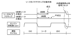
そして、この内燃機関3の始動後は、ソーク判定で、条件の成立(soak=1)又は不成立(soak=0)を設定する(ステップA06)。つまり、ソーク判定(例えば、5時間判定)を利用して、温度が安定した領域にて診断を実施することにより、精度を向上させる制御を実施する。
例えば、図6に示すように、車両のソーク判定を実施し(「ソーク」として記す)、ソーク判定時間内に十分なソークが行われている場合は、診断精度の向上のために、別に判定値を用いて診断を行い、成立(soak=1)か不成立(soak=0)かを設定する。
After the
For example, as shown in FIG. 6, when vehicle soak determination is performed (denoted as “soak”) and sufficient soak is performed within the soak determination time, another determination is made to improve diagnosis accuracy. Diagnosis is performed using the value, and whether it is established (soak = 1) or not established (soak = 0) is set.
その後、内燃機関始動時における熱害環境判定(内燃機関停止時診断許可)で、条件の成立(hot=1)又は不成立(hot=0)を設定する(ステップA07)。つまり、診断実施するDCの内燃機関停止時の各温度をモニタして、診断実施、及び条件に合った最適な故障判定の判定値を選定する。
この熱害環境判定において、内燃機関始動時の前提条件は、図7に示すように、始動油温(TftSta)が低側油温(TftStaL)と高側油温(TftStaH)の範囲、始動水温(EngWaSta)が低側水温(EngWaStaL)と高側水温(EngWaStaH)の範囲、始動気温(EngArSta)が低側気温(EngArStaL)と高側気温(EngArStaH)の範囲の条件を満たしたときに、成立する。
また、熱害は、図8に示すように、始動気温(EngArSta)が水温に応じて設定された判定値(HotTbl)以上の場合に、判定される。
この熱害環境判定において、内燃機関始動時の各温度を記憶する場合には、図9に示すように、バッテリ電圧が設定電圧(VbSto)以上、エンジン回転数が設定回転数(EngSto)以上、INP回転数が設定回転数(InpSto)以上、車速が設定車速(VholSto)以下、シフトポジションがパーキングレンジ(P)又はニュートラルレンジ(N)、アクセル開度が設定開度(AcclSto)以下の全ての条件が成立したときに、車両停止、かつ内燃機関3の始動とみなして、各温度を記憶する。この温度については、次回の2DC(2回目の運転状態及び時間)において使用するため、2回分以上記憶することができるものである。つまり、始動水温、始動油温、始動気温を、現在のDC格納データ及び前回のDC格納データとして記憶する(図10参照)。
この発明では、各温度の格納タイミングを内燃機関3の停止時、内燃機関次回始動時及び内燃機関次回停止時としている。
詳細は後述するが、先ず、この発明では、内燃機関停止時と内燃機関次回始動時の降温性能による判断と、内燃機関次回始動時と内燃機関次回停止時の昇温性能による判断とを利用して、油温センサ10の故障診断を行う。
また、この発明では、降温性能による判断の後に、昇温性能による判断を行う構成としている。これは、昇温判定による判断を行う場合に、油温センサ10の故障判定の誤判定を防止するためにある程度まで水温が低下していることが、必要であるためである。予め内燃機関3が暖機状態である場合には、水温が比較的高温であって水温の変化量が少ない。この状態で、さらに油温センサ10が高温側でスタック故障している場合、水温及び油温の変化量が共に少なく、且つ同様の変化傾向をとるため、油温センサ10のスタック故障を検出できない場合があるためである。
さらに、この発明では、油温センサ10の故障診断を行う頻度を高めることができる。降温性能による判断を昇温性能による判断よりも先に行うことで、油温センサ10の故障診断を開始するために、予め内燃機関3を冷却して、水温を低下させる時間を設ける必要が無いためである。
また、各温度を記憶する値については、診断開始時間から診断終了時間までの間の各温度の平均値をそれぞれ算出して記憶すること(図11参照)、通信ノイズ等を考慮して一定時間経過したときの温度を記憶すること、各温度はフィルタ後の値を記憶すること、フィルタに関しては定数にて適合可能にすることが、好ましい。
なお、この熱害環境判定は、気温が高い場合に、温度推移が安定しないため、故障判定に水温に応じた熱害判定用の判定値を用い、始動気温が判定値よりも大きい場合に、成立する。
After that, whether the condition is satisfied (hot = 1) or not established (hot = 0) is set (step A07) in the determination of the heat damage environment at the time of starting the internal combustion engine (permitted diagnosis when the internal combustion engine is stopped). In other words, each temperature at the time when the DC internal combustion engine to be diagnosed is stopped is monitored, and a diagnosis determination and an optimal failure determination determination value that meets the conditions are selected.
In this thermal damage environment determination, as shown in FIG. 7, the preconditions at the time of starting the internal combustion engine are that the starting oil temperature (TftSta) is a range between the low side oil temperature (TftSTAL) and the high side oil temperature (TftStah), It is established when (EngWaSta) satisfies the conditions of the low side water temperature (EngWaStaL) and the high side water temperature (EngWaStaH), and the starting air temperature (EngArSta) satisfies the conditions of the low side air temperature (EngArStaL) and the high side air temperature (EngArStah). To do.
Further, as shown in FIG. 8, the heat damage is determined when the starting air temperature (EngArSta) is equal to or higher than a determination value (HotTbl) set according to the water temperature.
In this thermal damage environment determination, when each temperature at the start of the internal combustion engine is stored, as shown in FIG. 9, the battery voltage is equal to or higher than the set voltage (VbSto), the engine speed is equal to or higher than the set speed (EngSto), All the cases where the INP speed is equal to or higher than the set speed (InpSto), the vehicle speed is equal to or lower than the set vehicle speed (VholSto), the shift position is equal to the parking range (P) or the neutral range (N), and the accelerator opening is equal to or smaller than the set opening (AcclSto). When the condition is satisfied, each temperature is stored assuming that the vehicle is stopped and the
In the present invention, the storage timing of each temperature is set when the
As will be described in detail later, first, the present invention uses judgment based on the temperature drop performance when the internal combustion engine is stopped and when the internal combustion engine is next started, and judgment based on the temperature rise performance when the internal combustion engine is next started and when the internal combustion engine is next stopped. Thus, failure diagnosis of the
In the present invention, the determination based on the temperature rise performance is performed after the judgment based on the temperature fall performance. This is because it is necessary that the water temperature is lowered to some extent in order to prevent erroneous determination of the failure determination of the
Furthermore, in the present invention, the frequency of performing failure diagnosis of the
As for the value for storing each temperature, the average value of each temperature from the diagnosis start time to the diagnosis end time is calculated and stored (see FIG. 11), and it is determined for a certain time in consideration of communication noise and the like. It is preferable to store the temperature when it has passed, store the value after each filter for each temperature, and make it adaptable with a constant for the filter.
In addition, since the temperature transition is not stable when the air temperature is high, this heat damage environment determination uses a determination value for heat damage determination according to the water temperature for failure determination, and when the starting air temperature is larger than the determination value, To establish.
そして、故障判定の相関診断を実施する(ステップA08)。
この故障判定の判定値は、各判定結果に基づき、図12の故障の判定値の各パターン(判定値1〜判定値8)を用いて診断を行う(ステップA08)。図12では、乖離判定(kairi)の成立(Kairi=1)・不成立(Kairi=0)と、ソーク判定(soak)の成立(soak=1)・不成立(soak=0)と、熱害環境判定(hot)の成立(hot=1)・不成立(hot=0)とを、それぞれ組み合わせた各判定値(1〜8)のパターンを設定する。
この故障判定では、ソーク故障判定(図14参照)及び昇温故障判定(図15参照)の2通りの診断を有する。図14には、停止水温、始動水温毎に設定可能な低側マップと、高側マップと、コアマップ(水温との相関性のある範囲を定めるマップ)とが、水温と油温とに応じて所定の範囲で設定されている。
設定により上記の故障診断を組み合わせることにより、誤検出を防止し、油温機能故障を確定には、図13に示すように、各判定値で、A〜Cを任意に選択することを可能とする。
ソーク故障判定では、停止油温から始動油温を減算した値が低側マップ(図14参照)で定められる判定値よりも小さいとき、停止油温から始動油温を減算した値が高側マップ(図14参照)で定められる判定値よりも大きいときとのいずれかが満たされ、かつ、停止油温から始動油温を減算した絶対値がコアマップ(図14参照)で定められる判定値よりも大きいときの全ての条件が満たされた場合に、ソーク故障とする。
昇温故障判定では、前DC始動油温から停止油温を減算した絶対値が油温昇温マップでの判定値よりも大きい条件を満たすと、昇温故障とする。
Then, correlation diagnosis for failure determination is performed (step A08).
The determination value of this failure determination is diagnosed using each pattern (
This failure determination has two types of diagnosis: soak failure determination (see FIG. 14) and temperature rising failure determination (see FIG. 15). In FIG. 14, a low side map, a high side map, and a core map (a map that defines a range having a correlation with the water temperature) that can be set for each stop water temperature and start water temperature correspond to the water temperature and the oil temperature. Is set within a predetermined range.
By combining the above fault diagnosis according to the settings, it is possible to arbitrarily select A to C with each determination value as shown in FIG. To do.
In the soak failure determination, when the value obtained by subtracting the start oil temperature from the stop oil temperature is smaller than the determination value determined by the low side map (see FIG. 14), the value obtained by subtracting the start oil temperature from the stop oil temperature is the high side map. The absolute value obtained by subtracting the starting oil temperature from the stop oil temperature is greater than the determination value determined in the core map (see FIG. 14). If all conditions are satisfied, a soak failure is assumed.
In the temperature increase failure determination, a temperature increase failure is determined when the absolute value obtained by subtracting the stop oil temperature from the previous DC start oil temperature satisfies a condition larger than the determination value in the oil temperature increase temperature map.
前記ステップA08がYESの場合に、故障とする(ステップA09)。
一方、前記ステップA08がNOの場合には、正常とする(ステップA10)。
そして、前記ステップA09の処理後、又は、前記ステップA10の処理後は、プログラムをエンドとする(ステップA11)。
If step A08 is YES, a failure is assumed (step A09).
On the other hand, when step A08 is NO, it is assumed to be normal (step A10).
Then, after the process of step A09 or after the process of step A10, the program is ended (step A11).
この実施例に係る油温センサ10の故障検出の検出例として、図16〜図21に示すものがある。なお、この図16〜図21においては、「1DC」は、1回目の運転状態及び時間を意味する。「ソーク」は、内燃機関3の再始動までの停止状態及び時間を意味する。「2DC」は、2回目の運転状態及び時間を意味する。
図16、図17には、水温、油温が共に完暖状態にて内燃機関3を停止し、完全冷機後に内燃機関3を始動した場合の第1の検出例を示す。図16では、正常であるが、図17では、油温高温固着で故障状態となる。
図18、図19は、水温、油温が共に完暖状態にて内燃機関3を停止し、即時に内燃機関3を始動した場合の第2の検出例を示す。図18では、正常であるが、図19では、油温低温固着で故障状態となる。
図20、図21は、水温、油温が共に完暖状態にて内燃機関3を停止し、完全冷機後に内燃機関3を始動した場合の第3の検出例を示す。図20では、正常であるが、図21では、油温常温固着で故障状態となる。この図21では、ソーク診断と昇温診断とを合わせてセットにて常温域の故障を検出する。
Examples of detection of failure detection of the
16 and 17 show a first detection example when the
18 and 19 show a second detection example when the
20 and 21 show a third detection example when the
この結果、この実施例によれば、より広い検出領域での油温センサ(10)の故障診断を可能とし、油温センサ(10)の故障診断を行う頻度を高め、故障を確定するまでの所要時間を短縮し、検出精度を高め、油温センサ(10)の故障診断にかかる演算負荷を小さく抑制し、特に、検出領域を油温が飽和する領域まで広げ、走行条件によって極めて限定された領域をより広げて診断を可能とする。As a result, according to this embodiment, it is possible to perform failure diagnosis of the oil temperature sensor (10) in a wider detection region, increase the frequency of performing failure diagnosis of the oil temperature sensor (10), and determine the failure. The required time is shortened, the detection accuracy is improved, the calculation load for failure diagnosis of the oil temperature sensor (10) is suppressed to a small extent, and the detection area is expanded to the area where the oil temperature is saturated, and is extremely limited by the driving conditions. Expand the area to enable diagnosis.
なお、この発明においては、油温センサ以外の昇降性のある温度センサ(エンジン水温センサ、吸気温センサ等)については、同様の診断が可能である。
また、油温センサについても、2個搭載したものについては、油温センサ同士で診断を可能とする。
更に、気温を使用することにより、熱害等の温度降下が安定しないパターンについても、判定値を分けることにより、より精度の高い診断が可能となる。
In the present invention, the same diagnosis is possible for temperature sensors (such as an engine water temperature sensor and an intake air temperature sensor ) having a lift function other than the oil temperature sensor.
In addition, regarding two oil temperature sensors, two oil temperature sensors can be diagnosed with each other.
Furthermore, by using the temperature, even with respect to a pattern in which the temperature drop such as heat damage is not stable, it is possible to make a more accurate diagnosis by dividing the determination value.
この発明に係る故障診断制御装置を、各種内燃機関に適用可能である。 The failure diagnosis control apparatus according to the present invention can be applied to various internal combustion engines.
1 車両
2 パワートレイン
3 内燃機関
4 変速機
5 水温センサ
10 油温センサ
11 故障診断制御装置
12 制御手段
12A 故障判定手段
12B 計時手段
12C 記憶手段
13 吸気温センサ(気温センサ)
14 アクセル開度センサ
15 車速センサ
16 エンジン回転数センサ
17 バッテリ電圧検出センサ
18 イグニションスイッチ
19 シフトポジションスイッチ
20 内燃機関始動停止検出センサ
1 vehicle
2 Powertrain
3 Internal combustion engine
4 Transmission
5 Water temperature sensor
10 Oil temperature sensor
11 Failure diagnosis control device
12 Control means
12A failure determination means
12B Timekeeping means
12C storage means
13 Intake air temperature sensor (temperature sensor)
14 Accelerator position sensor
15 Vehicle speed sensor
16 Engine speed sensor
17 Battery voltage detection sensor
18 Ignition switch
19 Shift position switch
20 Internal combustion engine start / stop detection sensor
Claims (4)
前記内燃機関の冷却水の水温を検出する水温センサを設け、
前記油温センサの故障の有無を判定する故障判定手段を備えた油温センサの故障診断制御装置において、
前記内燃機関の運転停止時に前記油温センサの検出した油温を停止油温として記憶するとともに前記水温センサの検出した水温を停止水温として記憶し、
前記内燃機関の始動時に前記油温センサの検出した油温を始動油温として記憶するとともに前記水温センサの検出した水温を始動水温として記憶する記憶手段を備え、
前記故障判定手段は、
記憶された前記停止油温と前記始動油温との油温差分を算出するとともに記憶された前記停止水温と前記始動水温との水温差分を算出し、
前記油温差分と前記水温差分との相関性に基づいて前記油温センサの故障判定を行うことを特徴とする油温センサの故障診断制御装置。 An oil temperature sensor for detecting the temperature of hydraulic oil used in a power transmission mechanism of a vehicle equipped with an internal combustion engine is provided,
Providing a water temperature sensor for detecting the temperature of the cooling water of the internal combustion engine;
In the oil temperature sensor failure diagnosis control apparatus comprising failure determination means for determining whether or not the oil temperature sensor has failed,
Said storing water temperature detected in the temperature sensor stores the detected oil temperature of the oil temperature sensor when the operation stop of the internal combustion engine as a stop oil temperature as a stop temperature,
Storage means for storing the oil temperature detected by the oil temperature sensor at the start of the internal combustion engine as a start oil temperature and storing the water temperature detected by the water temperature sensor as a start water temperature ;
The failure determination means includes
Calculating the oil temperature difference between the stored stop oil temperature and the start oil temperature and calculating the water temperature difference between the stored stop water temperature and the start water temperature;
A failure diagnosis control device for an oil temperature sensor, wherein a failure determination of the oil temperature sensor is performed based on a correlation between the oil temperature difference and the water temperature difference .
前回停止時の停止油温と今回始動時の始動油温との第一油温差分を算出し、前回停止時の停止水温と今回始動時の始動水温との第一水温差分を算出し、前記第一油温差分と前記第一水温差分との相関性に基づいて前記油温センサの故障判定を行う前記油温センサのソーク故障判定と、
次回始動時の始動油温と次回停止時の停止油温との第二油温差分を算出し、次回始動時の始動水温と次回停止時の停止水温との第二水温差分を算出し、前記第二油温差分と前記第二水温差分との相関性に基づいて前記油温センサの故障判定を行う前記油温センサの昇温故障判定との一つ以上の判定を行うことを特徴とする請求項1に記載の油温センサの故障診断制御装置。 The failure determination means includes
Calculating a first oil temperature differencing the last stop time of stopping the oil temperature and the current starting of the start oil temperature Prefecture, calculates a first temperature difference between the starting temperature at the time of starting the current and stop the water temperature at the time of the last stop, the Soak failure determination of the oil temperature sensor that performs failure determination of the oil temperature sensor based on the correlation between the first oil temperature difference and the first water temperature difference ;
Calculating a second oil temperature difference amount for the next startup of the start oil temperature next stop of stopping oil temperature Prefecture, calculates a second temperature difference between the starting temperature and the next stop of the stop temperature for the next startup, the One or more determinations with a temperature increase failure determination of the oil temperature sensor that determines a failure of the oil temperature sensor based on a correlation between a second oil temperature difference and the second water temperature difference are performed. The failure diagnosis control device for an oil temperature sensor according to claim 1.
前記第一水温差分に対して前記第一油温差分が小さ過ぎる場合、あるいは、前記第一水温差分に対して前記第一油温差分が大き過ぎる場合に、前記油温センサを故障していると判定することを特徴とする請求項2に記載の油温センサの故障診断制御装置。 The failure determination means, as the soak failure determination,
When the first oil temperature difference is too small with respect to the first water temperature difference, or when the first oil temperature difference is too large with respect to the first water temperature difference, the oil temperature sensor has failed. failure diagnosis control of the oil temperature sensor according to claim 2, wherein the determining a.
前記第二水温差分に対して前記第二油温差分が小さ過ぎる場合に、前記油温センサを故障していると判定することを特徴とする請求項2又は請求項3に記載の油温センサの故障診断制御装置。 The failure determination means, as the temperature rising failure determination,
The oil temperature sensor according to claim 2 or 3 , wherein when the second oil temperature difference is too small with respect to the second water temperature difference, it is determined that the oil temperature sensor has failed. Fault diagnosis control device.
Priority Applications (1)
| Application Number | Priority Date | Filing Date | Title |
|---|---|---|---|
| JP2011054132A JP5679118B2 (en) | 2011-03-11 | 2011-03-11 | Oil temperature sensor fault diagnosis control device |
Applications Claiming Priority (1)
| Application Number | Priority Date | Filing Date | Title |
|---|---|---|---|
| JP2011054132A JP5679118B2 (en) | 2011-03-11 | 2011-03-11 | Oil temperature sensor fault diagnosis control device |
Publications (3)
| Publication Number | Publication Date |
|---|---|
| JP2012189162A JP2012189162A (en) | 2012-10-04 |
| JP2012189162A5 JP2012189162A5 (en) | 2013-12-05 |
| JP5679118B2 true JP5679118B2 (en) | 2015-03-04 |
Family
ID=47082562
Family Applications (1)
| Application Number | Title | Priority Date | Filing Date |
|---|---|---|---|
| JP2011054132A Active JP5679118B2 (en) | 2011-03-11 | 2011-03-11 | Oil temperature sensor fault diagnosis control device |
Country Status (1)
| Country | Link |
|---|---|
| JP (1) | JP5679118B2 (en) |
Families Citing this family (1)
| Publication number | Priority date | Publication date | Assignee | Title |
|---|---|---|---|---|
| JP5411998B1 (en) * | 2012-12-28 | 2014-02-12 | 富士重工業株式会社 | Temperature sensor diagnostic device |
Family Cites Families (5)
| Publication number | Priority date | Publication date | Assignee | Title |
|---|---|---|---|---|
| JPH09329222A (en) * | 1996-06-11 | 1997-12-22 | Mazda Motor Corp | Failure judging device of oil temperature detecting means in automatic transmission |
| KR100570325B1 (en) * | 2004-01-07 | 2006-04-11 | 주식회사 케피코 | rationality check method of oil temperature sensor |
| JP2006177412A (en) * | 2004-12-21 | 2006-07-06 | Toyota Motor Corp | Oil temperature sensor breakdown detection device of automatic transmission |
| JP2006276004A (en) * | 2005-03-01 | 2006-10-12 | Fujitsu Ten Ltd | Method and device for deciding abnormality of temperature detection means |
| JP5195475B2 (en) * | 2009-02-04 | 2013-05-08 | トヨタ自動車株式会社 | Oil temperature sensor abnormality determination device and abnormality determination method |
-
2011
- 2011-03-11 JP JP2011054132A patent/JP5679118B2/en active Active
Also Published As
| Publication number | Publication date |
|---|---|
| JP2012189162A (en) | 2012-10-04 |
Similar Documents
| Publication | Publication Date | Title |
|---|---|---|
| US7921705B2 (en) | Engine coolant temperature estimation system | |
| US8197131B2 (en) | Abnormality determination apparatus and abnormality determination method for oil temperature sensor | |
| US11454161B2 (en) | Thermostat fault diagnosis method and device, computer device and storage medium | |
| US20140376587A1 (en) | Abnormality detection apparatus, hybrid vehicle, abnormality detection method, and program | |
| JP4561529B2 (en) | Failure detection system for internal combustion engine cooling system | |
| US10101377B2 (en) | Thermal monitoring of a converter | |
| JP5375790B2 (en) | Abnormality determination apparatus and abnormality determination method | |
| US8788165B2 (en) | Abnormal state diagnosis method for oil temperature sensor of automatic transmission | |
| US9804037B2 (en) | Diagnostic apparatus for temperature sensor | |
| CN110608106B (en) | Temperature processing method and device | |
| US20120033705A1 (en) | Method and device for diagnosing a thermostat | |
| KR20100101684A (en) | Method for checking the plausibility of a temperature value in an internal combustion engine | |
| JP6051659B2 (en) | Oil temperature sensor fault diagnosis control device | |
| JP3851203B2 (en) | Shift control device and shift control method for automatic transmission | |
| JP5679118B2 (en) | Oil temperature sensor fault diagnosis control device | |
| JP5102669B2 (en) | Control device for automatic transmission | |
| JP4999830B2 (en) | Abnormality judgment device for hydraulic oil temperature sensor | |
| SE536553C2 (en) | Diagnosis of boot system | |
| US20090129430A1 (en) | Method for Monitoring the Functionality of a Temperature Sensor | |
| JP2012189162A5 (en) | ||
| JP5330098B2 (en) | Engine idle control device | |
| KR101013665B1 (en) | Apparatus and method for driving engine of car | |
| JP2012052633A (en) | Failure determining device of oil temperature sensor | |
| KR101220378B1 (en) | System and method for pressure sensor diagnosis of automatic transmission | |
| JP5654404B2 (en) | Electronic control device for vehicle |
Legal Events
| Date | Code | Title | Description |
|---|---|---|---|
| A521 | Written amendment |
Free format text: JAPANESE INTERMEDIATE CODE: A523 Effective date: 20131023 |
|
| A621 | Written request for application examination |
Free format text: JAPANESE INTERMEDIATE CODE: A621 Effective date: 20131023 |
|
| A977 | Report on retrieval |
Free format text: JAPANESE INTERMEDIATE CODE: A971007 Effective date: 20140327 |
|
| A131 | Notification of reasons for refusal |
Free format text: JAPANESE INTERMEDIATE CODE: A131 Effective date: 20140603 |
|
| A521 | Written amendment |
Free format text: JAPANESE INTERMEDIATE CODE: A523 Effective date: 20140801 |
|
| TRDD | Decision of grant or rejection written | ||
| A01 | Written decision to grant a patent or to grant a registration (utility model) |
Free format text: JAPANESE INTERMEDIATE CODE: A01 Effective date: 20141210 |
|
| A61 | First payment of annual fees (during grant procedure) |
Free format text: JAPANESE INTERMEDIATE CODE: A61 Effective date: 20141223 |
|
| R151 | Written notification of patent or utility model registration |
Ref document number: 5679118 Country of ref document: JP Free format text: JAPANESE INTERMEDIATE CODE: R151 |