JP2012188892A - Bicycle lane and pedestrian lane separating structure - Google Patents
Bicycle lane and pedestrian lane separating structure Download PDFInfo
- Publication number
- JP2012188892A JP2012188892A JP2011054955A JP2011054955A JP2012188892A JP 2012188892 A JP2012188892 A JP 2012188892A JP 2011054955 A JP2011054955 A JP 2011054955A JP 2011054955 A JP2011054955 A JP 2011054955A JP 2012188892 A JP2012188892 A JP 2012188892A
- Authority
- JP
- Japan
- Prior art keywords
- steel
- pedestrian
- lane
- bicycle
- fence
- Prior art date
- Legal status (The legal status is an assumption and is not a legal conclusion. Google has not performed a legal analysis and makes no representation as to the accuracy of the status listed.)
- Granted
Links
Images


Abstract
Description
本発明は自転車レーンと歩行者レーンとの分離構造、特に、自転車歩行者道若しくは自転車歩行者専用道路(以下、まとめて「歩行者道」と称す)に設置され、自転車の通行範囲と歩行者の歩行範囲とを分離する自転車レーンと歩行者レーンとの分離構造に関する。 The present invention provides a separation structure for a bicycle lane and a pedestrian lane, particularly a bicycle pedestrian path or a bicycle pedestrian road (hereinafter collectively referred to as a “pedestrian path”). It is related with the separation structure of the bicycle lane and pedestrian lane which isolate | separate the walking range.
従来、車道から区分された歩行者道において、歩行者と自転車との錯綜を防止するため、歩行者レーンと自転車レーンとの境界を形成するコンクリート製の境界ブロックが開示されている(例えば、特許文献1参照)。 Conventionally, a concrete boundary block that forms a boundary between a pedestrian lane and a bicycle lane has been disclosed in order to prevent complications between the pedestrian and the bicycle in a pedestrian road separated from a roadway (for example, patents). Reference 1).
しかしながら、特許文献1に開示された境界ブロックは、一般的なコンクリートが固化した下層部にホワイトコンクリートを固化させた上層部を一体化した二層構造であって、上層部の上面に複数の凸条を形成したものである。
このため、製造工程が煩雑になり、施工資材である境界ブロック自体の製造コストが上昇するという問題があった。
However, the boundary block disclosed in
For this reason, there existed a problem that a manufacturing process became complicated and the manufacturing cost of boundary block itself which is construction material raised.
また、既設の平板ブロックが敷き詰められていた歩行者道に当該境界ブロックを設置する際、通常、既設の平板ブロック同士の隙間と設置しようとする当該ブロックの位置とは一致することがなく、しかも、平板ブロックの歩行方向に垂直な方向の幅と当該境界ブロックの歩行方向に垂直な方向の幅とが相違するため、かかる位置の「ズレ」とかかる幅の相違とを吸収する必要があった。すなわち、広い範囲の平板ブロックを一旦剥いで、平板ブロックの幅を縮めた後、敷き直す作業(基礎の上に付設された砂やモルタル等を更新したり、レベルを調整したりする作業を含む)が必要になっていた。
特に、歩行者レーンと自転車レーンとの境界の全長に設置するため、かかる作業が、工期の延長と施工コストの上昇の一因になるという問題があった。
また、かかる作業によって、騒音や塵埃が発生するため、施工範囲の環境が悪化するという問題があった。
In addition, when installing the boundary block on a pedestrian road where existing flat plate blocks were laid, usually the gap between the existing flat block blocks does not match the position of the block to be installed. Since the width in the direction perpendicular to the walking direction of the flat block is different from the width in the direction perpendicular to the walking direction of the boundary block, it is necessary to absorb the “deviation” of the position and the difference in the width. . In other words, once stripping a wide range of flat blocks, reducing the width of the flat blocks, then re-laying (including sand and mortar attached on the foundation, adjusting the level, etc.) ) Was required.
In particular, since it is installed over the entire length of the boundary between the pedestrian lane and the bicycle lane, there is a problem that this work contributes to an extension of the construction period and an increase in construction cost.
In addition, such work generates noise and dust, which has a problem that the environment of the construction range is deteriorated.
さらに、既設のアスファルトが敷設されていた歩行者道に当該境界ブロックを設置する際には、設置しようとする当該ブロックよりも広い範囲(歩行方向に垂直な方向の幅)に渡って、アスファルトを剥ぎ取り、基礎の上に付設された砂やモルタル等を更新したり、レベルを調整したりした後、所定位置に当該境界ブロックを設置し、その周囲にアスファルトを敷設する作業が必要になっていた。
このため、前記と同様に、製造コストの上昇、工期の延長、施工コストの上昇、および環境の悪化等の問題があった。
Furthermore, when installing the boundary block on the pedestrian road where the existing asphalt was laid, the asphalt is spread over a wider area (width in the direction perpendicular to the walking direction) than the block to be installed. After stripping, renewing sand and mortar attached to the foundation, adjusting the level, etc., it is necessary to install the boundary block in place and lay asphalt around it It was.
For this reason, like the above, there existed problems, such as a raise of manufacturing cost, extension of a construction period, a raise of construction cost, and deterioration of an environment.
本発明は、このような問題を解決するものであって、施工資材の製造コストを安価にすると共に、工期の延長や施工コストの上昇を抑えたり、施工範囲の環境悪化を抑えたりすることができる自転車レーンと歩行者レーンとの分離構造を提供することを目的とする。 The present invention solves such a problem, and while reducing the manufacturing cost of construction materials, it is possible to suppress the extension of the construction period and the increase in construction cost, or the environmental deterioration of the construction range. An object of the present invention is to provide a separation structure for a bicycle lane and a pedestrian lane.
(1)本発明に係る自転車レーンと歩行者レーンとの分離構造は、歩行者道の歩行方向に沿って所定の間隔を空けて設置された複数の鋼製ブロックと、前記間隔に設置された1または2以上の鋼製柵と、を有する。 (1) The separation structure of the bicycle lane and the pedestrian lane according to the present invention is provided with a plurality of steel blocks installed at a predetermined interval along the walking direction of the pedestrian road, and installed at the interval. And one or more steel fences.
(2)前記(1)において、前記鋼製ブロックは、鋼板によって形成され、歩行方向に垂直な断面において、直線状または略円弧状の上面と、該上面の両側縁に連続した略ハ字状の側面と、該側面の下縁に連続して外側に向かって突出するフランジと、を有し、
該フランジを貫通する固定手段によって、前記鋼製ブロックが前記歩行者道に固定されることを特徴とする。
(3)前記(2)において、前記側面が、階段状に形成されていることを特徴とする。
(2) In the above (1), the steel block is formed of a steel plate, and in a cross section perpendicular to the walking direction, a straight or substantially arc-shaped upper surface and a substantially C-shape continuous to both side edges of the upper surface. And a flange projecting outwardly continuously from the lower edge of the side surface,
The steel block is fixed to the pedestrian road by fixing means penetrating the flange.
(3) In the above (2), the side surface is formed in a step shape.
(4)前記(1)において、前記鋼製ブロックが鋼管によって形成され、歩行方向に垂直な断面は上面が直線状または略円弧状であって、
前記鋼管の端部から所定の範囲が下方に向かって折り曲げられ、該折り曲げられた範囲の一部が前記歩行者道に埋設されることによって、前記鋼製ブロックが前記歩行者道に固定されることを特徴とする。
(4) In the above (1), the steel block is formed of a steel pipe, and the cross section perpendicular to the walking direction has a linear or substantially arcuate upper surface,
A predetermined range is bent downward from an end of the steel pipe, and a part of the bent range is embedded in the pedestrian road, so that the steel block is fixed to the pedestrian road. It is characterized by that.
(5)また、前記(1)乃至(4)の何れかにおいて、前記鋼製柵が鋼管によって形成され、上部が平面状または断面略円弧状の逆U字状であって、
前記上部に連続した一対の側部の下端から所定の範囲が、それぞれ前記歩行者道に埋設されることによって、前記鋼製ブロックが前記歩行者道に固定されることを特徴とする。
(6)前記(1)乃至(4)の何れかにおいて、前記鋼製柵が鋼管によって形成され、上部が前記歩行者道に平行な逆L字状、または上部の先端が先端になるほど前記歩行者道から遠ざかる略く字状であって、
前記上部に連続した側部の下端から所定の範囲が、それぞれ前記歩行者道に埋設されることによって、前記鋼製ブロックが前記歩行者道に固定されることを特徴とする。
(7)前記(6)において、前記間隔に設置された鋼製柵が一対であって、それぞれの上部の先端が互いに近づくように対向していることを特徴とする。
(5) Moreover, in any of the above (1) to (4), the steel fence is formed of a steel pipe, and the upper part is an inverted U-shape having a planar shape or a substantially arc-shaped cross section,
The steel blocks are fixed to the pedestrian road by embedding predetermined ranges from the lower ends of the pair of side parts continuous to the upper part, respectively.
(6) In any one of the above (1) to (4), the steel fence is formed of a steel pipe, and the upper part is an inverted L shape parallel to the pedestrian path, or the upper end is the leading end. It is a generally square shape that moves away from the road,
The steel blocks are fixed to the pedestrian road by embedding a predetermined range from the lower end of the side part continuous with the upper part in the pedestrian road.
(7) In the above (6), a pair of steel fences installed at the interval are opposed to each other so that the tips of the upper portions thereof are close to each other.
(8)さらに、本発明に係る自転車レーンと歩行者レーンとの分離構造は、
歩行者道の歩行方向に沿って設置された複数の鋼製柵を有し、
前記鋼製柵が鋼管によって形成され、上部が略直線状の逆U字状であって、
前記上部に連続した一対の側部の一方の下端が下方に延長されて第1延長部が形成され、
前記上部に連続した一対の側部の他方の下端が前記歩行者道に平行で前記上部から遠ざかる方向に折り曲げられて第2延長部が形成され、
該第2延長部の端部が、前記第1延長部に平行になるように折り曲げられて第3延長部が形成され、
前記第1延長部および前記第3延長部の下端に近い所定範囲がそれぞれ前記歩行者道に埋設されることによって、前記鋼製ブロックが前記歩行者道に固定されることを特徴とする。
(8) Furthermore, the separation structure of the bicycle lane and the pedestrian lane according to the present invention is:
Having multiple steel fences installed along the walking direction of the pedestrian path,
The steel fence is formed of a steel pipe, and the upper part is a substantially straight inverted U shape,
The lower end of one of the pair of side parts continuous with the upper part is extended downward to form a first extension part,
The second lower end is formed by bending the other lower end of the pair of side parts continuous to the upper part in a direction parallel to the pedestrian path and away from the upper part,
A third extension is formed by bending an end of the second extension so as to be parallel to the first extension;
The steel blocks are fixed to the pedestrian road by embedding predetermined ranges close to the lower ends of the first extension and the third extension in the pedestrian road, respectively.
(9)前記(8)において、隣接する前記鋼製柵のうちの一方の鋼製柵の前記第1延長部と、隣接する前記鋼製柵のうちの他方の鋼製柵の前記第1延長部とが対向することを特徴とする。
(10)そして、前記(5)乃至(9)の何れかにおいて 前記側部は、前記歩行者道の歩行方向に垂直な面内で、前記上部に近い所定の範囲が前記上部に近づくほど前記歩行者道から遠ざかるように傾斜していることを特徴とする。
(11)さらに、前記(5)乃至(10)の何れかにおいて、前記鋼製柵の上部に緩衝材が設置されることを特徴とする。
(9) In the above (8), the first extension of the one steel fence of the adjacent steel fences and the first extension of the other steel fence of the adjacent steel fences. It is characterized by facing the part.
(10) In any one of (5) to (9), the side portion is within a plane perpendicular to the walking direction of the pedestrian path, and the predetermined range close to the upper portion approaches the upper portion. It is characterized by inclining away from the pedestrian path.
(11) Further, in any one of the above (5) to (10), a buffer material is installed on an upper portion of the steel fence.
本発明に係る自転車レーンと歩行者レーンとの分離構造は、複数の鋼製ブロックとこの間に設置された鋼製柵とを有するから、既設の歩行者道が新たに自転車レーンと歩行者レーンとに完全に分離される。したがって、自転車の走行と歩行者の歩行との錯綜による衝突事故が防止される。
また、鋼製柵(高い)同士の間に鋼製ブロック(低い)が配置されるから、歩行者道を歩行する際の圧迫感がなく、歩行者道に沿った市街の美観が向上する。
また、自転車運転者は、歩行者レーンに立ち入ることが可能であるから、歩行者レーンに沿った店舗等への出入りが容易になる。
また、従来のコンクリート縁石と相違して、鋼製ブロックおよび鋼製柵は軽量であって、歩行者道への固定に際して重機を必要とせず、また、既設の平板ブロックやアスファルトの撤去乃至基礎地盤の掘削範囲が格段に縮小するから、施工が容易且つ簡素になり、施工コストが安価になると共に施工期間が短縮する。また、併せて、施工範囲の環境が保全される。
さらに、歩行者道に固定された鋼製ブロックおよび鋼製柵は、撤去が容易であるから、鋼製ブロックまたは鋼製柵の部分的な更新や、平板ブロックやアスファルト等の張り替え等に、迅速に対応することができる。
なお、鋼製ブロックおよび鋼製柵の材料は、亜鉛めっき鋼板/鋼管若しくはそれらに塗装を施したもの、またはステンレス鋼板/鋼管等でもよい。
Since the separation structure of the bicycle lane and the pedestrian lane according to the present invention includes a plurality of steel blocks and a steel fence installed therebetween, the existing pedestrian road is newly added to the bicycle lane and the pedestrian lane. Completely separated. Therefore, a collision accident due to the complication of bicycle travel and pedestrian walking is prevented.
Moreover, since a steel block (low) is arrange | positioned between steel fences (high), there is no feeling of pressure at the time of walking on a pedestrian road, and the beauty of the city along a pedestrian road improves.
In addition, since the bicycle driver can enter the pedestrian lane, it is easy to enter and exit the store along the pedestrian lane.
Also, unlike conventional concrete curbs, steel blocks and steel fences are lightweight and do not require heavy machinery for fixing to pedestrian roads, and removal of existing flat blocks and asphalt or foundation ground Since the excavation range is greatly reduced, the construction is easy and simple, the construction cost is reduced and the construction period is shortened. In addition, the environment of the construction range is preserved.
In addition, the steel blocks and steel fences fixed to the pedestrian road are easy to remove, so it can be used quickly for partial renewal of steel blocks or steel fences, replacement of flat blocks, asphalt, etc. It can correspond to.
The material of the steel block and the steel fence may be a galvanized steel plate / steel pipe, or a material coated with them, or a stainless steel plate / steel pipe.
[実施の形態1:自転車レーンと歩行者レーンとの分離構造]
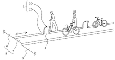
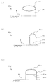
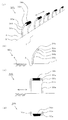
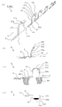
図1〜図9は本発明の実施の形態1に係る自転車レーンと歩行者レーンとの分離構造を説明するものであって、図1は全体を示す斜視図、図2の(a)および(b)は構成部材(Aタイプの鋼製ブロック)を示す正面視の断面図および斜視図、図3の(a)および(b)は構成部材(Bタイプの鋼製ブロック)を示す正面視の断面図および斜視図、図4の(a)、(b)および(c)は構成部材(Cタイプの鋼製ブロック)を示す正面視の断面図、斜視図および側面図、図5の(a)、(b)および(c)は構成部材(Dタイプの鋼製ブロック)、構成部材(Eタイプの鋼製ブロック)および構成部材(Fタイプの鋼製ブロック)を示す正面視の断面図、図6〜図9はそれぞれ構成部材(Aタイプの鋼製柵〜Dタイプの鋼製柵)を示すものであって、それぞれにおいて(a)、(b)、(c)および(d)は斜視図、正面図、側面図および平面図である。
なお、各図は模式的に示すものであって、本発明は図示された形態に限定されるものではない。
[Embodiment 1: Separation structure of bicycle lane and pedestrian lane]
FIGS. 1 to 9 illustrate a structure for separating a bicycle lane and a pedestrian lane according to
In addition, each figure is shown typically and this invention is not limited to the form shown in figure.
(分離構造)
図1において、自転車レーンと歩行者レーンとの分離構造(以下、「分離構造」と称す)1は、車道9から分離された既設の歩行者道8の歩行方向(←→にて示す)に沿って、所定の間隔4を空けて設置された複数の鋼製ブロック20と、間隔4に設置された鋼製柵30と、を有し、既設の歩行者道8をあらたな歩行者レーン6と自転車レーン7とに完全分離している。
(Separation structure)
In FIG. 1, a separation structure (hereinafter referred to as “separation structure”) 1 between a bicycle lane and a
したがって、自転車の走行と歩行者の歩行との錯綜による衝突事故が防止され、歩行者を巻き込んだ自転車の事故を抑えることが可能になる。
また、鋼製柵30が例えば600〜700mm程度の高さであるのに対し、その間に配置された鋼製ブロック20の高さは例えば80mm若しくは110mm程度と低いため、歩行者レーン6を歩行する際および自転車レーン7を走行する際の圧迫感がないから、歩行者レーン6に沿った市街の美観が向上する。
また、自転車運転者は、歩行者レーン6に立ち入ることが可能であるから、歩行者レーン6に沿った店舗等への出入りが容易になる。このとき、鋼製柵30の幅(歩行方向の長さ)を間隔4の幅(歩行方向の長さ)よりも小さく(例えば、前者を600mm程度、後者を3000mm程度)して、鋼製ブロック20と鋼製柵30との間に自転車のタイヤが通過する程度の隙間(例えば、100mm程度)を設けておけば、自転車を押して歩行者レーン6に容易に立ち入ることができる。
Therefore, it is possible to prevent a collision accident due to the complication of the traveling of the bicycle and the walking of the pedestrian, and to suppress the accident of the bicycle involving the pedestrian.
Moreover, since the
In addition, since the bicycle driver can enter the
また、従来のコンクリート縁石と相違して、鋼製ブロック20および鋼製柵30は軽量であって、既設の歩行者道8への固定に際して重機を必要とせず、施工が容易であるから、施工コストが安価になると共に施工期間が短縮する。さらに、既設の歩行者道8に固定された鋼製ブロック20および鋼製柵30は、撤去が容易であるから、鋼製ブロック20または鋼製柵30の部分的な更新や、歩行者レーン6や自転車レーン7の張り替え等に、迅速に対応することができる。
In addition, unlike the conventional concrete curb, the steel block 20 and the
(鋼製ブロック−Aタイプ)
図2において、鋼製ブロック20aは鋼板によって形成されたものであって、歩行方向に垂直な断面において、上面21aが歩行者道8に略平行(略平坦)で、上面21aの両側縁に連続した一対の側面22a同士の間隔が、下方になるほど広くなる略ハ字状であって、側面22aの下縁に連続して外側に向かって突出する側面フランジ23aが形成されている。また、歩行方向に平行な断面において、上面21aの両端縁に連続した一対の端面24a同士の間隔が、下方になるほど広くなる略ハ字状であって、端面24aの下縁に連続して外側に向かって突出する端面フランジ25aが形成されている。
なお、側面22aと端面24aとは略円弧状に滑らかに連続し(両者の境界が曖昧になっている)、側面フランジ23aと端面フランジ25aとは、上面21aに略平行な面内において連続している(両者の境界が曖昧になっている)。
さらに、側面フランジ23aには、鋼製ブロック20aを歩行者道8に固定するための、固定用ビス28aが貫通する複数の固定用孔26aが形成されている。なお、固定用孔26aの数量や配置形態は限定するものではなく、また、端面フランジ25aに形成してもよい。また、固定用ビス28aに替えて、固定用のボルト等を使用してもよい。
(Steel block-A type)
In FIG. 2, the
The
Further, a plurality of fixing
したがって、鋼製ブロック20aは、鋼板を張り出し加工(プレス加工)することによって容易に形成することができるから、製造コストが安価になる。
また、比較的薄い板厚であっても所定の剛性を有するから、軽量化を促進することが可能になり、運搬やハンドリングが容易且つ迅速になり、また、固定用ビス28aを打設するだけで、鋼製ブロック20aを歩行者道8に固定することができるから、施工が容易且つ迅速になり、鋼製ブロック20aを設置するための施工コストが安価になる。すなわち、歩行者道8の掘削や埋め戻し等が不要になるから、そのための機械と運転者とを準備する必要がなくなる。
さらに、固定用ビス28aを引き抜くだけで、鋼製ブロック20aを歩行者道8から撤去することができるから、特定の位置の鋼製ブロック20aを部分的に更新したり、所定の数量の鋼製ブロック20aをまとめて更新したりする作業が、容易かつ迅速になるから、このための施工コストが安価になる。
なお、鋼板の厚さや品種(降伏応力等)は限定するものではなく、また、塗装鋼板やステンレス鋼板等であってもよい。
さらに、鋼製ブロック20aは直線状であるものに限定するものではなく、自転車レーン7が平面視において曲がっている場合には、その曲率半径に応じて曲げられてもよい。
Therefore, the
In addition, since it has a predetermined rigidity even with a relatively thin plate thickness, it is possible to promote weight reduction, transportation and handling are easy and quick, and only a fixing
Furthermore, since the
The thickness and type (yield stress, etc.) of the steel plate are not limited, and may be a coated steel plate or a stainless steel plate.
Further, the
(鋼製ブロック−Bタイプ)
図3において、鋼製ブロック20bは、鋼製ブロック20aにおける平坦な側面22aおよび端面24aをそれぞれ階段状(コルゲート状)の階段側面22bおよび階段端面24bに形成したものである。したがって、鋼製ブロック20aと同じ作用効果が得られると共に、意匠性が向上する。また、剛性が向上するから鋼板の薄肉化を図ることができ、製造コストがさらに安価になる。
なお、階段状の形態は限定するものではなく、断面直線状や断面曲線状の何れであってもよく、折れ曲がる(屈曲する)数は限定されない。また、鋼製ブロック20aと同じ部分または相当する部分については、符号の数字を同じにして添え字を「a」に変更し、一部の説明を省略する。
(Steel block-B type)
In FIG. 3, a
Note that the stepped shape is not limited, and may be either a straight cross-sectional shape or a cross-sectional curved shape, and the number of bending (bending) is not limited. For the same or corresponding parts as the
(鋼製ブロック−Cタイプ)
図4において、鋼製ブロック20cは、歩行方向に垂直な断面において、平行した直線部21c、27cと、対向した一対の半円部22cとを有する扁平鋼管によって形成されたものであって、扁平鋼管の端部から所定の範囲が下方(歩行者道8側)に向かって折り曲げられ屈曲部24cと、屈曲部24cに連続した脚部25cとが形成されている。
そして、脚部25cが歩行者道8に侵入して、図示しない手段(例えば、モルタル等)によって、地盤に固定されている。
したがって、鋼製ブロック20cを扁平鋼管の曲げ加工によって形成することができるから、製造コストが安価になる。また、歩行者道8に小さな穴を掘って、そこに例えばモルタルを注入して、脚部25cを挿入するだけで施工することができるから、施工コストを安価に抑えることができる。
(Steel block-C type)
In FIG. 4, a
And the
Therefore, since the
このとき、下側の直線部27cは、歩行者道8に当接しても、隙間を介して浮き上がってもよい。当接した場合には、仕切られた後の歩行者レーン6と自転車レーン7との一方から他方に水、塵埃や落ち葉等が侵入し難くなり、一方、浮き上がった場合には、仕切られた後の歩行者レーン6と自転車レーン7との一方から他方に水等が侵入し易くなる(たとえば、歩行者レーン6に降り込んだ雨水が自転車レーン7を経由して車道9に流れ出し易くなる)。
なお、直線部21c、27cの長さあるいは半円部22cの曲率半径は限定するものではなく、また、直線部21c、27cを曲線、例えば、半円部22cの曲率半径より大きな曲率半径を有する円弧にしてもよい。そして、直線部21cと半円部22cの上半分を併せた範囲が「略円弧状の上面」を形成している。
At this time, the lower
Note that the length of the
(鋼製ブロック−Dタイプ)
図5の(a)において、鋼製ブロック20dは、鋼製ブロック20cの扁平鋼管に替えて楕円鋼管21dによって形成されたものである。したがって、扁平鋼管によって形成された鋼製ブロック20cと同じ作用効果を奏する。
なお、楕円の長軸を歩行者道8と平行にしても、あるいは、楕円の短軸を歩行者道8と平行にしてもよい。
(Steel block-D type)
In FIG. 5A, the
The major axis of the ellipse may be parallel to the
(鋼製ブロック−Eタイプ)
図5の(b)において、鋼製ブロック20eは、鋼製ブロック20cの扁平鋼管に替えて、歩行方向に垂直な断面において、円弧状の上面21eと、上面21eの両側縁に滑らかに連続した平行な一対の側面22eと、一対の側面22eの下縁同士を連結する下面27eと、を有する異形鋼管(以下、「甲丸鋼管」と称す)によって形成されている。したがって、扁平鋼管によって形成された鋼製ブロック20cと同じ作用効果を奏する。
なお、上面21eの曲率半径または楕円度(長軸と短軸との比率)、あるいは側面22eの大きさ(高さ)は限定するものではない。
図5の(c)に、鋼製ブロック20eにおける上面21eの曲率半径を小さく、且つ、側面22eを大きく(高く)した鋼製ブロック20fを示している。
(Steel block-E type)
In FIG. 5 (b), the
The radius of curvature or ellipticity (ratio of major axis to minor axis) of the
FIG. 5C shows a
(鋼製柵−Aタイプ)
図6において、鋼製柵30aは鋼管によって形成されたものであって、歩行方向および歩行者道8に平行な上部(以下、「梁部」と称す)31aと、梁部31aの両端に下方(歩行者道8側)に向かって折り曲げられた屈曲部32aと、屈曲部32aに連続した側部(以下、「柱部」と称す)33aとを有している。また、緩衝材34aが梁部31aの外周を包囲している。
そして、柱部33aの下端が、歩行者道8に挿入され、図示しない固定手段(例えば、モルタル等)によって固定されている。このとき、梁部31aは歩行者道8から600〜700mmの高さであって、十分に目立つから、歩行者および自転車運転者の両方に容易に視認される。
(Steel fence-A type)
In FIG. 6, a
And the lower end of the
したがって、歩行者レーン6と自転車レーン7との境目(以下、「レーン境界」と称す)5が強く認識され、歩行方向および走行方向が明瞭に示され、歩行および走行の安全性が向上する。
また、緩衝材34aが設置されているから、仮に、衝突しても緩衝され、歩行者および自転車運転者の打撲による怪我等が防止される。なお、梁部31a(緩衝材34aに同じ)に自転車を一時的に立て掛けることができるから、休憩の場所を提供することにもなる。
さらに、緩衝材34aの色彩、模様、厚さあるいは材質等は限定されるものではなく、レーン境界5をより際立たせる形態(例えば、光反射手段を貼付する等)にしたり、設置場所の環境により適合する形態にしたりすることができる。
なお、鋼管の断面形状は限定するものではなく、丸鋼管(真円、長円、楕円)、甲丸鋼管あるいは角鋼管であってもよい。また、鋼管に替えて溝形鋼(断面略U字状のチャンネル)であってもよい。さらに、緩衝材34aを撤去してもよい。
Therefore, the
In addition, since the
Further, the color, pattern, thickness, material, etc. of the
The cross-sectional shape of the steel pipe is not limited, and may be a round steel pipe (perfect circle, oval, ellipse), a round steel pipe, or a square steel pipe. Moreover, it may replace with a steel pipe and may be channel steel (channel with a substantially U-shaped cross section). Further, the
(鋼製柵−Bタイプ)
図7において、鋼製柵30bは、直線状の柱部33aを具備する鋼製柵30aにおいて、柱部33aの上範囲(梁部31aに近い範囲)を自転車レーン7側に突出するように曲げ加工して「柱傾斜部35b」を形成したものである。なお、鋼製柵30aと同じ部分または相当する部分には同じ符号を付し、一部の説明を省略する。
したがって、鋼製柵30bによって自転車運転者へのレーン境界5に対する注意が高まるから、歩行者の安全性がさらに向上する。なお、柱傾斜部35bは略円弧状であるものに限定するものではなく、直線状であってもよい。
(Steel fence-B type)
In FIG. 7, the
Therefore, since the
(鋼製柵−Cタイプ)
図8において、鋼製柵30cは、鋼製柵30bにおける一対の柱部33a(柱傾斜部35bを有する)の一方を撤去し片脚状態にしたものである。なお、鋼製柵30bと同じ部分または相当する部分には同じ符号を付し、一部の説明を省略する。
すなわち、鋼製柵30cは、一本の柱部33cと、柱傾斜部35bと、カンチレバー状(片持ち梁)状の梁部31c、とを有している。そして、例えば、梁部31cを白色にしておけば、単白線が浮いているかのように視認され、レーン境界5の方向性と連続性が明瞭に示されることになる。
(Steel fence-C type)
In FIG. 8, a
That is, the
よって、歩行者の自転車レーン7への侵入を抑制する雰囲気があり、また、自転車の歩行者レーン6への侵入を困難にする機能を備えている。
なお、鋼製柵30a(柱傾斜部35bを有しない)に準じて、柱傾斜部35bを具備しない形態であってもよい。
さらに、図8において、鋼製柵30cは、間隔4毎にそれぞれ1台が設置され、それぞれの梁部31cの先端の方向が同一方向を向いているが、本発明はこれに限定するものではない。例えば、間隔4毎にそれぞれ2台を設置し、それぞれの梁部31cの先端の方向を同一方向を向けたり、あるいはそれぞれの梁部31cの先端が向かい合う(対向する)ように方向を相違させたりしてもよい。
Therefore, there is an atmosphere that suppresses the intrusion of the pedestrian into the
In addition, the form which does not comprise the
Further, in FIG. 8, one
(鋼製柵−Dタイプ)
図9において、鋼製柵30dは、鋼製柵30aにおける一対の柱部33aの一方を撤去し片脚状態にすると共に、梁部31aを傾斜させて傾斜梁31dにしたものである(
鋼製柵30cにおいて、柱傾斜部35bを撤去して、梁部31cを傾斜させたものに相当する)。なお、鋼製柵30aと同じ部分または相当する部分には同じ符号を付し、一部の説明を省略する。
したがって、鋼製柵30cと同様に、レーン境界5の方向性と連続性が明瞭に示されることになり、歩行者の自転車レーン7への侵入を抑制する雰囲気があり、また、自転車の歩行者レーン6への侵入を困難にする機能を備えている。
なお、鋼製柵30c(柱傾斜部35bを有する)に準じて、柱傾斜部35bを具備する形態であってもよい。
(Steel fence-D type)
In FIG. 9, a
In the
Therefore, like the
In addition, the form which comprises the
[実施の形態2:自転車レーンと歩行者レーンとの分離構造]
図10は本発明の実施の形態2に係る自転車レーンと歩行者レーンとの分離構造を説明するものであって、(a)は全体を示す斜視図、(b)は構成部材(鋼製柵)を示す正面図、(c)は構成部材(鋼製柵)を示す側面図、(d)は構成部材(鋼製柵)を示す平面図である。なお、実施の形態1と同じ部分または相当する部分には同じ符号を付し、一部の説明を省略する。
[Embodiment 2: Separation structure of bicycle lane and pedestrian lane]
10A and 10B illustrate a structure for separating a bicycle lane and a pedestrian lane according to
(分離構造)
図10において、自転車レーンと歩行者レーンとの分離構造(以下、「分離構造」と称す)2は、車道9から分離された既設の歩行者道8の歩行方向(←→にて示す)に沿って設置された複数の鋼製柵40によって形成されている。なお、実施の形態1と同じ部分または相当する部分には同じ符号を付し、一部の説明を省略する。
(Separation structure)
In FIG. 10, the separation structure (hereinafter referred to as “separation structure”) 2 between the bicycle lane and the
(鋼製柵−Eタイプ)
図10において、鋼製柵40は鋼管によって形成されたものであって、歩行方向および歩行者道8に平行な上部(以下、「梁部」と称す)31aと、梁部31aの両端に下方(歩行者道8側)に向かって折り曲げられた屈曲部32aと、屈曲部32aに連続した側部(以下、「柱部」と称す)33a、43とを有している。柱部33aおよび柱部43は梁部31aに近い範囲に柱傾斜部35bが形成されている。
また、柱部33aの下端は延長され第1延長部39が形成され、柱部43の下端には梁部31aに平行な第2延長部(以下、「敷居部」と称す)47が接続されている。さらに、敷居部47の端部には傾斜した敷居傾斜部48が形成され、敷居傾斜部48の下方に、第1延長部39に平行な第3延長部49が接続されている。
(Steel fence-E type)
In FIG. 10, the
Further, the lower end of the
鋼製柵40は、複数の鋼管等を接合して形成してもよいし、1本の鋼管等を曲げ加工して形成してもよい。
すなわち、鋼製柵40は、実施の形態1に示された鋼製柵30bと鋼製ブロック20dとを一体化したものに相当している。したがって、分離構造2によって、実施の形態1に示す分離構造1と同様の作用効果が得られる。特に、必要な施工資材の種類が減小するため、製造コストが安価になると共に、施工資材の管理が容易になり、施工コストが安価になる。
The
That is, the
なお、実施の形態1に示された鋼製柵30a〜30dと鋼製ブロック20a〜20fとの一体化は、鋼製柵40(鋼製柵30bと鋼製ブロック20dとを一体化したものに相当する)に限定するものではなく、これ等を適宜組み合わせて一体化することができる。
図10において、分離構造2は、鋼製柵40の梁部31aおよび敷居部47の歩行方向の長さが、それぞれ略600mmであって、2台を同じ向きに配置している(一方の鋼製柵40の敷居傾斜部48と他方の鋼製柵40の柱部33aとが対向している。
The
In FIG. 10, in the
[実施の形態3:自転車レーンと歩行者レーンとの分離構造]
図11は本発明の実施の形態3に係る自転車レーンと歩行者レーンとの分離構造を説明する全体を示す斜視図である。なお、実施の形態2と同じ部分または相当する部分には同じ符号を付し、一部の説明を省略する。
図11において、自転車レーンと歩行者レーンとの分離構造(以下、「分離構造」と称す)3は、鋼製柵40の梁部31aおよび敷居部47の歩行方向の長さが、それぞれ略600mmおよび1500mmであって、2台毎に、反対の向きに配置されている(一方の鋼製柵40の敷居傾斜部48と他方の鋼製柵40の敷居傾斜部48とが対向している)。このとき、敷居部47と歩行者道8との間に隙間を設けて、レーン間を跨がった水等の侵入(例えば、排水や清掃等)を容易にしているが、敷居部47と歩行者道8とを密着させて、隙間を塞いでもよい。
したがって、実施の形態2に示す分離構造2と同様の作用効果を奏する。
[Embodiment 3: Separation structure of bicycle lane and pedestrian lane]
FIG. 11 is a perspective view illustrating the whole structure for separating a bicycle lane and a pedestrian lane according to Embodiment 3 of the present invention. In addition, the same code | symbol is attached | subjected to the part which is the same as that of
In FIG. 11, the separation structure (hereinafter referred to as “separation structure”) 3 of the bicycle lane and the pedestrian lane 3 has a length in the walking direction of the
Therefore, the same effect as the
本発明は以上の構成であるから、内部材の充填が容易になり施工コストの低減を図ることができるから、各種地形に応じた形状およびサイズに応じた自転車レーンと歩行者レーンとの分離構造、および該自転車レーンと歩行者レーンとの分離構造の施工方法として広く利用することができる。 Since the present invention has the above-described configuration, it is possible to easily fill the inner member and reduce the construction cost. Therefore, the bicycle lane and the pedestrian lane are separated from each other according to the shape and size according to various terrain. And a construction method of a separation structure of the bicycle lane and the pedestrian lane.
1 分離構造(実施の形態1)
2 分離構造(実施の形態2)
3 分離構造(実施の形態3)
4 間隔
5 レーン境界
6 歩行者レーン
7 自転車レーン
8 歩行者道
9 車道
20 鋼製ブロック
20a 鋼製ブロック
20b 鋼製ブロック
20c 鋼製ブロック
20d 鋼製ブロック
20e 鋼製ブロック
20f 鋼製ブロック
21a 上面
21c 直線部
21d 楕円鋼管
21e 上面
22a 側面
22b 階段側面
22c 半円部
22e 側面
23a 側面フランジ
24a 端面
24b 階段端面
24c 屈曲部
25a 端面フランジ
25c 脚部
26a 固定用孔
27c 直線部
27e 下面
28a 固定用ビス
30 鋼製柵
30a 鋼製柵
30b 鋼製柵
30c 鋼製柵
30d 鋼製柵
31a 梁部
31c 梁部
31d 傾斜梁
32a 屈曲部
33a 柱部
33c 柱部
34a 緩衝材
35b 柱傾斜部
35c 柱傾斜部
39 第1延長部
40 鋼製柵
43 柱部
47 敷居部(第2延長部)
48 敷居傾斜部
49 第3延長部
1 Separation structure (Embodiment 1)
2 Separation structure (Embodiment 2)
3 Separation structure (Embodiment 3)
4
48
Claims (11)
該フランジを貫通する固定手段によって、前記鋼製ブロックが前記歩行者道に固定されることを特徴とする請求項1記載の自転車レーンと歩行者レーンとの分離構造。 The steel block is formed of a steel plate, and in a cross section perpendicular to the walking direction, a linear or substantially arc-shaped upper surface, a substantially C-shaped side surface continuous to both side edges of the upper surface, and a lower edge of the side surface And a flange projecting outward continuously.
The structure for separating a bicycle lane and a pedestrian lane according to claim 1, wherein the steel block is fixed to the pedestrian road by a fixing means penetrating the flange.
前記鋼管の端部から所定の範囲が下方に向かって折り曲げられ、該折り曲げられた範囲の一部が前記歩行者道に埋設されることによって、前記鋼製ブロックが前記歩行者道に固定されることを特徴とする請求項1記載の自転車レーンと歩行者レーンとの分離構造。 The steel block is formed of a steel pipe, and the cross section perpendicular to the walking direction is straight or substantially arc-shaped on the upper surface,
A predetermined range is bent downward from an end of the steel pipe, and a part of the bent range is embedded in the pedestrian road, so that the steel block is fixed to the pedestrian road. The structure for separating a bicycle lane and a pedestrian lane according to claim 1.
前記上部に連続した一対の側部の下端から所定の範囲が、それぞれ前記歩行者道に埋設されることによって、前記鋼製ブロックが前記歩行者道に固定されることを特徴とする請求項1乃至4の何れかに記載の自転車レーンと歩行者レーンとの分離構造。 The steel fence is formed of a steel pipe, and the upper part is an inverted U shape having a planar shape or a substantially arc-shaped cross section,
2. The steel block is fixed to the pedestrian road by embedding predetermined ranges from the lower ends of a pair of side parts continuous to the upper part in the pedestrian road, respectively. The separation structure of the bicycle lane and pedestrian lane in any one of thru | or 4.
前記上部に連続した側部の下端から所定の範囲が、それぞれ前記歩行者道に埋設されることによって、前記鋼製ブロックが前記歩行者道に固定されることを特徴とする請求項1乃至4の何れかに記載の自転車レーンと歩行者レーンとの分離構造。 The steel fence is formed of a steel pipe, and the upper part is an inverted L shape parallel to the pedestrian path, or a substantially square shape that is farther from the pedestrian path as the tip of the upper part becomes the tip,
5. The steel block is fixed to the pedestrian road by embedding a predetermined range from the lower end of the side part continuous with the upper part in the pedestrian road, respectively. A separation structure of the bicycle lane and the pedestrian lane according to any one of the above.
前記鋼製柵が鋼管によって形成され、上部が略直線状の逆U字状であって、
前記上部に連続した一対の側部の一方の下端が下方に延長されて第1延長部が形成され、
前記上部に連続した一対の側部の他方の下端が前記歩行者道に平行で前記上部から遠ざかる方向に折り曲げられて第2延長部が形成され、
該第2延長部の端部が、前記第1延長部に平行になるように折り曲げられて第3延長部が形成され、
前記第1延長部および前記第3延長部の下端に近い所定範囲がそれぞれ前記歩行者道に埋設されることによって、前記鋼製ブロックが前記歩行者道に固定されることを特徴とする自転車レーンと歩行者レーンとの分離構造。 Having multiple steel fences installed along the walking direction of the pedestrian path,
The steel fence is formed of a steel pipe, and the upper part is a substantially straight inverted U shape,
The lower end of one of the pair of side parts continuous with the upper part is extended downward to form a first extension part,
The second lower end is formed by bending the other lower end of the pair of side parts continuous to the upper part in a direction parallel to the pedestrian path and away from the upper part,
A third extension is formed by bending an end of the second extension so as to be parallel to the first extension;
A bicycle lane characterized in that the steel blocks are fixed to the pedestrian road by embedding predetermined ranges close to the lower ends of the first extension part and the third extension part in the pedestrian road, respectively. And separation structure with pedestrian lane.
Priority Applications (1)
| Application Number | Priority Date | Filing Date | Title |
|---|---|---|---|
| JP2011054955A JP5762065B2 (en) | 2011-03-14 | 2011-03-14 | Separate structure of bicycle lane and pedestrian lane |
Applications Claiming Priority (1)
| Application Number | Priority Date | Filing Date | Title |
|---|---|---|---|
| JP2011054955A JP5762065B2 (en) | 2011-03-14 | 2011-03-14 | Separate structure of bicycle lane and pedestrian lane |
Publications (2)
| Publication Number | Publication Date |
|---|---|
| JP2012188892A true JP2012188892A (en) | 2012-10-04 |
| JP5762065B2 JP5762065B2 (en) | 2015-08-12 |
Family
ID=47082344
Family Applications (1)
| Application Number | Title | Priority Date | Filing Date |
|---|---|---|---|
| JP2011054955A Active JP5762065B2 (en) | 2011-03-14 | 2011-03-14 | Separate structure of bicycle lane and pedestrian lane |
Country Status (1)
| Country | Link |
|---|---|
| JP (1) | JP5762065B2 (en) |
Cited By (4)
| Publication number | Priority date | Publication date | Assignee | Title |
|---|---|---|---|---|
| JP2012197623A (en) * | 2011-03-22 | 2012-10-18 | Jfe Metal Products & Engineering Inc | Steel block structure and construction method thereof |
| JP2012197615A (en) * | 2011-03-22 | 2012-10-18 | Reiji Oshima | Footrest for two-wheel vehicle |
| JP2016199930A (en) * | 2015-04-13 | 2016-12-01 | 株式会社日立製作所 | Gate door control system |
| CN107190604A (en) * | 2017-05-24 | 2017-09-22 | 中建钢构有限公司 | A kind of bicycle expressway girder steel paving structure and its paving method |
Citations (5)
| Publication number | Priority date | Publication date | Assignee | Title |
|---|---|---|---|---|
| JPS4715438U (en) * | 1971-03-22 | 1972-10-23 | ||
| JPS63100513U (en) * | 1986-12-19 | 1988-06-30 | ||
| JPH0351405A (en) * | 1989-07-19 | 1991-03-05 | Nippon Mektron Ltd | Method and device for constituting center divisional strip for facing two-lane road |
| JP3152928U (en) * | 2009-05-21 | 2009-08-20 | 光海陸産業株式会社 | Greening combined fence |
| JP2010174587A (en) * | 2009-02-02 | 2010-08-12 | Ito Yogyo Co Ltd | Road facility |
-
2011
- 2011-03-14 JP JP2011054955A patent/JP5762065B2/en active Active
Patent Citations (5)
| Publication number | Priority date | Publication date | Assignee | Title |
|---|---|---|---|---|
| JPS4715438U (en) * | 1971-03-22 | 1972-10-23 | ||
| JPS63100513U (en) * | 1986-12-19 | 1988-06-30 | ||
| JPH0351405A (en) * | 1989-07-19 | 1991-03-05 | Nippon Mektron Ltd | Method and device for constituting center divisional strip for facing two-lane road |
| JP2010174587A (en) * | 2009-02-02 | 2010-08-12 | Ito Yogyo Co Ltd | Road facility |
| JP3152928U (en) * | 2009-05-21 | 2009-08-20 | 光海陸産業株式会社 | Greening combined fence |
Cited By (7)
| Publication number | Priority date | Publication date | Assignee | Title |
|---|---|---|---|---|
| JP2012197623A (en) * | 2011-03-22 | 2012-10-18 | Jfe Metal Products & Engineering Inc | Steel block structure and construction method thereof |
| JP2012197615A (en) * | 2011-03-22 | 2012-10-18 | Reiji Oshima | Footrest for two-wheel vehicle |
| JP2016199930A (en) * | 2015-04-13 | 2016-12-01 | 株式会社日立製作所 | Gate door control system |
| CN107190604A (en) * | 2017-05-24 | 2017-09-22 | 中建钢构有限公司 | A kind of bicycle expressway girder steel paving structure and its paving method |
| WO2018214985A1 (en) * | 2017-05-24 | 2018-11-29 | 中建钢构有限公司 | Steel girder pavement structure for high-speed road for bicycle, and roadbed pavement method therefor |
| CN107190604B (en) * | 2017-05-24 | 2019-11-05 | 中建钢构有限公司 | A kind of bicycle expressway girder steel paving structure and its paving method |
| US11124924B2 (en) | 2017-05-24 | 2021-09-21 | China Construction Steel Structure Corp. Ltd. | Steel girder pavement structure for high-speed road for bicycle, and roadbed pavement method therefor |
Also Published As
| Publication number | Publication date |
|---|---|
| JP5762065B2 (en) | 2015-08-12 |
Similar Documents
| Publication | Publication Date | Title |
|---|---|---|
| KR100952610B1 (en) | Extension footpath for a bridge | |
| JP5762065B2 (en) | Separate structure of bicycle lane and pedestrian lane | |
| JP6347088B2 (en) | Concrete slab structure and precast concrete slab | |
| KR101083303B1 (en) | Prefabricated extension sidewalk for bridge | |
| CN105971005A (en) | Open cut method large-span two-arch two-cable subway station structure | |
| KR102035821B1 (en) | Guard rail for preventing jaywalking and construction method for the same | |
| KR101307290B1 (en) | Guardrail structure and installation thereof | |
| KR101231559B1 (en) | Safety pence | |
| JP6614655B2 (en) | A new road formation method with a bicycle lane using a free-gradient gutter | |
| KR101489965B1 (en) | Safety fences with easy maintenance | |
| JP5713765B2 (en) | Bicycle lane and pedestrian lane separation system using steel blocks | |
| KR101355843B1 (en) | Guard fence reinforcing structure and method of installing thereof | |
| JP2006233669A (en) | Method of widening bridge sidewalk, and bridge sidewalk structure | |
| KR101861570B1 (en) | Durable, expandable footbridge | |
| JP2015057541A (en) | Separation system of bicycle lane and pedestrian lane by steel blocks | |
| KR20150024195A (en) | Haunch members unit containing drain holes and bridge structure by using of it | |
| KR101109128B1 (en) | Footbridge having reinforcement structure | |
| JP2011021402A (en) | Simple drain member, simple drain apparatus and construction method of the apparatus | |
| KR101021832B1 (en) | Floor panel for extension footpath | |
| JP3186328U (en) | Removable curb block and concrete gutter | |
| KR200476485Y1 (en) | Drainage structure | |
| KR101222161B1 (en) | Independent type girder bridge using pipe support | |
| KR20090121626A (en) | Change type pavement structure | |
| KR101278584B1 (en) | A prefabricated drain-road and executing the same | |
| JP6884477B2 (en) | Guard for median strip |
Legal Events
| Date | Code | Title | Description |
|---|---|---|---|
| A621 | Written request for application examination |
Free format text: JAPANESE INTERMEDIATE CODE: A621 Effective date: 20140110 |
|
| A977 | Report on retrieval |
Free format text: JAPANESE INTERMEDIATE CODE: A971007 Effective date: 20140825 |
|
| A131 | Notification of reasons for refusal |
Free format text: JAPANESE INTERMEDIATE CODE: A131 Effective date: 20150127 |
|
| A521 | Request for written amendment filed |
Free format text: JAPANESE INTERMEDIATE CODE: A523 Effective date: 20150318 |
|
| TRDD | Decision of grant or rejection written | ||
| A01 | Written decision to grant a patent or to grant a registration (utility model) |
Free format text: JAPANESE INTERMEDIATE CODE: A01 Effective date: 20150602 |
|
| A61 | First payment of annual fees (during grant procedure) |
Free format text: JAPANESE INTERMEDIATE CODE: A61 Effective date: 20150609 |
|
| R150 | Certificate of patent or registration of utility model |
Ref document number: 5762065 Country of ref document: JP Free format text: JAPANESE INTERMEDIATE CODE: R150 |
|
| S531 | Written request for registration of change of domicile |
Free format text: JAPANESE INTERMEDIATE CODE: R313531 |
|
| R350 | Written notification of registration of transfer |
Free format text: JAPANESE INTERMEDIATE CODE: R350 |
|
| R250 | Receipt of annual fees |
Free format text: JAPANESE INTERMEDIATE CODE: R250 |
|
| R250 | Receipt of annual fees |
Free format text: JAPANESE INTERMEDIATE CODE: R250 |
|
| R250 | Receipt of annual fees |
Free format text: JAPANESE INTERMEDIATE CODE: R250 |
|
| R250 | Receipt of annual fees |
Free format text: JAPANESE INTERMEDIATE CODE: R250 |
|
| R250 | Receipt of annual fees |
Free format text: JAPANESE INTERMEDIATE CODE: R250 |
|
| R250 | Receipt of annual fees |
Free format text: JAPANESE INTERMEDIATE CODE: R250 |