JP2012183714A - Ink bag, ink bag storage case, and ink cartridge - Google Patents
Ink bag, ink bag storage case, and ink cartridge Download PDFInfo
- Publication number
- JP2012183714A JP2012183714A JP2011048201A JP2011048201A JP2012183714A JP 2012183714 A JP2012183714 A JP 2012183714A JP 2011048201 A JP2011048201 A JP 2011048201A JP 2011048201 A JP2011048201 A JP 2011048201A JP 2012183714 A JP2012183714 A JP 2012183714A
- Authority
- JP
- Japan
- Prior art keywords
- ink
- bag
- ink bag
- fixing
- plate
- Prior art date
- Legal status (The legal status is an assumption and is not a legal conclusion. Google has not performed a legal analysis and makes no representation as to the accuracy of the status listed.)
- Granted
Links
Images


Abstract
Description
本発明は、インクジェットプリンターにインクを供給するインク袋、インク袋収納ケースおよびそのインク袋を搭載するインクカートリッジに関する。 The present invention relates to an ink bag for supplying ink to an inkjet printer, an ink bag storage case, and an ink cartridge on which the ink bag is mounted.
インクジェットプリンターは大量印刷、幅広化、高速化の要求に対応するために、インクジェットヘッドから独立したインク供給源を設け、インク供給源よりチューブを介してインクを供給する方式を採用し、インク供給源としてインク袋が用いられることがある。 Inkjet printers employ an ink supply source that is independent of the inkjet head and supplies ink via a tube from the ink supply source in order to meet the demands for mass printing, widening, and speeding up. As an example, an ink bag may be used.
前記のような構成のインクジェットプリンターの一例として、インク袋をハードケースに収納してインクカートリッジを構成すると共に、インク袋の一端に設けられたインク供給口をチューブに接続し、チューブを介してインクをインクジェットヘッドまで導入し、インクジェットヘッドまでインクを供給する構成が挙げられ、さらにインクカートリッジとインクジェットヘッドの間にサブタンクを設け、インク袋のインクが尽きても直ちにインクジェットヘッドへのインクの供給が停止しない構成も可能である。 As an example of the ink jet printer configured as described above, an ink bag is housed in a hard case to form an ink cartridge, and an ink supply port provided at one end of the ink bag is connected to a tube, and the ink is supplied via the tube. Can be introduced to the ink jet head, and ink can be supplied to the ink jet head. Furthermore, a sub tank is provided between the ink cartridge and the ink jet head, and the ink supply to the ink jet head stops immediately even if the ink in the ink bag is exhausted. A configuration without this is also possible.
このようなインク供給形態を構成すると、インクジェットプリンターにおけるインクカートリッジの収納位置の選択可能範囲が増すと共に、インクジェットプリンターへの大量印刷、幅広化、高速化の要求に応えるインクカートリッジの容量の拡大も容易となり、結果としてインクカートリッジの大型化、長大化が採られるようになった。 When such an ink supply mode is configured, the selectable range of the ink cartridge storage position in the ink jet printer is increased, and the capacity of the ink cartridge can be easily expanded to meet the demand for mass printing, widening, and high speed on the ink jet printer. As a result, the size and length of the ink cartridge have been increased.
ところで、このようなインクカートリッジには特許第3381789号に見られるように、インク袋のインク取出口をケースの固定溝形状に合わせた嵌合部を持ちインク取出口を高精度に位置決めするものがある。 By the way, as shown in Japanese Patent No. 338789, such an ink cartridge has a fitting portion in which the ink outlet of the ink bag is matched with the shape of the fixed groove of the case and positions the ink outlet with high accuracy. is there.
密閉型のインク袋を使用するインクカートリッジは収納していたインクがなくなると、インク袋とケースを含むインクカートリッジ全体を廃棄していた。しかし、インクがなくなったインク袋は再利用不可能だが、インクカートリッジのケースは再利用できるだけの機能を維持しており、ランニングコスト低減や省資源の観点から再利用可能な部品は繰返し使用できることが望まれた。しかし、インク袋は振動や落下を受けてもケースから脱落しないように強固に両面テープで固定されており、その結果、インク袋をケースから外すことは手間と困難をともなうという問題があった。さらにインクが充填されたインク袋は形が定まらない状態であるが、ケースに対して所定の位置決め精度で取り付けないとインク袋がシワになったり歪んだりして最後までインクを消費することができなくなってしまい、結果としてインクを無駄にすることになる。またインク袋にはインク袋内のインク残量を検知するためにインクエンド検出板を有しており、ケースに対してインク袋を高精度に位置決めできないと、インクエンド検出も機能しなくなる恐れがある。これらもケースの再利用の問題となっていた。 When the ink cartridge that uses the sealed ink bag runs out of ink, the entire ink cartridge including the ink bag and the case is discarded. However, ink bags that have run out of ink cannot be reused, but the ink cartridge case maintains the functions that can be reused, and reusable parts can be used repeatedly from the viewpoint of reducing running costs and saving resources. Wanted. However, the ink bag is firmly fixed with double-sided tape so that it does not fall out of the case even if it is subjected to vibration or dropping, and as a result, there is a problem that it is troublesome and difficult to remove the ink bag from the case. Furthermore, the ink bag filled with ink is in a state where the shape is not fixed, but if it is not attached to the case with a predetermined positioning accuracy, the ink bag will be wrinkled or distorted and the ink can be consumed to the end. As a result, the ink is wasted. Also, the ink bag has an ink end detection plate for detecting the remaining amount of ink in the ink bag, and if the ink bag cannot be positioned with high accuracy with respect to the case, the ink end detection may not function. is there. These were also problems of case reuse.
本発明は前記問題に対し、インク袋固定について脱着の簡略化と高い位置決め精度を両立する構造を採用することで、ケースを再利用しインク袋のみを交換可能とするインク袋収納ケース、インク袋およびそのインク袋を搭載したインクカートリッジを提供することを目的とする。 In order to solve the above problem, the present invention adopts a structure that simplifies detachment and high positioning accuracy for fixing an ink bag, and thereby an ink bag storage case and an ink bag that can reuse the case and replace only the ink bag. It is another object of the present invention to provide an ink cartridge equipped with the ink bag.
上記の目的を達成するために、本発明のインク袋は、インクを貯蔵する可撓性を有する密閉袋と、前記密閉袋の一端に外部にインクを供給するインク供給口と、を有するインク袋において、前記密閉袋の一方の面であって前記密閉袋の長手方向の中央を含む位置に固定され、外部に配置された位置決め面と対向することで位置決めするスライド面を有し少なくとも前記位置決め面と前記スライド面とを対向させることで少なくとも1方向の位置決めが可能な固定板を有することを特徴とする。 In order to achieve the above object, an ink bag according to the present invention includes a flexible sealed bag for storing ink, and an ink supply port for supplying ink to one end of the sealed bag. And having a slide surface that is fixed by being opposed to a positioning surface that is arranged on the outside and that is fixed to a position that is one surface of the hermetic bag and includes the center in the longitudinal direction of the hermetic bag. And a fixed plate capable of positioning in at least one direction by facing the slide surface.
また、本発明のインク袋収納ケースは、上述インク袋を格納するインク袋格納ケースであって、上述インク袋のインク供給口を固定する口固定部と、上述インク袋のスライド面と対向する位置決め面と、を有することを特徴とする。 The ink bag storage case of the present invention is an ink bag storage case for storing the above-described ink bag, and includes a mouth fixing portion for fixing the ink supply port of the above-mentioned ink bag and a positioning facing the slide surface of the above-mentioned ink bag. And a surface.
また、本発明のインクカートリッジは、上述インク袋収納ケースに上述インク袋を格納したことを特徴とする。 The ink cartridge of the present invention is characterized in that the ink bag is stored in the ink bag storage case.
本発明の固定板をインク袋に設けることにより、ケースの再利用にともなうインク袋交換において、インク袋をケースに対して高精度な位置決め、固定機能と脱着作業の省力化を両立するインクカートリッジを提供できる。 By providing the fixing plate of the present invention in the ink bag, an ink cartridge that achieves both high-precision positioning of the ink bag with respect to the case, the fixing function, and labor saving of the detaching operation when the ink bag is replaced when the case is reused. Can be provided.
[実施の形態の概要]
次に本発明の実施の形態を説明する。インクカートリッジは、インク袋をケースに取付けた状態のときはケース外部にインクを供給可能にしつつ、インク袋は固定板を介してケースに固定、収納している。固定板はインク袋長手方向の略中央に位置しており、インク袋の姿勢を安定させインク消費量にともなうインク袋の収縮における形状変化のバラツキを小さくする機能がある。インク袋は一端にインク供給口を備え、かつ可撓性を有する。さらにインク袋の固定板とは反対の略平面にインク残量を検知するためのインクエンド検出板を有している。インクカートリッジのケースはメインケースとサブケースの少なくとも二体で構成されており、メインケースとサブケースを分離可能である。またはサブケースはメインケースと一体化されており、サブケースがメインケース上を移動可能な構造でも良い。なお、サブケースはメインケースとインク袋の嵌合部の固定をするため、少なくともインク供給口と固定板を覆う範囲だけの大きさがあればよい。したがって、サブケースはメインケースより小さくても良く、さらにインク供給口付近、固定板付近ごとに複数のサブケースで構成しても良い。
[Outline of the embodiment]
Next, an embodiment of the present invention will be described. When the ink bag is attached to the case, the ink cartridge allows the ink to be supplied to the outside of the case, and the ink bag is fixed and stored in the case via a fixing plate. The fixing plate is positioned substantially at the center in the longitudinal direction of the ink bag, and has a function of stabilizing the posture of the ink bag and reducing variation in shape change due to shrinkage of the ink bag due to ink consumption. The ink bag has an ink supply port at one end and has flexibility. Furthermore, an ink end detection plate for detecting the remaining amount of ink is provided on a substantially plane opposite to the fixing plate of the ink bag. The case of the ink cartridge is composed of at least two of a main case and a sub case, and the main case and the sub case can be separated. Alternatively, the sub case may be integrated with the main case, and the sub case may be movable on the main case. Since the sub case fixes the fitting portion between the main case and the ink bag, the sub case only needs to have a size that covers at least the ink supply port and the fixing plate. Therefore, the sub case may be smaller than the main case, and may be composed of a plurality of sub cases near the ink supply port and near the fixing plate.
固定板はメインケースと嵌合可能な構造が必要となるが、固定板は使用済みインク袋と共に再利用されないため極力単純な構造が望ましい。このような固定板は低コストで生産できる。したがって、固定板は板金または樹脂製の板を抜き加工しただけの平面的な形状がよい。しかし、固定板はインク袋と共に廃棄されるため環境問題の観点から、インク袋と固定板は同系統の材料より構成されていることが望ましい。インク袋は少なくともポリエチレン、ポリプロピレン、ポリエチレンテレフタレート、ナイロン、ポリ塩化ビニル、ポリ塩化ビニリデン、ポリビニルアルコール、共重合体エチレンビニルアルコールの樹脂の少なくとも一種類を含む樹脂フィルムより構成されているため、固定板も同種の樹脂製の板が理想的である。インク袋は複数の異なる樹脂層が含まれて構成されている場合は、その内の一つの樹脂で固定板を構成することが好ましい。 The fixing plate needs to have a structure that can be fitted to the main case. However, since the fixing plate is not reused together with the used ink bag, a simple structure is desirable. Such a fixing plate can be produced at low cost. Therefore, the fixed plate preferably has a planar shape obtained by punching a sheet metal or a resin plate. However, since the fixing plate is discarded together with the ink bag, the ink bag and the fixing plate are preferably made of the same material from the viewpoint of environmental problems. Since the ink bag is composed of a resin film containing at least one of polyethylene, polypropylene, polyethylene terephthalate, nylon, polyvinyl chloride, polyvinylidene chloride, polyvinyl alcohol, and copolymer ethylene vinyl alcohol, the fixing plate is also The same type of resin plate is ideal. In the case where the ink bag is configured to include a plurality of different resin layers, it is preferable that the fixing plate is configured by one resin among them.
インク袋はメインケースに位置決め、固定されており、サブケースを外すことによってメインケースからインク袋を取り外せる状態になる。インク袋はメインケースと、(1)インク袋の一端のインク供給口に設けられた嵌合構造と、メインケースの溝構造による嵌合、(2)インク袋の略中央に位置する固定板に設けられた嵌合構造と、メインケースの溝構造による嵌合、(3)インク袋尾部に設けられた穴と、メインケースの一部であるインク袋尾部の穴を引掛ける突起を有しインク袋の尾部をインク袋の長手方向に引き伸ばす方向に引っ張る引き込み構造を含む固定、これらの三箇所で固定されている。したがって固定板の位置はインク袋一端のインク供給口とインク袋他端の尾部の中間であるインク袋長手方向の略中央が望ましい。 The ink bag is positioned and fixed to the main case, and the ink bag can be removed from the main case by removing the sub case. The ink bag has a main case, (1) a fitting structure provided in an ink supply port at one end of the ink bag, and a fitting by a groove structure of the main case, and (2) a fixing plate positioned substantially at the center of the ink bag. A fitting structure provided, a fitting by a groove structure of the main case, (3) an ink having a hole provided in the tail portion of the ink bag and a protrusion for hooking a hole in the tail portion of the ink bag which is a part of the main case Fixing including a pull-in structure that pulls the tail of the bag in the direction of extending the longitudinal direction of the ink bag is fixed at these three locations. Therefore, the position of the fixing plate is preferably approximately the center in the longitudinal direction of the ink bag, which is intermediate between the ink supply port at one end of the ink bag and the tail at the other end of the ink bag.
インクジェットプリンターの使用にともないインク袋内のインクを消費し、インク袋の体積が徐々に小さくなり、これに従いインクエンド検出板が移動する。インク袋内のインクがなくなるときに達したインクエンド検出板の位置をインクジェットプリンターに設けられたインクエンド検出機構が検知し、インクジェットプリンターはインクエンドを検出する。インクジェットプリンターはインクエンドに達したインク袋を検出すると同時に、オペレーションパネルやインクエンド通知手段によってインクエンドの通知とインクエンドに達したインク袋の交換を促す。 As the ink jet printer is used, the ink in the ink bag is consumed, the volume of the ink bag is gradually reduced, and the ink end detection plate moves accordingly. The ink end detection mechanism provided in the ink jet printer detects the position of the ink end detection plate reached when the ink in the ink bag runs out, and the ink jet printer detects the ink end. The ink jet printer detects the ink bag that has reached the ink end, and at the same time, notifies the ink end notification and the replacement of the ink bag that has reached the ink end by the operation panel and the ink end notification means.
インク袋を取り外すときは、まずインクカートリッジを構成している部品をインクジェットプリンターから取り外す。インクジェットプリンターから取り外したインクカートリッジは最初にサブケースを取り外す。次にインク尾部の固定を解除し、インク袋全体をインク供給口方向にたわませることにより固定板、インク供給口の順に固定部を外すことができる。これによりインク袋に取り付けられた固定板とインクエンド検出板と共にインク袋がメインケースから取り外せる状態になる。 When removing the ink bag, first, the parts constituting the ink cartridge are removed from the ink jet printer. For the ink cartridge removed from the ink jet printer, first remove the sub case. Next, the fixing of the ink tail portion is released, and the fixing portion can be removed in the order of the fixing plate and the ink supply port by deflecting the entire ink bag in the direction of the ink supply port. As a result, the ink bag can be removed from the main case together with the fixing plate and the ink end detection plate attached to the ink bag.
新しいインク袋を取付けるときは、インク袋を取り外す時と逆の手順となる。最初にインク供給口の嵌合構造とメインケースの溝構造を嵌合させ、次に固定板の嵌合構造とメインケースの溝構造を略嵌合させ、最後にインク袋尾部の穴を引き込み構造により固定すると共にインク袋が引き伸ばされ固定板の嵌合が完了する。最後にサブケースをメインケースに取り付け、インクカートリッジのインク袋交換が完了する。 When installing a new ink bag, the procedure is the reverse of removing the ink bag. First, the ink supply port fitting structure and the main case groove structure are fitted, then the fixing plate fitting structure and the main case groove structure are substantially fitted, and finally the ink bag tail hole is pulled in. And the ink bag is stretched to complete the fitting of the fixing plate. Finally, the sub case is attached to the main case, and the ink bag replacement of the ink cartridge is completed.
なお、新しいインク袋にはあらかじめ固定板とインクエンド検出板が取り付けられており、インク袋またはインク袋と一体化された部品上に収納されているインクの種類、色、容量などインク情報が記載されている。さらに収納されているインクの種類、色、容量などインク情報が表示されているインク情報表示部を複数持ち、少なくともひとつのインク情報表示部はインク袋から分離可能な構造となっており、インク袋を収納するケースに取り付け可能な構造としてもよい。これによりインクカートリッジをインクジェットプリンター取り付け後であってもインク袋に収納されているインクの種類などインク情報を確認可能となっている。 The new ink bag has a fixed plate and an ink end detection plate attached in advance, and ink information such as the type, color, and capacity of the ink stored on the ink bag or a part integrated with the ink bag is described. Has been. Furthermore, it has a plurality of ink information display portions displaying ink information such as the type, color, and capacity of the ink stored, and at least one ink information display portion has a structure that can be separated from the ink bag. It is good also as a structure attachable to the case which accommodates. Thereby, even after the ink cartridge is attached to the ink jet printer, the ink information such as the type of ink stored in the ink bag can be confirmed.
さらにインク袋には収納しているインクの種類、色、容量などインク情報が電気、磁気、物理形状的に記録されているインク情報記録部を添付しても良い。インク情報記録部はメインケースとサブケースを分離したときに嵌合、固定される構造を持ちケースと一体化可能となっており、インクカートリッジ挿入時にインクジェットプリンターへインク情報を伝達できる。また、ひとつのインク袋とひとつのインク情報記録部の組合せに限らず、複数のインク袋とひとつのインク情報記録部の組合せとしても良い。 Furthermore, an ink information recording unit in which ink information such as the type, color, and capacity of ink stored in the ink bag is recorded in electrical, magnetic, and physical shapes may be attached. The ink information recording unit has a structure that is fitted and fixed when the main case and the sub case are separated from each other and can be integrated with the case, and can transmit ink information to the ink jet printer when the ink cartridge is inserted. Further, the combination is not limited to one ink bag and one ink information recording unit, and may be a combination of a plurality of ink bags and one ink information recording unit.
あるいはインクカートリッジのケースの一部はインクジェットプリンターと一体化しており、インク袋交換時はインクカートリッジをインクジェットプリンターより引き出し、ケースをインクジェットプリンターに保持させたままインク袋を交換する構造としても良い。 Alternatively, a part of the case of the ink cartridge may be integrated with the ink jet printer, and when replacing the ink bag, the ink cartridge may be pulled out from the ink jet printer, and the ink bag may be replaced while the case is held by the ink jet printer.
[実施の形態の詳細]
図1は本発明を適用したインクカートリッジの分解した状態の一実施形態の斜視図を、図2は図1で示した一実施形態の断面図を示す。インク袋10は、インクを封入する可撓性を持った材料で構成された扁平形状の袋である密閉袋11を含む。インク袋10は密閉容器であり、インクが充填されているときには膨らんだ状態で、インクが減少すると、それにあわせてインク袋10は収縮する。インク袋10の一端は、インクを出し入れするインク供給口12が備わっている。これは密閉袋11の一端にインクを排出する機能を持ち樹脂成型品で構成されたインク供給口12を熱溶着などの方法で一体化したものである。
[Details of the embodiment]
1 is a perspective view of an embodiment of an exploded state of an ink cartridge to which the present invention is applied, and FIG. 2 is a cross-sectional view of the embodiment shown in FIG. The
図示されていない検出機構を用いてインクエンドを検出する検出板14がインク袋10の表面に取付けられている。インク袋10内のインクの容量に応じてインク袋10は収縮するが、それに合わせて検出板14も移動する。インク袋10内のインクが減少し、検出板14が所定の位置に達した事を検知することで、インクカートリッジのエンプティを検出する。検出板14は、両面テープあるいは接着剤を用いてインク袋10の一方側の面に密着させて貼り付けることが好ましい。本実施例では検出板14は固定板20に対して対向する位置からずれた位置にあり、インク袋10をインク袋収納ケース30取り付け時に固定板20のスライド面がインク袋収納ケース30の位置決め面との位置決めの確認を容易にしている。しかし検出板14と固定板20を対向する位置に配置しても機能上は問題ない。
A
インク袋10は1枚の単層または2枚以上の多層樹脂フィルムの周辺部を熱溶着して袋状にしたものである。また、インク袋10はアルミフィルムを含む多層樹脂フィルムや複数種類の樹脂より構成してもよい。溶着部はインク袋10の周囲にインク漏れしないように十分な強度となる幅で溶着されている。
The
インク袋10上の検出板14取り付面と密閉袋11を挟む面に両面テープあるいは接着剤を用いて固定板20が取り付けられている。固定板20はインク袋10の面に密着しており、インク袋10とは容易に分離できない密着強度を有している。固定板20はインク袋10長手方向となるX方向の略中央にあり、インク袋10に対して所定の位置にあるように組み立てられており、固定板20の位置を基準にインク袋10の位置出しが可能となっている。また固定板20はインク袋10の姿勢が水平、垂直となっても支持できるだけの剛性を備えている。固定板20は射出成形による樹脂部品としてもよいが、樹脂板を打ち抜いて製造する方法のほうが好ましい。
A fixing
固定孔13はインク袋10長手方向となるX方向のインク供給口12と異なる端部にあり、インク袋短手方向となるY方向に2個設けてある。2個の固定孔13の位置はインク袋10の長手方向中心軸を対称軸とする対称位置にあり、固定孔13にバネ32とバネ固定部31を介して付勢することによりインク袋10が短手方向となるY方向に歪むことなく長手方向中心軸に対称形状の姿勢を維持できる。また実施例の固定孔13の形状は四角形や異形状でも良いが、バネ固定部31を介して付勢されるため破損しにくい形状が望ましい。固定孔13の望ましい形状として円形状があげられる。さらにインク袋10のインク供給口12と固定孔13はX方向とY方向に直交するZ方向の位置が等しくなるように位置決めするのが望ましい。
The fixing holes 13 are located at different ends from the
インク袋収納ケース30はインク袋10を収納可能な形状と、インク袋10を固定する機能をそなえている。一般的なインクカートリッジはインク袋10を露出しない構造となっているが、インクの量を目視で確認できるようにインク袋収納ケース30の一部を切り欠いてもよい。インク袋10のインク供給口12近傍はインク供給口12に設けられた溝部と、インク袋収納ケース30上に設けられた口固定部33が勘合することでインク袋収納ケース30に対してX方向の位置決めと固定がされる。
The ink
インク袋収納ケース30は固定板20を位置決めするための位置決め面となるa1面50、a2面51、a3面52、a4面53が設けられており、対向する位置に固定板20のスライド面となるb1面60、b2面61、b3面62、b4面63が位置する構造となっている。実施例では固定板20は略長方形状の板であり、広大面のうちの一面となるb1面60がインク袋収納ケース30上のa1面50に対向し、−Z方向の位置決めとなる。さらにもうひとつの広大面となるb2面61がインク袋10取り付面となり、b2面61上には図示していない両面テープが設けられており、固定板20とインク袋10を強固に固定している。また固定板20とインク袋10の固定に接着剤や加熱溶融する材料を用いてもよい。さらにインク袋収納ケース30内側の広大面となる位置決め面a1面50と、a1面50の周囲4辺に位置する壁面のうちインク袋10の長手方向と平行なa4面53がある。a3面53はa1面50とa4面53に直角な面であり、その結果、a1面50とb1面60が、a2面51とb2面61が対となって、インク袋収納ケース30と固定板20を図の上下方向となるZ方向の位置決めを可能としている。さらにY方向と直角をなす二組のa4面53とb4面63が対向し、インク袋10の短手方向となるY方向の位置決めを実現している。またインク袋収納ケース30のa3面52と固定板20のb3面62が対向し、インク袋10長手方向の一方向だけとなる+X方向の位置を規制することができる。本実施例ではa1面50とa2面51と、b1面60とb2面61が平行をなし、a1面50とa3面52と、a1面50とa4面53と、b1面60とb3面62と、b1面60とb4面63とが直角をなし、さらにa3面52とa4面53と、b3面62とb4面63も直角をなす関係にある。
The ink
図3は本発明を適用したインクカートリッジを分解した状態のもうひとつの実施形態の斜視図を、図4は図3で示したもうひとつの実施形態の断面図を示す。インク袋110は密閉袋111、インク供給口112、固定板120より構成されている。なお、図3、図4では検出板を図示していないが、検出板を設けてもよい。図1に示した実施例と異なる点は固定板120が平板状ではなくインク袋収納ケース130側に凸となるふたつの腕部121を持つコの字型断面の構造となっており、腕部121の根元にはインク袋110の長手方向となるX方向に切り欠きがある。固定板120にはインク袋110を支えるだけの強度や剛性が必要となり、射出成形による樹脂部品、樹脂板を打ちぬいた後に加熱して曲げる製法が望ましい。または固定板120は金属板を打ちぬき、曲げ加工した製法でも製造可能である。
FIG. 3 is a perspective view of another embodiment in which the ink cartridge to which the present invention is applied is disassembled, and FIG. 4 is a cross-sectional view of the other embodiment shown in FIG. The
インク袋収納ケース130は固定板120を位置決めするための位置決め面となるa11面150、a12面151、a13面152、a14面153、a15面154を持ち、対向する位置に固定板120の非腕部の広大面のうちインク袋収納ケース130に対向するスライド面のb11面160、腕部121上の切り欠きを構成する面のうちb11面160に平行かつ向かい合う向きにあるb12面161、腕部121上の切り欠きを構成する面のうちb11面160と直角をなすb13面162、腕部121の外側に位置するb14面163、腕部121の内側に位置しb14面163と表裏の関係にあるb15面164を備えている。固定板120のb11面160とは反対側のもうひとつの広大面がインク袋110取り付面となり、図示していない両面テープ、または接着剤や加熱溶融する材料を用いて固定板120とインク袋110を強固に固定している。
The ink
一方インク袋収納ケース130には位置決め面a11面150上に長方形状の穴がふたつ設けてあり、穴の壁面はa13面152、a14面153、a15面154と残りの1面より構成されている。a14面153はインク袋長手方向のX方向に平行かつインク袋収納ケース130の外側寄りに位置している面であり、a15面154はa14面153と平行かつ対向する位置にある面である。またa13面152はa14面153に直角かつインク袋110の固定孔113寄りの壁面である。
On the other hand, the ink
本実施形態ではa11面150とb11面160が、a12面151とb12面161が対となって、インク袋収納ケース130と固定板120を図の上下方向となるZ方向の位置決めを可能としている。さらに二組のa14面153とb14面163が、a15面154とb15面164が対向し、インク袋10の短手方向となるY方向の位置決めを実現している。またインク袋収納ケース130のa13面152と固定板120のb13面162が対向し、インク袋110長手方向の一方向だけとなる+X方向の位置を規制することができる。
In the present embodiment, the
本実形態ではa11面150とa12面151と、b11面160とb12面161が平行をなし、a11面150とa13面152と、a11面150とa14面153と、a11面150とa15面154と、b11面160とb13面162と、b11面160とb14面163と、b11面160とb15面164が直角をなし、さらにa13面152とa14面153と、a13面152とa15面154と、b13面162とb14面163と、b13面162とb15面164が直角をなす関係にある。
In this embodiment, the
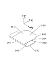
図5は固定板220の第三の実施形態の斜視図である。固定板220は平板状の形状であるが、広大面のうち図示していないインク袋収納ケースに接する広大なスライド面となるb21面260を正面にしたときT字型をしており、かつZ方向と直角の関係にある。またb21面260を正面にしたときに線対称軸と平行となる向きをX方向、線対称軸と直角となる向きをY方向とする。X方向のうち幅の狭い一端の2角にはXY平面上に面取りb265が施されている。固定板220のb21面260の裏側にはb21面260と平行となるb22面261があるが、b22面261はb21面260より面積が小さく線対称軸を含む単一の面より構成されている。さらにb22面261は図示していないインク袋と接する面となる。b22面261を除く残りの面積は両端にふたつのb27面266より構成されており、b27面266は面取りb265寄りの板厚が薄くなるようにb22面261に対して傾斜している。また側面のふたつのb24面263は固定板220のY方向の両端の面であり、その形状はb21面260とb27面266は平行でないため略台形となる。さらにふたつのb25面264はb22面261のY方向の両端の面である。
FIG. 5 is a perspective view of the third embodiment of the fixing
本実施形態ではスライド面となるb21面260とb22面261と、b24面263とb25面264が平行をなし、b21面260とb24面263が直角をなす関係にある。b26面265は固定板220が+X方向へ移動するときの案内として機能する。またb24面263を正面にしたときにb21面260に対してb27面266は平行でない角をなす傾斜面となっている。b27面266はb26面265と同様に案内を目的とした機能も実現できるが、b27面266と平行な角となる傾斜面の位置決め面またはひとつ以上の突起部と対向させることで+X方向とY方向の位置決めと固定を実現可能である。さらにb22面261とb27面266が同一面となってb21面260と平行でない角をなす傾斜面とし、+X方向とY方向の位置決めと固定を実現することも可能である。また本実形態のような固定板220は射出成形による製法が望ましい。また、本実施形態では、Y方向の幅が狭い部分すなわちb25面264の対で挟まれている部分と、幅の広い部分b24面263の対で挟まれている部分があり、その境界部分は固定板220を固定するための係合部に含まれている。
In the present embodiment, the
図6(a)は固定板の第四の実施形態の斜視図であり、図6(b)は第四の実施形態の固定板の別の角度から見た斜視図であり、図6(c)は第四の実施形態の固定板の側方から見た正面図である。固定板320は広大面のうち図示していないインク袋に接する一面となるb32面361に対してb33面362、b34面363が互いに直角をなす関係にある。しかし固定板320のb32面361の裏面は平面ではなく、複数の線状の突起部先端を結んだ仮想平面よりなるb31面360となっている。固定板320の位置決めと固定を実現する形状は平面以外の形状でも実現可能であり、所定の形状の突起部または複数の突起部先端を結んだ仮想線、仮想面、あるいは所定の形状の曲面部でも可能である。固定板320を射出成形によって製造する場合、大きな面積の平面を作成するのは難しいため、b31面360のように複数の線状の突起部先端を結んだ仮想平面とすることで、固定板320の歩留まりや製造コストの低減を実現できる。また、ケースとの接触抵抗を少なくでき、スライドが容易となる。
FIG. 6A is a perspective view of the fourth embodiment of the fixing plate, and FIG. 6B is a perspective view of the fixing plate of the fourth embodiment viewed from another angle, and FIG. ) Is a front view seen from the side of the fixing plate of the fourth embodiment. The fixing
図7は固定板の第五の実施形態の斜視図である。固定板420は平板状の形状であり、広大面のうち図示していないインク袋収納ケースに接する一面となるb41面460と、裏側の面となるもうひとつの広大面のb42面461に二つのスライド穴422が設けられている。二つのスライド穴422の壁面は長方形状となっており、4壁面より構成されている。図示していないインク袋の長手方向はX方向、短手方向はY方向、それぞれに直交する向きをZ方向とする。二つのスライド穴422の壁面のうちX方向に平行で固定板420の内側に位置する二つの面をb44面463とし、二つのスライド穴422の壁面のうちb44面463に直交し図示していないインク袋のインク供給口よりに位置するb43面462とする。b41面460に対向するインク袋収納ケースの位置決め面上にはスライド穴422の壁面であるb43面462、b44面463との対向面を設けた凸形状が備えられており、二組の対向面によって固定板420のインク袋収納ケースのX方向、Y方向の位置決めが可能となる。Z方向の位置決めはインク袋収納ケースを第1の実施形態と類似の形状にしても実現可能であるが、インク袋収納ケースからのフック状構造にスライド穴422を通して固定することによっても実現可能である。
FIG. 7 is a perspective view of a fifth embodiment of the fixing plate. The fixing
なお、図中では二つのスライド穴422は固定板420に対して対称形状、対称位置となっているが、固定板420の向きを管理するために非対称形状や非対称位置としてもよい。さらに複数種類のスライド穴422の形状と位置を設定して適合するインク袋収納ケースとの組合せを設けることにより、適切なインク袋とインク袋収納ケースの組合せに制限することができる。これによりインクジェットプリンターに適合しないインク袋の内容物を制限でき、機械的な誤挿入防止機能が実現できる。またスライド穴422の形状は長方形状以外の半円形状、三角形状などX方向、Y方向のいずれかまたは両方の位置決め可能な形状であればよい。
In the figure, the two
本実施形態の固定板420は射出成形の他に板状の樹脂または金属の抜き加工によって製造することが望ましい。
The fixing
10 インク袋
11 密閉袋
12 インク供給口
13 固定孔
14 検出板
20 固定板
30 インク袋収納ケース
31 バネ固定部
32 バネ
33 口固定部
50 a1面
51 a2面
52 a3面
53 a4面
60 b1面
61 b2面
62 b3面
63 b4面
110 インク袋
111 密閉袋
112 インク供給口
113 固定孔
114 検出板
120 固定板
121 腕部
130 インク袋収納ケース
131 バネ固定部
132 バネ
133 口固定部
150 a11面
151 a12面
152 a13面
153 a14面
154 a15面
160 b11面
161 b12面
162 b13面
163 b14面
164 b15面
220 固定板
260 b21面
261 b22面
262 b23面
263 b24面
264 b25面
265 b26面
266 b27面
320 固定板
360 b31面
361 b32面
362 b33面
363 b34面
420 固定板
422 位置決め穴
460 b41面
461 b42面
462 b43面
463 b44面
DESCRIPTION OF
Claims (13)
前記密閉袋の一方の面であって前記密閉袋の長手方向の中央を含む位置に固定され、外部に配置された位置決め面と対向することで位置決めするスライド面を有し、前記位置決め面と前記スライド面とを対向させることで少なくとも1方向の位置決めが可能な固定板を有することを特徴とするインク袋。 In an ink bag having a flexible sealed bag for storing ink, and an ink supply port for supplying ink to one end of the sealed bag,
One surface of the hermetic bag, which is fixed at a position including the center in the longitudinal direction of the hermetic bag, and has a slide surface for positioning by facing a positioning surface arranged outside, the positioning surface and the An ink bag comprising a fixed plate capable of positioning in at least one direction by facing a slide surface.
前記インク供給口を固定する口固定部と、
前記位置決め面と、
を有するインク袋格納ケース。 A flexible airtight bag for storing ink, an ink supply port for supplying ink to one end of the airtight bag, and one surface of the airtight bag, including the center in the longitudinal direction of the airtight bag A fixed plate that is fixed in position and has a slide surface that is positioned by facing a positioning surface that is arranged outside, and that can be positioned in at least one direction by facing the positioning surface and the slide surface; An ink bag storage case for storing an ink bag,
A port fixing part for fixing the ink supply port;
The positioning surface;
Ink bag storage case.
前記検出器から検出可能に前記検出板の位置検出部が露出する開口を有することを特徴とする請求項10または請求項11に記載のインク袋格納ケース。 The other surface of the hermetic bag is fixed at a position sandwiching the hermetic bag with respect to the fixing plate, and the position is detected by detecting with an external detector in conjunction with the deformation of the hermetic bag. Having a detection plate
The ink bag storage case according to claim 10 or 11, further comprising an opening through which a position detection unit of the detection plate is exposed so as to be detectable from the detector.
Priority Applications (1)
| Application Number | Priority Date | Filing Date | Title |
|---|---|---|---|
| JP2011048201A JP5736195B2 (en) | 2011-03-04 | 2011-03-04 | Ink bag, ink bag storage case, and ink cartridge |
Applications Claiming Priority (1)
| Application Number | Priority Date | Filing Date | Title |
|---|---|---|---|
| JP2011048201A JP5736195B2 (en) | 2011-03-04 | 2011-03-04 | Ink bag, ink bag storage case, and ink cartridge |
Publications (2)
| Publication Number | Publication Date |
|---|---|
| JP2012183714A true JP2012183714A (en) | 2012-09-27 |
| JP5736195B2 JP5736195B2 (en) | 2015-06-17 |
Family
ID=47014231
Family Applications (1)
| Application Number | Title | Priority Date | Filing Date |
|---|---|---|---|
| JP2011048201A Active JP5736195B2 (en) | 2011-03-04 | 2011-03-04 | Ink bag, ink bag storage case, and ink cartridge |
Country Status (1)
| Country | Link |
|---|---|
| JP (1) | JP5736195B2 (en) |
Cited By (8)
| Publication number | Priority date | Publication date | Assignee | Title |
|---|---|---|---|---|
| JP2014121870A (en) * | 2012-12-21 | 2014-07-03 | Jetbest Corp | Replaceable ink bag, and ink cartridge constituted with the same |
| JP2015139882A (en) * | 2014-01-27 | 2015-08-03 | セイコーエプソン株式会社 | Recorder |
| JP2016010910A (en) * | 2014-06-30 | 2016-01-21 | 京セラドキュメントソリューションズ株式会社 | Ink container and inkjet recording device comprising the same |
| JP2016010911A (en) * | 2014-06-30 | 2016-01-21 | 京セラドキュメントソリューションズ株式会社 | Ink container and inkjet recording device comprising the same |
| US9327507B2 (en) | 2013-02-20 | 2016-05-03 | Océ-Technologies B.V. | Liquid container |
| JP2018047707A (en) * | 2017-11-28 | 2018-03-29 | セイコーエプソン株式会社 | Recording device |
| WO2018084232A1 (en) * | 2016-11-04 | 2018-05-11 | エンジニアリングシステム株式会社 | Body movement suppression bag and method for adjusting pressing force using body movement suppression bag |
| JP2019069574A (en) * | 2017-10-11 | 2019-05-09 | 株式会社沖データ | Ink cartridge and inkjet printer |
Citations (2)
| Publication number | Priority date | Publication date | Assignee | Title |
|---|---|---|---|---|
| JP2004025900A (en) * | 1996-10-07 | 2004-01-29 | Seiko Epson Corp | Ink cartridge and its manufacturing method |
| JP2010149461A (en) * | 2008-12-26 | 2010-07-08 | Seiko I Infotech Inc | Ink container, manufacturing method of ink container, and ink supply method |
-
2011
- 2011-03-04 JP JP2011048201A patent/JP5736195B2/en active Active
Patent Citations (2)
| Publication number | Priority date | Publication date | Assignee | Title |
|---|---|---|---|---|
| JP2004025900A (en) * | 1996-10-07 | 2004-01-29 | Seiko Epson Corp | Ink cartridge and its manufacturing method |
| JP2010149461A (en) * | 2008-12-26 | 2010-07-08 | Seiko I Infotech Inc | Ink container, manufacturing method of ink container, and ink supply method |
Cited By (12)
| Publication number | Priority date | Publication date | Assignee | Title |
|---|---|---|---|---|
| JP2014121870A (en) * | 2012-12-21 | 2014-07-03 | Jetbest Corp | Replaceable ink bag, and ink cartridge constituted with the same |
| US9327507B2 (en) | 2013-02-20 | 2016-05-03 | Océ-Technologies B.V. | Liquid container |
| JP2015139882A (en) * | 2014-01-27 | 2015-08-03 | セイコーエプソン株式会社 | Recorder |
| CN107097527A (en) * | 2014-01-27 | 2017-08-29 | 精工爱普生株式会社 | Tape deck |
| CN107097527B (en) * | 2014-01-27 | 2019-02-15 | 精工爱普生株式会社 | Recording device |
| JP2016010910A (en) * | 2014-06-30 | 2016-01-21 | 京セラドキュメントソリューションズ株式会社 | Ink container and inkjet recording device comprising the same |
| JP2016010911A (en) * | 2014-06-30 | 2016-01-21 | 京セラドキュメントソリューションズ株式会社 | Ink container and inkjet recording device comprising the same |
| WO2018084232A1 (en) * | 2016-11-04 | 2018-05-11 | エンジニアリングシステム株式会社 | Body movement suppression bag and method for adjusting pressing force using body movement suppression bag |
| JPWO2018084232A1 (en) * | 2016-11-04 | 2019-09-26 | エンジニアリングシステム株式会社 | Body movement suppression bag and pressing force adjustment method using the body movement suppression bag |
| JP7132618B2 (en) | 2016-11-04 | 2022-09-07 | エンジニアリングシステム株式会社 | motion control bag |
| JP2019069574A (en) * | 2017-10-11 | 2019-05-09 | 株式会社沖データ | Ink cartridge and inkjet printer |
| JP2018047707A (en) * | 2017-11-28 | 2018-03-29 | セイコーエプソン株式会社 | Recording device |
Also Published As
| Publication number | Publication date |
|---|---|
| JP5736195B2 (en) | 2015-06-17 |
Similar Documents
| Publication | Publication Date | Title |
|---|---|---|
| JP5736195B2 (en) | Ink bag, ink bag storage case, and ink cartridge | |
| US10500866B2 (en) | Liquid container | |
| KR100416332B1 (en) | Ink cartridge and its construction method | |
| EP3628497B1 (en) | Ink cartridge | |
| US6416166B1 (en) | Ink cartridge with alignment features and method of inserting cartridge into a printer receptacle | |
| US20160263905A1 (en) | Tank, tank unit, liquid ejection system, and liquid ejection apparatus | |
| JPWO2006019034A1 (en) | Ink cartridge for ink jet recording apparatus | |
| JP2015527219A (en) | Fluid container with two sealing membranes for microfluidic applications | |
| US20170341395A1 (en) | Liquid ejecting apparatus | |
| JP2015196300A (en) | cartridge case | |
| EP2388144B1 (en) | Ink cartridge and printer | |
| JP2007230089A (en) | Liquid storing cartridge | |
| US20140071210A1 (en) | Liquid Container | |
| WO2011001723A1 (en) | Cassette tape | |
| US9254667B2 (en) | Recording apparatus | |
| US11370224B2 (en) | Liquid storage container | |
| JP4613616B2 (en) | Liquid container module and liquid ejecting apparatus | |
| JP4292832B2 (en) | Ink package | |
| JP3185521U (en) | ink cartridge | |
| US8807722B2 (en) | Ink cartridge and inkjet printer | |
| JP3979336B2 (en) | Liquid conducting material, method for manufacturing the same, and liquid ejecting apparatus | |
| JP2024035919A (en) | How to reuse liquid containers and adapters | |
| EP2311641A1 (en) | Ink cartridges | |
| JP2012210727A (en) | Ink cartridge | |
| JP2013252686A (en) | Ink tank |
Legal Events
| Date | Code | Title | Description |
|---|---|---|---|
| A621 | Written request for application examination |
Free format text: JAPANESE INTERMEDIATE CODE: A621 Effective date: 20140116 |
|
| A977 | Report on retrieval |
Free format text: JAPANESE INTERMEDIATE CODE: A971007 Effective date: 20140922 |
|
| A131 | Notification of reasons for refusal |
Free format text: JAPANESE INTERMEDIATE CODE: A131 Effective date: 20141014 |
|
| A521 | Request for written amendment filed |
Free format text: JAPANESE INTERMEDIATE CODE: A523 Effective date: 20141202 |
|
| TRDD | Decision of grant or rejection written | ||
| A01 | Written decision to grant a patent or to grant a registration (utility model) |
Free format text: JAPANESE INTERMEDIATE CODE: A01 Effective date: 20150407 |
|
| A61 | First payment of annual fees (during grant procedure) |
Free format text: JAPANESE INTERMEDIATE CODE: A61 Effective date: 20150420 |
|
| R150 | Certificate of patent or registration of utility model |
Ref document number: 5736195 Country of ref document: JP Free format text: JAPANESE INTERMEDIATE CODE: R150 |
|
| RD04 | Notification of resignation of power of attorney |
Free format text: JAPANESE INTERMEDIATE CODE: R3D04 |
|
| R250 | Receipt of annual fees |
Free format text: JAPANESE INTERMEDIATE CODE: R250 |
|
| S111 | Request for change of ownership or part of ownership |
Free format text: JAPANESE INTERMEDIATE CODE: R313111 |
|
| R350 | Written notification of registration of transfer |
Free format text: JAPANESE INTERMEDIATE CODE: R350 |
|
| S111 | Request for change of ownership or part of ownership |
Free format text: JAPANESE INTERMEDIATE CODE: R313111 |
|
| R350 | Written notification of registration of transfer |
Free format text: JAPANESE INTERMEDIATE CODE: R350 |