JP2012183339A - Rotary reel unit of game machine - Google Patents
Rotary reel unit of game machine Download PDFInfo
- Publication number
- JP2012183339A JP2012183339A JP2012120672A JP2012120672A JP2012183339A JP 2012183339 A JP2012183339 A JP 2012183339A JP 2012120672 A JP2012120672 A JP 2012120672A JP 2012120672 A JP2012120672 A JP 2012120672A JP 2012183339 A JP2012183339 A JP 2012183339A
- Authority
- JP
- Japan
- Prior art keywords
- reel
- symbols
- symbol
- reel unit
- specific
- Prior art date
- Legal status (The legal status is an assumption and is not a legal conclusion. Google has not performed a legal analysis and makes no representation as to the accuracy of the status listed.)
- Granted
Links
Images


Abstract
Description
本発明はスロットマシンや弾球遊技機といった遊技機に用いられる回転リールユニットに関するものである。 The present invention relates to a rotary reel unit used in a gaming machine such as a slot machine or a ball game machine.
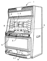
従来、この種の遊技機の回転リールユニットとしては、例えば、図4に示すスロットマシン1に用いられている図5(a)に示す回転リールユニット11がある。
Conventionally, as a rotary reel unit of this type of gaming machine, for example, there is a rotary reel unit 11 shown in FIG. 5A used in the
回転リールユニット11はリールドラム12の外周にリール帯3が張り付けられて構成されている。このリール帯13の周囲には図示しない種々の図柄(シンボル)が描かれている。これらシンボルは、各リールドラム12の内部に設けられた図5(b)に示すバックランプ14によって背後から映し出され、スロットマシン1の各窓2から観察される。バックランプ14はリールドラム12の内部に固定される基板18に3個取り付けられている。投入口3にメダルが投入されてスタートレバー4が操作されると、ブラケット15に取り付けられたモータ16が駆動され、各リールドラム12が回転する。従って、各窓2には高速に移動するシンボルが観察される。
The rotary reel unit 11 is configured by attaching a
遊技者によってストップスイッチ5が押圧操作されると各リールドラム12は停止制御される。この停止制御は、ホトセンサによって遮蔽板17の通過が検出されることにより行われ、また、遊技者による各ストップスイッチ5の操作タイミングに応じて行われる。従って、遊技者は高速に移動する特定のシンボルの通過を目印にストップスイッチ5を操作し、各リールドラム12の停止時に所定のシンボル組合せがペイライン6上に停止表示されるのを狙う。ペイライン6上に所定のシンボル組合せが停止表示されると入賞が生じ、払出口7から所定枚数のメダルが受け皿8に払い出される。
When the player presses the
このようなストップスイッチ5の操作タイミングは熟練者でないと判別がつかず、初心者は高速で回転する各シンボルの相違を識別することが困難である。従って、従来、ストップスイッ5の操作タイミングを初心者に教える様々な手段が提案されている。
Such an operation timing of the
例えば、下記の特許文献1には、リール帯の特定シンボルに近接する位置に孔を開け、この孔から漏れる内部ランプの光によってストップスイッチの操作タイミングを遊技者に報知する手段が開示されている。
For example, the following
また、下記の特許文献2には、リール帯の特定シンボルが描かれた帯領域に光透過性を持たせ、特定シンボルが窓に出現すると内部ランプの光によってその特定シンボルを目立たせる手段が開示されている。遊技者は目立たせられたこの特定シンボルの出現によってストップスイッチの操作タイミングを掴むことが出来る。
Further,
また、下記の特許文献3には、リール帯の特定シンボルを蛍光物質で描き、この特定シンボルに光を照射してその特定シンボルを目立たせる手段が開示されている。このような特定シンボルの出現によってもストップスイッチの操作タイミングを掴むことが出来る。
しかしながら、上記従来のいずれの遊技機の回転リールユニットにおいても、内部光や蛍光物質によって識別させることの出来る特定シンボルは1種類である。従って、上記従来のいずれの遊技機の回転リールユニットによっても、リール帯の円周方向に描かれた複数種類の特定シンボルの通過を遊技者に識別させることは出来なかった。 However, in any of the conventional rotating reel units of the above gaming machines, there is only one specific symbol that can be identified by internal light or a fluorescent material. Therefore, it has been impossible for the player to identify the passage of a plurality of types of specific symbols drawn in the circumferential direction of the reel band by any of the conventional rotating reel units of the gaming machines.
遊技機の入賞態様には様々な態様があり、特定シンボルを含むシンボル組合せによって生じる入賞態様と、異なる種類の特定シンボルを含むシンボル組合せによって生じる入賞態様とでは、遊技内容や、それに伴う価値付与も異なる。遊技者の好む入賞態様も人様々であり、停止表示させたい特定シンボルの種類も遊技者によって異なる。従来の遊技機の回転リールユニットでは、表示窓を通過するこのような異種の特定シンボルを初心者に識別させることは上記のように出来なかった。このため、遊技機の持つ興趣を初心者は従来十分に味わうことが出来なかった。 There are a variety of winning modes for gaming machines, and in the winning mode generated by a symbol combination including a specific symbol and the winning mode generated by a symbol combination including a different type of specific symbol, the contents of the game and the associated value addition are also included. Different. The winning mode preferred by the player varies from person to person, and the type of the specific symbol desired to be stopped and displayed varies depending on the player. In conventional rotary reel units of gaming machines, it has not been possible for beginners to identify such different kinds of specific symbols passing through the display window. For this reason, beginners have not been able to fully enjoy the fun of gaming machines.
本発明はこのような課題を解決するためになされたもので、上下方向に回転可能な円筒状をしたリールドラムと、このリールドラムの外周に設けられる、形状が異なる2種類の特定図柄と他の種々の図柄が描かれた3つのリール帯と、これら図柄を背後から照らす光源とを備えて構成される遊技機の回転リールユニットにおいて、
半透明部分が前記2種類の特定図柄のそれぞれの所定の図柄部分の周囲に形成されるとともに、前記2種類の特定図柄のうち一方の特定図柄では右方に、他方の特定図柄では左方に位置することを特徴とするものである。
The present invention has been made in order to solve such problems. A cylindrical reel drum that can be rotated in the vertical direction, two types of specific symbols provided on the outer periphery of the reel drum, and other different shapes. In a rotary reel unit of a gaming machine configured to include three reel strips on which various symbols are drawn and a light source that illuminates these symbols from behind,
A semi-transparent portion is formed around each of the predetermined symbol portions of the two types of specific symbols, and one of the two types of specific symbols is on the right side and the other specific symbol is on the left side. It is characterized by being located.
本構成においては、リールドラムが回転すると、形状が異なる2種類の特定図柄は、前記リールドラムの回転方向に直交する方向において、前記2種類の特定図柄のうち一方の特定図柄では右方に、他方の特定図柄では左方の位置で、発光する。従って、遊技者は発光位置の相違から特定図柄の種類を識別することが出来る。 In this configuration, when the reel drum rotates, the two types of specific symbols having different shapes are in the right direction in one of the two specific symbols in the direction orthogonal to the rotation direction of the reel drum, The other specific symbol emits light at the left position. Therefore, the player can identify the type of the specific symbol from the difference in the light emission position.
このため、このような本発明によれば、初心者であっても容易に高速に移動する特定図柄の識別を行うことが可能となり、初心者であっても遊技機の持つ興趣を十分堪能することが可能となる。 Therefore, according to the present invention as described above, even a beginner can easily identify a specific symbol that moves at high speed, and even a beginner can fully enjoy the interest of a gaming machine. It becomes possible.
次に、本発明による遊技機の回転リールユニットを前述したスロットマシンに適用した一実施形態について説明する。 Next, an embodiment in which the rotary reel unit of the gaming machine according to the present invention is applied to the slot machine described above will be described.
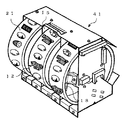
図3は本実施形態による回転リールユニット41の斜視図であり、図1(a)はこの回転リールユニット41に用いられているリール帯21の平面図である。本実施形態による回転リールユニット41は、このリール帯21以外の構成は図5に示す回転リールユニット11の構成と同じであり、図3において図5と同一または相当する部分には同一符号を付している。 FIG. 3 is a perspective view of the rotary reel unit 41 according to the present embodiment, and FIG. 1A is a plan view of the reel band 21 used in the rotary reel unit 41. The configuration of the rotary reel unit 41 according to the present embodiment is the same as the configuration of the rotary reel unit 11 shown in FIG. 5 except for the reel band 21, and the same or corresponding parts in FIG. doing.
リール帯21は円筒状をしたリールドラム12の外周に沿って曲げられ、その外周面に貼られている。リール帯21の表面には種々のシンボルが描かれており、本実施形態ではそのうちのセブン22およびウルフ23を特定シンボルとしている。すなわち、本実施形態ではこれらセブン22およびウルフ23の異種シンボルの識別を容易化する。 The reel band 21 is bent along the outer periphery of the cylindrical reel drum 12, and is attached to the outer peripheral surface. Various symbols are drawn on the surface of the reel band 21, and in the present embodiment, the seven 22 and the wolf 23 are specified symbols. That is, in the present embodiment, the different symbols of the seven 22 and the wolf 23 can be easily identified.
リール帯21は透明フィルム材からなり、各シンボルはこの透明フィルム材の裏面に光透過性有色インキで印刷されて描かれている。この際、リール帯21上の各セブン22の図柄部分はそれぞれ光透過性赤色インキで着色され、各ウルフ23の図柄部分はそれぞれ光透過性青色インキで着色されている。リール帯21はこの光透過性有色インキによる各シンボルの印刷後、光透過性白色インキで背景が印刷される。最後に、セブン22およびウルフ23の図柄領域を除き、遮光性銀色インキが印刷されてマスク処理が施されている。 The reel band 21 is made of a transparent film material, and each symbol is drawn on the back surface of the transparent film material by printing with light transmissive colored ink. At this time, the design portion of each seven 22 on the reel band 21 is colored with a light transmissive red ink, and the design portion of each wolf 23 is colored with a light transmissive blue ink. The reel band 21 is printed with a background of light-transmitting white ink after each symbol is printed with the light-transmitting colored ink. Finally, except for the design area of the seven 22 and the wolf 23, a light-shielding silver ink is printed and masked.
このような過程を経て、図1(a)に示すリール帯21が得られている。すなわちリール帯21は、セブン22およびウルフ23の異なる2つの特定シンボルの図柄部分だけが、それぞれ半透明に形成され、かつ、それぞれ異なる色に着色されている。なお、セブン22の図柄領域に付された格子は赤色を表し、ウルフ23の図柄領域に付された斜線は青色を表している。また、光透過性白色インキによる背景印刷をセブン22,ウルフ23の特定図柄領域を除く領域に対して行い、セブン22,ウルフ23の特定図柄領域を半透明ではなく、透明に形成しても良い。 Through such a process, the reel band 21 shown in FIG. 1A is obtained. That is, in the reel band 21, only the symbol portions of two different specific symbols of the seven 22 and the wolf 23 are respectively formed translucent and colored in different colors. The grid attached to the symbol area of the seven 22 represents red, and the diagonal line attached to the symbol area of the wolf 23 represents blue. Further, background printing with light-transmitting white ink may be performed on the areas excluding the specific design areas of the seven 22 and wolf 23 so that the specific design areas of the seven 22 and wolf 23 are not translucent but transparent. .
このような構成において、モータ16が駆動されてリールドラム12が回転すると、リールドラム12の外周に貼られたリール帯21も回転する。リールドラム12の内部に設けられた基板18に取り付けられたバックランプ14は、常時点灯している。このため、リール帯21が回転してセブン22のシンボルがバックランプ14の照射部前部を通過すると、セブン22はバックランプ14の出射光を背後に浴びて赤色に発光する。また、ウルフ23のシンボルがバックランプ14の照射部前部を通過すると、ウルフ23はバックランプ14の出射光を背後に浴びて青色に発光する。 In such a configuration, when the motor 16 is driven and the reel drum 12 rotates, the reel band 21 attached to the outer periphery of the reel drum 12 also rotates. The back lamp 14 attached to the substrate 18 provided inside the reel drum 12 is always lit. For this reason, when the reel band 21 rotates and the symbol of the seven 22 passes the front part of the irradiation part of the back lamp 14, the seven 22 emits light emitted from the back lamp 14 behind and emits red light. Further, when the symbol of the wolf 23 passes through the front part of the irradiating part of the back lamp 14, the wolf 23 emits light emitted from the back lamp 14 in the background and emits blue light.
これらセブン22の赤色発光やウルフ23の青色発光はスロットマシン1の窓2から観察される。従って、窓2から観察される赤色の発光により、セブン22のシンボルが窓2を通過するタイミングを判別することが出来、また、窓2から観察される青色の発光により、ウルフ23のシンボルが窓2を通過するタイミングを判別することが出来る。
The red light emission of the seven 22 and the blue light emission of the wolf 23 are observed from the
よって、遊技者はこの発光色の相違から特定シンボルの種類を識別することが出来、所望の特定シンボルがペイライン6上に停止表示されるのを狙ってストップスイッチ5を操作することが可能となる。この結果、初心者であっても、ペイライン6上にセブン22のシンボルを並べたり、ウルフ23のシンボルを並べることが容易に行える。
Therefore, the player can identify the type of the specific symbol from the difference in the emission color, and can operate the
図1(b)は他の実施形態による回転リールユニットに用いられるリール帯31の平面図である。本実施形態によるその他の構成は上記実施形態の構成と同じである。 FIG. 1B is a plan view of a reel band 31 used in a rotary reel unit according to another embodiment. Other configurations according to the present embodiment are the same as those of the above-described embodiment.
本実施形態のリール帯31では、セブン32およびウルフ33の2つの各特定シンボルの図柄の一部分に、それぞれ円形の半透明部分32aおよび33aが形成されている。つまり、セブン32のシンボルでは、図2(a)の拡大図に示すように、ウルフの足跡部分に円形半透明部分32aが形成されている。また、ウルフ33のシンボルでは、図2(b)の拡大図に示すように、目の部分に円形半透明部分33aが形成されている。
In the reel band 31 of the present embodiment, circular translucent portions 32a and 33a are respectively formed in a part of the symbols of the two specific symbols of the seven 32 and the wolf 33. That is, in the symbol of
各シンボルは上記実施形態と同様にリール帯31を形成する透明フィルム材の裏面に光透過性有色インキが印刷されて描かれているが、各半透明部分32aおよび33aにはこの有色インキが印刷されていない。その後の光透過性白色インキによる背景印刷は全面に対して行われ、最後の遮光性銀色インキによるマスク処理は各半透明部分32aおよび33aを除く領域に対して行われている。 Each symbol is drawn with light-transmitting colored ink printed on the back surface of the transparent film material forming the reel band 31 as in the above embodiment, but this colored ink is printed on each translucent portion 32a and 33a. It has not been. Subsequent background printing with the light-transmitting white ink is performed on the entire surface, and the final masking process with the light-shielding silver ink is performed on the areas except the translucent portions 32a and 33a.
なお、光透過性白色インキによる背景印刷を各部分32a,33aを除く領域に対して行い、各部分32a,33aを半透明ではなく、透明に形成しても良い。 The background printing with the light-transmitting white ink may be performed on the region excluding the portions 32a and 33a, and the portions 32a and 33a may be formed not transparent but transparent.
セブン32のシンボルに形成された半透明部分32aと、ウルフ33のシンボルに形成された半透明部分33aとは、リールドラム12の回転方向に直交する方向、つまりリール帯31の幅方向において異なる位置に配されている。すなわち、セブン32のシンボルではこの幅方向の右方に半透明部分32aが位置しており、ウルフ33のシンボルではこの幅方向の左方に半透明部分33aが位置している。
The translucent part 32a formed on the symbol of the seven 32 and the translucent part 33a formed on the symbol of the wolf 33 are different in the direction orthogonal to the rotation direction of the reel drum 12, that is, in the width direction of the reel band 31. It is arranged in. That is, the semi-transparent portion 32a is located on the right in the width direction in the
このような本実施形態において、リールドラム12が回転するとリールドラム12の外周に貼られたリール帯31が回転し、各半透明部分32a,33aも回転する。本実施形態においても、リールドラム12の内部に設けられたバックランプ14は常時点灯しているため、リール帯31が回転して各半透明部分32a,33aがバックランプ14の照射部前部を通過すると、各半透明部分32a,33aからバックランプ14の出射光が漏れ、各半透明部分32a,33aは発光する。 In this embodiment, when the reel drum 12 rotates, the reel band 31 attached to the outer periphery of the reel drum 12 rotates, and the translucent portions 32a and 33a also rotate. Also in the present embodiment, since the back lamp 14 provided inside the reel drum 12 is always lit, the reel band 31 rotates and the translucent portions 32a and 33a cover the front part of the irradiation part of the back lamp 14. If it passes, the emitted light of the back lamp 14 leaks from each translucent part 32a, 33a, and each translucent part 32a, 33a emits light.
これら各半透明部分32a,33aの発光はスロットマシン1の窓2から観察される。この際、セブン32のシンボルに形成された半透明部分32aはリール帯31の幅方向の右側に観察され、ウルフ33のシンボルに形成された半透明部分33aはリール帯31の幅方向の左側に観察される。
The light emission of these translucent portions 32 a and 33 a is observed from the
すなわち、窓2の右方に観察される半透明部分32aの発光により、セブン32のシンボルが窓2を通過するタイミングを判別することが出来、また、窓2の左方に観察される半透明部分33aの発光により、ウルフ33のシンボルが窓2を通過するタイミングを判別することが出来る。
That is, it is possible to determine the timing at which the symbol of the seven 32 passes through the
よって、遊技者はこの発光位置の相違から特定シンボルの種類を識別することが出来、所望の特定シンボルがペイライン6上に停止表示されるのを狙ってストップスイッチ5を操作することが可能となる。この結果、本実施形態による回転リールユニットにおいても、初心者であっても、ペイライン6上にセブン32のシンボルを並べたり、ウルフ33のシンボルを並べることが容易に行える。
Therefore, the player can identify the type of the specific symbol based on the difference in the light emission position, and can operate the
なお、上記実施形態では本発明をスロットマシンの回転リールユニットに適用した場合について説明したが、パチンコ機やピンボールゲーム機,スマートボールゲーム機といった弾球遊技機の回転リールユニットに適用することも可能であり、上記実施形態と同様な効果が奏される。 In the above embodiment, the case where the present invention is applied to a rotating reel unit of a slot machine has been described. However, the present invention may be applied to a rotating reel unit of a ball game machine such as a pachinko machine, a pinball game machine, or a smart ball game machine. It is possible, and the same effect as the above-mentioned embodiment is produced.
21,31…リール帯、22,32…セブン(特定図柄)、23,33…ウルフ(特定図柄)、32a,33a…半透明部分。 21, 31... Reel band, 22, 32... Seven (specific symbol), 23, 33... Wolf (specific symbol), 32 a, 33 a.
Claims (3)
半透明部分が前記2種類の特定図柄のそれぞれの所定の図柄部分の周囲に形成されるとともに、前記2種類の特定図柄のうち一方の特定図柄では右方に、他方の特定図柄では左方に位置することを特徴とする遊技機の回転リールユニット。 A cylindrical reel drum that can rotate in the vertical direction, three reel bands on the outer periphery of the reel drum that have two different specific shapes and other various symbols drawn on them, and In a rotating reel unit of a gaming machine configured with a light source that illuminates from behind,
A semi-transparent portion is formed around each of the predetermined symbol portions of the two types of specific symbols, and one of the two types of specific symbols is on the right side and the other specific symbol is on the left side. A rotary reel unit of a gaming machine characterized by being positioned.
Priority Applications (1)
| Application Number | Priority Date | Filing Date | Title |
|---|---|---|---|
| JP2012120672A JP5126441B2 (en) | 2012-05-28 | 2012-05-28 | Rotating reel unit for gaming machines |
Applications Claiming Priority (1)
| Application Number | Priority Date | Filing Date | Title |
|---|---|---|---|
| JP2012120672A JP5126441B2 (en) | 2012-05-28 | 2012-05-28 | Rotating reel unit for gaming machines |
Related Parent Applications (1)
| Application Number | Title | Priority Date | Filing Date |
|---|---|---|---|
| JP2011251643A Division JP5126404B2 (en) | 2011-11-17 | 2011-11-17 | Rotating reel unit for gaming machines |
Publications (2)
| Publication Number | Publication Date |
|---|---|
| JP2012183339A true JP2012183339A (en) | 2012-09-27 |
| JP5126441B2 JP5126441B2 (en) | 2013-01-23 |
Family
ID=47013966
Family Applications (1)
| Application Number | Title | Priority Date | Filing Date |
|---|---|---|---|
| JP2012120672A Expired - Lifetime JP5126441B2 (en) | 2012-05-28 | 2012-05-28 | Rotating reel unit for gaming machines |
Country Status (1)
| Country | Link |
|---|---|
| JP (1) | JP5126441B2 (en) |
Cited By (1)
| Publication number | Priority date | Publication date | Assignee | Title |
|---|---|---|---|---|
| JP2018102381A (en) * | 2016-12-22 | 2018-07-05 | 京楽産業.株式会社 | Game machine |
Families Citing this family (1)
| Publication number | Priority date | Publication date | Assignee | Title |
|---|---|---|---|---|
| JP5126441B2 (en) | 2012-05-28 | 2013-01-23 | 株式会社ユニバーサルエンターテインメント | Rotating reel unit for gaming machines |
Citations (16)
| Publication number | Priority date | Publication date | Assignee | Title |
|---|---|---|---|---|
| JPS6268034A (en) * | 1985-09-19 | 1987-03-27 | Canon Inc | Structure for mounting motor |
| JPS6284485U (en) * | 1985-11-14 | 1987-05-29 | ||
| JPS6426925A (en) * | 1987-07-23 | 1989-01-30 | Nec Corp | Fault informing system for printer terminal |
| JPH0443358A (en) * | 1990-06-11 | 1992-02-13 | Fujitsu Ltd | Method for forming chip position identifying pattern |
| JPH04108468A (en) * | 1990-08-28 | 1992-04-09 | K R Tokkyo Kanri Kk | Illuminator for slot machine |
| JPH0581290A (en) * | 1991-09-21 | 1993-04-02 | Matsushita Electric Ind Co Ltd | Market display device |
| JPH0698964A (en) | 1992-09-22 | 1994-04-12 | Yamasa Kk | Slot machine |
| JPH06269535A (en) | 1993-03-18 | 1994-09-27 | Sigma Corp | Game device and rotor structure |
| JPH06327807A (en) | 1993-05-20 | 1994-11-29 | Eagle:Kk | Roulette game machine |
| JPH07100241A (en) * | 1993-10-06 | 1995-04-18 | Olympia:Kk | Slot machine |
| JPH07141472A (en) * | 1993-11-19 | 1995-06-02 | Sanyo Electric Co Ltd | Character string recognizing device |
| JPH0756726B2 (en) * | 1985-08-20 | 1995-06-14 | 松下電器産業株式会社 | Rotation synchronization mark detector |
| JPH08178198A (en) * | 1994-12-28 | 1996-07-12 | Tokyo Gas Co Ltd | Wide area monitoring device |
| JP3537630B2 (en) | 1997-04-18 | 2004-06-14 | アルゼ株式会社 | Gaming machine spinning reel unit |
| JP4352151B2 (en) | 2004-04-14 | 2009-10-28 | アルゼ株式会社 | Rotating reel unit for gaming machines |
| JP5126441B2 (en) | 2012-05-28 | 2013-01-23 | 株式会社ユニバーサルエンターテインメント | Rotating reel unit for gaming machines |
-
2012
- 2012-05-28 JP JP2012120672A patent/JP5126441B2/en not_active Expired - Lifetime
Patent Citations (16)
| Publication number | Priority date | Publication date | Assignee | Title |
|---|---|---|---|---|
| JPH0756726B2 (en) * | 1985-08-20 | 1995-06-14 | 松下電器産業株式会社 | Rotation synchronization mark detector |
| JPS6268034A (en) * | 1985-09-19 | 1987-03-27 | Canon Inc | Structure for mounting motor |
| JPS6284485U (en) * | 1985-11-14 | 1987-05-29 | ||
| JPS6426925A (en) * | 1987-07-23 | 1989-01-30 | Nec Corp | Fault informing system for printer terminal |
| JPH0443358A (en) * | 1990-06-11 | 1992-02-13 | Fujitsu Ltd | Method for forming chip position identifying pattern |
| JPH04108468A (en) * | 1990-08-28 | 1992-04-09 | K R Tokkyo Kanri Kk | Illuminator for slot machine |
| JPH0581290A (en) * | 1991-09-21 | 1993-04-02 | Matsushita Electric Ind Co Ltd | Market display device |
| JPH0698964A (en) | 1992-09-22 | 1994-04-12 | Yamasa Kk | Slot machine |
| JPH06269535A (en) | 1993-03-18 | 1994-09-27 | Sigma Corp | Game device and rotor structure |
| JPH06327807A (en) | 1993-05-20 | 1994-11-29 | Eagle:Kk | Roulette game machine |
| JPH07100241A (en) * | 1993-10-06 | 1995-04-18 | Olympia:Kk | Slot machine |
| JPH07141472A (en) * | 1993-11-19 | 1995-06-02 | Sanyo Electric Co Ltd | Character string recognizing device |
| JPH08178198A (en) * | 1994-12-28 | 1996-07-12 | Tokyo Gas Co Ltd | Wide area monitoring device |
| JP3537630B2 (en) | 1997-04-18 | 2004-06-14 | アルゼ株式会社 | Gaming machine spinning reel unit |
| JP4352151B2 (en) | 2004-04-14 | 2009-10-28 | アルゼ株式会社 | Rotating reel unit for gaming machines |
| JP5126441B2 (en) | 2012-05-28 | 2013-01-23 | 株式会社ユニバーサルエンターテインメント | Rotating reel unit for gaming machines |
Non-Patent Citations (16)
| Title |
|---|
| JPN3005000003; '「クランキーコンドル」' 必勝パチスロファン平成7年10月号 , 19951001, p.6-7, 株式会社日本文芸社 * |
| JPN3013000966; 必勝パチスロファン10月号 通巻39号, 19951001, PAGES 6-7, (株)日本文芸社 |
| JPN3013000967; ニューパルサー必勝ガイド:パチスロ必勝ガイド6月号増刊 VOL. 6, NO. 9 通巻70号, 199505, PAGES 132-133, (株)白夜書房 |
| JPN3013000968; パチンコ攻略マガジン1月号 VOL. 6, NO. 1 通巻57号, 19961201, PAGE 3 |
| JPN3013000969; パチスロ必勝ガイド2 VOL. 7, NO. 3 通巻80号, 19960201, PAGES 4-5 |
| JPN3013000970; パチスロ必勝ガイド5 , 199605, PAGES 58-61, (株)白夜書房 |
| JPN3013000971; パチスロ必勝ガイド9 VOL. 7, NO. 12 通巻89号, 19960901, PAGES 3-5 |
| JPN3013000972; 'パチスロ入門 勝利への扉' 必勝パチスロファン:パチンコファン増刊 VOL. 22, 19940430, PAGES 75-79, (株)日本文芸社 |
| JPN3013000973; 無効2004-80262号審決(平成18年3月7日) |
| JPN3013000974; 無効2004-80262号審決(平成19年11月27日) |
| JPN3013000975; 平成20年(行ケ)第10004号 審決取消請求事件 判決 |
| JPN3013000976; 訂正2008-390024号特許審決公報 , 20090327, 特許庁 |
| JPN3013000977; 平成20年(行ケ)第10254号 審決取消請求事件(特許) 判決 |
| JPN3013000978; 無効2011-800104号 審決 (平成24年3月27日) |
| JPN3013000979; 平成24年(行ケ)第10159号 審決取消請求事件 判決 |
| JPN4007003638; '「ニューパルサー」' パチスロ攻略マガジン1993年9月号 , 19930901, p.14-15, 株式会社双葉社 * |
Cited By (1)
| Publication number | Priority date | Publication date | Assignee | Title |
|---|---|---|---|---|
| JP2018102381A (en) * | 2016-12-22 | 2018-07-05 | 京楽産業.株式会社 | Game machine |
Also Published As
| Publication number | Publication date |
|---|---|
| JP5126441B2 (en) | 2013-01-23 |
Similar Documents
| Publication | Publication Date | Title |
|---|---|---|
| JP3537630B2 (en) | Gaming machine spinning reel unit | |
| JP5008685B2 (en) | Light emitting display device for game machine and game machine | |
| JP2001353346A (en) | Game machine | |
| JP2011062387A (en) | Game machine | |
| JP2007061465A (en) | Rotary drum type game machine | |
| JP4352151B2 (en) | Rotating reel unit for gaming machines | |
| JP5126441B2 (en) | Rotating reel unit for gaming machines | |
| JP4717938B2 (en) | Rotating reel unit for gaming machines | |
| JP4409149B2 (en) | Slot machine | |
| JP5126404B2 (en) | Rotating reel unit for gaming machines | |
| JP4817400B2 (en) | Reel belt manufacturing method for gaming machine | |
| JP5034083B2 (en) | Reel belt manufacturing method for gaming machine | |
| JP4193022B2 (en) | Game machine | |
| JP2003175164A (en) | Game machine | |
| JP2007111212A (en) | Game machine | |
| JP2009195751A (en) | Rotary reel unit of game machine | |
| JP5990728B2 (en) | Game machine | |
| JP2010172711A (en) | Method for manufacturing reel band for game machine | |
| JP2007319355A (en) | Slot machine | |
| JP2004105761A (en) | Rotating reel unit of game machine | |
| JP2004202275A (en) | Manufacturing method for rotary reel unit of game machine | |
| JP2004237116A (en) | Game machine | |
| JP2004209287A (en) | Game machine | |
| JP2004216178A (en) | Game machine | |
| JP2004209288A (en) | Method of manufacturing rotary reel unit of game machine |
Legal Events
| Date | Code | Title | Description |
|---|---|---|---|
| TRDD | Decision of grant or rejection written | ||
| A01 | Written decision to grant a patent or to grant a registration (utility model) |
Free format text: JAPANESE INTERMEDIATE CODE: A01 Effective date: 20121002 |
|
| A01 | Written decision to grant a patent or to grant a registration (utility model) |
Free format text: JAPANESE INTERMEDIATE CODE: A01 |
|
| A61 | First payment of annual fees (during grant procedure) |
Free format text: JAPANESE INTERMEDIATE CODE: A61 Effective date: 20121015 |
|
| R150 | Certificate of patent or registration of utility model |
Free format text: JAPANESE INTERMEDIATE CODE: R150 |
|
| FPAY | Renewal fee payment (event date is renewal date of database) |
Free format text: PAYMENT UNTIL: 20151109 Year of fee payment: 3 |
|
| R250 | Receipt of annual fees |
Free format text: JAPANESE INTERMEDIATE CODE: R250 |
|
| R250 | Receipt of annual fees |
Free format text: JAPANESE INTERMEDIATE CODE: R250 |
|
| EXPY | Cancellation because of completion of term |