JP4409149B2 - Slot machine - Google Patents
Slot machine Download PDFInfo
- Publication number
- JP4409149B2 JP4409149B2 JP2002148737A JP2002148737A JP4409149B2 JP 4409149 B2 JP4409149 B2 JP 4409149B2 JP 2002148737 A JP2002148737 A JP 2002148737A JP 2002148737 A JP2002148737 A JP 2002148737A JP 4409149 B2 JP4409149 B2 JP 4409149B2
- Authority
- JP
- Japan
- Prior art keywords
- reel
- light
- symbol
- light source
- reflector
- Prior art date
- Legal status (The legal status is an assumption and is not a legal conclusion. Google has not performed a legal analysis and makes no representation as to the accuracy of the status listed.)
- Expired - Fee Related
Links
Images


Description
【0001】
【発明の属する技術分野】
本発明は、複数種類の図柄が周面の周方向に沿って適宜配置されたリールを回転・停止させ、特定の組み合わせ図柄が有効ライン上に揃えば、所定の入賞が成立するスロットマシンに関する。
【0002】
【従来の技術】
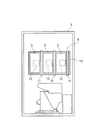
従来より、スロットマシンは、図1に示す如く、筐体1の前面に設けられた正面パネル2に、縦長のリール表示窓4が三つ横並びした図柄表示部3を形成すると共に、筐体1内に、各リール表示窓4の形成位置に対応させてリール5を三つ配置した構成が一般的となっている。
【0003】
各リール5の周面には、文字、数字、図形、キャラクターなどの複数種類の図柄(図示しない)を表示したリールテープが貼着されており、リール5,…の回転中は、それぞれの周面に表示された図柄がリール表示窓4内に次々に現れる一方、リール5,…を停止させた時は、各リール5の例えば三コマ分の図柄が、図柄表示部3に設定された上、中、下、右上がり及び右下がりの五本の停止ラインL,…上に整列した状態で表示される。
【0004】
停止ラインLは、メダル投入口6から投入されたメダルの投入枚数に応じて順次に有効化されて有効ラインとなる。例えば一枚のメダルが投入された時は、中央の横一本の停止ラインLが有効となり、二枚のメダルが投入された時は、上、中、下の横三本の停止ラインL,…が有効となり、三枚のメダルが投入された時は、五本全ての停止ラインL,…が有効となる。
【0005】
そして、正面パネル2の下方の張り出し面に設けられたスタートレバー7を操作して、三つのリール5,…を回転始動させた後、各リール5に対応して設けられたストップボタン8を押釦操作すれば、三つのリール5,…が順次停止するようになっている。この時、メダルの投入枚数により有効となった停止ラインL,…上に特定の組み合わせ図柄が揃えば、その組み合わせ図柄に応じた入賞が成立し、その入賞に応じて定められた所定枚数のメダルが払い出される。
【0006】
スロットマシンは、スタートレバー7を操作する度に制御部の乱数発生器で抽選を行い、その抽選結果に応じて有効ライン上に並ばせる図柄の組み合わせを決定するという完全確率方式を採用している。そして、抽選処理において入賞に当選すると、その入賞の種類に応じた個別のフラグが付与される(いわゆる「フラグが立つ」と呼ばれるもの)。
【0007】
実際には、フラグが立っていないと、ストップボタン8,…を押すタイミングが正しくても、特定の組み合わせ図柄を揃えることはできない。逆に言えば、フラグが立っている(ことがわかる)と、ストップボタン8,…を押すタイミングさえ正しければ、特定の組み合わせ図柄を揃えることは可能となる。従って、停止させたい図柄が所望位置に停止するようにストップボタン8,…を押す技術(いわゆる「目押し」)が重要となってくる。
【0008】
ところが、ストップボタン8,…を押すタイミングは、熟練者でないと判別がつかず、高速で回転するリールの各図柄を識別することが困難な初心者は、目的とする図柄を正確に狙うことができない。そこで、目押しを容易にするための手段として、一の図柄を光透過性としたり、あるいは一の図柄の近傍位置に光透過部を設け、リールの内側に配置される光源体の透過光を目印とするもの(特開平6−327808号、特開平7−100241号)や、種類の異なる二の図柄にそれぞれ異なる色に着色された光透過部を設け、リールの内側に配置される光源体のそれぞれ着色透過光を目印とするもの(特開平10−290856号)が提案されている。
【0009】
【発明が解決しようとする課題】
しかしながら、上記前者の手段の場合、透過光は一色に限定されるため、一種類の図柄に対してのみしか適用することができず、複数種類の図柄をぞれぞれ識別することはできない。従って、ビックボーナス入賞、レギュラーボーナス入賞あるいは小役入賞等の複数用意された入賞のうち、目印となる図柄によって構成される一種類の入賞(通常は、ビックボーナス入賞)以外の入賞は、なかなか成立させることができない(小役入賞は、フラグを次回に持ち越すことができないため、いわゆる「取りこぼし」が発生する)。
【0010】
また、上記後者の手段の場合、図柄の種類に応じて透過光の色が異なるため、前者の手段の上記問題は一見解消されるかのようであるが、実際は、リールが高速で回転することにより、各色の透過光は、互いに色が混ざり合った状態となって遊技者に観察され、やはり複数種類の図柄をぞれぞれ適格に識別することはできない。そして、この問題は、光透過部を設ける図柄の種類が多くなるほど、各光透過部の間隔が狭くなるため、顕著となる。
【0011】
そこで、本発明は、上記問題に鑑みてなされたもので、リールの周面に配置される複数種類の図柄をぞれぞれ適格に識別できて、目押しを容易にすることができるスロットマシンを提供することを課題とする。
【0012】
【課題を解決するための手段】
本発明に係るスロットマシンは、上記課題を解決すべくなされたもので、複数種類の図柄が周面の周方向に沿って適宜配置されたリールと、該リールの周面の一部を内側から照らすリール照明装置とを備え、前記リールは、少なくとも二種類以上の図柄にそれぞれ対応して周面に形成され且つその形成位置が図柄の種類によってリールの幅方向で異なる光透過部を備える一方、前記リール照明装置は、リールの幅方向における各光透過部の形成位置に対応して複数の光源体を備え、さらに、各光源体をそれぞれ独立して点灯制御する制御手段を備えたスロットマシンであって、前記複数の光源体は、それぞれ正面側に開口を有してリールの周方向に並ぶ複数のリフレクタのそれぞれ底部に形成された切欠孔を介してリフレクタ内に臨出し且つ各光源体からリール周面までの距離が略均一となるよう、リフレクタの背面に反った状態で取り付けられる可撓性の回路基板に実装されて、リフレクタのそれぞれ底部に横並びに配置されると共に、該リフレクタは、各光源体の区画領域を画定すべく、リールの周方向に沿った仕切板を光源体間に備え、しかも、該仕切板は、リフレクタの開口までは延びないようにして形成されることを特徴とするスロットマシン。
【0013】
上記構成からなるスロットマシンによれば、リールの幅方向における一部の光源体のみを点灯させれば、リールの回転中、該光源体の正面を通過する光透過部のみが発光するようになる。この発光する光透過部は、複数種類のうちの一部の図柄に対応しており、よって、遊技者は、特定の種類の図柄のみを明確に識別することができるようになる。そして、光源体の点灯パターンは、制御手段によって変えられるものであり、この点灯パターンの変更を以て、複数種類の図柄をそれぞれ識別することができるようになる。
また、仕切板は、各光源体の区画領域を画定することにより、他の区画領域からの光を遮光して、光源体同士の発光が干渉するのを抑制する機能を有するものの、リフレクタの開口まで延びておらず、完全に隣の区画領域からの光を遮光するものではない。こうすることによって、図柄全体を照らす際、リールテープ上に仕切板の端縁の影が写り込むようなことはなく、バックライトとしての体裁は確保される。
【0014】
この光透過部は、対応する図柄の近傍位置に形成することも可能であるが、請求項2記載の如く、リールの周面の図柄部分の一部又は全部を透明又は半透明に形成して、これを光透過部とするものであってもよい。この場合、図柄そのものが一部又は全部で発光することとなり、遊技者は、特定の種類の図柄を直接的に識別することができるようになる。
【0015】
そして、請求項3記載の如く、所定の種類の図柄は、他の種類の図柄の幅領域から一部がリールの幅方向に突出するように配置され、該突出部分が光透過部とされるように構成すれば、該所定の図柄が特定の種類の図柄となる場合、突出部分での高い視認性も合わさって、目押しが非常に容易となる。
【0017】
【発明の実施の形態】
以下、本発明に係るスロットマシンの一実施形態について図面を参酌しつつ説明するが、本発明は、リールの図柄、リールの内側に配置されるバックライト(リール照明装置)及びこれに関連する制御に特徴があり、その他の構成は、従来と同様であるので、図1の符合をそのまま使用し且つその説明を省略するものとする。
【0018】
三つのリール5,…は、図2又は図3に示す如く、筐体1内に収容されたリールユニット9に組み込まれている。該リールユニット9は、正面が開放された中空箱状のハウジング10と、該ハウジング10の内部を縦割りに三つに仕切る三枚の支持板11,…と、それぞれ支持板11に固定され、各リール5の回転・停止制御を行う三つのモータ12,…と、それぞれ支持板11に固定され、各リール5の内側に配置される三つのバックライト13,…とを備えている。
【0019】
リール5は、モータ12の駆動軸に固定され、モータ12の駆動に伴って回転されるドラム5aと、該ドラム5aの外周に貼着される帯状のリールテープ5bとから構成されている。そして、リールテープ5bの表面には、図4に示す如く、複数の図柄(合計二十一個の図柄であるが、一部のみを図示している)が等分間隔で配置され、各リール表示窓4には、リールテープ5b上の連続する三コマ分の図柄が表示されるようになっている。
【0020】
「7」図柄は、いわゆる「ビックボーナス」といった特別入賞図柄であり、「つぼ」図柄、「チェリー」図柄及び「ぶどう」図柄は、小役入賞図柄であり、「ピラミッドの風景」をモチーフにした図柄は、リプレイ入賞図柄であり、各図柄は、この透明フィルム材であるリールテープ5bの裏面に光透過性有色インクで印刷されて描かれている。この際、「7」図柄は、光透過性赤色インキで着色され、「つぼ」図柄は、光透過性黄色インキで着色され、「ぶどう」図柄は、実の部分が光透過性紫色インキで且つ葉っぱの部分が光透過性緑色インキで着色される。
【0021】
そして、リールテープ5bは、この光透過性着色インキによる各図柄の印刷後、光透過性白色インキで背景が印刷され、最後に、「7」図柄、「つぼ」図柄の左半分、「ぶどう」図柄の葉っぱ部分を除き、遮光性銀色インキが印刷されてマスク処理が施される。
【0022】
また、リールテープ5bを中心線L1、両側線L2,L2及び中心線L1と側線L2,L2との中間線L3,L3により周方向に沿った横並びの四つの領域に区画したとして、「7」図柄、「チェリー」図柄及びリプレイ図柄は、両中間線L3,L3間(中央位置)に配置され、「つぼ」図柄は、右半分が中心線L1及び左側の中間線L3間で且つ左半分が左側の側線L2及び左側の中間線L3間に配置されるようにして、中心線L1及び左側の側線L2間(左寄り位置)に配置され、「ぶどう」図柄は、実の部分が中心線L1及び右側の中間線L3間で且つ葉っぱの部分が右側の側線L2及び右側の中間線L3間に配置されるようにして、中心線L1及び右側の側線L2間(右寄り位置)に配置されている。
【0023】
図5に示す如く、バックライト13の枠部材14は、リール5の回転方向に並ぶ三つのリフレクタ15a,15b,15cを備えており、枠部材14は、各リフレクタ15がリール表示窓4に表示される三つの図柄を表示する位置にそれぞれ対応するようにして、支持板11に取り付けられる。また、各リフレクタ15の底面には、切欠孔14aが形成されており、枠部材14の背面に取り付けられた回路基板16に実装された複数個のチップ型のLED(光源体)17,…が切欠孔14a,…を介してリフレクタ15内に臨出する格好となる。尚、回路基板16は、各LED17からリールテープ5bまでの距離が略均一となるよう(リールテープ5bと略同心円の状態となるよう)、可撓性のある材質を用いて枠部材14の背面に反った状態で取り付けられる。
【0024】
LED17は、赤色用、緑色用及び青色用のLEDチップを備え、これらの点灯制御により、赤色、緑色、青色、水色、黄色、紫色、白色からなる7色の発光態様を有する多色発光素子である。これらのLED17,…は、それぞれ個別に点灯・消灯に点灯制御されて、3行×4列のマトリクス状に配置されており、一つの行の各LED17がリールテープ5bの上記した四つの区画領域にそれぞれ対応して、リフレクタ15の底面に横並びの配置となっている。
【0025】
また、リフレクタ15は、中心線L1及び中間線L3,L3に対応する位置に、仕切板14bを備えている。この仕切板14bは、各リフレクタ15を区画する仕切板14cと共に、各LED17毎の区画領域を画定するためのもので、他の区画領域からの光を遮光して、LED17,17同士の発光が干渉するのを抑制する機能を有している。
【0026】
但し、仕切板14bは、仕切板14cと異なり、リフレクタ15の開口まで延びておらず、完全に隣の区画領域からの光を遮光するものではない。こうすることによって、図柄全体を照らす際、一のリフレクタ15内の四つのLED17,…を全点灯しても、リールテープ5b上に仕切板14bの端縁の影が写り込むようなことはなく、バックライト13としての体裁は確保される。尚、指向性の強いLEDを使用すれば、仕切板14bを設けなくともよい。
【0027】
LED17の発光は、リール表示窓4から観察される。即ち、リール5の回転に伴ってリールテープ5bが回転すれば、光透過部(「7」図柄、「つぼ」図柄の左半分、「ぶどう」図柄の葉っぱの部分)がバックライト13の正面(リフレクタ15の開口)を定期的に通過することとなるが、この光透過部に対応するLED17が点灯状態にあれば、該光透過部からLED17の出射光が漏れ、該光透過部が発光することとなる。
【0028】
従って、中二つのLED17,17のみが赤色に点灯すれば、リールテープ5bの中央領域において「7」図柄が赤色に発光し、リール表示窓4から赤色発光が観察されて、「7」図柄がリール表示窓4を通過するタイミングを判別することができ、左のLED17のみが黄色に点灯すれば、リールテープ5bの左側領域において「つぼ」図柄の左半分(他の図柄よりも左方向に突出した部分)が黄色に発光し、リール表示窓4から黄色発光が観察されて、「つぼ」図柄がリール表示窓4を通過するタイミングを判別することができ、右のLED17のみが緑色に点灯すれば、リールテープ5bの右側領域において「ぶどう」図柄の葉っぱ部分(他の図柄よりも右方向に突出した部分)が緑色に発光し、リール表示窓4から緑色発光が観察されて、「ぶどう」図柄がリール表示窓4を通過するタイミングを判別することができる。
【0029】
以上のように、本実施形態に係るスロットマシンによれば、特定の種類の図柄がリール表示窓4を通過するタイミングを狙ってストップボタン8,…を押操作することにより、初心者であっても、有効ラインLに「7−7−7」、「つぼ−つぼ−つぼ」、「ぶどう−ぶどう−ぶどう」といった特定の組み合わせ図柄を揃えることが容易となる。
【0030】
バックライト13の点灯制御を図6に基づき具体的に説明すると、まず、スタートレバー7を操作した際の抽選処理において、「つぼ」入賞に当選したか否かがチェックされ(S10)、これがYESであれば、バックライト13の左側領域が点灯すると共に、中央領域及び右側領域が消灯する(S20)。これにより、リール5の回転中における「つぼ」図柄が強調され、目押しが容易となって、「つぼ」入賞の取りこぼしを抑えることができる。
【0031】
S10がNOの場合、「ぶどう」入賞に当選したか否かがチェックされ(S30)、これがYESであれば、バックライト13の右側領域が点灯すると共に、中央領域及び左側領域が消灯する(S40)。これにより、リール5の回転中における「ぶどう」図柄が強調され、目押しが容易となって、「ぶどう」入賞の取りこぼしを抑えることができる。
【0032】
S30がNOの場合、ボーナス入賞に当選したか否かがチェックされ(S50)、これがYESであれば、バックライト13の中央領域が点灯すると共に、右側領域及び左側領域が消灯する(S60)。これにより、リール5の回転中におけるボーナス図柄が強調され、目押しが容易となって、ボーナス入賞を早期に成立させることができる。
【0033】
S50がNOの場合は、はずれか他の小役入賞に当選しており、この場合は、特に目押し補助を行うようにはなっていないため、バックライト13は、白色に全点灯する(S70)ようになっている。
【0034】
そして、次に、ゲームが終了したか否か(入賞が成立した場合は、払出処理が完了したか否かまで)がチェックされ(S80)、これがYESの場合、バックライト13は、初期状態に復帰するとして、白色に全点灯する(S90)ようになっている。
【0035】
尚、この例では、全リール5に対して、バックライト13の点灯パターン変更処理を実行するようにしているが、例えば左側のリール5に対してのみ、あるいは中央のリール5に対してのみ、あるいは何れか二つのリール5,5に対してのみ、バックライト13の点灯パターン変更処理を実行するようにしてもよい。
【0036】
何れにしても、バックライト13の点灯パターンが変更されるということは、入賞当選の告知として機能するものであり、この意味で、完全告知(入賞に当選すれば、必ずその旨を告知すること)としない場合は、バックライト13の点灯パターン変更処理を実行するか否かの抽選処理を実行する必要がある。そして、変更された点灯パターンに従ってリール5の停止操作を行ったが、対応する入賞が成立しないといった、いわゆる「ガセ」演出を行うようにすれば、スロットマシンの趣向性を高めることができる。
【0037】
また、本発明は、上記実施形態に限定されるものではなく、本発明の要旨を逸脱しない範囲で種々の変更が可能である。
【0038】
例えば、上記実施形態においては、LED17,…を3行×4列のマトリックス状に配置するものであるが、行数や列数は特に限定されない。要は、二種類以上の図柄をリール5の回転中においても明確に識別できるよう、光透過部の位置を図柄の種類毎にリール5の幅方向(リール5の回転方向と直交する方向)にずらして形成すると共に、この位置に対応して、バックライト13の光源体をリール5の幅方向に少なくとも二個以上設けるようにすればよいのである。
【0039】
その意味では、一のリール表示窓4に対して縦並びの三つのバックライト13,…の全てにおいて、点灯パターン変更処理を実行する必要は無く、一又は二のバックライト13のみであってもよいし、また、光源体としては、LED以外に、ランプ、液晶あるいはEL素子等、公知の光源体を採用することができる。
【0040】
また、ランプや単色発光LED等の単色光を光源体として使用する場合は、リール5の光透過部に着色を施すのが図柄識別性の観点からより好ましいが、図柄の種類に応じて光透過部の形成箇所が異なり且つその形成箇所に応じた光源体のみしか発光しないようになっているから、単色光の光源体であり且つ光透過部に着色を施されていなくとも、発光する光透過部の横方向における位置の違いを以て、二種類以上の図柄をリール5の回転中においても明確に識別することができるようになる。
【0041】
また、上記実施形態の如く、多色発光LEDを用いる場合であっても、敢えて光透過部に着色を施さずとも、多色発光LEDを有色発光させることにより、光透過部を有色発光させて、図柄識別性を高めることができる。
【0042】
また、上記実施形態においては、図柄の全部又は一部を光透過部としているが、図柄の中あるいは図柄の近傍位置に丸形や方形や楕円形といった光透過部を形成するようにしてもよい。
【0043】
また、上記実施形態においては、リール5は、ドラム5aとリールテープ5bとから構成されているが、リールの具体的構成はこれに限定されるものではなく、例えばドラムの周面に直接図柄を形成するようなリールであってもよい。
【0044】
また、上記実施形態においては、同一種類の図柄が三つ並ぶと入賞が成立するようになっているが、入賞成立となる組み合わせ図柄は、これに限定されず、例えば「7−ぶどう−ぶどう」や「つぼ−ぶどう−7」という具合に、異種の図柄で構成されるようにしてもよい。この場合、点灯パターンがリール5毎に変化するようになるのは言うまでもない。
【0045】
また、光透過部は、対象となる種類の図柄全てに対して形成する必要は無く、例えば「つぼ」図柄や「ぶどう」図柄等、一のリール5に同一種類の図柄が複数配置されているものに対しては、その中の何れか一つの図柄に対してのみ光透過部を形成するようにしてもよい。この場合、光透過部の発光周期とリール5の回転周期とが同期するため、図柄識別性がより高められる。
【0046】
さらに、告知対象の光透過部に対応するLEDのみを点灯する際、他の光透過部に対しても同時にLEDで白色点灯させてもよい。また、点灯に限らず点滅告知でもよい。さらに、ボーナスフラグ成立時に小役フラグが立つなど、複合役を告知するときには、各図柄別に同時若しくは交互に点灯させてもよい。
【0047】
【発明の効果】
以上の如く、本発明によれば、図柄の種類に対応した複数の光透過部のうち、一部の光透過部のみを発光させることが可能であり、この場合、特定の種類の図柄のみ(特定の光透過部のみ)が視覚的に強調されることとなるため、遊技者は、特定の種類の図柄の目押しが容易となって、不測な取りこぼしを無くすことができるようになる。
【図面の簡単な説明】
【図1】本発明の一実施形態に係るスロットマシンの外観斜視図を示す。
【図2】同実施形態に係るスロットマシンの内部正面図を示す。
【図3】同実施形態に係るリールユニットの分解斜視図を示す。
【図4】同実施形態に係るリールの図柄配列の一部の平面図を示す。
【図5】同実施形態に係るバックライトであって、(イ)は、側面図、(ロ)は、正面図を示す。
【図6】同実施形態に係るバックラインの点灯制御のフローチャートを示す。
【符号の説明】
4 リール表示窓
5 リール
9 リールユニット
13 バックライト
14 枠部材
14a 切欠孔
14b 仕切板
14c 仕切板
15 リフレクタ
16 回路基板
17 LED[0001]
BACKGROUND OF THE INVENTION
The present invention relates to a slot machine in which a predetermined winning is established if a reel in which a plurality of types of symbols are appropriately arranged along the circumferential direction of a peripheral surface is rotated and stopped, and a specific combination symbol is aligned on an effective line.
[0002]
[Prior art]
Conventionally, as shown in FIG. 1, the slot machine forms a
[0003]
Reel tapes displaying a plurality of types of symbols (not shown) such as letters, numbers, figures, characters, etc. are affixed to the peripheral surface of each
[0004]
The stop line L is sequentially activated according to the number of medals inserted from the
[0005]
Then, the start lever 7 provided on the projecting surface below the
[0006]
The slot machine employs a complete probability method in which each time the start lever 7 is operated, a lottery is generated by a random number generator of the control unit, and a combination of symbols to be arranged on the active line is determined according to the lottery result. . When a prize is won in the lottery process, an individual flag corresponding to the type of the prize is given (what is called “flag is raised”).
[0007]
Actually, if the flag is not set, even if the timing of pressing the
[0008]
However, the timing of pressing the
[0009]
[Problems to be solved by the invention]
However, in the case of the former means, since the transmitted light is limited to one color, it can be applied only to one type of symbol, and a plurality of types of symbols cannot be identified. Therefore, among the multiple prizes that are prepared, such as the Big Bonus Prize, Regular Bonus Prize, or Small Bonus Prize, a prize other than a single type of prize (usually the Big Bonus Prize) is established. (Since a small role winning cannot carry over the flag next time, a so-called “missing” occurs).
[0010]
In the case of the latter means, since the color of transmitted light varies depending on the type of design, the above problem of the former means seems to be solved at first glance, but in reality, the reel rotates at high speed. Thus, the transmitted light of each color is observed by the player in a state where the colors are mixed with each other, and it is impossible to properly identify each of the plurality of types of symbols. This problem becomes more prominent because the interval between the light transmitting portions becomes narrower as the number of types of symbols provided with the light transmitting portions increases.
[0011]
Therefore, the present invention has been made in view of the above problems, and a slot machine capable of appropriately identifying a plurality of types of symbols arranged on the peripheral surface of the reel and facilitating pushing. It is an issue to provide.
[0012]
[Means for Solving the Problems]
The slot machine according to the present invention has been made to solve the above problems, and a reel in which a plurality of types of symbols are appropriately arranged along the circumferential direction of the circumferential surface, and a part of the circumferential surface of the reel from the inside. A reel illuminating device for illuminating, and the reel is formed on the peripheral surface corresponding to at least two kinds of symbols respectively, and the light-transmitting portion whose formation position differs in the width direction of the reel depending on the kind of the symbols, The reel illumination device is a slot machine that includes a plurality of light source bodies corresponding to the formation positions of the respective light transmission portions in the width direction of the reel, and further includes a control unit that controls lighting of each light source body independently. there are, the plurality of light source is, and then臨出into the reflector through a cutout hole formed in the respective bottom portions of the plurality of reflectors each have a opening in the front side arranged in the circumferential direction of the reel As the distance from the light source to the reel periphery becomes substantially uniform, are mounted on a flexible circuit board mounted in a state warped in the back of the reflector, while being arranged side by side on each bottom portion of the reflector, the reflector, so as to define a compartment area of each light source comprises a partition plate along the circumferential direction of the reel between the light source, moreover, said partition switching plate is formed so as not extend to the opening of the reflector A slot machine characterized by that.
[0013]
According to the slot machine configured as described above, if only a part of the light source bodies in the width direction of the reel is turned on, only the light transmitting portion that passes through the front surface of the light source body emits light during the rotation of the reel. . The light transmitting portion that emits light corresponds to a part of a plurality of types of symbols, and thus the player can clearly identify only a specific type of symbols. The lighting pattern of the light source body can be changed by the control means. By changing the lighting pattern, a plurality of types of symbols can be identified.
In addition, the partition plate has a function of blocking the light from other partition areas by demarcating the partition area of each light source body, and suppressing the interference of light emission between the light source bodies. The light from the adjacent partition area is not completely shielded. By doing so, the shadow of the edge of the partition plate is not reflected on the reel tape when the entire pattern is illuminated, and the appearance as a backlight is ensured.
[0014]
The light transmitting portion can be formed in the vicinity of the corresponding symbol. However, as described in
[0015]
According to a third aspect of the present invention, the predetermined type of symbol is arranged so that a part thereof protrudes from the width region of the other type of symbol in the width direction of the reel, and the protruding portion serves as a light transmission part. If comprised in this way, when this predetermined | prescribed symbol turns into a specific kind of symbol, the high visibility in a protrusion part is also match | combined and it will become very easy to push.
[0017]
DETAILED DESCRIPTION OF THE INVENTION
Hereinafter, an embodiment of a slot machine according to the present invention will be described with reference to the drawings. However, the present invention relates to a design of a reel, a backlight (reel illumination device) disposed inside the reel, and control related thereto. Since the other structure is the same as that of the prior art, the reference numerals in FIG. 1 are used as they are and the description thereof is omitted.
[0018]
The three
[0019]
The
[0020]
The “7” symbol is a special winning symbol such as the so-called “Big Bonus”, and the “Vase” symbol, the “Cherry” symbol, and the “Grape” symbol are small role winning symbols, with the “pyramid landscape” as a motif. The symbol is a replay winning symbol, and each symbol is drawn by being printed with light transmissive colored ink on the back surface of the
[0021]
The
[0022]
Further, the
[0023]
As shown in FIG. 5, the
[0024]
The
[0025]
The reflector 15 includes a
[0026]
However, unlike the
[0027]
The light emission of the
[0028]
Therefore, if only the middle two
[0029]
As described above, according to the slot machine of the present embodiment, even a beginner can press a
[0030]
The lighting control of the
[0031]
If S10 is NO, it is checked whether or not the “Grape” win has been won (S30). If this is YES, the right area of the
[0032]
If S30 is NO, it is checked whether or not a bonus prize is won (S50). If this is YES, the central area of the
[0033]
If S50 is NO, the player has won a prize for other small role, and in this case, the
[0034]
Next, it is checked whether or not the game is over (until whether or not the payout process is completed if a winning is made) (S80). If this is YES, the
[0035]
In this example, the lighting pattern changing process of the
[0036]
In any case, the fact that the lighting pattern of the
[0037]
Further, the present invention is not limited to the above-described embodiment, and various modifications can be made without departing from the gist of the present invention.
[0038]
For example, in the above embodiment, the
[0039]
In that sense, it is not necessary to execute the lighting pattern changing process in all of the three
[0040]
In addition, when using monochromatic light such as a lamp or a monochromatic light emitting LED as a light source body, it is more preferable to color the light transmitting portion of the
[0041]
In addition, even when a multicolor light emitting LED is used as in the above embodiment, the light transmitting portion is caused to emit colored light by causing the multicolor light emitting LED to emit colored light without intentionally coloring the light transmitting portion. , It is possible to improve the pattern discrimination.
[0042]
Further, in the above embodiment, all or a part of the design is the light transmission part, but a light transmission part such as a round shape, a square shape or an oval shape may be formed in the design or in the vicinity of the design. .
[0043]
In the above embodiment, the
[0044]
In the above embodiment, a winning is established when three symbols of the same type are lined up. However, a combination symbol that is established as a winning is not limited to this. For example, “7-Grape-Grape” Alternatively, it may be composed of different kinds of symbols such as “tsubo-grape-7”. In this case, it goes without saying that the lighting pattern changes for each
[0045]
In addition, the light transmission portion does not need to be formed for all the target types of symbols. For example, a plurality of the same types of symbols such as a “vase” symbol and a “grape” symbol are arranged on one
[0046]
Furthermore, when only the LED corresponding to the light transmission part to be notified is turned on, the other light transmission part may be lighted white with the LED at the same time. Moreover, not only lighting but blinking notification may be used. Furthermore, when notifying a composite combination such as a small combination flag being set when the bonus flag is established, the symbols may be turned on simultaneously or alternately for each symbol.
[0047]
【The invention's effect】
As described above, according to the present invention, it is possible to cause only some of the light transmitting portions to emit light among the plurality of light transmitting portions corresponding to the types of symbols. In this case, only a specific type of symbols ( Since only a specific light transmission part) is visually emphasized, the player can easily push a specific type of symbol and can eliminate any unexpected missing.
[Brief description of the drawings]
FIG. 1 shows an external perspective view of a slot machine according to an embodiment of the present invention.
FIG. 2 shows an internal front view of the slot machine according to the embodiment.
FIG. 3 is an exploded perspective view of the reel unit according to the embodiment.
FIG. 4 is a plan view of a part of the symbol arrangement of the reel according to the embodiment;
5A and 5B show a backlight according to the embodiment, where FIG. 5A is a side view and FIG. 5B is a front view.
FIG. 6 is a flowchart of back line lighting control according to the embodiment;
[Explanation of symbols]
4
Claims (3)
Priority Applications (1)
| Application Number | Priority Date | Filing Date | Title |
|---|---|---|---|
| JP2002148737A JP4409149B2 (en) | 2002-05-23 | 2002-05-23 | Slot machine |
Applications Claiming Priority (1)
| Application Number | Priority Date | Filing Date | Title |
|---|---|---|---|
| JP2002148737A JP4409149B2 (en) | 2002-05-23 | 2002-05-23 | Slot machine |
Publications (3)
| Publication Number | Publication Date |
|---|---|
| JP2003339936A JP2003339936A (en) | 2003-12-02 |
| JP2003339936A5 JP2003339936A5 (en) | 2005-10-06 |
| JP4409149B2 true JP4409149B2 (en) | 2010-02-03 |
Family
ID=29767169
Family Applications (1)
| Application Number | Title | Priority Date | Filing Date |
|---|---|---|---|
| JP2002148737A Expired - Fee Related JP4409149B2 (en) | 2002-05-23 | 2002-05-23 | Slot machine |
Country Status (1)
| Country | Link |
|---|---|
| JP (1) | JP4409149B2 (en) |
Families Citing this family (11)
| Publication number | Priority date | Publication date | Assignee | Title |
|---|---|---|---|---|
| JP4455598B2 (en) | 2004-09-10 | 2010-04-21 | シャープ株式会社 | Backlight device and liquid crystal display device |
| JP4632242B2 (en) * | 2004-11-09 | 2011-02-16 | サミー株式会社 | Game machine |
| JP2006198266A (en) * | 2005-01-21 | 2006-08-03 | Aruze Corp | Game machine |
| JP4878166B2 (en) * | 2006-02-07 | 2012-02-15 | サミー株式会社 | Rotating symbol display device and gaming machine equipped with the same |
| JP2009112443A (en) * | 2007-11-05 | 2009-05-28 | Daito Giken:Kk | Game table |
| JP2009119101A (en) * | 2007-11-16 | 2009-06-04 | Daito Giken:Kk | Game machine |
| JP2009195420A (en) * | 2008-02-20 | 2009-09-03 | Sammy Corp | Game machine |
| JP5802639B2 (en) * | 2012-10-05 | 2015-10-28 | 株式会社ユニバーサルエンターテインメント | Game machine |
| JP6063520B2 (en) * | 2015-06-10 | 2017-01-18 | 株式会社ユニバーサルエンターテインメント | Game machine |
| JP6188751B2 (en) * | 2015-07-29 | 2017-08-30 | 株式会社ユニバーサルエンターテインメント | Game machine |
| JP2018175729A (en) * | 2017-04-20 | 2018-11-15 | 山佐株式会社 | Game machine |
-
2002
- 2002-05-23 JP JP2002148737A patent/JP4409149B2/en not_active Expired - Fee Related
Also Published As
| Publication number | Publication date |
|---|---|
| JP2003339936A (en) | 2003-12-02 |
Similar Documents
| Publication | Publication Date | Title |
|---|---|---|
| JP5008685B2 (en) | Light emitting display device for game machine and game machine | |
| JP2001353346A (en) | Game machine | |
| JP2001062032A (en) | Slot machine | |
| JP4409149B2 (en) | Slot machine | |
| JP7390076B1 (en) | game machine | |
| JP7390077B1 (en) | game machine | |
| JP7411302B1 (en) | game machine | |
| JP3727562B2 (en) | Slot machine | |
| JP4253406B2 (en) | Symbol variable display game machine | |
| JP2001087458A (en) | Game machine | |
| JP7390075B1 (en) | game machine | |
| JP2000140193A (en) | Symbol variable display game machine | |
| JPH0698964A (en) | Slot machine | |
| JP4352151B2 (en) | Rotating reel unit for gaming machines | |
| JP2000334079A (en) | Reel for game machine and game machine having display with variable symbol | |
| JP2002320708A (en) | Method of notifying information in game machine, and slot machine carrying out the method | |
| JP2003175164A (en) | Game machine | |
| JP2002011141A (en) | Game machine with variable symbol display | |
| JP5126441B2 (en) | Rotating reel unit for gaming machines | |
| JP4717938B2 (en) | Rotating reel unit for gaming machines | |
| JP7446043B1 (en) | game machine | |
| JP7446039B1 (en) | game machine | |
| JP3899212B2 (en) | Symbol variable display game machine | |
| JP7461561B1 (en) | game machine | |
| JP7461560B1 (en) | game machine |
Legal Events
| Date | Code | Title | Description |
|---|---|---|---|
| A521 | Written amendment |
Free format text: JAPANESE INTERMEDIATE CODE: A523 Effective date: 20050523 |
|
| A621 | Written request for application examination |
Free format text: JAPANESE INTERMEDIATE CODE: A621 Effective date: 20050523 |
|
| A977 | Report on retrieval |
Free format text: JAPANESE INTERMEDIATE CODE: A971007 Effective date: 20080528 |
|
| A131 | Notification of reasons for refusal |
Free format text: JAPANESE INTERMEDIATE CODE: A131 Effective date: 20080530 |
|
| RD04 | Notification of resignation of power of attorney |
Free format text: JAPANESE INTERMEDIATE CODE: A7424 Effective date: 20080618 |
|
| A521 | Written amendment |
Free format text: JAPANESE INTERMEDIATE CODE: A523 Effective date: 20080728 |
|
| A131 | Notification of reasons for refusal |
Free format text: JAPANESE INTERMEDIATE CODE: A131 Effective date: 20090123 |
|
| A521 | Written amendment |
Free format text: JAPANESE INTERMEDIATE CODE: A523 Effective date: 20090319 |
|
| A02 | Decision of refusal |
Free format text: JAPANESE INTERMEDIATE CODE: A02 Effective date: 20090508 |
|
| A521 | Written amendment |
Free format text: JAPANESE INTERMEDIATE CODE: A523 Effective date: 20090807 |
|
| A911 | Transfer of reconsideration by examiner before appeal (zenchi) |
Free format text: JAPANESE INTERMEDIATE CODE: A911 Effective date: 20090930 |
|
| TRDD | Decision of grant or rejection written | ||
| A01 | Written decision to grant a patent or to grant a registration (utility model) |
Free format text: JAPANESE INTERMEDIATE CODE: A01 Effective date: 20091106 |
|
| A01 | Written decision to grant a patent or to grant a registration (utility model) |
Free format text: JAPANESE INTERMEDIATE CODE: A01 |
|
| A61 | First payment of annual fees (during grant procedure) |
Free format text: JAPANESE INTERMEDIATE CODE: A61 Effective date: 20091111 |
|
| R150 | Certificate of patent or registration of utility model |
Free format text: JAPANESE INTERMEDIATE CODE: R150 |
|
| FPAY | Renewal fee payment (event date is renewal date of database) |
Free format text: PAYMENT UNTIL: 20121120 Year of fee payment: 3 |
|
| FPAY | Renewal fee payment (event date is renewal date of database) |
Free format text: PAYMENT UNTIL: 20121120 Year of fee payment: 3 |
|
| S533 | Written request for registration of change of name |
Free format text: JAPANESE INTERMEDIATE CODE: R313533 |
|
| FPAY | Renewal fee payment (event date is renewal date of database) |
Free format text: PAYMENT UNTIL: 20121120 Year of fee payment: 3 |
|
| R350 | Written notification of registration of transfer |
Free format text: JAPANESE INTERMEDIATE CODE: R350 |
|
| FPAY | Renewal fee payment (event date is renewal date of database) |
Free format text: PAYMENT UNTIL: 20121120 Year of fee payment: 3 |
|
| FPAY | Renewal fee payment (event date is renewal date of database) |
Free format text: PAYMENT UNTIL: 20131120 Year of fee payment: 4 |
|
| R250 | Receipt of annual fees |
Free format text: JAPANESE INTERMEDIATE CODE: R250 |
|
| S531 | Written request for registration of change of domicile |
Free format text: JAPANESE INTERMEDIATE CODE: R313531 |
|
| S802 | Written request for registration of partial abandonment of right |
Free format text: JAPANESE INTERMEDIATE CODE: R311802 |
|
| R350 | Written notification of registration of transfer |
Free format text: JAPANESE INTERMEDIATE CODE: R350 |
|
| R250 | Receipt of annual fees |
Free format text: JAPANESE INTERMEDIATE CODE: R250 |
|
| R250 | Receipt of annual fees |
Free format text: JAPANESE INTERMEDIATE CODE: R250 |
|
| S533 | Written request for registration of change of name |
Free format text: JAPANESE INTERMEDIATE CODE: R313533 |
|
| R350 | Written notification of registration of transfer |
Free format text: JAPANESE INTERMEDIATE CODE: R350 |
|
| R250 | Receipt of annual fees |
Free format text: JAPANESE INTERMEDIATE CODE: R250 |
|
| R250 | Receipt of annual fees |
Free format text: JAPANESE INTERMEDIATE CODE: R250 |
|
| LAPS | Cancellation because of no payment of annual fees |