JP2012180863A - Preload adjusting mechanism of linear actuator - Google Patents
Preload adjusting mechanism of linear actuator Download PDFInfo
- Publication number
- JP2012180863A JP2012180863A JP2011042837A JP2011042837A JP2012180863A JP 2012180863 A JP2012180863 A JP 2012180863A JP 2011042837 A JP2011042837 A JP 2011042837A JP 2011042837 A JP2011042837 A JP 2011042837A JP 2012180863 A JP2012180863 A JP 2012180863A
- Authority
- JP
- Japan
- Prior art keywords
- slide table
- insertion hole
- preload
- pressing
- guide rail
- Prior art date
- Legal status (The legal status is an assumption and is not a legal conclusion. Google has not performed a legal analysis and makes no representation as to the accuracy of the status listed.)
- Granted
Links
Images


Abstract
Description
本発明は、ガイドレールとガイド部材の間に与える予圧の調整を可能にしたリニアアクチュエータの予圧調整機構に関する。 The present invention relates to a preload adjusting mechanism for a linear actuator that enables adjustment of a preload applied between a guide rail and a guide member.
リニアアクチュエータにおいては、ベースに固定されたガイドレールと、スライドテーブルに固定されたガイド部材の間に予圧が与えられており、この予圧の調整を可能にしたものとして例えば、特許文献1が挙げられる。
In a linear actuator, a preload is applied between a guide rail fixed to a base and a guide member fixed to a slide table, and
図6に示すように、特許文献1に記載の案内ユニット100において矩形状のベース101には一対のガイドレール102がベース101の長さ方向に延びるように設けられるとともに、スライドテーブル103には一対のガイド部材104がスライドテーブル103の長さ方向に延びるように設けられている。ガイド部材104はガイドレール102に対向配置され、ガイドレール102とガイド部材104の間には、針状ころ105が介装されている。そして、スライドテーブル103は針状ころ105によりガイドレール102に支持されている。ここで、スライドテーブル103の長さ方向に対し直交する方向を案内ユニット100及びスライドテーブル103の幅方向とすると、スライドテーブル103の幅方向両端にはベース101に向かって垂下する垂下部103aが形成されるとともに、垂下部103aはガイド部材104の側面を覆うように形成されている。一方の垂下部103aにはガイド部材104の押圧面104aに対し直交するように延びるねじ孔103bが形成されるとともに、このねじ孔103bに予圧調整ネジ106が螺入されている。そして、予圧調整ネジ106のねじ孔103bへの螺合量を調整し、予圧調整ネジ106による押圧面104aの押圧量を調整することにより、ガイド部材104とガイドレール102の間の予圧が調整される。
As shown in FIG. 6, in the
しかしながら、特許文献1において、ガイド部材104は、予圧調整ネジ106の移動方向に沿った先方に配置され、ガイド部材104の押圧面104aは、予圧調整ネジ106の移動方向に直交している。このため、特許文献1においては、予圧調整を可能とするために、予圧調整ネジ106をガイド部材104の移動方向に沿って移動するように配置しなければならず、案内ユニット100が幅方向に大型化してしまっていた。
However, in
本発明は、このような従来の技術に存在する問題点に着目してなされたものであり、その目的は、リニアアクチュエータを大型化させることなく、ガイドレールとガイド部材の間の予圧を調整することができるリニアアクチュエータの予圧調整機構を提供することにある。 The present invention has been made paying attention to such problems existing in the prior art, and its purpose is to adjust the preload between the guide rail and the guide member without increasing the size of the linear actuator. Another object of the present invention is to provide a preload adjusting mechanism for a linear actuator.
上記課題を解決するため、請求項1に記載の発明は、ベースの上面に設けられたガイドレールと、アクチュエータによって往復動し、上面にワーク搭載面を有するスライドテーブルと、前記スライドテーブルの下面に一体化され、該スライドテーブルを前記ガイドレールに沿って直線移動可能に支持するガイド部材と、を有するリニアアクチュエータに設けられ、前記ガイドレールと前記ガイド部材の間の予圧を調整するリニアアクチュエータの予圧調整機構において、前記スライドテーブルの下面に対し交差するように前記ガイド部材に設けられた押圧面と、前記スライドテーブルの一面から前記押圧面に向けて延びるように前記スライドテーブルに形成された挿通孔と、前記挿通孔に挿通される軸部材と、前記軸部材の軸力の分力を前記押圧面から前記ガイド部材に作用させ、前記予圧を発生させるための分力作用手段と、を有することを要旨とする。
In order to solve the above-mentioned problem, the invention described in
請求項2に記載の発明は請求項1に記載のリニアアクチュエータの予圧調整機構において、前記挿通孔には雌ねじが形成されるとともに、前記軸部材は、前記押圧面を押圧する押圧部材と、前記雌ねじに螺着され、前記押圧部材を前記押圧面に向けて押圧するネジとから形成されていることを要旨とする。 According to a second aspect of the present invention, in the preload adjusting mechanism of the linear actuator according to the first aspect, an internal thread is formed in the insertion hole, and the shaft member includes a pressing member that presses the pressing surface; The gist of the present invention is that it is formed of a screw that is screwed onto a female screw and presses the pressing member toward the pressing surface.
請求項3に記載の発明は、請求項1又は請求項2に記載のリニアアクチュエータの予圧調整機構において、前記分力作用手段は、前記挿通孔全体を前記スライドテーブルの一面から前記押圧面に向けて斜めに延びるように形成することで構成されていることを要旨とする。 According to a third aspect of the present invention, in the preload adjusting mechanism of the linear actuator according to the first or second aspect, the component force acting means directs the entire insertion hole from one surface of the slide table to the pressing surface. The gist of the present invention is that it is formed so as to extend obliquely.
請求項4に記載の発明は、請求項2に記載のリニアアクチュエータの予圧調整機構において、前記挿通孔は、前記ワーク搭載面に対する直交方向に沿って延びるように形成されるとともに、前記分力作用手段は、前記挿通孔に連通し、かつ該挿通孔の軸方向に対し傾斜しつつ前記押圧面に向かって延びる傾斜部と、前記押圧面に接触する接触面を有するとともに前記傾斜部に摺接するテーパ面を有する前記押圧部材と、から構成されていることを要旨とする。 According to a fourth aspect of the present invention, in the preload adjusting mechanism of the linear actuator according to the second aspect, the insertion hole is formed so as to extend along a direction orthogonal to the workpiece mounting surface, and the component force action The means includes an inclined portion that communicates with the insertion hole and extends toward the pressing surface while being inclined with respect to the axial direction of the insertion hole, and a contact surface that contacts the pressing surface and is in sliding contact with the inclined portion. The gist of the invention is that the pressing member has a tapered surface.
請求項5に記載の発明は、請求項1〜請求項4のいずれか一項に記載のリニアアクチュエータの予圧調整機構において、前記スライドテーブルは、該スライドテーブルの往復動方向に直交する幅方向の中央に規制部を有するとともに、該規制部を挟む位置に前記ガイド部材が一体化されていることを要旨とする。 According to a fifth aspect of the present invention, in the preload adjusting mechanism for a linear actuator according to any one of the first to fourth aspects, the slide table has a width direction orthogonal to the reciprocating direction of the slide table. The gist of the invention is that the guide member is integrated at a position having a restricting portion at the center and sandwiching the restricting portion.
請求項6に記載の発明は、ベースの上面に設けられたガイドレールと、アクチュエータによって往復動し、上面にワーク搭載面を有するスライドテーブルと、前記スライドテーブルの下面に一体化され、該スライドテーブルを前記ガイドレールに沿って直線移動可能に支持するガイド部材と、を有するリニアアクチュエータに設けられ、前記ガイドレールと前記ガイド部材の間の予圧を調整するリニアアクチュエータの予圧調整機構において、前記ベースの上面に対し交差するように前記ガイドレールに設けられた押圧面と、前記ベースの一面から前記押圧面に向けて延びるように前記ベースに形成された挿通孔と、前記挿通孔に挿通される軸部材と、前記軸部材の軸力の分力を前記押圧面から前記ガイドレールに作用させ、前記予圧を発生させるための分力作用手段と、を有することを要旨とする。 According to a sixth aspect of the present invention, there is provided a guide rail provided on the upper surface of the base, a slide table that is reciprocated by an actuator and having a work mounting surface on the upper surface, and a lower surface of the slide table that is integrated with the slide table. In a linear actuator preload adjustment mechanism that adjusts a preload between the guide rail and the guide member, the guide member is provided in a linear actuator having a guide member that supports a linear movement along the guide rail. A pressing surface provided on the guide rail so as to intersect the upper surface, an insertion hole formed in the base so as to extend from one surface of the base toward the pressing surface, and a shaft inserted into the insertion hole The component and the component of the axial force of the shaft member are applied to the guide rail from the pressing surface to generate the preload. And summarized in that with a component force acting means for causing.
本発明によれば、リニアアクチュエータを大型化させることなく、ガイドレールとガイド部材の間の予圧を調整することができる。 According to the present invention, the preload between the guide rail and the guide member can be adjusted without increasing the size of the linear actuator.
(第1実施形態)
以下、本発明を具体化した第1実施形態について図1〜図3にしたがって説明する。
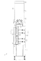
図1に示すように、リニアアクチュエータ1のアクチュエータとしてのエアシリンダ20において、シリンダチューブ21の軸方向一端(図1では右端)は蓋部22により封止されるとともに、軸方向他端(図1では左端)には連結部材23を介して矩形状のベース30が連結されている。ベース30上には矩形状をなすスライドテーブル31が移動可能に支持されている。なお、スライドテーブル31において、ベース30の長さ方向に沿う(スライドテーブル31の往復動方向)方向をスライドテーブル31の長さ方向とするとともに、ベース30及びスライドテーブル31において長さ方向に直交する方向を幅方向とする。
(First embodiment)
A first embodiment of the present invention will be described below with reference to FIGS.
As shown in FIG. 1, in an
図2に示すように、スライドテーブル31の長さ方向一端にはエンドプレート32がボルトB1によって固定されている。また、シリンダチューブ21内には、図示しないピストンがエアシリンダ20の軸方向に移動可能に収容されるとともに、ピストンにはピストンロッド24が取り付けられている。ピストンロッド24は連結部材23を貫通してシリンダチューブ21外に突出している。シリンダチューブ21外へ突出したピストンロッド24の先端にはフローティング部材33が固定されるとともに、このフローティング部材33はエンドプレート32に連結されている。そして、シリンダチューブ21に対するエアの給排により、ピストンロッド24がシリンダチューブ21に対して出没するとともに、スライドテーブル31が移動するようになっている。
As shown in FIG. 2, an
図1に示すように、ベース30の幅方向両側にはガイドレール35がベース30の長さ方向に延びるように互いに平行に固定されている。また、スライドテーブル31の幅方向中央には規制部31cがスライドテーブル31の長さ方向へ延びるように突設されるとともに、スライドテーブル31は幅方向に沿った断面がT字状になっている。スライドテーブル31の幅方向において、規制部31cを挟む位置には、それぞれ一対のガイド部材36がボルトB2により固定されている。
As shown in FIG. 1,
図1及び図2に示すように、各ガイド部材36はガイドレール35の長さ方向に沿った側面に対向配置されるとともに、各ガイド部材36におけるガイドレール35側には複数の転動ボール37が転動可能に支持されている。なお、本実施形態では図3に示すように、ガイド部材36において、規制部31cの側面に対向する面を押圧面36aとする。そして、スライドテーブル31はガイド部材36を介してガイドレール35により直線移動可能に支持されている。すなわち、ピストンロッド24の出没に伴いスライドテーブル31が移動すると転動ボール37が転動するとともにガイドレール35により、スライドテーブル31が円滑に直線移動できるようになっている。なお、規制部31cはガイド部材36の当接によりガイド部材36の移動を規制し、ガイド部材36とガイドレール35の間が必要以上に空くことを規制する。
As shown in FIGS. 1 and 2, each
次に、予圧調整機構について説明する。
スライドテーブル31の一面である上面には、ワーク搭載面31bが形成されるとともに、スライドテーブル31にはワーク搭載面31bからガイド部材36に向かって延びる挿通孔31aが形成されている。挿通孔31aの一端は、ワーク搭載面31bにおけるスライドテーブル31の幅方向の略中央に開口している。また、挿通孔31aの他端は、規制部31cの一側面に開口しており、挿通孔31aは、ガイド部材36の押圧面36aに向けて開口している。そして、挿通孔31aの中心軸Fはワーク搭載面31bに対して斜めに延びているとともに中心軸Fと押圧面36aとの間の角度Θ1は30度になっている。
Next, the preload adjusting mechanism will be described.
A
上記構成の挿通孔31aのワーク搭載面31b側には雌ねじ31eが形成されている。また、挿通孔31aには、押圧部材38とネジ39が挿入されている。本実施形態においては、ネジ39と押圧部材38が軸部材40を構成している。押圧部材38において、ガイド部材36側の先端にはテーパ面38aが形成されている。ネジ39は、押圧部材38に続けて挿通孔31aに挿入され、挿通孔31aの雌ねじ31eに螺合されている。ネジ39の雌ねじ31eに対する螺入に従って押圧部材38が押圧面36aに向かって押圧され、押圧部材38が挿通孔31aに沿って移動するようになっている。押圧部材38がネジ39によって押圧されると、テーパ面38aが押圧面36aを押圧する力(ネジ39の軸力)は、X成分とY成分の分力に分けられる。そして、押圧部材38が押圧面36aを押圧するため、ガイド部材36はX成分に沿った方向へ押圧され、移動する。よって、本実施形態では、傾いて形成された挿通孔31aが軸部材40の分力をテーパ面38aからガイド部材36に作用させる分力作用手段となる。
A
ここで、スライドテーブル31の幅方向に延び、かつ、押圧面36aに直交する仮想面を水平面Hとすると、中心軸Fと水平面Hとの間の角度Θ2は60度になっている。水平面Hはワーク搭載面31bと平行をなし、ワーク搭載面31bと中心軸Fとの間の角度も60度となっている。軸部材40は、挿通孔31aに沿って移動するため、軸部材40と水平面Hとの間の角度も同様に60度となる。このため、軸部材40を距離aだけ移動させた場合、水平面Hに沿った40の移動距離bは、距離aの1/2となっている。
Here, if a virtual plane extending in the width direction of the slide table 31 and orthogonal to the
次に、予圧調整機構の作用及び、ガイドレール35とガイド部材36の間の予圧の調整方法について説明する。
ネジ39が挿通孔31aの雌ねじ31eに螺入されることにより、ネジ39の先端部により押圧部材38が押圧されるとともに、押圧部材38のテーパ面38aがガイド部材36の押圧面36aを押圧する。すると、ガイド部材36は、押圧部材38のX成分の分力により、スライドテーブル31の幅方向に沿ってガイドレール35に向けて移動する。すると、ガイド部材36の転動ボール37がガイドレール35に押し付けられ、ガイドレール35とガイド部材36の間の予圧は大きくなる。一方、予圧を小さくする場合、ネジ39を雌ねじ31eに対し螺退させると、ネジ39による押圧部材38の押圧力が弱まり、X成分の分力によるガイド部材36への押圧力が弱まる結果、予圧が小さくなる。そして、使用者は、ネジ39の螺入量を調整することによりガイドレール35とガイド部材36の間の予圧を所望する値に調整する。その後、使用者は、予圧の調整後、ネジ39を接着剤で固定し、調整を完了する。
Next, the operation of the preload adjusting mechanism and the method for adjusting the preload between the
When the
上記実施形態によれば、以下のような効果を得ることができる。
(1)スライドテーブル31にはワーク搭載面31bからガイド部材36の押圧面36aに向かって斜めに延びる挿通孔31aが形成されるとともに、この挿通孔31aには軸部材40が挿通されている。そして、軸部材40を挿通孔31aに沿って移動させることで、軸部材40の軸力の分力をガイド部材36の押圧面36aに作用させ、分力方向にガイド部材36を移動させることができる。すなわち、予圧調整のために移動させる軸部材40は、ガイド部材36の移動方向ではなく、その移動方向に対し交差する方向に移動する。よって、ガイド部材36は押圧部材38のX成分の分力により押圧される。このため、軸部材40をガイド部材36の移動方向に沿って移動するように配置する必要がなく、リニアアクチュエータ1がスライドテーブル31の幅方向に大型化しない。また、軸部材40はスライドテーブル31の厚みを利用して配置されるため、スライドテーブル31が厚み方向に大型化することもなく、リニアアクチュエータ1全体の大型化を招くこともない。
According to the above embodiment, the following effects can be obtained.
(1) The slide table 31 is formed with an
(2)軸部材40を押圧部材38とネジ39とに分割して構成した。そして、ネジ39の挿通孔31aへの螺入に伴い押圧部材38を押圧面36aに向けて押圧することができる。よって、押圧部材38を回転させることなく挿通孔31aの延びる方向へ移動させることができる。このため、押圧部材38が回転することによって偏心した状態で押圧面36aが押圧されてしまうことを防止することができる。
(2) The
(3)挿通孔31aはワーク搭載面31bに対して60度傾いている。このため、軸部材40を距離aだけ移動させた場合、ワーク搭載面31bに沿った軸部材40の移動距離bは、距離aの1/2となり、ガイドレール35とガイド部材36間における予圧の微妙な調整を容易に行うことができる。
(3) The
(4)スライドテーブル31の幅方向に沿った断面はT字状になっているため、スライドテーブル31の幅方向中央に対する剛性が高められている。したがって、スライドテーブル31の幅方向中央に挿通孔31aを形成しても、スライドテーブル31の変形等を防止することができる。
(第2実施形態)
以下、本発明を具体化した第2実施形態について図4にしたがって説明する。なお、以下に説明する実施形態において、第1実施形態と同一構成については、その重複する説明を省略又は簡略する。
(4) Since the cross section along the width direction of the slide table 31 is T-shaped, the rigidity of the slide table 31 with respect to the center in the width direction is increased. Therefore, even if the
(Second Embodiment)
Hereinafter, a second embodiment of the present invention will be described with reference to FIG. In the embodiment described below, the same description as in the first embodiment is omitted or simplified.
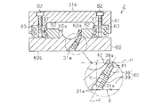
図4に示すように、リニアアクチュエータ2のベース60上には、矩形状をなすスライドテーブル61が移動可能に支持されている。ベース60の幅方向中央には規制部60aがベース60の長さ方向へ伸びるように突設されるとともに、規制部60aを挟む位置には、それぞれ一対のガイドレール62がベース60の長さ方向に延びるように互いに平行に固定されている。
As shown in FIG. 4, a rectangular slide table 61 is movably supported on the
スライドテーブル61の幅方向両側には、ガイド部材63がスライドテーブル61の長さ方向に延びるように互いに平行に固定されている。
各ガイド部材63は、一対のガイドレール62を外側から挟むように対向配置されるとともに、各ガイド部材63におけるガイドレール62側には複数の転動ボール37が転動可能に支持されている。なお、本実施形態ではガイドレール62において、規制部60aの側面に対向する面を押圧面62aとする。
On both sides of the slide table 61 in the width direction, guide
Each
次に、予圧調整機構について説明する。
ベース60には、一面としてのベース下面60bからガイドレール62に向かって斜めに延びる挿通孔31aが形成されている。そして、挿通孔31aの中心軸Fはベース下面60bに対して斜めに延びているとともに中心軸Fと押圧面62aとの間の角度Θ1は30度になっている。なお、挿通孔31aは第1実施形態の挿通孔と構成が同じなので、その説明を省略する。
Next, the preload adjusting mechanism will be described.
The
挿通孔31aには、第1実施形態と同じ軸部材40(押圧部材38とネジ39)が挿入されている。押圧部材38がネジ39によって押圧されると、テーパ面38aが押圧面62aを押圧する力(ネジ39の軸力)は、X成分とY成分の分力に分けられる。そして、押圧部材38が押圧面62aを押圧するため、ガイドレール62はX成分に沿った方向へ押圧され、移動する。よって、本実施形態では、傾いて形成された挿通孔31aが軸部材40の分力をテーパ面38aからガイドレール62に作用させる分力作用手段となる。
The same shaft member 40 (pressing
上記実施形態によれば、以下のような効果を得ることができる。
(5)ベース60にはベース下面60bからガイドレール62の押圧面62aに向かって斜めに延びる挿通孔31aが形成されるとともに、この挿通孔31aには軸部材40が挿通されている。そして、軸部材40を挿通孔31aに沿って移動させることで、軸部材40の軸力の分力をガイドレール62の押圧面62aに作用させ、分力方向にガイドレール62を移動させることができる。すなわち、予圧調整のために移動させる軸部材40は、ガイドレール62の移動方向ではなく、その移動方向に対し交差する方向に移動する。よって、ガイドレール62は押圧部材38のX成分の分力により押圧される。このため、軸部材40をガイドレール62の移動方向に沿って移動するように配置する必要がなく、リニアアクチュエータ2が大型化しない。
According to the above embodiment, the following effects can be obtained.
(5) The
(6)また、挿通孔31aをベース60に形成しても予圧を調整することが可能となり、使用者の用途に合わせて、スライドテーブル61に挿通孔を形成するか、ベース60に挿通孔を形成するかを選択することができるようになる。
(6) In addition, it is possible to adjust the preload even if the
なお、上記実施形態は以下のように変更してもよい。
・第1及び第2実施形態において、軸部材40は、ネジ39のみで構成してもよい。この場合、ネジ39の先端にテーパ面を形成してもよい。
In addition, you may change the said embodiment as follows.
In the first and second embodiments, the
・第1及び第2実施形態において、押圧部材38の先端にテーパ面38aを形成しなくてもよい。
・第1及び第2実施形態において、スライドテーブル31,61の幅方向に沿った断面形状はコ字状でもよい。
In the first and second embodiments, the tapered
-In 1st and 2nd embodiment, the cross-sectional shape along the width direction of the slide tables 31 and 61 may be U shape.
・第1及び第2実施形態において、中心軸Fと水平面Hとの間の角度Θ2は変更してもよい。
・第1実施形態において、図5に示すように、挿通孔31aをワーク搭載面31bに直交する方向に沿って延びる様に形成してもよい。この場合、規制部31cの一方の側面に押圧面36aに向かって延びる傾斜部31dを形成するとともに、押圧面36aと傾斜部31dの間に押圧部材51が設けられる。押圧部材51には、傾斜部31dに摺接するテーパ面51aが形成されるとともに、押圧面36aに接触する接触面51bが形成されている。
In the first and second embodiments, the angle Θ2 between the central axis F and the horizontal plane H may be changed.
-In 1st Embodiment, as shown in FIG. 5, you may form so that the
そして、ネジ39の挿通孔31aへの螺入に伴い、押圧部材51が傾斜部31dによって押圧部材51のX成分に沿った方向へ押圧される。すなわち、挿通孔31a、押圧部材51、テーパ面51a、傾斜部31dが分力作用手段となる。
As the
これによれば、挿通孔31aをワーク搭載面31bに対して斜めに形成しなくてもガイドレール35とガイド部材36の間の予圧を調整することができる。したがって、挿通孔31aを斜めに形成する場合に比べ、容易に挿通孔31aを形成することができる。
According to this, the preload between the
・第1及び第2実施形態ではアクチュエータとしてエアシリンダ20に具体化したが、油圧シリンダに具体化してもよい。
・第1実施形態において、挿通孔31aは、スライドテーブル31の側面からガイド部材36に向かって斜めに延びるように形成されていてもよい。
In the first and second embodiments, the actuator is embodied in the
In the first embodiment, the
・第2実施形態において、挿通孔31aは、ベース60の側面からガイドレール62に向かって斜めに延びるように形成されていてもよい。
In the second embodiment, the
1,2…リニアアクチュエータ、20…アクチュエータとしてのエアシリンダ、30,60…ベース、31,61…スライドテーブル、31a…分力作用手段を構成する挿通孔、31b…一面としてのワーク搭載面、31c,60a…規制部、31d…分力作用手段を構成する傾斜部、31e…雌ねじ、35,62…ガイドレール、36,63…ガイド部材、36a,62a…押圧面、38,51…軸部材及び分力作用手段を構成する押圧部材、38a…テーパ面、39…軸部材を構成するネジ、40…軸部材、51a…分力作用手段を構成するテーパ面、51b…接触面、60b…一面としてのベース下面。
DESCRIPTION OF
Claims (6)
アクチュエータによって往復動し、上面にワーク搭載面を有するスライドテーブルと、
前記スライドテーブルの下面に一体化され、該スライドテーブルを前記ガイドレールに沿って直線移動可能に支持するガイド部材と、を有するリニアアクチュエータに設けられ、前記ガイドレールと前記ガイド部材の間の予圧を調整するリニアアクチュエータの予圧調整機構であって、
前記スライドテーブルの下面に対し交差するように前記ガイド部材に設けられた押圧面と、
前記スライドテーブルの一面から前記押圧面に向けて延びるように前記スライドテーブルに形成された挿通孔と、
前記挿通孔に挿通される軸部材と、
前記軸部材の軸力の分力を前記押圧面から前記ガイド部材に作用させ、前記予圧を発生させるための分力作用手段と、を有することを特徴とするリニアアクチュエータの予圧調整機構。 A guide rail provided on the upper surface of the base;
A slide table that reciprocates by an actuator and has a workpiece mounting surface on the upper surface;
And a guide member that is integrated with a lower surface of the slide table and supports the slide table so as to be linearly movable along the guide rail. A preload between the guide rail and the guide member is provided. A linear actuator preload adjustment mechanism to be adjusted,
A pressing surface provided on the guide member so as to intersect the lower surface of the slide table;
An insertion hole formed in the slide table so as to extend from one surface of the slide table toward the pressing surface;
A shaft member inserted through the insertion hole;
A preload adjusting mechanism for a linear actuator, comprising: component force acting means for causing a component force of an axial force of the shaft member to act on the guide member from the pressing surface to generate the preload.
前記軸部材は、前記押圧面を押圧する押圧部材と、前記雌ねじに螺着され、前記押圧部材を前記押圧面に向けて押圧するネジとから形成されている請求項1に記載のリニアアクチュエータの予圧調整機構。 A female screw is formed in the insertion hole,
2. The linear actuator according to claim 1, wherein the shaft member is formed of a pressing member that presses the pressing surface and a screw that is screwed to the female screw and presses the pressing member toward the pressing surface. Preload adjustment mechanism.
前記分力作用手段は、前記挿通孔に連通し、かつ該挿通孔の軸方向に対し傾斜しつつ前記押圧面に向かって延びる傾斜部と、
前記押圧面に接触する接触面を有するとともに前記傾斜部に摺接するテーパ面を有する前記押圧部材と、から構成されている請求項2に記載のリニアアクチュエータの予圧調整機構。 The insertion hole is formed so as to extend along a direction orthogonal to the workpiece mounting surface,
The component force acting means communicates with the insertion hole and extends toward the pressing surface while being inclined with respect to the axial direction of the insertion hole;
The preload adjusting mechanism for a linear actuator according to claim 2, comprising: a pressing surface that has a contact surface that contacts the pressing surface and a tapered surface that slides on the inclined portion.
アクチュエータによって往復動し、上面にワーク搭載面を有するスライドテーブルと、
前記スライドテーブルの下面に一体化され、該スライドテーブルを前記ガイドレールに沿って直線移動可能に支持するガイド部材と、を有するリニアアクチュエータに設けられ、前記ガイドレールと前記ガイド部材の間の予圧を調整するリニアアクチュエータの予圧調整機構であって、
前記ベースの上面に対し交差するように前記ガイドレールに設けられた押圧面と、
前記ベースの一面から前記押圧面に向けて延びるように前記ベースに形成された挿通孔と、
前記挿通孔に挿通される軸部材と、
前記軸部材の軸力の分力を前記押圧面から前記ガイドレールに作用させ、前記予圧を発生させるための分力作用手段と、を有することを特徴とするリニアアクチュエータの予圧調整機構。 A guide rail provided on the upper surface of the base;
A slide table reciprocated by an actuator and having a workpiece mounting surface on the upper surface;
And a guide member that is integrated with a lower surface of the slide table and supports the slide table so as to be linearly movable along the guide rail. A preload between the guide rail and the guide member is provided. A linear actuator preload adjustment mechanism to be adjusted,
A pressing surface provided on the guide rail so as to intersect the upper surface of the base;
An insertion hole formed in the base so as to extend from one surface of the base toward the pressing surface;
A shaft member inserted through the insertion hole;
A preload adjusting mechanism for a linear actuator, comprising: component force acting means for causing the component force of the axial force of the shaft member to act on the guide rail from the pressing surface to generate the preload.
Priority Applications (1)
| Application Number | Priority Date | Filing Date | Title |
|---|---|---|---|
| JP2011042837A JP5478538B2 (en) | 2011-02-28 | 2011-02-28 | Linear actuator preload adjustment mechanism |
Applications Claiming Priority (1)
| Application Number | Priority Date | Filing Date | Title |
|---|---|---|---|
| JP2011042837A JP5478538B2 (en) | 2011-02-28 | 2011-02-28 | Linear actuator preload adjustment mechanism |
Publications (2)
| Publication Number | Publication Date |
|---|---|
| JP2012180863A true JP2012180863A (en) | 2012-09-20 |
| JP5478538B2 JP5478538B2 (en) | 2014-04-23 |
Family
ID=47012240
Family Applications (1)
| Application Number | Title | Priority Date | Filing Date |
|---|---|---|---|
| JP2011042837A Active JP5478538B2 (en) | 2011-02-28 | 2011-02-28 | Linear actuator preload adjustment mechanism |
Country Status (1)
| Country | Link |
|---|---|
| JP (1) | JP5478538B2 (en) |
Cited By (3)
| Publication number | Priority date | Publication date | Assignee | Title |
|---|---|---|---|---|
| WO2015045699A1 (en) * | 2013-09-27 | 2015-04-02 | Thk株式会社 | Movement unit |
| CN108026965A (en) * | 2015-10-07 | 2018-05-11 | Thk株式会社 | Motion guide device |
| JP2022526578A (en) * | 2019-04-04 | 2022-05-25 | ディッケル マホ プロンテン ゲーエムベーハー | Guide device, precision support for linear rails and adjustment method |
Families Citing this family (1)
| Publication number | Priority date | Publication date | Assignee | Title |
|---|---|---|---|---|
| KR102294595B1 (en) * | 2021-04-12 | 2021-08-26 | 왕순옥 | Transfer guide using a small actuator equipped with a preload module for preventing clearance |
Citations (6)
| Publication number | Priority date | Publication date | Assignee | Title |
|---|---|---|---|---|
| JPS54138647U (en) * | 1978-03-20 | 1979-09-26 | ||
| JPS58143132U (en) * | 1982-03-20 | 1983-09-27 | オイレス工業株式会社 | sliding unit |
| JPS58163819A (en) * | 1982-03-24 | 1983-09-28 | Toshiba Corp | Table mechanism |
| JPS6066426U (en) * | 1983-06-01 | 1985-05-11 | 日立精機株式会社 | Rolling guide device |
| JPS63147231U (en) * | 1987-03-18 | 1988-09-28 | ||
| WO1997041363A1 (en) * | 1996-05-01 | 1997-11-06 | Thk Co., Ltd. | Linear motion guide unit and table guide apparatus utilizing the same |
-
2011
- 2011-02-28 JP JP2011042837A patent/JP5478538B2/en active Active
Patent Citations (6)
| Publication number | Priority date | Publication date | Assignee | Title |
|---|---|---|---|---|
| JPS54138647U (en) * | 1978-03-20 | 1979-09-26 | ||
| JPS58143132U (en) * | 1982-03-20 | 1983-09-27 | オイレス工業株式会社 | sliding unit |
| JPS58163819A (en) * | 1982-03-24 | 1983-09-28 | Toshiba Corp | Table mechanism |
| JPS6066426U (en) * | 1983-06-01 | 1985-05-11 | 日立精機株式会社 | Rolling guide device |
| JPS63147231U (en) * | 1987-03-18 | 1988-09-28 | ||
| WO1997041363A1 (en) * | 1996-05-01 | 1997-11-06 | Thk Co., Ltd. | Linear motion guide unit and table guide apparatus utilizing the same |
Cited By (10)
| Publication number | Priority date | Publication date | Assignee | Title |
|---|---|---|---|---|
| WO2015045699A1 (en) * | 2013-09-27 | 2015-04-02 | Thk株式会社 | Movement unit |
| JP2015068369A (en) * | 2013-09-27 | 2015-04-13 | Thk株式会社 | Movable unit |
| CN105556142A (en) * | 2013-09-27 | 2016-05-04 | Thk株式会社 | Movement unit |
| US9751632B2 (en) | 2013-09-27 | 2017-09-05 | Thk Co., Ltd. | Movement unit |
| CN105556142B (en) * | 2013-09-27 | 2017-11-17 | Thk株式会社 | Mobile unit |
| CN108026965A (en) * | 2015-10-07 | 2018-05-11 | Thk株式会社 | Motion guide device |
| CN108026965B (en) * | 2015-10-07 | 2020-07-10 | Thk株式会社 | Motion guide device |
| JP2022526578A (en) * | 2019-04-04 | 2022-05-25 | ディッケル マホ プロンテン ゲーエムベーハー | Guide device, precision support for linear rails and adjustment method |
| US11819967B2 (en) | 2019-04-04 | 2023-11-21 | Deckel Maho Pfronten Gmbh | Guide device, precision support for a linear rail and adjusting method |
| JP7422164B2 (en) | 2019-04-04 | 2024-01-25 | ディッケル マホ プロンテン ゲーエムベーハー | Guide device, precision support for straight rails and adjustment method |
Also Published As
| Publication number | Publication date |
|---|---|
| JP5478538B2 (en) | 2014-04-23 |
Similar Documents
| Publication | Publication Date | Title |
|---|---|---|
| JP5478538B2 (en) | Linear actuator preload adjustment mechanism | |
| JP2009279698A (en) | Clamp device | |
| CN107900714A (en) | A kind of wedge shape adjustable support tooling | |
| CN102274852B (en) | Three-roller spiral pore type rolling mill | |
| CN104874682A (en) | Indentation-free bending machine lower mold with adjustable opening | |
| CN101480667A (en) | Rolling guide and guard | |
| CN207771309U (en) | A kind of wedge shape adjustable support tooling | |
| CN104550362A (en) | Bending device for bar material | |
| KR101586443B1 (en) | High Speed Press Machine | |
| CN103659357A (en) | Device for positioning special-shaped components with specific structures | |
| CN202592802U (en) | Slide guiding structure of hydraulic machine | |
| CN206106627U (en) | Horizontal register device of modified circular screen printer | |
| CN105268860B (en) | A kind of efficient diel | |
| CN210759470U (en) | Pressing plate device of creasing machine | |
| CN207310213U (en) | A kind of removable guide rail that can keep gypsum mold horizontal movement | |
| CN203937290U (en) | The adjustable laminating machine in a kind of film feeding position | |
| CN203920187U (en) | A kind of mounting structure of carving carving motor in milling machine | |
| CN103659385A (en) | Clamp with adjustable clamping size | |
| CN203592125U (en) | Fan-shaped roller base compensating device | |
| CN206883202U (en) | A kind of installing plate adjusting means | |
| CN202079076U (en) | Three-roller spiral hole rolling mill | |
| CN201058481Y (en) | Locating fine setting device of three-roller calendering mechanism | |
| CN201304461Y (en) | A track base lifting structure of threading machine | |
| CN206375473U (en) | A kind of unwinding shaft stopping means | |
| JP5797625B2 (en) | Linear guide device and linear actuator device |
Legal Events
| Date | Code | Title | Description |
|---|---|---|---|
| A621 | Written request for application examination |
Free format text: JAPANESE INTERMEDIATE CODE: A621 Effective date: 20121017 |
|
| A977 | Report on retrieval |
Free format text: JAPANESE INTERMEDIATE CODE: A971007 Effective date: 20130731 |
|
| A131 | Notification of reasons for refusal |
Free format text: JAPANESE INTERMEDIATE CODE: A131 Effective date: 20130813 |
|
| A521 | Written amendment |
Free format text: JAPANESE INTERMEDIATE CODE: A523 Effective date: 20131007 |
|
| TRDD | Decision of grant or rejection written | ||
| A01 | Written decision to grant a patent or to grant a registration (utility model) |
Free format text: JAPANESE INTERMEDIATE CODE: A01 Effective date: 20140204 |
|
| A61 | First payment of annual fees (during grant procedure) |
Free format text: JAPANESE INTERMEDIATE CODE: A61 Effective date: 20140210 |
|
| R150 | Certificate of patent or registration of utility model |
Ref document number: 5478538 Country of ref document: JP Free format text: JAPANESE INTERMEDIATE CODE: R150 |