JP2012180158A - Remote operation device and operation device - Google Patents
Remote operation device and operation device Download PDFInfo
- Publication number
- JP2012180158A JP2012180158A JP2011043264A JP2011043264A JP2012180158A JP 2012180158 A JP2012180158 A JP 2012180158A JP 2011043264 A JP2011043264 A JP 2011043264A JP 2011043264 A JP2011043264 A JP 2011043264A JP 2012180158 A JP2012180158 A JP 2012180158A
- Authority
- JP
- Japan
- Prior art keywords
- slider
- display
- unit
- touch panel
- changeover switch
- Prior art date
- Legal status (The legal status is an assumption and is not a legal conclusion. Google has not performed a legal analysis and makes no representation as to the accuracy of the status listed.)
- Withdrawn
Links
Images


Classifications
-
- B—PERFORMING OPERATIONS; TRANSPORTING
- B66—HOISTING; LIFTING; HAULING
- B66C—CRANES; LOAD-ENGAGING ELEMENTS OR DEVICES FOR CRANES, CAPSTANS, WINCHES, OR TACKLES
- B66C13/00—Other constructional features or details
- B66C13/18—Control systems or devices
- B66C13/40—Applications of devices for transmitting control pulses; Applications of remote control devices
Abstract
Description
本発明は、タッチパネルディスプレイに移動体を操作するための操作部を表示する遠隔操作装置及び操作装置に関するものである。 The present invention relates to a remote operation device and an operation device that display an operation unit for operating a moving body on a touch panel display.
クレーンといった搬送機械等の移動体を操作する操作装置として、タッチパネルディスプレイが使用され、スイッチなどの操作部がディスプレイ上に表示される場合がある。クレーンがゴムタイヤ式トランスファークレーン(RTG)である場合、操作部が操作されることによって、クレーンの走行速度、吊具の横行速度、吊具の巻上げ速度などが調整されたり、ツイストロック装置が動作したり、吊具が回転したりする。 A touch panel display is used as an operation device for operating a moving body such as a transport machine such as a crane, and an operation unit such as a switch may be displayed on the display. When the crane is a rubber tire type transfer crane (RTG), the operating speed of the crane, the traverse speed of the lifting gear, the lifting speed of the lifting gear, etc. are adjusted by operating the operation unit, and the twist lock device is activated. Or the hanging tool rotates.
特許文献1には、建設機械やクレーンのコントロールパネルとしてタッチ感応パネル(タッチスクリーン)を用い、タッチスクリーン上のスイッチを適切な位置に配置する技術が開示されている。
ところで、搬送機械等の移動体(以下、クレーンを例にして説明する。)を運転する場合、ユーザは、クレーンを直接見ながら、又は操作パネルに表示されたクレーンを確認しながら、操作部を操作することになる。このとき、表面がフラットなタッチパネルディスプレイ上に操作部が表示されている場合、ユーザは、当然触感のみで操作部の表示位置や操作部への入力内容を知ることができない。そのため、ユーザは、クレーンを運転しながら、操作部の表示位置等を目視で確認することになる。 By the way, when driving a moving body such as a transport machine (hereinafter, described as an example of a crane), the user looks at the crane directly or confirms the crane displayed on the operation panel, and moves the operation unit. Will be operated. At this time, when the operation unit is displayed on the touch panel display having a flat surface, the user cannot naturally know the display position of the operation unit and the input content to the operation unit only by touch. Therefore, the user visually checks the display position of the operation unit while operating the crane.
しかし、クレーンの運転中、ユーザは、クレーンの動作状況を常に見ている必要があり、タッチパネルディスプレイ上に表示された操作部を確認できない。そのため、クレーンの操作において、誤操作が発生する可能性がある。 However, during the operation of the crane, the user needs to always watch the operation status of the crane, and cannot check the operation unit displayed on the touch panel display. For this reason, an erroneous operation may occur in the operation of the crane.
本発明は、このような事情に鑑みてなされたものであって、タッチパネルディスプレイを用いて移動体を動作させる場合に、操作部を確認でき、安全に移動体を操作することが可能な遠隔操作装置及び操作装置を提供することを目的とする。 The present invention has been made in view of such circumstances, and when operating a moving body using a touch panel display, a remote operation capable of confirming an operation unit and safely operating the moving body An object is to provide a device and an operation device.
上記課題を解決するために、本発明の遠隔操作装置及び操作装置は以下の手段を採用する。
すなわち、本発明に係る遠隔操作装置は、遠隔地における移動体を表示するモニタ部、及び移動体を操作するための操作部を表示するディスプレイと、操作部に対するユーザの操作を検知する検知部とを有するタッチパネルディスプレイと、検知部にて検知されたユーザの操作に基づいて、移動体を動作させる操作信号を生成する制御部と、操作部の表示位置に対応してタッチパネルディスプレイ上に突出して設けられ、操作部の機能に対応した形状を有する凸部とを備える。
In order to solve the above problems, the remote control device and control device of the present invention employ the following means.
That is, a remote operation device according to the present invention includes a monitor unit that displays a moving body in a remote location, a display that displays an operation unit for operating the mobile unit, and a detection unit that detects a user operation on the operation unit. Provided on the touch panel display corresponding to the display position of the operation unit, and a control unit that generates an operation signal for operating the moving body based on a user operation detected by the detection unit. And a convex part having a shape corresponding to the function of the operation part.
この発明によれば、タッチパネルディスプレイは、ディスプレイと検知部を有し、ディスプレイには、モニタ部及び操作部が表示される。モニタ部には、遠隔地における移動体が表示される。操作部に対するユーザの操作は、検知部によって検知され、制御部によって操作信号が生成される。操作信号は、例えば通信制御部を介して有線又は無線で移動体に送られる。よって、ユーザは、モニタ部を通して移動体の状況を確認でき、ディスプレイに表示された操作部を用いて移動体を操作できる。タッチパネルディスプレイ上には、操作部の表示位置に対応して、操作部の機能に対応した形状を有する凸部が突出して設けられる。したがって、表面がフラットなタッチパネルディスプレイの場合、通常、モニタ部だけでなく、操作部の表示を確認しながら、移動体の操作をしなければならないところ、ユーザは、凸部から触感を得ることによって、操作部を確認することなく、モニタ部の表示だけを見ながら移動体を操作できる。よって、移動体の動作を常に目視で確認しながら操作できるため、タッチパネルディスプレイを用いた操作でも、安全な操作が可能となる。 According to this invention, the touch panel display has a display and a detection unit, and the monitor unit and the operation unit are displayed on the display. A moving body in a remote place is displayed on the monitor unit. A user operation on the operation unit is detected by the detection unit, and an operation signal is generated by the control unit. The operation signal is sent to the mobile body by wire or wireless via, for example, the communication control unit. Therefore, the user can check the state of the moving body through the monitor unit, and can operate the moving body using the operation unit displayed on the display. On the touch panel display, a projection having a shape corresponding to the function of the operation unit is provided so as to protrude corresponding to the display position of the operation unit. Therefore, in the case of a touch panel display having a flat surface, the user usually has to operate the moving body while checking the display of the operation unit as well as the monitor unit. The moving body can be operated while only looking at the display on the monitor unit without checking the operation unit. Accordingly, since the operation of the moving body can be always performed while visually confirming, a safe operation is possible even with an operation using a touch panel display.
上記発明において、操作部は切替えスイッチでもよく、凸部は、切替えスイッチの切替え位置に対応した形状を有してもよい。 In the above invention, the operation part may be a changeover switch, and the convex part may have a shape corresponding to the changeover position of the changeover switch.
この発明によれば、ユーザが凸部の触感によって操作部を操作する際、切替えスイッチの切替え位置に対応した形状を確認しながら、切替えスイッチを切替えることができる。例えば、切替え位置によって異なる形状を有するように凸部が設けられる場合、ユーザは、形状の違いを確認することで、凸部の形状に合わせて切替えスイッチを切替えられる。 According to this invention, when the user operates the operation unit with the tactile sensation of the convex portion, the changeover switch can be changed while confirming the shape corresponding to the changeover position of the changeover switch. For example, when the convex portion is provided so as to have a different shape depending on the switching position, the user can switch the changeover switch according to the shape of the convex portion by checking the difference in shape.
上記発明において、操作部は切替えスイッチでもよく、凸部は、切替えスイッチの中立位置に突出して設けられてもよい。 In the above invention, the operation part may be a changeover switch, and the convex part may be provided to protrude to a neutral position of the changeover switch.
この発明によれば、ユーザが凸部の触感によって操作部を操作する際、切替えスイッチの中立位置に対応した凸部を確認しながら、切替えスイッチを中立位置に切替えたり、中立位置に対していずれか一つの方向に切替えたりすることができる。 According to the present invention, when the user operates the operation unit with the tactile sensation of the convex part, the changeover switch is switched to the neutral position while confirming the convex part corresponding to the neutral position of the changeover switch. Or switch to one direction.
上記発明において、操作部はスライダでもよく、凸部は、スライダの長さ方向に対応して高さが変化してもよい。 In the above invention, the operation portion may be a slider, and the height of the convex portion may change corresponding to the length direction of the slider.
この発明によれば、ユーザが凸部の触感によって操作部を操作する際、スライダの長さ方向に対応した高さを確認しながら、スライダのつまみを移動させることができる。例えば、スライダの長さ方向に沿って次第に高くなるように凸部が設けられる場合、ユーザは、高さの違いを確認することで、凸部の高さに合わせてスライダのつまみを移動させられる。 According to the present invention, when the user operates the operation unit with the tactile sensation of the convex portion, the slider knob can be moved while checking the height corresponding to the length direction of the slider. For example, when the convex portion is provided so as to gradually increase along the length direction of the slider, the user can move the slider knob according to the height of the convex portion by checking the difference in height. .
上記発明において、操作部はスライダでもよく、凸部は、スライダの中立位置に突出して設けられてもよい。 In the above invention, the operation portion may be a slider, and the convex portion may be provided so as to protrude to the neutral position of the slider.
この発明によれば、ユーザが凸部の触感によって操作部を操作する際、スライダの中立位置に対応した凸部を確認しながら、スライダのつまみを中立位置に移動させたり、中立位置に対していずれか一つの方向に移動させたりすることができる。 According to the present invention, when the user operates the operation portion with the tactile sensation of the convex portion, the slider knob is moved to the neutral position while confirming the convex portion corresponding to the neutral position of the slider, or with respect to the neutral position. It can be moved in any one direction.
上記発明において、移動体は、クレーンでもよく、操作部は、クレーンの走行速度の調整、吊具の横行速度の調整、吊具の巻上げ速度及び巻下げ速度の調整、ツイストロック装置のロック及びアンロック、並びに吊具の回転のいずれかの操作に対応してディスプレイに表示されてもよい。 In the above invention, the mobile body may be a crane, and the operation unit may adjust the traveling speed of the crane, adjust the traversing speed of the lifting tool, adjust the lifting speed and lowering speed of the lifting tool, and lock and unlock the twist lock device. You may display on a display corresponding to any operation of a lock | rock and rotation of a hanging tool.
この発明によれば、ユーザは、遠隔操作装置によってクレーンを操作でき、ディスプレイには、クレーンの走行速度の調整、吊具の横行速度の調整、吊具の巻上げ速度の調整、ツイストロック装置のロック及びアンロック、並びに吊具の回転といったクレーンの操作に関する操作部が表示される。このとき、凸部は、クレーンの走行速度、吊具の横行速度又は吊具の巻上げ速度及び巻下げ速度を段階的に調整したり、クレーン又は吊具の進行方向を調整したりするという操作部の機能に対応した形状を有したり、ツイストロック装置を動作させるという操作部の機能に対応した形状を有したり、吊具の回転方向を調整するという操作部の機能に対応した形状を有する。 According to the present invention, the user can operate the crane by the remote control device, and the display includes adjustment of the traveling speed of the crane, adjustment of the traversing speed of the hanging tool, adjustment of the lifting speed of the lifting tool, and locking of the twist lock device. And the operation part regarding operation of a crane, such as unlocking and rotation of a hanging tool, is displayed. At this time, the projecting portion adjusts the traveling speed of the crane, the traversing speed of the hanging tool or the hoisting speed and the lowering speed of the lifting tool in stages, or adjusts the traveling direction of the crane or the lifting tool. It has a shape corresponding to the function of the operation part, has a shape corresponding to the function of the operation part to operate the twist lock device, or has a shape corresponding to the function of the operation part to adjust the rotation direction of the hanging tool. .
また、本発明に係る操作装置は、移動体を操作するための操作部を表示するディスプレイと、操作部に対するユーザの操作を検知する検知部とを有するタッチパネルディスプレイと、検知部にて検知されたユーザの操作に基づいて、移動体を動作させる操作信号を生成する制御部と、操作部の表示位置に対応してタッチパネルディスプレイ上に突出して設けられ、操作部の機能に対応した形状を有する凸部とを備える。 In addition, the operation device according to the present invention is detected by the detection unit, a touch panel display including a display that displays an operation unit for operating the moving body, a detection unit that detects a user operation on the operation unit, and the detection unit. A control unit that generates an operation signal for operating the moving body based on a user's operation, and a protrusion provided on the touch panel display corresponding to the display position of the operation unit and having a shape corresponding to the function of the operation unit A part.
この発明によれば、タッチパネルディスプレイは、ディスプレイと検知部を有し、ディスプレイには、操作部が表示される。操作部に対するユーザの操作は、検知部によって検知され、制御部によって操作信号が生成される。操作信号は、例えば通信制御部を介して有線又は無線で移動体に送られる。よって、ユーザは、ディスプレイに表示された操作部を用いて移動体を操作できる。タッチパネルディスプレイ上には、操作部の表示位置に対応して、操作部の機能に対応した形状を有する凸部が突出して設けられる。したがって、表面がフラットなタッチパネルディスプレイの場合、通常、移動体の動作状況だけでなく、操作部の表示を確認しながら、移動体の操作をしなければならないところ、ユーザは、凸部から触感を得ることによって、操作部を確認することなく、モニタ部の表示だけを見ながら移動体を操作できる。よって、移動体の動作を常に目視で確認しながら操作できるため、タッチパネルディスプレイを用いた操作でも、安全な操作が可能となる。 According to this invention, the touch panel display has a display and a detection unit, and the operation unit is displayed on the display. A user operation on the operation unit is detected by the detection unit, and an operation signal is generated by the control unit. The operation signal is sent to the mobile body by wire or wireless via, for example, the communication control unit. Therefore, the user can operate the moving body using the operation unit displayed on the display. On the touch panel display, a projection having a shape corresponding to the function of the operation unit is provided so as to protrude corresponding to the display position of the operation unit. Therefore, in the case of a touch panel display with a flat surface, the user usually has to operate the moving body while confirming not only the operation status of the moving body but also the display of the operation unit. By obtaining, the moving body can be operated while only looking at the display on the monitor unit without checking the operation unit. Accordingly, since the operation of the moving body can be always performed while visually confirming, a safe operation is possible even with an operation using a touch panel display.
本発明によれば、タッチパネルディスプレイを用いて移動体を動作させる場合に、操作部を確認でき、安全に移動体を操作することができる。 ADVANTAGE OF THE INVENTION According to this invention, when operating a moving body using a touch panel display, an operation part can be confirmed and a moving body can be operated safely.
以下に、本発明に係る実施形態について、図面を参照して説明する。まず、図16を参照して、本実施形態の遠隔操作装置が使用されるコンテナターミナルについて説明する。図16は、コンテナターミナルを示す概略図である。 Embodiments according to the present invention will be described below with reference to the drawings. First, a container terminal in which the remote control device of this embodiment is used will be described with reference to FIG. FIG. 16 is a schematic view showing a container terminal.
図16に示すように、コンテナターミナルTには、岸壁クレーン51と複数のコンテナヤードYが備えられる。岸壁クレーン51は、コンテナ船Sに対してコンテナ(荷物)Cの荷役を行う。コンテナヤードYは、コンテナCを保管する場所である。図16に示すように、各コンテナヤードYには、多数のコンテナCが集積され、コンテナヤードYに集積されたコンテナCを跨ぐようにして、搬送機械としての複数のゴムタイヤ式トランスファークレーン(RTG)52が配置される。各RTG52は、図16中の矢印で示す方向に移動可能である。
As shown in FIG. 16, the container terminal T includes a
コンテナターミナルTには、搬送機械としての複数のトレーラVも配置される。トレーラVは、コンテナヤードYを走行するとともに、岸壁クレーン51とコンテナヤードYとの間を走行する。船積みの際、コンテナヤードY上のコンテナCは、RTG52によってトレーラV上に搭載され、トレーラVによって岸壁クレーン51に運ばれる。そして、コンテナCは、岸壁クレーン51によって船積みされる。一方、荷下ろしの際、コンテナ船S上のコンテナCは、岸壁クレーン51によってトレーラV上に搭載され、トレーラVによってRTG52に運ばれる。そして、コンテナCは、RTG52によってコンテナヤードYに集積される。
In the container terminal T, a plurality of trailers V as a transfer machine are also arranged. The trailer V travels between the container yard Y and the
コンテナターミナルTには管理棟53が設置されている。例えばこの管理棟53に設置されたサーバ装置による制御によって、本実施形態の遠隔操作装置1は、RTG52と無線回線(例えば、無線LAN)によって接続される。遠隔操作装置1は、RTG52を遠隔制御する。
A
次に、本発明の第1実施形態に係る遠隔操作装置1について説明する。以下では、遠隔操作装置1によって、RTG52が操作される場合について説明するが、本発明は、この例に限定されない。例えば、他の形式のクレーン又はクレーン以外の遠隔操作を必要とする移動体が操作される場合に適用してもよい。図17は、本発明の遠隔操作装置を示すブロック図である。
Next, the
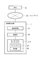
遠隔操作装置1は、例えばパーソナルコンピュータであり、CPU(制御部40)やメモリを備え、プログラムによって演算を行ったり、各種構成要素を制御したりする。また、遠隔操作装置1は、通信制御部41を備え、有線又は無線によってネットワーク60と接続され、各種信号を送受信する。遠隔操作装置1は、RTG52へ操作信号を送信したり、RTG52に設けられたカメラから撮像信号を受信したりする。
The
遠隔操作装置1は、タッチパネルディスプレイ3,4を備える。タッチパネルディスプレイ3,4は、ディスプレイ42及び検知部43を有する。ディスプレイ42は、表示信号に基づいて、カメラによって撮影された映像や、操作対象を操作するためのスイッチやスライダ、操作対象の各種データなどを表示する。検知部43は、ユーザによる接触又は近接を検知する。操作部が表示されている位置に、接触又は近接が検知された場合、その操作部の機能に対応する操作信号が制御部40によって生成される。生成された操作信号は、通信制御部41を介して有線又は無線で操作対象に送信される。
The
次に、図1を参照して、遠隔操作装置1のタッチパネルディスプレイ3,4について説明する。図1は、本発明の第1実施形態に係る遠隔操作装置を示す上面図である。遠隔操作装置1は、図1に示すように、タッチパネルディスプレイ3が上部側に設けられ、タッチパネルディスプレイ4が下部側に設けられる。
Next, the touch panel displays 3 and 4 of the
タッチパネルディスプレイ3には、運転用ガイド表示部12と、ノッチ状態表示インジケータ13と、故障・異常発生状態表示部14と、カメラ映像部15と、荷役作業指示内容表示部16などが表示される。また、タッチパネルディスプレイ4には、巻上げスライダ7と、横行スライダ8と、走行スライダ9と、ツイストロック切替えスイッチ10と、吊具回転スイッチ11と、クレーン状態アニメーション表示部17と、緊急停止スイッチ18と、クレーン電源入切スイッチ19と、自動操作関連スイッチ20と、スプレッダサイズ切替えスイッチ21などが表示される。巻上げスライダ7と、横行スライダ8と、走行スライダ9と、ツイストロック切替えスイッチ10と、吊具回転スイッチ11は、操作部の一例である。
On the touch panel display 3, a driving
運転用ガイド表示部12は、クレーンの運転に関する情報を表示する。ノッチ状態表示インジケータ13は、カメラ映像部15の近くに配置され、巻上げスライダ7、横行スライダ8及び走行スライダ9のノッチ状態を表示する。これによって、ユーザは、手元側を見ることなく、カメラ映像部15の近傍でノッチ状態を確認できる。
The driving
故障・異常発生状態表示部14は、クレーンに故障や異常が発生しているか否かを表示する。カメラ映像部15は、モニタ部の一例であり、クレーンに設けられたカメラが撮影した映像を表示する。図1に示す例では、8面の映像が表示可能になっている。ユーザは、カメラ映像部15における映像を確認しながら、クレーンを操作できる。荷役作業指示内容表示部16は、クレーンが荷役の対象とするコンテナに関する情報、例えば種別、サイズなどを表示する。
The failure / abnormality occurrence
巻上げスライダ7は、ワイヤロープの巻上げ速度及び巻下げ速度を調整するための操作部である。巻上げスライダ7において、中央が中立位置であり、巻上げスライダ7に設けられたつまみが中立位置にあるとき、速度がゼロとなり、吊具の巻上げ又は巻下げは停止する。ユーザは、つまみを中立位置から端部側へ移動させることで、巻上げと巻下げを切替えたり、速度を調整したりすることができる。
The winding
横行スライダ8は、吊具を横行方向に移動させる速度を調整するための操作部である。横行スライダ8において、中央が中立位置であり、横行スライダ8に設けられたつまみが中立位置にあるとき、横行速度がゼロとなり、吊具の横行は停止する。ユーザは、つまみを中立位置から端部側へ移動させることで、横行方向を切替えたり、速度を調整したりすることができる。
The traversing
走行スライダ9は、クレーンが走行路に沿って移動する速度を調整するための操作部である。走行スライダ9において、中央が中立位置であり、走行スライダ9に設けられたつまみが中立位置にあるとき、走行速度がゼロとなり、クレーンの走行は停止する。ユーザは、つまみを中立位置から端部側へ移動させることで、走行方向を切替えたり、速度を調整したりすることができる。なお、走行方向とは、RTG52の場合、RTG52が走行路に沿って走行する方向であり、横行方向とは、走行方向に対して直角方向である。
The
ツイストロック切替えスイッチ10は、吊具にコンテナを固定するツイストロック装置のロック及びアンロックを切替えるための操作部である。ツイストロック切替えスイッチ10において、中央が中立位置であり、ユーザは、つまみを中立位置に対して一方向又は他方向に切替えることで、ツイストロック装置のロック及びアンロックを切替えることができる。
The twist
吊具回転スイッチ11は、吊具の回転入切や回転方向を切替えるための操作部である。吊具回転スイッチ11において、中央が中立位置であり、吊具回転スイッチ11に設けられたつまみが中立位置にあるとき、吊具の回転(スキュー:吊具の鉛直軸周りの回転)は停止する。ユーザは、つまみを中立位置に対して一方向又は他方向に切替えることで、吊具の回転方向を切替えることができる。
The hanging
クレーン状態アニメーション表示部17は、模式的に表したクレーン本体、吊具やコンテナなどを現在の動作状態に合わせて動的に表示する。緊急停止スイッチ18は、クレーンの動作を緊急停止させるためのスイッチである。クレーン電源入切スイッチ19は、クレーンへの電源の入切を切替えるためのスイッチである。自動操作関連スイッチ20は、クレーンの手動運転及び自動運転を切替えるためのスイッチである。スプレッダサイズ切替えスイッチ21は、コンテナサイズに合わせて吊具のスプレッダサイズを切替えるためのスイッチである。
The crane state
巻上げスライダ7、横行スライダ8及び走行スライダ9には、それぞれタッチパネルディスプレイ4上に突出した凸部24,25,26が設けられる。凸部24,25,26は、巻上げスライダ7、横行スライダ8及び走行スライダ9の表示位置に対応して設けられる。
The winding
また、ツイストロック切替えスイッチ10及び吊具回転スイッチ11には、それぞれタッチパネルディスプレイ4上に凸部32,33,26が設けられる。凸部32,33,26は、ツイストロック切替えスイッチ10及び吊具回転スイッチ11の表示位置に対応して設けられる。
Further, the twist
凸部24,25,26,32,33は、例えばシリコーンゴム等の弾性体である。凸部24,25,26,32,33がユーザによって押圧されると、その押圧力はタッチパネルディスプレイ4に伝達され、ユーザ操作として操作信号が生成される。なお、凸部24,25,26,32,33は、巻上げスライダ7、横行スライダ8及び走行スライダ9やツイストロック切替えスイッチ10及び吊具回転スイッチ11上に設けられてもよいし、上側ではなく近傍に設けられてもよい。近傍に設けられる場合は、凸部24,25,26,32,33によって、ユーザがスライダやスイッチの位置を認識できるようにすればよい。そして、タッチパネルディスプレイ4への入力は、凸部24,25,26,32,33を介さずに、タッチパネルディスプレイ4へ直接行われるようにしてもよい。
The
下部側のタッチパネルディスプレイ4が設けられた筐体には、グリップ5が両側面に一つずつ設けられる。これによって、ユーザはグリップ5を握りながら、タッチパネルディスプレイ4上に表示された操作部を容易に操作できる。
A
次に、図3〜図6を用いて、巻上げスライダ7、横行スライダ8及び走行スライダ9に対応して設けられる凸部24,25,26について説明する。ここでは、巻上げスライダ7について説明するが、横行スライダ8及び走行スライダ9についても、巻上げスライダ7と同様の凸部24,25,26が設けられる。
Next, the
巻上げスライダ7は、図3に示すように、一方向に長い形状を有し、つまみ23が長手方向に沿って移動可能である。つまみ23の位置が現在の入力状態を表す。巻上げスライダ7の中間が、中立位置であり、中立位置から一方向の端部側まで、例えば3段階(ノッチ)に入力を変更できるようになっている。端部側に向かうほど、巻上げ速度又は巻き下げ速度が速くなる。巻上げスライダ7上の任意の位置がユーザによって指定されることでつまみ23の位置が変更され、つまみ23の位置に対応した操作信号が生成される。
As shown in FIG. 3, the winding
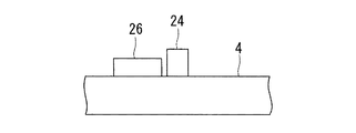
図4に示すように、凸部24は、巻上げスライダ7の表示位置の上面に、中立位置から一端部側まで一方向に長い形状で設けられる。また、凸部25は、中立位置を対称軸にして、凸部24と対称的に設けられ、巻上げスライダ7の表示位置の上面に、中立位置から他端部側まで一方向に長い形状で設けられる。凸部24,25は、図5に示すように、中立位置側の高さが最も低く、端部側の高さが最も高くなるように、タッチパネルディスプレイ4表面に対して傾斜して設けられる。ユーザは、凸部24,25に触れることによって、巻上げスライダ7を目視しないで、巻上げスライダ7の位置を確認でき、さらに、凸部24,25の高さに基づいて、つまみ23の位置を指定することができる。
As shown in FIG. 4, the
図4に示すように、凸部26は、巻上げスライダ7の中間、すなわち中立位置に設けられる。凸部26は、一方向に長い形状であり、一端側がスライダ7近傍に位置し、巻上げスライダ7の長手方向に対して垂直方向に設けられる。ユーザは、凸部26に触れることによって、巻上げスライダ7を目視しないで、巻上げスライダ7の中立位置を確認でき、容易に中立位置を指定できる。
As shown in FIG. 4, the
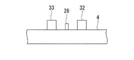
次に、図10〜図13を用いて、ツイストロック切替えスイッチ10に対応して設けられる凸部32,33,26について説明する。ここでは、ツイストロック切替えスイッチ10について説明するが、吊具回転スイッチ11についても、ツイストロック切替えスイッチ10と同様の凸部32,33,26が設けられる。
Next, the
ツイストロック切替えスイッチ10は、図10に示すように、四角形状の指示部30とつまみ31からなる。指示部30には、つまみ31が指示することが可能な目盛りが記されており、つまみ31の指示する方向が現在の入力状態を表す。ツイストロック切替えスイッチ10の中間が、中立位置であり、中立位置に対して右側及び左側に入力を変更できるようになっている。中立位置に対して右側又は左側を指定することで、吊具のツイストロック装置がロック又はアンロックされる。ツイストロック切替えスイッチ10上の任意の位置がユーザによって指定されることでつまみ31の位置が変更され、つまみ31の位置に対応した操作信号が生成される。
As shown in FIG. 10, the twist
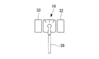
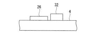
図11〜図13に示すように、凸部32,33は、直方体形状であり、凸部32は、ツイストロック切替えスイッチ10の右側に設けられ、凸部33は、ツイストロック切替えスイッチ10の左側に設けられる。また、凸部26は、巻上げスライダ7の場合と同様に、ツイストロック切替えスイッチ10の中間、すなわち中立位置に設けられる。凸部26は、一方向に長い形状であり、一端側がツイストロック切替えスイッチ10近傍に位置し、他端側がツイストロック切替えスイッチ10から離隔した位置に設けられる。
As shown in FIGS. 11 to 13, the
ユーザは、凸部32,33,26に触れることによって、ツイストロック切替えスイッチ10を目視しないで、ツイストロック切替えスイッチ10の位置を確認でき、さらに、凸部32,33,26の配置関係に基づいて、ツイストロック切替えスイッチ10におけるつまみ31の位置を容易に指定することができる。
The user can confirm the position of the twist
次に、本発明の第2実施形態について、図2を用いて説明する。
遠隔操作装置2は、第1実施形態の遠隔操作装置1と異なり、単一のタッチパネルディスプレイ6のみを備える。タッチパネルディスプレイ6は、タッチパネルディスプレイ3,4と同様に、ディスプレイ42及び検知部43を有する。
Next, a second embodiment of the present invention will be described with reference to FIG.
Unlike the
遠隔操作装置2のタッチパネルディスプレイ6は、第1実施形態の遠隔操作装置1に対して、運転用ガイド表示部12やクレーン状態アニメーション表示部17が表示されない。タッチパネルディスプレイ6には、ノッチ状態表示インジケータ13と、故障・異常発生状態表示部14と、カメラ映像部15と、荷役作業指示内容表示部16と、巻上げスライダ7と、横行スライダ8と、走行スライダ9と、ツイストロック切替えスイッチ10と、吊具回転スイッチ11と、緊急停止スイッチ18と、クレーン電源入切スイッチ19と、自動操作関連スイッチ20と、スプレッダサイズ切替えスイッチ21などが表示される。
The
次に、図7〜図9を用いて、巻上げスライダ7、横行スライダ8及び走行スライダ9に対応して設けられる凸部28,29,26について説明する。ここでは、巻上げスライダ7について説明するが、横行スライダ8及び走行スライダ9についても、巻上げスライダ7と同様の凸部28,29,26が設けられる。
Next, the
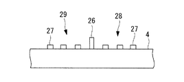
第1実施形態で示した凸部24,25は、一方向に長い部材であり、部材高さによってノッチ位置が確認できるように配置されている。一方、図7〜図9に示すように、凸部28,29は、複数の部材、例えば円柱部27から構成されてもよい。凸部28,29は、図7に示すように、中立位置側の円柱部27の個数が一つであり、端部側の円柱部27の個数が三つであり、その中間の円柱部27の個数が二つである。
The
ユーザは、凸部28,29に触れることによって、巻上げスライダ7を目視しないで、巻上げスライダ7の位置を確認でき、さらに、凸部28,29における円柱部27の配置関係に基づいて、つまみ23の位置を指定することができる。また、ユーザは、凸部26に触れることによって、巻上げスライダ7を目視しないで、巻上げスライダ7の中立位置を確認でき、容易に中立位置を指定できる。
The user can confirm the position of the hoisting
なお、ユーザがスライダのつまみの指定先(ノッチ位置、中立位置)を特定することができれば、凸部の形状や配置関係は、上述した例に限定されない。例えば、凸部は、中立位置から一端部側まで一方向に長い形状で設けられ、中立位置から一端部側に向けて次第に幅が広くなるようにしてもよい。また、凸部を複数の部材で構成する場合、円柱部27のように、円柱形状に限定されず、他の形状、例えば四角柱形状などでもよい。さらに、凸部を構成するため、同一形状の部材を複数配置するのではなく、様々な形状の部材を組み合わせて配置してもよい。またさらに、図7に示す例では、ノッチ位置を表すため、中立位置から端部まで円柱部27が1〜3個へと増える組み合わせを示したが、この例に限定されず、他の数の組み合わせでノッチ位置を表してもよい。
In addition, as long as the user can specify the designation destination (notch position, neutral position) of the slider knob, the shape and the arrangement relationship of the convex portions are not limited to the above-described example. For example, the convex portion may be provided in a shape that is long in one direction from the neutral position to the one end side, and the width may gradually increase from the neutral position toward the one end side. Further, when the convex portion is constituted by a plurality of members, the
次に、図14及び図15を用いて、ツイストロック切替えスイッチ10や吊具回転スイッチ11に対応して設けられる凸部について説明する。ここでは、ツイストロック切替えスイッチ10について説明するが、吊具回転スイッチ11についても、ツイストロック切替えスイッチ10と同様の凸部が設けられる。
Next, the convex part provided corresponding to the
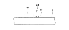
図14の例では、ツイストロック切替えスイッチ10には、凸部34,35,26が設けられる。
図14に示すように、凸部34は、直方体形状であり、ツイストロック切替えスイッチ10の右側に設けられ、凸部35は、円柱形状であり、ツイストロック切替えスイッチ10の左側に設けられる。また、凸部26は、ツイストロック切替えスイッチ10の中間、すなわち中立位置に設けられる。ユーザは、凸部34,35,26に触れることによって、凸部34,35,26の形状や配置関係に基づいて、ツイストロック切替えスイッチ10におけるつまみ31の位置を容易に指定することができる。
In the example of FIG. 14, the twist
As shown in FIG. 14, the
図15の例では、ツイストロック切替えスイッチ10には、凸部37,38,26が設けられる。
図15に示すように、凸部37,38は、複数の円柱部36からなる。凸部37は、二つの円柱部36が凸部26の長さ方向に対して垂直方向に配置されたものであり、凸部38は、二つの円柱部36が凸部26の長さ方向に対して垂直方向に配置されたものである。ユーザは、凸部37,38,26に触れることによって、凸部34,35,26の形状や配置関係に基づいて、ツイストロック切替えスイッチ10におけるつまみ31の位置を容易に指定することができる。
In the example of FIG. 15, the twist
As shown in FIG. 15, the
なお、ユーザが切替えスイッチのつまみの指定先を特定することができれば、凸部の形状や配置関係は、上述した例に限定されない。例えば、凸部は、円柱形状や直方体形状に限定されず、他の形状でもよい。また、凸部を複数の部材で構成する場合、二つの部材を配置するのではなく、三つ以上の部材を配置してもよいし、複数の部材を直線状に配置するのではなく、例えば三つの部材を三角形に配置するなどしてもよい。 In addition, as long as the user can specify the designation destination of the knob of the changeover switch, the shape and the arrangement relationship of the convex portions are not limited to the above-described example. For example, the convex portion is not limited to a cylindrical shape or a rectangular parallelepiped shape, and may have another shape. Further, when the convex portion is composed of a plurality of members, two or more members may be disposed instead of arranging the two members, and the plurality of members are not disposed linearly, for example, You may arrange | position three members in a triangle.
以上、本発明の実施形態によれば、タッチパネルディスプレイを用いてクレーンといった搬送機械等の移動体を動作させる場合に、ユーザは、凸部から触感を得ることによって、操作部を目視で確認することなく、モニタ部の表示だけを見ながら移動体を操作できる。よって、移動体の動作を常に目視で確認しながら操作できるため、タッチパネルディスプレイを用いた操作でも、安全な操作が可能となる。 As described above, according to the embodiment of the present invention, when moving a moving body such as a crane such as a crane using a touch panel display, the user visually confirms the operation unit by obtaining a tactile sensation from the convex portion. In addition, the moving body can be operated while only looking at the display on the monitor. Accordingly, since the operation of the moving body can be always performed while visually confirming, a safe operation is possible even with an operation using a touch panel display.
なお、上記実施形態では、操作部のノッチ位置や切替え位置は、操作部自身の表示やノッチ状態表示インジケータ13にて確認可能であるが、さらにスライダや切替えスイッチを変更したとき、音声を出力して、ユーザが操作結果を確認できるようにしてもよい。例えば、巻上げ速度、横行速度、走行速度を変更したときは、実際のRTG52のモータ音に合わせて、速度に応じて出力する音を大きくしたり、小さくしたりしてもよい。また、例えばツイストロック装置を操作したときは、入力状態に応じた音を出力したり、実際に「ロック」、「アンロック」といった言葉を出力したりしてもよい。
In the above embodiment, the notch position and switching position of the operation unit can be confirmed by the display of the operation unit itself or the notch
また、上記実施形態では、遠隔操作装置1,2がカメラ映像部15を表示して、ユーザが、カメラ映像部15によって、RTG52の操作状態を確認する場合について説明したが、本発明はこの例に限定されない。例えば、遠隔操作装置1,2がカメラ映像部15を表示せず、ユーザが、直接RTG52等の移動体の操作状態を確認する場合についても、本発明を適用できる。すなわち、操作装置が移動体の運転台に設けられる場合や、ユーザが直接移動体を目視しながら操作装置を操作する場合に、本発明の操作装置によれば、タッチパネルディスプレイを用いた操作装置でも安全な操作が可能となる。
In the above embodiment, the case where the
1,2 遠隔操作装置
3,4,6 タッチパネルディスプレイ
7 巻上げスライダ(操作部,スライダ)
8 横行スライダ(操作部,スライダ)
9 走行スライダ(操作部,スライダ)
10 ツイストロック切替えスイッチ(操作部,切替えスイッチ)
11 吊具回転スイッチ(操作部,切替えスイッチ)
15 カメラ映像部(モニタ部)
24,25,26,28,29,32,33,34,35,37,38 凸部
27,36 円柱部
40 制御部
41 通信制御部
42 ディスプレイ
43 検知部
52 RTG(ゴムタイヤ式トランスファークレーン)
60 ネットワーク
1, 2,
8 Horizontal slider (operation unit, slider)
9 Traveling slider (operation unit, slider)
10 Twist lock selector switch (operation unit, selector switch)
11 Lifter rotation switch (operation unit, changeover switch)
15 Camera image section (monitor section)
24, 25, 26, 28, 29, 32, 33, 34, 35, 37, 38
60 network
Claims (7)
前記検知部にて検知された前記ユーザの操作に基づいて、前記移動体を動作させる操作信号を生成する制御部と、
前記操作部の表示位置に対応して前記タッチパネルディスプレイ上に突出して設けられ、前記操作部の機能に対応した形状を有する凸部と、
を備える遠隔操作装置。 A touch panel display having a monitor for displaying a moving body in a remote place, a display for displaying an operating section for operating the moving body, and a detecting section for detecting a user operation on the operating section;
Based on the user operation detected by the detection unit, a control unit that generates an operation signal for operating the moving body;
A convex part provided on the touch panel display so as to correspond to the display position of the operation part, and having a shape corresponding to the function of the operation part,
A remote control device comprising:
前記凸部は、前記切替えスイッチの切替え位置に対応した形状を有する請求項1に記載の遠隔操作装置。 The operation unit is a changeover switch,
The remote control device according to claim 1, wherein the convex portion has a shape corresponding to a switching position of the changeover switch.
前記凸部は、前記切替えスイッチの中立位置に突出して設けられる請求項1又は2に記載の遠隔操作装置。 The operation unit is a changeover switch,
The remote control device according to claim 1, wherein the convex portion is provided to protrude to a neutral position of the changeover switch.
前記凸部は、前記スライダの長さ方向に対応して高さが変化する請求項1に記載の遠隔操作装置。 The operation unit is a slider;
The remote control device according to claim 1, wherein the height of the convex portion changes in accordance with the length direction of the slider.
前記凸部は、前記スライダの中立位置に突出して設けられる請求項1又は4に記載の遠隔操作装置。 The operation unit is a slider;
The remote control device according to claim 1, wherein the convex portion is provided to protrude to a neutral position of the slider.
前記操作部は、前記クレーンの走行速度の調整、吊具の横行速度の調整、吊具の巻上げ速度及び巻下げ速度の調整、ツイストロック装置のロック及びアンロック、並びに吊具の回転のいずれかの操作に対応して前記ディスプレイに表示される請求項1から5のいずれか1項に記載の遠隔操作装置。 The moving body is a crane,
The operation unit is one of adjusting the traveling speed of the crane, adjusting the traversing speed of the lifting tool, adjusting the lifting speed and lowering speed of the lifting tool, locking and unlocking the twist lock device, and rotating the lifting tool. The remote control device according to any one of claims 1 to 5, wherein the remote control device is displayed on the display in response to the operation.
前記検知部にて検知された前記ユーザの操作に基づいて、前記移動体を動作させる操作信号を生成する制御部と、
前記操作部の表示位置に対応して前記タッチパネルディスプレイ上に突出して設けられ、前記操作部の機能に対応した形状を有する凸部と、
を備える操作装置。
A touch panel display having a display for displaying an operation unit for operating the moving body, and a detection unit for detecting a user operation on the operation unit;
Based on the user operation detected by the detection unit, a control unit that generates an operation signal for operating the moving body;
A convex part provided on the touch panel display so as to correspond to the display position of the operation part, and having a shape corresponding to the function of the operation part,
An operating device comprising:
Priority Applications (2)
| Application Number | Priority Date | Filing Date | Title |
|---|---|---|---|
| JP2011043264A JP2012180158A (en) | 2011-02-28 | 2011-02-28 | Remote operation device and operation device |
| PCT/JP2011/060114 WO2012117574A1 (en) | 2011-02-28 | 2011-04-26 | Remote operation apparatus, and operation apparatus |
Applications Claiming Priority (1)
| Application Number | Priority Date | Filing Date | Title |
|---|---|---|---|
| JP2011043264A JP2012180158A (en) | 2011-02-28 | 2011-02-28 | Remote operation device and operation device |
Publications (1)
| Publication Number | Publication Date |
|---|---|
| JP2012180158A true JP2012180158A (en) | 2012-09-20 |
Family
ID=46757530
Family Applications (1)
| Application Number | Title | Priority Date | Filing Date |
|---|---|---|---|
| JP2011043264A Withdrawn JP2012180158A (en) | 2011-02-28 | 2011-02-28 | Remote operation device and operation device |
Country Status (2)
| Country | Link |
|---|---|
| JP (1) | JP2012180158A (en) |
| WO (1) | WO2012117574A1 (en) |
Cited By (1)
| Publication number | Priority date | Publication date | Assignee | Title |
|---|---|---|---|---|
| WO2021193293A1 (en) * | 2020-03-24 | 2021-09-30 | 住友重機械搬送システム株式会社 | Rtg remote operation system and rtg remote operation method |
Families Citing this family (1)
| Publication number | Priority date | Publication date | Assignee | Title |
|---|---|---|---|---|
| CN109319663B (en) * | 2018-12-06 | 2020-09-15 | 中联重科股份有限公司 | Control method and device for crane and crane |
Family Cites Families (4)
| Publication number | Priority date | Publication date | Assignee | Title |
|---|---|---|---|---|
| JPH07319623A (en) * | 1994-05-25 | 1995-12-08 | Canon Inc | Touch panel type liquid crystal display |
| JP2002274779A (en) * | 2001-03-15 | 2002-09-25 | Daido Steel Co Ltd | Overhead crane operating device |
| JP2005072773A (en) * | 2003-08-21 | 2005-03-17 | Sony Corp | Mode switching control method and electronic apparatus |
| JP2010165337A (en) * | 2008-12-15 | 2010-07-29 | Sony Corp | Information processing apparatus, information processing method and program |
-
2011
- 2011-02-28 JP JP2011043264A patent/JP2012180158A/en not_active Withdrawn
- 2011-04-26 WO PCT/JP2011/060114 patent/WO2012117574A1/en active Application Filing
Cited By (1)
| Publication number | Priority date | Publication date | Assignee | Title |
|---|---|---|---|---|
| WO2021193293A1 (en) * | 2020-03-24 | 2021-09-30 | 住友重機械搬送システム株式会社 | Rtg remote operation system and rtg remote operation method |
Also Published As
| Publication number | Publication date |
|---|---|
| WO2012117574A1 (en) | 2012-09-07 |
Similar Documents
| Publication | Publication Date | Title |
|---|---|---|
| US20070034587A1 (en) | Crane, preferably crawler or truck crane | |
| JP6985519B2 (en) | Cargo crane with operating device and operating device | |
| CN107922172B (en) | Control of a lifting device | |
| WO2017159319A1 (en) | Crane work assistance device | |
| WO2012117574A1 (en) | Remote operation apparatus, and operation apparatus | |
| US11802025B2 (en) | Remote control workstation | |
| CN108358081B (en) | Working method of intelligent tower crane system capable of realizing automatic hoisting | |
| CN105217503A (en) | Double hook operation-control system and method and hang people's jacking system | |
| WO2012023309A1 (en) | Operation panel for remote operation system | |
| JP6458558B2 (en) | Operation control device for traveling cargo handling machine and traveling cargo handling machine | |
| JP2020169087A (en) | Positioning method of crane hoisting accessory and crane system | |
| JP2009023753A (en) | Three-dimensional space carrying device and three-dimensional space carrying method | |
| JP7182955B2 (en) | Cargo handling equipment and method of operating the cargo handling equipment | |
| JP2008265934A (en) | Working machine operation information display system | |
| US11958724B2 (en) | Work vehicle | |
| CN115243993A (en) | Remote operation system and remote operation method | |
| KR101730622B1 (en) | Apparatus for controlling hoist movement | |
| JP6778982B2 (en) | Operation system for cargo handling equipment | |
| JP2021151920A (en) | Crane work management system and management unit | |
| JP7411514B2 (en) | Crane operation system and crane operation instruction method | |
| US20200307966A1 (en) | Crane controller | |
| US10829348B2 (en) | Working machine and operation system for working machine | |
| KR102132481B1 (en) | Crane anti-collision system | |
| WO2021193293A1 (en) | Rtg remote operation system and rtg remote operation method | |
| JP2015048226A (en) | Elevator control device |
Legal Events
| Date | Code | Title | Description |
|---|---|---|---|
| A711 | Notification of change in applicant |
Free format text: JAPANESE INTERMEDIATE CODE: A712 Effective date: 20120824 |
|
| A300 | Withdrawal of application because of no request for examination |
Free format text: JAPANESE INTERMEDIATE CODE: A300 Effective date: 20140513 |