JP2012176453A - Drill reamer - Google Patents
Drill reamer Download PDFInfo
- Publication number
- JP2012176453A JP2012176453A JP2011040243A JP2011040243A JP2012176453A JP 2012176453 A JP2012176453 A JP 2012176453A JP 2011040243 A JP2011040243 A JP 2011040243A JP 2011040243 A JP2011040243 A JP 2011040243A JP 2012176453 A JP2012176453 A JP 2012176453A
- Authority
- JP
- Japan
- Prior art keywords
- drill
- reamer
- blade
- grooves
- round
- Prior art date
- Legal status (The legal status is an assumption and is not a legal conclusion. Google has not performed a legal analysis and makes no representation as to the accuracy of the status listed.)
- Pending
Links
Images


Abstract
Description
本発明は、ドリル加工用のドリル刃とリーマ加工用のリーマ刃とを備えたドリルリーマに関する。 The present invention relates to a drill reamer provided with a drill blade for drilling and a reamer blade for reamer processing.
従来、ドリルボディの先端側に、ドリル加工を行うための一対のドリル刃の他、これらドリル刃の最大外径よりも大きな最大外径を有するリーマ加工を行うための一対のリーマ刃を設けたドリルリーマが提案されている(特許文献1参照)。このドリルリーマを、回転軸を中心として回転させると、先ずドリル刃によって工作物が削り取られ下穴が形成される。次いで、ドリル刃によって形成された下穴の内周面がリーマ刃によって削り取られ、滑らかな内周面の穴が形成される。このように、ドリルリーマによれば、1つの工程で、2種類の加工を行うことができる。 Conventionally, in addition to a pair of drill blades for drilling, a pair of reamer blades for performing a reaming process having a maximum outer diameter larger than the maximum outer diameter of the drill blades is provided on the tip side of the drill body. A drill reamer has been proposed (see Patent Document 1). When the drill reamer is rotated about the rotation axis, the workpiece is first scraped off by the drill blade to form a pilot hole. Next, the inner peripheral surface of the prepared hole formed by the drill blade is scraped off by the reamer blade to form a smooth inner peripheral surface hole. Thus, according to the drill reamer, two types of processing can be performed in one step.
しかしながら、特許文献1に示されたドリルリーマにおいて、リーマ加工時、すなわちリーマ刃で下穴の内周面を削っている時に、加工穴の内周面に摺接しドリルリーマを進行方向へガイドするのは、リーマ刃となるDIAチップの基端側に形成された円弧面(特許文献1の図6中、符号46で示す部分)のみである。このため、リーマ加工時におけるドリルリーマのガイド機能が十分でなく、回転軸がぶれてしまう場合がある。これに対しては、加工穴の内周面に摺接する円弧面の数を増やすことでガイド機能を向上させることができるものの、この場合、十分な大きさの切粉排出溝を確保することができず、切粉排出性が低下するおそれがある。 However, in the drill reamer shown in Patent Document 1, when reaming, that is, when the inner peripheral surface of the prepared hole is being cut with a reamer blade, the drill reamer is slidably contacted with the inner peripheral surface of the processed hole and guided in the traveling direction. , Only the arc surface formed on the base end side of the DIA tip serving as a reamer blade (portion indicated by reference numeral 46 in FIG. 6 of Patent Document 1). For this reason, the guide function of the drill reamer at the time of reamer processing is not sufficient, and the rotation axis may be shaken. For this, the guide function can be improved by increasing the number of arcuate surfaces in sliding contact with the inner peripheral surface of the machining hole, but in this case, a sufficiently large chip discharge groove can be secured. There is a risk that the chip dischargeability may be reduced.
本発明は、十分なガイド機能と切粉排出性とを兼ね備えたドリルリーマを提供することを目的とする。 An object of this invention is to provide the drill reamer which has sufficient guide function and chip discharge | emission property.
上記目的を達成するため本発明は、円柱状のドリルボディ(例えば、後述のドリルボディ11)と、前記ドリルボディ側部に、回転軸線を対称軸として対称に形成された一対のドリル溝(例えば、後述のドリル溝12a,12b)と、当該ドリル溝の回転方向後方側の端縁に先行刃として設けられたドリル刃(例えば、後述のドリル刃用のチップ31a,31b,51a,51b)と、前記ドリルボディ側部のうち前記ドリル溝に対し略90度位相の異なる部分に、前記回転軸線を対称軸として対称に形成された一対のリーマ溝(例えば、後述のリーマ溝13a,13b)と、当該リーマ溝の回転方向後方側の端部に後続刃として設けられたリーマ刃(例えば、後述のリーマ刃用のチップ32a,32b、又はリーマ刃用のチップ52a,52b)と、を備えたドリルリーマ(例えば、後述のドリルリーマ1)を提供する。前記ドリルボディには、前記ドリル刃と連設し前記リーマ刃の最大外径と略同径の第1丸ランド(例えば、後述の第1丸ランド36a,36b,56a,56b)と、前記リーマ刃と連設し当該リーマ刃の最大外径と略同径の第2丸ランド(例えば、後述の第2丸ランド37a,37b,57a,57b)と、が形成され、前記ドリル溝は、断面視で略二等辺三角形であり、その回転方向前方側の端縁には、前記第2丸ランドと略同径の第3丸ランド(例えば、後述の第3丸ランド38a,38b,58a,58b)が形成されている。
In order to achieve the above object, the present invention provides a cylindrical drill body (e.g.,
本発明では、ドリルボディ側部に一対のドリル溝及びこれらドリル溝に対し略90度位相の異なるリーマ溝を形成し、これらドリル溝及びリーマ溝のそれぞれの回転方向後方側の端部に先行刃としてのドリル刃と後続刃としてのリーマ刃とを設けた。これにより、ドリル刃によるドリル加工とリーマ刃によるリーマ加工とを1つの工程で行うことができる。
また、ドリル溝を断面視で略二等辺三角形としたので、ドリル刃でワークを切削することで生じた切粉を排出するための切粉排出溝として十分な深さを確保することができる。また、ドリル溝を深くする分、溝の幅を狭くすることにより、ドリル溝とリーマ溝との間に区画されるリーマランドを大きくすることができるので、リーマ刃のバックメタルを大きく確保し、ひいては加工精度を向上することができる。またさらに、ドリル溝を断面視で略二等辺三角形とすることにより、十分な断面二次モーメントを確保し、刃先の剛性を向上することができる。また、ドリルボディには、ドリル刃と連設しリーマ刃の最大外径と略同径の第1丸ランドと、リーマ刃と連設しこのリーマ刃の最大外径と略同径の第2丸ランドとを形成し、さらにドリル溝の回転方向前方の端縁すなわちリーマランドの回転方向後方の端部にこれら第2丸ランドと略同径の第3丸ランドを形成した。これにより、第1、第2、第3丸ランドの3種類の丸ランドにより加工時におけるドリルボディをガイドすることができるので、加工精度をさらに向上することができる。
In the present invention, a pair of drill grooves and reamer grooves having a phase difference of approximately 90 degrees with respect to the drill grooves are formed on the side of the drill body, and the leading blades are provided at the end portions on the rear side in the rotation direction of the drill grooves and the reamer grooves. As a drill blade and a reamer blade as a trailing blade. Thereby, drilling with a drill blade and reaming with a reamer blade can be performed in one step.
Moreover, since the drill groove has a substantially isosceles triangle shape in cross-sectional view, a sufficient depth can be secured as a chip discharge groove for discharging chips generated by cutting the workpiece with the drill blade. In addition, by making the drill groove deeper, by narrowing the groove width, the reamer land partitioned between the drill groove and the reamer groove can be increased, ensuring a large back metal for the reamer blade, As a result, the processing accuracy can be improved. Furthermore, by making the drill groove into a substantially isosceles triangle in a cross-sectional view, a sufficient secondary moment of section can be ensured and the rigidity of the cutting edge can be improved. Also, the drill body is connected to the drill blade and has a first round land having a diameter substantially the same as the maximum outer diameter of the reamer blade, and a second land having a diameter substantially the same as the maximum outer diameter of the reamer blade. Round lands were formed, and further, third round lands having the same diameter as those of the second round lands were formed at the front edge of the drill groove in the rotational direction, that is, at the rear end of the reamer land in the rotational direction. Thereby, since the drill body at the time of a process can be guided by three types of round lands of a 1st, 2nd, 3rd round land, a process precision can further be improved.
以下、本発明の一実施形態を図面に基づいて説明する。
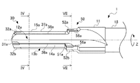
図1及び図2は、本発明の一実施形態に係るドリルリーマ1の構成を示す側面図である。図3は、ドリルリーマ1の構成を示す正面図であり、このドリルリーマ1の回転軸線Z方向に沿って先端側から視た図である。図4は、図1の線IV−IVに沿った断面図である。
Hereinafter, an embodiment of the present invention will be described with reference to the drawings.
FIG.1 and FIG.2 is a side view which shows the structure of the drill reamer 1 which concerns on one Embodiment of this invention. FIG. 3 is a front view showing the configuration of the drill reamer 1 and is a view seen from the front end side along the rotation axis Z direction of the drill reamer 1. 4 is a sectional view taken along line IV-IV in FIG.
ドリルリーマ1は、円柱状のドリルボディ11と、このドリルボディ11を同軸に支持し、ドリルリーマ1の基端側を構成するシャンク18と、を含んで構成される。シャンク18は、図示しない工作機械の主軸に装着される。この工作機械は、ドリルリーマ1を、回転軸線Zを中心軸として回転させながら、この回転軸線Z方向に沿って進退させる。なお、図2は、図1に示す状態から回転軸線Zを中心軸とし、先端側から視て時計周りに90度回転させた場合におけるドリルリーマ1の側面図である。なお、本実施形態では、図3中、反時計周りをドリルリーマ1の回転方向とする。
The drill reamer 1 includes a
回転軸線Zに沿って延びるドリルボディ11は、先端側の前段部30よりも基端側の後段部50の方がその最大外径が大きくなるように形成されている。また、これら前段部30及び後段部50の先端側には、後に詳述するように複数の刃が外周に沿って設けられている。したがって、このドリルリーマ1によれば、前段部30の最大外径に応じた大きさの内径を有する穴と、後段部50の最大外径に応じた大きさの内径を有する穴との2つの異なる大きさの内周面を有する2段の加工穴が形成される。なお、図3には、図示を明確にするため、ドリルボディ11のうち後段部50を除く前段部30の構成のみを示す。
The
図3に示すように、ドリルボディ11の側部には、一対のドリル溝12a,12bが回転軸線Zを対称軸として対称に形成されている。また、ドリルボディ11の側部のうち、これらドリル溝12a,12bに対し略90度位相の異なる部分には、一対のリーマ溝13a,13bが、回転軸線Zを対称軸として対称に形成されている。これらドリル溝12a,12b及びリーマ溝13a,13bは、それぞれ、ドリルボディ11の側部に前段部30及び後段部50の両方にわたり回転軸線Zと平行に形成されている(図1及び図2参照)。
As shown in FIG. 3, a pair of
図4に示すように、リーマ溝13a,13bは、断面視で略L字状である。ドリル溝12a,12bは、断面視で略二等辺三角形であり、かつ上記リーマ溝13a,13bよりも深く形成されている。また、以上のような複数の溝により、ドリルボディ11にはランドが区画形成される。すなわち、ドリル溝12aとリーマ溝13bとの間及びドリル溝12bとリーマ溝13bとの間には、それぞれドリルランド14a,14bが形成され、リーマ溝13aとドリル溝12aとの間及びリーマ溝13bとドリル溝12bとの間には、それぞれリーマランド15a,15bが形成される。
As shown in FIG. 4, the
次に、前段部30の構成について説明する。
図3に示すように、ドリル溝12a,12bを区画する溝側面のうち回転方向後方側の縁部には、それぞれドリル刃用のチップ31a,31b及びこれらチップ31a,31bを支承する台座33a,33bが、ろう付けされている。ドリルボディ11のうちこれらチップ31a,31bの先端側には所定の切刃角のドリル刃16a,16bが形成されている。リーマ溝13a,13bを区画する2つの溝側面のうち回転方向後方側の縁部には、リーマ刃用のチップ32a,32b及びこれらチップ32a,32bを支承する台座34a,34bが、ろう付けされている。これらチップ31a,31b,32a,32bには、例えばダイヤモンドが用いられ、台座33a,33b,34a,34bには、例えば超硬合金が用いられる。
Next, the structure of the front |
As shown in FIG. 3, on the edge portion on the rear side in the rotational direction among the groove side surfaces that define the
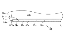
図5は、前段部30のうちドリル溝12a及びドリル刃用のチップ31aの部分拡大正面図である。
図5に示すように、ドリル刃16a(16b)は、回転軸線Zに対し傾斜するように所定の切刃角で直線状に形成されている。また、ドリル刃用のチップ31a(31b)の先端部311a(311b)は、ドリル刃16a(16b)と同じ切刃角で直線状に形成されており、上記ドリル刃16a(16b)と面一になっている。このドリルリーマ1のうち前段部30においては、ドリル刃16a(16b)及びドリル刃用のチップ31a(31b)の先端部311a(311b)が先行刃を構成する。
FIG. 5 is a partially enlarged front view of the
As shown in FIG. 5, the
図5に示すように、ドリル刃用のチップ31a(31b)の先端側には段差部が形成されており、その外周面は上記先行刃の最大外径と略同径の円弧状に形成され、ドリル用丸ランド35a(35b)となっている。
また、ドリルランド14aのうち上記チップ31a(31b)より基端側には、このチップ31a(31b)と連設し後述のリーマ刃用のチップ32a(32b)の最大外径と略同径の円弧状の面が形成されており、第1丸ランド36a(36b)となっている。この第1丸ランド36a,36bは、回転軸線Zと平行に延在する。
As shown in FIG. 5, a step portion is formed on the tip side of the
Further, in the
図6は、前段部30のうちリーマ溝13a及びリーマ刃用のチップ32aの部分拡大正面図である。なお図6には、リーマ刃用のチップ32aに対し位相の異なる部分に設けられたドリル刃用のチップ31aを、比較のため同じ平面内に示す。
FIG. 6 is a partially enlarged front view of the
図6に示すように、リーマ刃用のチップ32a(32b)の先端部321a(321b)は、ドリル刃16a(16b)とほぼ同じ切刃角で直線状に形成されている。また、このチップ32a(32b)の先端部321a(321b)は、ドリル刃用のチップ31a(32b)より基端側に設けられている。さらにリーマ刃用のチップ32a(32b)の先端部321a(321b)の最大外径は、上記ドリル刃用のチップ31a(31b)の最大外径よりも大きくなるように設けられている。したがって、このドリルリーマ1のうち前段部30においては、リーマ刃用のチップ32a(32b)の先端部321a(321b)が、上記先行刃に対する後続刃を構成する。
また、リーマランド15a(15b)のうち上記チップ32a(32b)より基端側には、チップ32a(32a)と連設しこのチップ32a(32b)の最大外径と略同径の円弧状の面が形成されており、第2丸ランド37aとなっている。この第2丸ランド37aは、回転軸線Zと平行に延在する。
As shown in FIG. 6, the
Further, in the
図4に示すように、ドリル溝12a,12bの回転方向前方側の端縁、すなわちリーマランド15a,15bの回転方向後方側の端縁には、それぞれ上述の第1丸ランド36a,36b及び第2丸ランド37a,37bと略同径の第3丸ランド38a,38bが形成されている。これら第3丸ランド38a,38bも、上述の第2丸ランド37a,37bと同様に、回転軸線Zと平行に延在する。また、リーマランド15a,15bのうち第2丸ランド37a,37bと第3丸ランド38a,38bとの間は平取り面39a,39bとなっている。また、第1丸ランド36a,36b、第2丸ランド37a,37b、及び第3丸ランド38a,38bの中では、第3丸ランド38a,38bが最も幅広になっている。
As shown in FIG. 4, the above-mentioned first round lands 36a and 36b and the above-mentioned first round lands 36a and 36b are respectively provided on the front edges of the
次に、後段部50の構成について説明する。
図7は、図1の線VII−VIIに沿った断面図、すなわち後段部50の構成を示す断面図である。
後段部50には、上述の前段部30と同様に、ドリル溝12a,12bを区画する溝側面のうち回転方向後方側の縁部には、それぞれドリル刃用のチップ51a,51b及びこれらチップ51a,51bを支承する台座53a,53bが、ろう付けされている。リーマ溝13a,13bを区画する2つの溝側面のうち回転方向後方側の縁部には、リーマ刃用のチップ52a,52b及びこれらチップ52a,52bを支承する台座54a,54bが、ろう付けされている。これらチップ51a,51b,52a,52bには、例えばダイヤモンドが用いられ、台座53a,53b,54a,54bには、例えば超硬合金が用いられる。
Next, the configuration of the
FIG. 7 is a cross-sectional view taken along line VII-VII in FIG. 1, that is, a cross-sectional view showing the configuration of the
In the
リーマ刃用のチップ52a,52bは、その先端部がドリル刃用のチップ51a,51bの先端部よりも基端側に位置するように、かつその最大外径はドリル刃用のチップ51a,51bの最大外径よりも大きくなるように設けられている。したがって、後段部50においても、ドリル刃用のチップ51a,51bが先行刃を構成し、リーマ刃用のチップ52a,52bが後続刃を構成する。
The
また、後段部50側のドリルランド14a,14b及びリーマランド15a,15bには、前段部30側と同様に、リーマ刃用のチップ52a,52bの最大外径と略同径の第1丸ランド56a,56b、第2丸ランド57a,57b、及び第3丸ランド58a,58bが形成されている。
Also, the drill lands 14a, 14b and the reamer lands 15a, 15b on the
以上のように構成されたドリルリーマ1により、ワークに穴を開ける手順について説明する。
先ず、回転軸線Zを中心軸として回転させつつ、ワークに接近させると、ドリルボディ11の前段部30に設けられたドリル刃16a,16b及びドリル刃用のチップ31a,31bの先端部311a,311bが当接し、ワークを削り取り、下穴を形成する。
さらにドリルリーマ1を前進させると、リーマ刃用のチップ32a,32bの先端部321a,321bが、上記ドリル刃によって形成された下穴の内周面に当接し、この内周面を滑らかに仕上げる。また、このときドリルボディ11は、第1丸ランド36a,36b、第2丸ランド37a,37b及び第3丸ランド38a,38bの6つの円弧状に形成された面を介して加工穴の内周面に摺接するので、加工中における回転軸線Zのぶれを抑制することができる。
A procedure for making a hole in a workpiece by the drill reamer 1 configured as described above will be described.
First, when rotating around the rotation axis Z as a central axis and approaching the workpiece, the
When the drill reamer 1 is further advanced, the
さらにドリルリーマ1を前進させると、後段部50に設けられたドリル刃用のチップ51a,51b及びリーマ刃用のチップ52a,52bの順で上記加工穴に当接し、前段部30と同様に滑らかな内周面を備えた加工穴が形成される。以上により、前段部30と後段部50の外径に応じた大きさの内径を有する2段の加工穴がワークに形成される。
When the drill reamer 1 is further moved forward, the
本実施形態のドリルリーマ1によれば、以下の効果を奏する。
ドリルボディ11側部に一対のドリル溝12a,12b及びこれらドリル溝に対し略90度位相の異なるリーマ溝13a,13bを形成し、これらドリル溝及びリーマ溝のそれぞれの回転方向後方側の端部に先行刃としてのドリル刃用のチップ31a,31bと後続刃としてのリーマ刃用のチップ32a,32bとを設けた。これにより、ドリル刃によるドリル加工とリーマ刃によるリーマ加工とを1つの工程で行うことができる。
また、ドリル溝12a,12bを断面視で略二等辺三角形としたので、ドリル刃でワークを切削することで生じた切粉を排出するための切粉排出溝として十分な深さを確保することができる。また、このようにドリル溝12a,12bを深くする分、溝の幅を狭くすることにより、ドリル溝12a,12bとリーマ溝13a,13bとの間に区画されるリーマランド15a,15bを大きくすることができるので、リーマ刃のバックメタルを大きく確保し、ひいては加工精度を向上することができる。またさらに、ドリル溝12a,12bを断面視で略二等辺三角形とすることにより、十分な断面二次モーメントを確保し、刃先の剛性を向上することができる。また、ドリルボディ11には、ドリル刃用のチップ31a,31bと連設しリーマ刃用のチップ32a,32bの最大外径と略同径の第1丸ランド36a,36bと、リーマ刃用のチップ32a,32bと連設しこのリーマ刃用のチップ32a,32bの最大外径と略同径の第2丸ランド37a,37bとを形成し、さらにドリル溝12a,12bの回転方向前方の端縁すなわちリーマランド15a,15bの回転方向後方の端部にこれら丸ランド36a,36b,37a,37bと略同径の第3丸ランド38a,38bを形成した。これにより、第1丸ランド36a,36b、第2丸ランド37a,37b、及び第3丸ランド38a,38bの3種類の丸ランドにより加工時におけるドリルボディ11をガイドすることができるので、加工精度をさらに向上することができる。
According to the drill reamer 1 of this embodiment, there exist the following effects.
A pair of
In addition, since the
なお、本発明は、上述した実施形態に限るものではなく、種々の変形が可能である。 In addition, this invention is not restricted to embodiment mentioned above, A various deformation | transformation is possible.
1…ドリルリーマ
11…ドリルボディ
12a,12b…ドリル溝
13a,13b…リーマ溝
30…前段部
31a,31b…ドリル刃用のチップ(ドリル刃)
32a,32b…リーマ刃用のチップ(リーマ刃)
35a,35b…ドリル用丸ランド
36a,36b…第1丸ランド
37a,37b…第2丸ランド
38a,38b…第3丸ランド
50…後段部
51a,51b…ドリル刃用のチップ(ドリル刃)
52a,52b…リーマ刃用のチップ(リーマ刃)
56a,56b…第1丸ランド
57a,57b…第2丸ランド
58a,58b…第3丸ランド
DESCRIPTION OF SYMBOLS 1 ...
32a, 32b ... Reamer blade tips (reamer blades)
35a, 35b ... round lands for
52a, 52b ... Reamer blade tips (reamer blades)
56a, 56b ... 1st round land 57a, 57b ... 2nd
Claims (1)
前記ドリルボディ側部に、回転軸線を対称軸として対称に形成された一対のドリル溝と、
当該ドリル溝の回転方向後方側の端縁に先行刃として設けられたドリル刃と、
前記ドリルボディ側部のうち前記ドリル溝に対し略90度位相の異なる部分に、前記回転軸線を対称軸として対称に形成された一対のリーマ溝と、
当該リーマ溝の回転方向後方側の端部に後続刃として設けられたリーマ刃と、を備えたドリルリーマであって、
前記ドリルボディには、前記ドリル刃と連設し前記リーマ刃の最大外径と略同径の第1丸ランドと、前記リーマ刃と連設し当該リーマ刃の最大外径と略同径の第2丸ランドと、が形成され、
前記ドリル溝は、断面視で略二等辺三角形であり、その回転方向前方側の端縁には、前記第2丸ランドと略同径の第3丸ランドが形成されていることを特徴とするドリルリーマ。 A cylindrical drill body;
A pair of drill grooves formed symmetrically about the axis of rotation on the side of the drill body;
A drill blade provided as a leading blade at the edge on the rear side in the rotational direction of the drill groove;
A pair of reamer grooves formed symmetrically with respect to the axis of rotation as a symmetry axis in a portion having a phase difference of approximately 90 degrees with respect to the drill groove in the side of the drill body,
A drill reamer provided with a reamer blade provided as a trailing blade at the end of the reamer groove in the rotational direction rear side,
The drill body is connected to the drill blade and has a first round land having a diameter substantially the same as the maximum outer diameter of the reamer blade, and is connected to the reamer blade and has a diameter substantially the same as the maximum outer diameter of the reamer blade. A second round land is formed,
The said drill groove is a substantially isosceles triangle by sectional view, The 3rd round land of the substantially same diameter as the said 2nd round land is formed in the edge of the rotation direction front side, It is characterized by the above-mentioned. Drill reamer.
Priority Applications (1)
| Application Number | Priority Date | Filing Date | Title |
|---|---|---|---|
| JP2011040243A JP2012176453A (en) | 2011-02-25 | 2011-02-25 | Drill reamer |
Applications Claiming Priority (1)
| Application Number | Priority Date | Filing Date | Title |
|---|---|---|---|
| JP2011040243A JP2012176453A (en) | 2011-02-25 | 2011-02-25 | Drill reamer |
Publications (1)
| Publication Number | Publication Date |
|---|---|
| JP2012176453A true JP2012176453A (en) | 2012-09-13 |
Family
ID=46978689
Family Applications (1)
| Application Number | Title | Priority Date | Filing Date |
|---|---|---|---|
| JP2011040243A Pending JP2012176453A (en) | 2011-02-25 | 2011-02-25 | Drill reamer |
Country Status (1)
| Country | Link |
|---|---|
| JP (1) | JP2012176453A (en) |
Cited By (4)
| Publication number | Priority date | Publication date | Assignee | Title |
|---|---|---|---|---|
| CN102922008A (en) * | 2012-10-31 | 2013-02-13 | 中国北车集团大连机车车辆有限公司 | Drilling tool |
| CN103418845A (en) * | 2013-08-14 | 2013-12-04 | 重庆长安汽车股份有限公司 | Reaming and extruding cutter |
| JP2020203353A (en) * | 2019-06-18 | 2020-12-24 | 真辺工業株式会社 | Rotary cutting tool |
| JP7112584B2 (en) | 2018-09-25 | 2022-08-03 | 匯専科技集團股▲フン▼有限公司 | Diamond cutting tools for hard brittle and difficult-to-cut materials |
Citations (7)
| Publication number | Priority date | Publication date | Assignee | Title |
|---|---|---|---|---|
| FR764041A (en) * | 1933-11-18 | 1934-05-14 | Cie De Construction De Forets | Twist Drill Improvements |
| JPS6360514U (en) * | 1986-10-08 | 1988-04-22 | ||
| JPS6442815U (en) * | 1987-09-05 | 1989-03-14 | ||
| JPH0253321U (en) * | 1988-10-08 | 1990-04-17 | ||
| JP2009255209A (en) * | 2008-04-15 | 2009-11-05 | Sumitomo Electric Hardmetal Corp | Double-margined drill |
| JP2010277409A (en) * | 2009-05-29 | 2010-12-09 | Toshiba Corp | Representative sentence extracting device and program |
| US20130058734A1 (en) * | 2011-02-27 | 2013-03-07 | Vladimir D. Volokh | Combined drill and reamer tool |
-
2011
- 2011-02-25 JP JP2011040243A patent/JP2012176453A/en active Pending
Patent Citations (7)
| Publication number | Priority date | Publication date | Assignee | Title |
|---|---|---|---|---|
| FR764041A (en) * | 1933-11-18 | 1934-05-14 | Cie De Construction De Forets | Twist Drill Improvements |
| JPS6360514U (en) * | 1986-10-08 | 1988-04-22 | ||
| JPS6442815U (en) * | 1987-09-05 | 1989-03-14 | ||
| JPH0253321U (en) * | 1988-10-08 | 1990-04-17 | ||
| JP2009255209A (en) * | 2008-04-15 | 2009-11-05 | Sumitomo Electric Hardmetal Corp | Double-margined drill |
| JP2010277409A (en) * | 2009-05-29 | 2010-12-09 | Toshiba Corp | Representative sentence extracting device and program |
| US20130058734A1 (en) * | 2011-02-27 | 2013-03-07 | Vladimir D. Volokh | Combined drill and reamer tool |
Cited By (5)
| Publication number | Priority date | Publication date | Assignee | Title |
|---|---|---|---|---|
| CN102922008A (en) * | 2012-10-31 | 2013-02-13 | 中国北车集团大连机车车辆有限公司 | Drilling tool |
| CN103418845A (en) * | 2013-08-14 | 2013-12-04 | 重庆长安汽车股份有限公司 | Reaming and extruding cutter |
| JP7112584B2 (en) | 2018-09-25 | 2022-08-03 | 匯専科技集團股▲フン▼有限公司 | Diamond cutting tools for hard brittle and difficult-to-cut materials |
| JP2020203353A (en) * | 2019-06-18 | 2020-12-24 | 真辺工業株式会社 | Rotary cutting tool |
| JP7074348B2 (en) | 2019-06-18 | 2022-05-24 | 真辺工業株式会社 | Reamer |
Similar Documents
| Publication | Publication Date | Title |
|---|---|---|
| JP5909565B2 (en) | Drill and method of manufacturing cut product using the same | |
| WO2018079489A1 (en) | Cutting tool and method for producing cutting workpiece | |
| JP6343005B2 (en) | Drill and method of manufacturing cut product using the same | |
| JP4897836B2 (en) | Drill insert and drill, and work material cutting method | |
| JP6470307B2 (en) | Drill and method of manufacturing cut product using the same | |
| JP2012176453A (en) | Drill reamer | |
| US10821526B2 (en) | Rotary tool and method for manufacturing machined product | |
| JP5675524B2 (en) | Cutting tool | |
| JP2013208692A (en) | Drill and method for manufacturing cutting workpiece using the same | |
| WO2018123937A1 (en) | Drill and method for producing machined workpiece using same | |
| JP6941047B2 (en) | Manufacturing method for rotary tools and cuttings | |
| JP6462364B2 (en) | THROW-AWAY TYPE DRILL AND METHOD FOR MANUFACTURING CUTTING PRODUCT USING THE SAME | |
| JP6110496B2 (en) | Drill and method of manufacturing cut product using the same | |
| JP2005305610A (en) | Twist drill | |
| JP2013035101A (en) | Reamer | |
| JP2010162643A (en) | Drill and grinding method of the drill | |
| JP2009241239A (en) | Drill and boring machining method | |
| JP4979392B2 (en) | Cutting tool unit and cutting tool used for the cutting tool unit | |
| JP6294095B2 (en) | Drill and method of manufacturing cut product using the same | |
| JP6342662B2 (en) | Drill and method of manufacturing cut product using the same | |
| JP6410544B2 (en) | Drill and cutting method | |
| JP5882846B2 (en) | Reamer, cutting tool, and method of manufacturing a cut product using the same | |
| JP2010264531A (en) | Cutting-edge replaceable drill | |
| JP5259751B2 (en) | Reamer | |
| JP5988353B2 (en) | Drill and method of manufacturing cut product using the same |
Legal Events
| Date | Code | Title | Description |
|---|---|---|---|
| A621 | Written request for application examination |
Free format text: JAPANESE INTERMEDIATE CODE: A621 Effective date: 20131127 |
|
| A977 | Report on retrieval |
Free format text: JAPANESE INTERMEDIATE CODE: A971007 Effective date: 20140910 |
|
| A131 | Notification of reasons for refusal |
Free format text: JAPANESE INTERMEDIATE CODE: A131 Effective date: 20140916 |
|
| A521 | Written amendment |
Free format text: JAPANESE INTERMEDIATE CODE: A523 Effective date: 20141117 |
|
| A02 | Decision of refusal |
Free format text: JAPANESE INTERMEDIATE CODE: A02 Effective date: 20150331 |