JP2012176335A - Microbubble generator - Google Patents
Microbubble generator Download PDFInfo
- Publication number
- JP2012176335A JP2012176335A JP2011039274A JP2011039274A JP2012176335A JP 2012176335 A JP2012176335 A JP 2012176335A JP 2011039274 A JP2011039274 A JP 2011039274A JP 2011039274 A JP2011039274 A JP 2011039274A JP 2012176335 A JP2012176335 A JP 2012176335A
- Authority
- JP
- Japan
- Prior art keywords
- annular
- main passage
- gas
- liquid
- case
- Prior art date
- Legal status (The legal status is an assumption and is not a legal conclusion. Google has not performed a legal analysis and makes no representation as to the accuracy of the status listed.)
- Granted
Links
- 239000007788 liquid Substances 0.000 claims abstract description 153
- 230000002093 peripheral effect Effects 0.000 claims description 13
- 239000007789 gas Substances 0.000 description 165
- XLYOFNOQVPJJNP-UHFFFAOYSA-N water Substances O XLYOFNOQVPJJNP-UHFFFAOYSA-N 0.000 description 72
- 230000006870 function Effects 0.000 description 16
- 230000000694 effects Effects 0.000 description 14
- 238000000746 purification Methods 0.000 description 14
- 230000007423 decrease Effects 0.000 description 10
- 239000012530 fluid Substances 0.000 description 10
- QVGXLLKOCUKJST-UHFFFAOYSA-N atomic oxygen Chemical compound [O] QVGXLLKOCUKJST-UHFFFAOYSA-N 0.000 description 8
- 230000005587 bubbling Effects 0.000 description 8
- 238000004519 manufacturing process Methods 0.000 description 8
- 239000001301 oxygen Substances 0.000 description 8
- 229910052760 oxygen Inorganic materials 0.000 description 8
- 230000000704 physical effect Effects 0.000 description 8
- 238000004140 cleaning Methods 0.000 description 6
- 238000009826 distribution Methods 0.000 description 6
- 239000000463 material Substances 0.000 description 6
- 239000013535 sea water Substances 0.000 description 6
- 241000251468 Actinopterygii Species 0.000 description 4
- IJGRMHOSHXDMSA-UHFFFAOYSA-N Atomic nitrogen Chemical compound N#N IJGRMHOSHXDMSA-UHFFFAOYSA-N 0.000 description 4
- CURLTUGMZLYLDI-UHFFFAOYSA-N Carbon dioxide Chemical compound O=C=O CURLTUGMZLYLDI-UHFFFAOYSA-N 0.000 description 4
- 241000238557 Decapoda Species 0.000 description 4
- 241000196324 Embryophyta Species 0.000 description 4
- 238000005273 aeration Methods 0.000 description 4
- 230000015572 biosynthetic process Effects 0.000 description 4
- 238000004891 communication Methods 0.000 description 4
- 230000008602 contraction Effects 0.000 description 4
- 230000003247 decreasing effect Effects 0.000 description 4
- 238000002474 experimental method Methods 0.000 description 4
- 239000013505 freshwater Substances 0.000 description 4
- 230000006872 improvement Effects 0.000 description 4
- 230000005389 magnetism Effects 0.000 description 4
- 238000005259 measurement Methods 0.000 description 4
- 238000000034 method Methods 0.000 description 4
- 230000000149 penetrating effect Effects 0.000 description 4
- 230000001737 promoting effect Effects 0.000 description 4
- 238000005086 pumping Methods 0.000 description 4
- 230000035939 shock Effects 0.000 description 4
- 239000004094 surface-active agent Substances 0.000 description 4
- 230000004083 survival effect Effects 0.000 description 4
- 239000002351 wastewater Substances 0.000 description 4
- 240000008067 Cucumis sativus Species 0.000 description 2
- 235000009849 Cucumis sativus Nutrition 0.000 description 2
- 241000588724 Escherichia coli Species 0.000 description 2
- 241000227653 Lycopersicon Species 0.000 description 2
- 235000007688 Lycopersicon esculentum Nutrition 0.000 description 2
- CBENFWSGALASAD-UHFFFAOYSA-N Ozone Chemical compound [O-][O+]=O CBENFWSGALASAD-UHFFFAOYSA-N 0.000 description 2
- 241000220324 Pyrus Species 0.000 description 2
- 240000004808 Saccharomyces cerevisiae Species 0.000 description 2
- 235000014680 Saccharomyces cerevisiae Nutrition 0.000 description 2
- 241000607142 Salmonella Species 0.000 description 2
- 244000061458 Solanum melongena Species 0.000 description 2
- 235000002597 Solanum melongena Nutrition 0.000 description 2
- 241000191967 Staphylococcus aureus Species 0.000 description 2
- 230000009471 action Effects 0.000 description 2
- 239000003570 air Substances 0.000 description 2
- 230000008827 biological function Effects 0.000 description 2
- 239000013590 bulk material Substances 0.000 description 2
- 229910002092 carbon dioxide Inorganic materials 0.000 description 2
- 239000001569 carbon dioxide Substances 0.000 description 2
- 238000005266 casting Methods 0.000 description 2
- 239000000919 ceramic Substances 0.000 description 2
- 238000012790 confirmation Methods 0.000 description 2
- 239000000470 constituent Substances 0.000 description 2
- 230000007797 corrosion Effects 0.000 description 2
- 238000005260 corrosion Methods 0.000 description 2
- 238000005520 cutting process Methods 0.000 description 2
- 239000012153 distilled water Substances 0.000 description 2
- 235000013399 edible fruits Nutrition 0.000 description 2
- 230000007613 environmental effect Effects 0.000 description 2
- 238000001125 extrusion Methods 0.000 description 2
- 239000011521 glass Substances 0.000 description 2
- 238000009434 installation Methods 0.000 description 2
- 238000005304 joining Methods 0.000 description 2
- 230000000366 juvenile effect Effects 0.000 description 2
- 239000002184 metal Substances 0.000 description 2
- 239000003595 mist Substances 0.000 description 2
- 238000000465 moulding Methods 0.000 description 2
- 229910052757 nitrogen Inorganic materials 0.000 description 2
- 230000005789 organism growth Effects 0.000 description 2
- 235000021017 pears Nutrition 0.000 description 2
- 230000001766 physiological effect Effects 0.000 description 2
- 230000008569 process Effects 0.000 description 2
- 230000009467 reduction Effects 0.000 description 2
- 230000000630 rising effect Effects 0.000 description 2
- 235000015170 shellfish Nutrition 0.000 description 2
- 235000020083 shōchū Nutrition 0.000 description 2
- 239000000126 substance Substances 0.000 description 2
- 239000008399 tap water Substances 0.000 description 2
- 235000020679 tap water Nutrition 0.000 description 2
- 239000011882 ultra-fine particle Substances 0.000 description 2
- 238000009827 uniform distribution Methods 0.000 description 2
- 238000011144 upstream manufacturing Methods 0.000 description 2
- 235000013311 vegetables Nutrition 0.000 description 2
- 238000012795 verification Methods 0.000 description 2
- 239000011800 void material Substances 0.000 description 2
Images


Landscapes
- Mixers With Rotating Receptacles And Mixers With Vibration Mechanisms (AREA)
- Farming Of Fish And Shellfish (AREA)
- Water Treatment By Electricity Or Magnetism (AREA)
Abstract
Description
本発明は、液体中にマイクロメートルサイズの微細気泡を発生させるマイクロバブル発生器に関する。 The present invention relates to a microbubble generator that generates micrometer-sized fine bubbles in a liquid.
液体中に発生したマイクロメートルオーダーサイズの微細気泡は、気泡体積が微細であるため、例えば直径5ミリメートル以上程度等の通常のサイズの気泡に比して上昇速度が遅く長い間液体中に滞在し続ける、気泡サイズが小さいほど水による表面張力の影響によって気泡内圧が高くなり気体は水中に溶解する、等の特質を有しており、このため、生理活性作用による植物や養殖物の収率向上、水質浄化、機械装置の洗浄、排水中の界面活性剤除去機能を利用して多方面の分野において利用価値を有することが知られるようになっている。このような有用な機能を有するマイクロバブルを液体中に発生させる装置は、液体中で多くの微細気泡を発生させること及び微細気泡発生の確実さを備えたものであることが良い性能を有する条件である。マイクロバブルの発生器については例えば従来、特許文献1、2において提案されたものがある。
Micrometer-order microbubbles generated in the liquid have a small bubble volume, so the rising speed is slower than that of normal size bubbles such as a diameter of about 5 mm or more. Continued, the smaller the bubble size, the higher the internal pressure of the bubble due to the effect of surface tension caused by water, and the gas dissolves in water. In addition, it has become known to have utility value in various fields by utilizing water purification, cleaning of mechanical devices, and the function of removing surfactants in waste water. An apparatus for generating microbubbles having such a useful function in a liquid is a condition that generates a large number of microbubbles in the liquid and has a good performance to have certainty of generating microbubbles. It is. For example, there have been conventionally proposed microbubble generators in
特許文献1のマイクロバブル発生装置は、筒状のケーシング4内に二重筒状に整流筒体6を配置し、ケーシングと整流筒体の間隙に第1プロペラ形翼列7を設置するとともに整流筒体内に第2プロペラ形翼列8を設置し、気体導入ポート17に連通する小孔18によりケーシング内に気体を導入させることにより、気液混合流体を内外逆回りの旋回流としてマイクロバブル発生を促進させるものである。しかしながら、特許文献1の装置では、ケーシングと整流筒体との間、並びに整流筒体内に流体をらせん状に案内する羽根等を設置した構造であり、製造が容易ではなくコスト増となるばかりか気体導入部は小孔18一箇所のみで形成されているのでマイクロバブル発生量が限られ、マイクロバブルに特有の機能を充分に発揮させることができないという問題があった。
また、特許文献2は、横長筒体状のケーシングの長手中央をスロート部6とし、一端側にコーン形部5、他端側に末広ノズル部7を形成して流路23で連通したマイクロバブル発生器において、内部に圧送空気の通気路4を設けた進退ロッド8をコーン形部5内に設置してスロート部への進退ロッド先端部の進退動作によりスロート部を通過する液体量を調整しながらマイクロバブルを発生させることを企図したものである。しかしながら、この特許文献2の装置においても気体導入は進退ロッド先端のピンホール42のみにより行なわれるもので、マイクロバブル発生量自体を増加させるものではない。また、文献2の装置は、文献1のものと同様に気泡サイズのばらつきが大きく、ミリサイズ以上の気泡も多く含まれる結果、気泡の多くが大気と接する界面へ上昇し、そのために水中で収縮する気泡の数が少なく水の物理的性質による応用分野での有利な効果を充分に得ることができない、という問題があった。
In the microbubble generator of
本発明は上記従来の課題に鑑みてなされたものであり、その目的は、簡単な構成で低コストで製作でき、また多くの微細気泡を発生させるばかりでなく、マイクロメートルサイズの微細気泡を均一な分布で確実に発生させてマイクロバブルの機能を充分に発揮させることのできるマイクロバブル発生器を提供することにある。 The present invention has been made in view of the above-described conventional problems, and its purpose is to produce a simple structure at a low cost and not only generate a large number of fine bubbles but also uniformly generate micrometer-sized fine bubbles. It is an object of the present invention to provide a microbubble generator that can be reliably generated with a proper distribution and can fully exhibit the function of microbubbles.
上記課題を解決するために本発明は、一端側に設けた液体Lの流入開口10aと他端側に設けた液体の流出開口10bとを主通路10で連通させたケース体2と、主通路10の中間に設けた絞り部3と、絞り部に形成された気体混合手段4と、を含み、気体混合手段は、ケース体2を肉厚方向に貫通して主通路10に連通する気体導入孔6と、絞り部3に配置され気体導入孔6に連通するとともに主通路10に開放する環状スリット7と、気体導入孔6に連通するとともに環状スリット7に連通する環状空間8と、を備え、環状空間8からの気体であって、環状スリット7から主通路10の液体の流れ下流方向DWに斜めに向けて気体Gを導入させる斜め導入手段5を設けたことを特徴とするマイクロバブル発生器1から構成される。
In order to solve the above problems, the present invention provides a
その際、斜め導入手段5は、環状空間8に面し主通路10の液体の流れ下流方向DWに下がり傾斜状で設けられ環状スリット7に通じる断面傾斜状壁20を含むとよい。
At this time, the oblique introduction means 5 may include a
また、環状スリット7は、絞り部3のうちの最大絞り位置P近傍で最大絞り位置よりも下流側に設けられているとよい。
The
さらに、絞り部3は、一部が主通路10に接するとともに他部が環状空間8に接し先端部周囲に環状スリット7を形成する環状突起であり、主通路10の液体の流れ下流方向DWに突出する環状突起22を含むとよい。
Further, the
また、環状突起22は、主通路10の液体の流れ下流方向に向けて先鋭形状とするとなおよい。
Further, it is more preferable that the
また、本発明のマイクロバブル発生器は、絞り部3に向けて通路径をしだいに径小とした第1テーパ部14を有する第1ケース部12と、絞り部3から通路径をしだいに径大とした第2テーパ部54を有する第2ケース部52と、を接合してケース体2が構成され、第1ケース部12の絞り部3に環状突起22を形成させ、第2ケース部52の絞り部の通路口縁62との間で微小間隙の環状スリット7を形成するように第2ケース部52の絞り部の主通路入口(62)に環状突起 22を近接配置させるとよい。
In addition, the microbubble generator of the present invention includes a
その際、第1ケース部12と第2ケース部52との接合部において、第2ケース部52に環状突起22を近接配置させる際に該環状突起の外周側に気体導入孔6と環状スリット7に連通する環状空間8を設けるとよい。
At this time, when the
また、主通路10は断面円形で形成されており、ケース体2の絞り部3近傍位置であり主通路10の直径方向対向位置に対極となる一対の磁力体を配置してもよい。
Further, the
本発明のマイクロバブル発生器によれば、一端側に設けた液体の流入開口と他端側に設けた液体の流出開口とを主通路で連通させたケース体と、主通路の中間に設けた絞り部と、絞り部に形成された気体混合手段と、を含み、気体混合手段は、ケース体を肉厚方向に貫通して主通路に連通する気体導入孔と、絞り部に配置され気体導入孔に連通するとともに主通路に開放する環状スリットと、気体導入孔に連通するとともに環状スリットに連通する環状空間と、を備え、環状空間からの気体であって、環状スリットから主通路の液体の流れ下流方向に斜めに向けて気体を導入させる斜め導入手段を設けた構成であるから、簡単な構成で低コストで製作でき、また多くの微細気泡を発生させるばかりでなく、マイクロメートルサイズの微細気泡を均一な分布で確実に発生させてマイクロバブルの機能を充分に発揮させることができる。特に、気体の斜め導入手段により環状スリットから主通路の液体の流れ下流方向に斜めに向けて気体を導入させるので、通路内への導入時に妨げるものがなく主通路内への円滑な流れで気体を液体の通路内に導入して多数の均等サイズのマイクロバブルを確実に生成することができる。 According to the microbubble generator of the present invention, the case body in which the liquid inflow opening provided on one end side and the liquid outflow opening provided on the other end side are communicated with each other through the main passage, and provided in the middle of the main passage. The gas mixing means includes a throttle portion and a gas mixing means formed in the throttle portion, and the gas mixing means is arranged in the throttle portion so as to pass through the case body in the thickness direction and communicate with the main passage. An annular slit that communicates with the hole and opens to the main passage; and an annular space that communicates with the gas introduction hole and communicates with the annular slit, the gas from the annular space, and the liquid in the main passage from the annular slit. Since it has a configuration that includes an oblique introduction means that introduces gas in a direction downstream of the flow, it can be manufactured at a low cost with a simple configuration, and not only generates many fine bubbles but also a micrometer-sized micro Bubbles Reliably generate a uniform distribution can be sufficiently exhibit the function of the micro-bubble. In particular, since the gas is introduced obliquely in the downstream direction of the liquid flow of the main passage from the annular slit by the gas oblique introduction means, there is no hindrance when introduced into the passage, and the gas flows smoothly into the main passage. Can be introduced into the liquid passage to reliably generate a large number of equally sized microbubbles.
また、斜め導入手段は、環状空間に面し主通路の液体の流れ下流方向に下がり傾斜状で設けられ環状スリットに通じる断面傾斜状壁を含む構成であるから、第1ケース部等を用いて環状空間に面する断面傾斜状壁を形成でき、主通路内への円滑な流れで気体を液体の通路内に導入して多数の均等サイズのマイクロバブルの確実な生成を実効化することができる。 In addition, the oblique introduction means is configured to include an inclined wall that faces the annular space and is provided in an inclined manner in the downstream direction of the liquid flow of the main passage and communicates with the annular slit. An inclined wall facing the annular space can be formed, and gas can be introduced into the liquid passage with a smooth flow into the main passage to effectively produce a large number of equally sized microbubbles. .
また、環状スリットは、絞り部のうちの最大絞り位置近傍で最大絞り位置よりも下流側に設けられた構成であるから、2つの半截ケースの接合などを利用して埋め込み状の環状空間と斜め導入手段と環状スリットを有する特殊な構成をベンチュリ管の絞り部において同時に実現することができる。 Further, the annular slit is provided in the vicinity of the maximum throttle position in the throttle portion and on the downstream side of the maximum throttle position. A special configuration having an introduction means and an annular slit can be realized simultaneously in the throttle part of the venturi tube.
また、絞り部は、一部が主通路に接するとともに他部が環状空間に接し先端部周囲に環状スリットを形成する環状突起であり、主通路の液体の流れ下流方向に突出する環状突起を含む構成であるから、気体の斜め導入手段と環状空間の形成とを具体的に実現することができる。 Further, the throttle portion is an annular protrusion that is partly in contact with the main passage and the other portion is in contact with the annular space and forms an annular slit around the tip, and includes an annular protrusion that protrudes in the downstream direction of the liquid flow in the main passage. Because of the configuration, it is possible to specifically realize the oblique gas introduction means and the formation of the annular space.
また、環状突起は、主通路の液体の流れ下流方向に向けて先鋭形状となっている構成とすることにより、気体の斜め導入手段と環状空間の形成とを実現し、主通路と気体導入用の環状空間側の表裏面に異なる相を通流させて微小振動を生じさせ、マイクロバブル生成を促進させることができる。 In addition, the annular protrusion is configured to have a sharpened shape toward the downstream direction of the liquid flow in the main passage, thereby realizing oblique gas introduction means and formation of an annular space. It is possible to cause micro vibrations by flowing different phases through the front and back surfaces of the annular space, thereby promoting the generation of microbubbles.
また、絞り部に向けて通路径をしだいに径小とした第1テーパ部を有する第1ケース部と、絞り部から通路径をしだいに径大とした第2テーパ部を有する第2ケース部と、を接合してケース体が構成され、第1ケース部の絞り部に環状突起を形成させ、第2ケース部の絞り部の通路口縁との間で微小間隙の環状スリットを形成するように第2ケース部の絞り部の主通路入口に環状突起を近接配置させた構成とすることにより、第1、第1ケース部の2つのパーツの接合部を利用して具体的に埋め込み状の環状空間、断面傾斜状壁、環状スリットを形成することができる。 Also, a first case portion having a first taper portion whose diameter is gradually reduced toward the throttle portion, and a second case portion having a second taper portion whose diameter is gradually increased from the throttle portion. To form a ring-shaped protrusion on the throttle portion of the first case portion, and to form an annular slit with a minute gap between the passage opening edge of the throttle portion of the second case portion. By adopting a configuration in which an annular protrusion is arranged close to the main passage inlet of the throttle part of the second case part, the joint part of the two parts of the first and first case parts is specifically used in the embedded shape. An annular space, a cross-sectionally inclined wall, and an annular slit can be formed.
また、第1ケース部と第2ケース部との接合部において、第2ケース部に環状突起を近接配置させる際に該環状突起の外周側に気体導入孔と環状スリットに連通する環状空間を設けた構成であるから、主通路の外周側から環状スリットを介して斜め下流側に向けて円形状の気体を導入させることができる。 In addition, an annular space communicating with the gas introduction hole and the annular slit is provided on the outer peripheral side of the annular protrusion when the annular protrusion is disposed close to the second case part at the joint between the first case part and the second case part. Therefore, a circular gas can be introduced from the outer peripheral side of the main passage toward the obliquely downstream side through the annular slit.
また、主通路は断面円形で形成されており、ケース体の絞り部近傍位置であり主通路の直径方向対向位置に対極となる一対の磁力体を配置した構成とすることにより、例えば水などの液体の表面張力を小さくし、マイクロバブルの気液界面張力を減少させて気泡の液体内での収縮を確実にし、溶存酸素濃度を高くして水質改善、水の浄化作用をより強く実効化させることができる。 In addition, the main passage is formed in a circular shape in cross section, and has a configuration in which a pair of magnetic bodies as counter electrodes are arranged at positions near the throttle portion of the case body and in the diameter direction of the main passage. Reduce the surface tension of the liquid, reduce the gas-liquid interfacial tension of the microbubbles to ensure the contraction of the bubbles in the liquid, increase the dissolved oxygen concentration to improve the water quality and make the water purification effect more effective. be able to.
次に、本発明の実施形態に係るマイクロバブル発生器について図1〜図6を参照して説明する。本発明のマイクロバブル発生器は、ケース体内の通路に液体を圧送し同時にその液体の流れの中に気体を導入させてマイクロバブルを発生させる装置であり、通路内に液体を圧送しつつ外部から気体を導入させて気液混合流体を生成し、数十ミクロン程度の径の多量のマイクロバブルを均質分布で含む流体を生成させる。ここに、マイクロバブルとは、数十ミクロン以下のサイズのバブル、具体的には、50μm〜1μmサイズの気泡を言う。 Next, the microbubble generator which concerns on embodiment of this invention is demonstrated with reference to FIGS. The microbubble generator of the present invention is a device for generating a microbubble by pumping a liquid into a passage in the case body and simultaneously introducing a gas into the flow of the liquid. A gas-liquid mixed fluid is generated by introducing gas, and a fluid containing a large number of microbubbles with a diameter of about several tens of microns in a homogeneous distribution is generated. Here, the microbubble refers to a bubble having a size of several tens of microns or less, specifically, a bubble having a size of 50 μm to 1 μm.
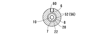
図1ないし図6は、本発明の一実施形態のマイクロバブル発生器1を示しており、図において、マイクロバブル発生器1は、ケース体2と、絞り部3と、気体混合手段4と、気体の斜め導入手段5と、を備えている。そして、気体混合手段4は、気体導入孔6と、環状スリット7と、環状空間8と、を含む。
1 to 6 show a
実施形態のマイクロバブル発生器1は、円筒状のケース体2内にその筒軸100方向に軸心に沿って貫通する主通路10を形成させ、該主通路10の一端側に液体の流入開口10aが設けられるとともに、主通路10の他端側に液体の流出開口10bが設けられている。流入開口10aと流出開口10bとは主通路10で連通されている。ケース体20は、金属またはプラスチック材で形成され液体の圧送に耐え得る強度と剛性を備えている。ケース体20の材質はガラス、セラミックスでもよい。実施形態では成形が容易であり製作コストも安価である点から、プラスチックが用いられている。製品成形は、バルク材からの切削、鋳造、押し出し成形などの方法を用いることができる。
In the
主通路10の長手方向中間位置に通路をオリフィス状に絞る絞り部3が形成されている。図1の実施形態においては、全長L3を例えば1:4強程度に内割り分割する位置に絞り部3が設けられている。絞り部3は、液体の通路を小さくして液体の流れを絞り流速を増加させて第1テーパ部及びその上流側の低速部に比較して最大絞り位置以降の下流側圧力を急激に降下させこの際にマイクロバブルを発生させる。
A
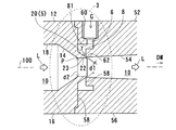
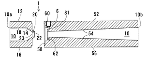
図1において、ケース体2は第1テーパ部14を有する第1ケース部12と、第2テーパ部54を有する第2ケース部52と、をそれぞれ含み、第1、第2ケース部12,52が主通路10の中間位置で直列状に連結されてケース体2を構成する。本実施形態では、図5に示すように第1、第2ケース部12,52はそれぞれ別体の第1、第2半截ケース16、56のそれぞれ端部側を突き合わせ接合してケース体2として一体化させている。このように、第1ケース部12の第1テーパ部14は、流入開口10aから絞り部3に向かってしだいに主通路の内径が小さくなる部位であり、第2ケース部52の第2テーパ部54は、絞り部3から流出開口10bに向けてしだいに主通路の内径が大きくなる部位であり、これらを直列状に組み付けて主通路全体を一体に連通し中間に絞り部3を設けた全体としてベンチュリ管で形成されている。主通路10は断面円形で形成されている。
In FIG. 1, the
第1ケース部12は、第2ケース部52より長さL1が短い円筒形状体からなり、第2ケース部52は、第1ケース部12より長さL2が長い円筒形状体から構成されている。
The
第1ケース部12内の通路は断面平行壁からなる平行部18と、平行部18に連続し絞り部3に向けてしだいに通路径を小さくする第1テーパ部14と、から形成されている。平行部18の一端開口が液体の流入開口10aであり液体が平行部18により平行流として導入され、絞り部3側に向けて圧送される。第1テーパ部14の平行部18から最大絞り位置Pに向かうテーパ角は後述する第2テーパ部54の最大絞り位置Pから流出開口10bに向かうテーパ角度より大きく設定され、急傾斜壁面が形成されている。
The passage in the
第2ケース部52内の通路は絞り部3の一部となる一端58側の通路径が最も小さく形成され、他端の液体の流出開口10bに向けて緩やかな勾配で通路径をしだいに拡大して形成されている。
The passage in the
図1、4に示すように、第1、第2ケース部12、52の接合部分において絞り部3のうちの最大絞り位置Pが設定されている。この最大絞り位置Pを含む絞り部3に気体混合手段4が設けられている。
As shown in FIGS. 1 and 4, the maximum aperture position P of the
図1、4に示すように、第2ケース部52の絞り部3近傍において、第2ケース部のケース体を肉厚方向に貫通して主通路10に連通する気体導入孔6が設けられている。気体導入孔6は最大絞り位置Pよりやや下流側位置のケース体表面側に設けられ例えばねじ切り加工が施された接続ポート60に連通してケース体の肉厚部分を貫通する方向に設けられている。気体導入孔6は、例えば空気、その他のすべてのガスを外部からケース体2の主通路10内に導入させる案内通路であり、好ましくは肉厚方向に直線状に伸びる通路である。主通路10に導入させる気体は送風機等により気体導入孔6に圧送してもよいし、主通路側に自然吸引させてもよい。
As shown in FIGS. 1 and 4, in the vicinity of the narrowed
また、絞り部3の近傍であって気体導入孔6に連通して環状空間8が設けられている。実施形態において、環状空間8は最大絞り位置Pに近接する位置でしかも主通路10に近接する位置において環状に設けられている。すなわち、この環状空間8は断面視で主通路10より外側位置において主通路10を取囲むようにケース体2の構成壁の肉厚部分内に埋め込まれた状態で環状に設けられている。環状空間8は、気体導入孔6からの気体を受け入れて主通路10の外側で環状に取囲むガス溜り部分を形成させ、後述するように環状のスリット7を介して主通路10内に向けて外周側から筒芯側に向かうように環状の隙間から同時に気体を導入させる。実施形態では、この環状空間8は、第1半截ケース16と第2半截ケース56との突合せ衝合部に第1、第2半截ケースのいずれか又は両方に凹部を設けてケース体2の構成壁の肉厚部分内に埋め込み状態で環状に設けられている。そして、気体混合手段4は、気体導入孔6と、環状スリット7と、環状空間8と、を含む。なお、環状スリット7の幅(隙間)d1は、最大絞り位置Pにおける通路内径d2とd1/d2=0.0001〜0.5の比に設定すると多量のマイクロバブルサイズ(例えば50μm以下)の微細気泡を確実に生成させ得ることが実験的に確認されている。なお、より好ましくは、d1/d2=0.001〜0.3の比である。0.0001未満では、気体導入孔6からの気体量が十分でない場合があり、0.5を超えると、均一なサイズのマイクロバブルを得にくい。
An
実施形態において、該環状空間8の断面形状は、横転L字形状であり、入口81にて気体導入孔6と連通する。さらに、本実施形態において、環状空間8は、これに面する断面傾斜状壁20によりその一部が画成されている。断面傾斜状壁20は、環状空間8に面し主通路10内の液体の流れ下流方向DWに下がり傾斜状で設けられ環状スリット7に通じるように形成されている。断面傾斜状壁20は、環状スリット7から主通路10の液体の流れ下流方向DWに下がり傾斜で斜めに向けて気体を導入させる斜め導入手段5を構成する。環状空間8は、図4に示すように、断面視で環状スリット7に向けて連通する空間をしだいに狭める(先細り状)ように設けられている。具体的には、断面傾斜状壁20と第2半截ケース56の通路口縁62部分とが対向した2つの壁により環状スリット7に向けて空間をしだいに狭くして形成されている。環状空間8の断面形状は、横転L字形状に限定されず任意の断面の空間形状としてもよい。
In the embodiment, the cross-sectional shape of the
環状空間8を介して気体導入孔6に連通しかつ主通路10に開放する環状スリット7が環状空間8に連通して設けられている。本実施形態において、環状スリット7は、断面傾斜状壁20の先端が第2ケース部52の通路口縁62側と環状に微小間隙を設けて対向した形態で設けられており、この微小間隙が主通路10に開放することにより形成されている。環状スリット7は、環状空間8の外部からの気体を主通路10の液体の流れ下流方向に下がり傾斜で斜めに向けて気体を導入させる。本実施形態では、環状スリット7は、絞り部3のうちの最大絞り位置P近傍、詳しくは、最大絞り位置Pよりわずかに下流側に設けられており、これによって、液体の流速が最大からわずかに低下してわずかに圧力を上昇させる部分で効果的に気体を吸引し、微細気泡を生成させる。中心を流れる液体中に斜め下がり傾斜状に外側の環状空隙から気体を導入させるから、均等サイズでかつ極めて多くの微細気泡を、生成させることができる。なお、本実施形態では環状スリット7は、円形に連続するスリットで構成されているが、ドット状孔、間欠状孔を円形状に設けたものでも良い。
An
本実施形態において、図5に示すように第1ケース部12の絞り部3となる第1半截ケース16の端面側に環状突起22を形成させている。環状突起22は、第1テーパ部14の端部の最大絞り位置Pから連続し緩やかに径をしだいに大きくする環壁で主通路の一部をなす通路壁23と、第1ケース部本体の端面から連続して環状空間8に面する環壁の断面傾斜状壁20とを表裏対向壁面に有している。実施形態では、環状突起22は、主通路10の液体の流れ下流方向に向けて突出し先鋭形状で設けられている。つまり、環状突起22は一部が主通路10に接するとともに、他部が環状空間8に接して該環状突起22の先端部周囲に環状スリット7を形成する。これによって、内側に圧送される流体が通過し外側は気体が通過することにより環状突起の先端22aは微細に振動を生じさせ、さらに多くの微細気泡生成を促進させることができる。実施形態では、第2ケース部52の絞り部の通路口縁62との間で微小間隙の環状スリット7を形成するように第2ケース部52の絞り部の通路口縁62に環状突起22を近接配置させて環状スリット7が形成されている。したがって、第1ケース部と第2ケース部との接合部において、それらの突合せ衝合状態を利用して主通路10に開放する環状の微小隙間を形成する状態で両ケース部12,52を接合させている。
In the present embodiment, as shown in FIG. 5, an
図6に示すように、第1半截ケース16の接合部端面((a)図参照))は、外周部に位置決め用の周状切欠き64、中央部に主通路10を縁取るように環状突起22、周状切欠き64と環状突起22との中間部の平坦部65とで形成されている。また、第2半截ケース56の接合部端面((b)図参照))は、第1半截ケース16の周状切欠き64と平坦部65に密着衝合する周状突部66と平坦凹部67と、中央部に環状突起22を受け入れて第1半截ケースとの間で環状空間8と、環状スリット7を形成する中央凹部68と、を備えている。
As shown in FIG. 6, the end surface of the joint portion of the first half case 16 (see FIG. 6A) is annular so as to frame the
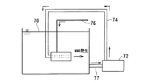
次に、実施形態のマイクロバブル発生器1の作用について説明する。本実施形態のマイクロバブル発生器1は、図7に示すように、例えば処理対象水源70の水中に圧送ポンプ72を圧送管74を介して接続したマイクロバブル発生器1を配置し、気体導入孔6の接続ポート60に気体供給ホース76を接続してホースの先端を大気開放状態に配置させ(あるいはコンプレッサを接続)、水源70の液体を戻し管77によりポンプ72の吸込み側に戻す公知の装置あるいはシステムにおいて用いることができる。この場合、水源70の水は循環処理されるから例えば水の物理的性質を大きく変化させることができる。水の物理的変化として、pHの低下(蒸留水の場合)、表面張力の低下、電気伝導度の上昇などがある。これらの物理的性質が変化した水を使用することで、生体の機能向上、植物や養殖物の収率向上、水質浄化などの効果を奏することができる。これによって、液体を海水あるいは水ないしは淡水とした液体中に空気のマイクロバブルを発生し、水質浄化、水棲生物成長促進機能を行う。液体は特に限定されず、水道水のほか、海水、湖水、薬品類、洗浄液等を使用することができる。腐食性の強い液体を使用する場合には、耐食性の高い材質を用いてケース体を構成するとよい。気体導入孔6から導入する気体は、特に限定されず、空気、酸素、窒素、二酸化炭素、オゾン等の気体を使用することができる。また、気体導入孔には、気体の導入量を制御するための制御弁等を設置し気体流量を制御してもよい。すなわち、液体を有する環境の液体内に本装置を設置して水質浄化等目的で適用することができるばかりか、本装置を用いてバブリング処理した液体を用いて他の適用場面で種々の用途に使用することもできる。
Next, the operation of the
図1において、液体がF方向にマイクロバブル発生器の図上左端側の流入開口10aから流入し、途中の絞り部3を経由して右端側の流出開口10bから出る。流入開口10aから流入した液体は第1テーパ部14部分で通路が急激に狭められ流速を増すとともに圧力を急激に降下させて絞り部3に導入される。最大絞り位置Pで流速は最高となり、この最大絞り位置を通過する絞り部3部分の通路は大きく負圧化する。このとき、最大絞り位置Pより小許液体の流れ下流方向位置の環状スリット7から空気その他のガスで環状に連続したガスが高速で主通路10内に導入され、気液混合流体となる。このとき、環状スリット7から主通路に導入される気体は、通路の外周側から円形に連続する孔から内部に引き込まれるので、十分な量の気体が通路内に供給され、しかも気体が通路内に導入されるときに微小な均等幅のスリット間隙から気体が噴出される結果、液体内で多量の均等サイズのバブルとなる。特に、本実施形態では、環状空間8内の断面傾斜状壁20により環状スリット7から主通路10の液体の流れ下流方向DWに下がり傾斜で斜めに向けて気体を導入させるので、環状空間の円形のサイズを連続的に縮小させながら環状スリットから主通路に導入させる。これにより、主通路10内へ円滑に流れながら円形のサイズを連続的に縮小させつつ気体を液体の通路内に導入するから多数の均等サイズのバブルが生成され、液体内で収縮し確実に良質で多量のマイクロバブルを生成することができる。さらに、本実施形態では、環状突起22が主通路10の液体の流れ下流方向に向けて先鋭形状となっており、内外面を液体及び気体が同時に高速で通過するから、環状突起の先端22aが微細に振動を生じさせる結果、環状スリット7から気体が主通路10内に導入されるときに、液体内で気泡が細かくせん断されやすくなり、これによって、均一でさらに多くの微細気泡生成を促進させることができる。より詳しくは、図8において、本実施形態のマイクロバブル発生器の適用において、液体が水、気体が空気の場合を例にとると、環状スリット7から主通路10の液体Lの流れ下流方向DWに下がり傾斜で斜めに向けて気体Gを導入させることにより、空気が水の流速によって通路内に導入されやすくなり、環状の微小隙間から環状の空気(気体)を高速で主通路の液体内に導入させて円滑に微細気泡MBを発生させる。このとき、空気を内部の断面傾斜状壁20を含む壁面に沿って導入することで、減圧された状態から開放された水が通路口縁62から壁面に広がって空気が一挙にせん断され、微細気泡MBを発生させることができる。また、このとき空気の入口が振動するので、一定の流速になると環状突起22部分が振動し、空気が振動しながら導入されることで水の力によって衝撃波IWが発生しやすくなる。この衝撃波IWは主通路10内で数回起こり、マイクロバブルを含む微細気泡MBの発生を促進する。これによって、発生した気泡は基本的には数と大きさが正規分布にしたがって存在するが、ほとんど均一な40μm程度の大きさを保つことが実験的に確認されている。発生した気泡はほとんどが浮上せず、水中で消滅する。上記の構成のマイクロバブル発生器は、構成される部品点数が少なく、低コストでの製作が可能であり、耐久性も高いものとすることができる。また、第1、第2半截ケースの接合については、接着やねじ込み接合とすることもできる。
In FIG. 1, the liquid flows in the F direction from the
次に、本発明の第2実施形態について、図9により説明するが、第1実施形態と同一部材には同一符号を付し、その詳細な説明は省略する。第2実施形態のマイクロバブル発生器100は、主通路10が断面円形で形成されており、ケース体2の絞り部3近傍位置であり主通路10の直径方向対向位置に対極となる一対の磁力体91,92を配置した点が第1実施形態と異なる。主通路10の直径方向対向位置にN極とS極を有する一対の永久磁石91,92を配置したことにより、液体の表面張力が大きく減少し、マイクロバブルの気液界面張力を減少させて気泡の液体内での収縮を確実にし、溶存酸素濃度を高くして水質改善、水の浄化作用をより強く実効させる。
Next, a second embodiment of the present invention will be described with reference to FIG. 9. The same members as those in the first embodiment are denoted by the same reference numerals, and detailed description thereof will be omitted. In the
図10は、図9の構成によるマイクロバブル発生器を用いてバブリングした際の時間(分)経過における表面張力(dyn/cm)の測定結果を示したものであり、この磁気を用いたマイクロバブル発生器を使うと2時間程度のバブリングで水の表面張力が20dyn/cm程度減少することが確認された。なお、表面張力測定は、デュヌイ表面張力計514−B2型(伊藤製作所製)を用いた。これに比較して磁気を用いないタイプのマイクロバブル発生器は10dyn/cm程度の減少しか示していなかった。なお、本発明のマイクロバブル発生器は、ケース体2の主通路内に周方向の溝、螺旋溝、あるいは液体の流れる方向を制御する旋回翼、等を取りつけて通路内で旋回流を発生させることで、物理的性質を変化させるようにしてもよい。
FIG. 10 shows the measurement results of the surface tension (dyn / cm) over time (minutes) when bubbling using the microbubble generator having the configuration of FIG. 9, and the microbubbles using this magnetism are shown. Using the generator, it was confirmed that the surface tension of water decreased by about 20 dyn / cm after 2 hours of bubbling. In addition, the surface tension measurement used Dunui surface tension meter 514-B2 type (made by Ito Seisakusho). Compared to this, the type of microbubble generator that does not use magnetism showed only a decrease of about 10 dyn / cm. The microbubble generator of the present invention generates a swirl flow in the passage by attaching a circumferential groove, a spiral groove, or a swirl vane for controlling the flow direction of liquid in the main passage of the
本発明のマイクロバブル発生器1は、生理活性作用による植物や養殖物の収率向上、水質浄化、機械装置の洗浄、排水中の界面活性剤除去機能を利用したあらゆる分野においてその適用が考えられる。出願人は、それらの適用について具体的な検証を行った。(1)例えば、水質浄化、水内への豊富な酸素供給量確保機能により、図1実施形態のマイクロバブル発生器と、小形のポンプと空気圧送用コンプレッサとを用いた処理水により淡水魚と海水魚を同一水槽内で生育させ得ることを確認した。(2)また、クルマエビの稚エビ1cm以下25万匹を養殖場に放出し(1)と同様の構成を実施させて99.7%の生存率を確保した。この点、従来の生存率は72%程度であった。また、この際のエアレーションは、通常エアレーション2000dm3に対して約0.1%であり、マイクロバブルの効果を確認した。(3)また、たいらぎ貝について実証実験を行った結果、本装置使用処理水と不使用のものについて6ヶ月経過後の貝のサイズについて本装置使用のものが4倍程度の大きさになることが確認された。(4)さらに本発明のマイクロバブル発生器1による処理水を果物の梨、野菜のナス、トマト、キュウリへの供給、焼酎の製造工程中の酵母製造、大腸菌、サルモネラ菌、黄色ブドウ球菌等の減少確認等の実験を行うことでそれぞれの対照区に対して優れた効果を奏し得ることを確認した。
The
なお、本発明のマイクロバブル発生器は、主通路を液体が通流し、外部から気体導入孔を介して気体を導入してマイクロバブルを発生するようにしているが、主通路に気体を圧送通流させ、外部から液体を負圧導入させると、均等サイズの超微細微粒子を含むミスト気体を生成することができる。 In the microbubble generator of the present invention, liquid flows through the main passage and gas is introduced from the outside through the gas introduction hole to generate microbubbles. When the liquid is flowed and a negative pressure is introduced from the outside, a mist gas containing ultrafine particles of uniform size can be generated.
本発明のマイクロバブル発生器は、上記した実施態様の構成のみに限定されるものではなく、特許請求の範囲に記載した発明の本質を逸脱しない限りにおいて任意に改変してもよい。 The microbubble generator of the present invention is not limited to the configuration of the above-described embodiment, and may be arbitrarily modified without departing from the essence of the invention described in the claims.
1 マイクロバブル発生器
2 ケース体
3 絞り部
4 気体混合手段
5 気体の斜め導入手段
6 気体導入孔
7 環状スリット
8 環状空間
10 主通路
10a 流入開口
10b 流出開口
12 第1ケース部
14 第1テーパ部
16 第1半截ケース
18 平行部
20 断面傾斜状壁
22 環状突起
23 通路壁
52 第2ケース部
54 第2テーパ部
56 第2半截ケース
62 通路口縁
MB 微細気泡
P 最大絞り位置
DW 液体の流れ下流方向
DESCRIPTION OF
本発明は、液体中にマイクロメートルサイズの微細気泡を発生させるマイクロバブル発生器に関する。 The present invention relates to a microbubble generator that generates micrometer-sized fine bubbles in a liquid.
液体中に発生したマイクロメートルオーダーサイズの微細気泡は、気泡体積が微細であるため、例えば直径5ミリメートル以上程度等の通常のサイズの気泡に比して上昇速度が遅く長い間液体中に滞在し続ける、気泡サイズが小さいほど水による表面張力の影響によって気泡内圧が高くなり気体は水中に溶解する、等の特質を有しており、このため、生理活性作用による植物や養殖物の収率向上、水質浄化、機械装置の洗浄、排水中の界面活性剤除去機能を利用して多方面の分野において利用価値を有することが知られるようになっている。このような有用な機能を有するマイクロバブルを液体中に発生させる装置は、液体中で多くの微細気泡を発生させること及び微細気泡発生の確実さを備えたものであることが良い性能を有する条件である。マイクロバブルの発生器については例えば従来、特許文献1、2において提案されたものがある。
Microbubbles of micrometer order size generated in a liquid have a small bubble volume, so that the rising speed is slower than that of a normal size bubble having a diameter of, for example, about 5 mm or more, and stays in the liquid for a long time. Continued, the smaller the bubble size, the higher the internal pressure of the bubble due to the effect of surface tension caused by water, and the gas dissolves in water. In addition, it has become known to have utility value in various fields by utilizing water purification, cleaning of mechanical devices, and the function of removing surfactants in waste water. An apparatus for generating microbubbles having such a useful function in a liquid is a condition that generates a large number of microbubbles in the liquid and has a good performance to have certainty of generating microbubbles. It is. For example, there have been conventionally proposed microbubble generators in
特許文献1のマイクロバブル発生装置は、筒状のケーシング4内に二重筒状に整流筒体6を配置し、ケーシングと整流筒体の間隙に第1プロペラ形翼列7を設置するとともに整流筒体内に第2プロペラ形翼列8を設置し、気体導入ポート17に連通する小孔18によりケーシング内に気体を導入させることにより、気液混合流体を内外逆回りの旋回流としてマイクロバブル発生を促進させるものである。しかしながら、特許文献1の装置では、ケーシングと整流筒体との間、並びに整流筒体内に流体をらせん状に案内する羽根等を設置した構造であり、製造が容易ではなくコスト増となるばかりか気体導入部は小孔18一箇所のみで形成されているのでマイクロバブル発生量が限られ、マイクロバブルに特有の機能を充分に発揮させることができないという問題があった。また、特許文献2は、横長筒体状のケーシングの長手中央をスロート部6とし、一端側にコーン形部5、他端側に末広ノズル部7を形成して流路23で連通したマイクロバブル発生器において、内部に圧送空気の通気路4を設けた進退ロッド8をコーン形部5内に設置してスロート部への進退ロッド先端部の進退動作によりスロート部を通過する液体量を調整しながらマイクロバブルを発生させることを企図したものである。しかしながら、この特許文献2の装置においても気体導入は進退ロッド先端のピンホール42のみにより行なわれるもので、マイクロバブル発生量自体を増加させるものではない。また、文献2の装置は、文献1のものと同様に気泡サイズのばらつきが大きく、ミリサイズ以上の気泡も多く含まれる結果、気泡の多くが大気と接する界面へ上昇し、そのために水中で収縮する気泡の数が少なく水の物理的性質による応用分野での有利な効果を充分に得ることができない、という問題があった。
In the microbubble generator of
本発明は上記従来の課題に鑑みてなされたものであり、その目的は、簡単な構成で低コストで製作でき、また多くの微細気泡を発生させるばかりでなく、マイクロメートルサイズの微細気泡を均一な分布で確実に発生させてマイクロバブルの機能を充分に発揮させることのできるマイクロバブル発生器を提供することにある。 The present invention has been made in view of the above-described conventional problems, and its purpose is to produce a simple structure at a low cost and not only generate a large number of fine bubbles but also uniformly generate micrometer-sized fine bubbles. It is an object of the present invention to provide a microbubble generator that can be reliably generated with a proper distribution and can fully exhibit the function of microbubbles.
上記課題を解決するために本発明は、一端側に設けた液体Lの流入開口10aと他端側に設けた液体の流出開口10bとを主通路10で連通させたケース体2と、主通路10の中間に設けた絞り部3と、絞り部に形成された気体混合手段4と、を含み、気体混合手段は、ケース体2を肉厚方向に貫通して主通路10に連通する気体導入孔6と、絞り部3に配置され気体導入孔6に連通するとともに主通路10に開放する環状スリット7と、気体導入孔6に連通するとともに環状スリット7に連通する環状空間8と、を備え、環状空間8からの気体であって、環状スリット7から主通路10の液体の流れ下流方向DWに斜めに向けて気体Gを導入させる斜め導入手段5を設け、斜め導入手段5は、環状空間8に面し主通路10の液体の流れ下流方向DWに下がり傾斜状で設けられ環状スリット7に通じる断面傾斜状壁20を含み、環状スリット7は、絞り部3のうちの最大絞り位置P近傍で最大絞り位置よりも下流側に設けられたマイクロバブル発生器1から構成される。
In order to solve the above problems, the present invention provides a
その際、絞り部3は、一部が主通路10に接するとともに他部が環状空間8に接し先端部周囲に環状スリット7を形成する環状突起であり、主通路10の液体の流れ下流方向DWに突出する環状突起22を含むとよい。
At that time, the
また、環状突起22は、主通路10の液体の流れ下流方向に向けて先鋭形状とするとなおよい。
Further, it is more preferable that the
また、本発明のマイクロバブル発生器は、絞り部3に向けて通路径をしだいに径小とした第1テーパ部14を有する第1ケース部12と、絞り部3から通路径をしだいに径大とした第2テーパ部54を有する第2ケース部52と、を接合してケース体2が構成され、第1ケース部12の絞り部3に環状突起22を形成させ、第2ケース部52の絞り部の通路口縁62との間で微小間隙の環状スリット7を形成するように第2ケース部52の絞り部の主通路入口(62)に環状突起 22を近接配置させるとよい。
In addition, the microbubble generator of the present invention includes a
その際、第1ケース部12と第2ケース部52との接合部において、第2ケース部52に環状突起22を近接配置させる際に該環状突起の外周側に気体導入孔6と環状スリット7に連通する環状空間8を設けるとよい。
At this time, when the
また、主通路10は断面円形で形成されており、ケース体2の絞り部3近傍位置であり主通路10の直径方向対向位置に対極となる一対の磁力体を配置してもよい。
Further, the
本発明のマイクロバブル発生器によれば、一端側に設けた液体の流入開口と他端側に設けた液体の流出開口とを主通路で連通させたケース体と、主通路の中間に設けた絞り部と、絞り部に形成された気体混合手段と、を含み、気体混合手段は、ケース体を肉厚方向に貫通して主通路に連通する気体導入孔と、絞り部に配置され気体導入孔に連通するとともに主通路に開放する環状スリットと、気体導入孔に連通するとともに環状スリットに連通する環状空間と、を備え、環状空間からの気体であって、環状スリットから主通路の液体の流れ下流方向に斜めに向けて気体を導入させる斜め導入手段を設けた構成であるから、簡単な構成で低コストで製作でき、また多くの微細気泡を発生させるばかりでなく、マイクロメートルサイズの微細気泡を均一な分布で確実に発生させてマイクロバブルの機能を充分に発揮させることができる。特に、気体の斜め導入手段により環状スリットから主通路の液体の流れ下流方向に斜めに向けて気体を導入させるので、通路内への導入時に妨げるものがなく主通路内への円滑な流れで気体を液体の通路内に導入して多数の均等サイズのマイクロバブルを確実に生成することができる。 According to the microbubble generator of the present invention, the case body in which the liquid inflow opening provided on one end side and the liquid outflow opening provided on the other end side are communicated with each other through the main passage, and provided in the middle of the main passage. The gas mixing means includes a throttle portion and a gas mixing means formed in the throttle portion, and the gas mixing means is arranged in the throttle portion so as to pass through the case body in the thickness direction and communicate with the main passage. An annular slit that communicates with the hole and opens to the main passage; and an annular space that communicates with the gas introduction hole and communicates with the annular slit, the gas from the annular space, and the liquid in the main passage from the annular slit. Since it has a configuration that includes an oblique introduction means that introduces gas in a direction downstream of the flow, it can be manufactured at a low cost with a simple configuration, and not only generates many fine bubbles but also a micrometer-sized micro Bubbles Reliably generate a uniform distribution can be sufficiently exhibit the function of the micro-bubble. In particular, since the gas is introduced obliquely in the downstream direction of the liquid flow of the main passage from the annular slit by the gas oblique introduction means, there is no hindrance when introduced into the passage, and the gas flows smoothly into the main passage. Can be introduced into the liquid passage to reliably generate a large number of equally sized microbubbles.
また、斜め導入手段は、環状空間に面し主通路の液体の流れ下流方向に下がり傾斜状で設けられ環状スリットに通じる断面傾斜状壁を含む構成であるから、第1ケース部等を用いて環状空間に面する断面傾斜状壁を形成でき、主通路内への円滑な流れで気体を液体の通路内に導入して多数の均等サイズのマイクロバブルの確実な生成を実効化することができる。 In addition, the oblique introduction means is configured to include an inclined wall that faces the annular space and is provided in an inclined manner in the downstream direction of the liquid flow of the main passage and communicates with the annular slit. An inclined wall facing the annular space can be formed, and gas can be introduced into the liquid passage with a smooth flow into the main passage to effectively produce a large number of equally sized microbubbles. .
また、環状スリットは、絞り部のうちの最大絞り位置近傍で最大絞り位置よりも下流側に設けられた構成であるから、2つの半截ケースの接合などを利用して埋め込み状の環状空間と斜め導入手段と環状スリットを有する特殊な構成をベンチュリ管の絞り部において同時に実現することができる。 Further, the annular slit is provided in the vicinity of the maximum throttle position in the throttle portion and on the downstream side of the maximum throttle position. A special configuration having an introduction means and an annular slit can be realized simultaneously in the throttle part of the venturi tube.
また、絞り部は、一部が主通路に接するとともに他部が環状空間に接し先端部周囲に環状スリットを形成する環状突起であり、主通路の液体の流れ下流方向に突出する環状突起を含む構成であるから、気体の斜め導入手段と環状空間の形成とを具体的に実現することができる。 Further, the throttle portion is an annular protrusion that is partly in contact with the main passage and the other portion is in contact with the annular space and forms an annular slit around the tip, and includes an annular protrusion that protrudes in the downstream direction of the liquid flow in the main passage. Because of the configuration, it is possible to specifically realize the oblique gas introduction means and the formation of the annular space.
また、環状突起は、主通路の液体の流れ下流方向に向けて先鋭形状となっている構成とすることにより、気体の斜め導入手段と環状空間の形成とを実現し、主通路と気体導入用の環状空間側の表裏面に異なる相を通流させて微小振動を生じさせ、マイクロバブル生成を促進させることができる。 In addition, the annular protrusion is configured to have a sharpened shape toward the downstream direction of the liquid flow in the main passage, thereby realizing oblique gas introduction means and formation of an annular space. It is possible to cause micro vibrations by flowing different phases through the front and back surfaces of the annular space, thereby promoting the generation of microbubbles.
また、絞り部に向けて通路径をしだいに径小とした第1テーパ部を有する第1ケース部と、絞り部から通路径をしだいに径大とした第2テーパ部を有する第2ケース部と、を接合してケース体が構成され、第1ケース部の絞り部に環状突起を形成させ、第2ケース部の絞り部の通路口縁との間で微小間隙の環状スリットを形成するように第2ケース部の絞り部の主通路入口に環状突起を近接配置させた構成とすることにより、第1、第1ケース部の2つのパーツの接合部を利用して具体的に埋め込み状の環状空間、断面傾斜状壁、環状スリットを形成することができる。 Also, a first case portion having a first taper portion whose diameter is gradually reduced toward the throttle portion, and a second case portion having a second taper portion whose diameter is gradually increased from the throttle portion. To form a ring-shaped protrusion on the throttle portion of the first case portion, and to form an annular slit with a minute gap between the passage opening edge of the throttle portion of the second case portion. By adopting a configuration in which an annular protrusion is arranged close to the main passage inlet of the throttle part of the second case part, the joint part of the two parts of the first and first case parts is specifically used in the embedded shape. An annular space, a cross-sectionally inclined wall, and an annular slit can be formed.
また、第1ケース部と第2ケース部との接合部において、第2ケース部に環状突起を近接配置させる際に該環状突起の外周側に気体導入孔と環状スリットに連通する環状空間を設けた構成であるから、主通路の外周側から環状スリットを介して斜め下流側に向けて円形状の気体を導入させることができる。 In addition, an annular space communicating with the gas introduction hole and the annular slit is provided on the outer peripheral side of the annular protrusion when the annular protrusion is disposed close to the second case part at the joint between the first case part and the second case part. Therefore, a circular gas can be introduced from the outer peripheral side of the main passage toward the obliquely downstream side through the annular slit.
また、主通路は断面円形で形成されており、ケース体の絞り部近傍位置であり主通路の直径方向対向位置に対極となる一対の磁力体を配置した構成とすることにより、例えば水などの液体の表面張力を小さくし、マイクロバブルの気液界面張力を減少させて気泡の液体内での収縮を確実にし、溶存酸素濃度を高くして水質改善、水の浄化作用をより強く実効化させることができる。 In addition, the main passage is formed in a circular shape in cross section, and has a configuration in which a pair of magnetic bodies as counter electrodes are arranged at positions near the throttle portion of the case body and in the diameter direction of the main passage. Reduce the surface tension of the liquid, reduce the gas-liquid interfacial tension of the microbubbles to ensure the contraction of the bubbles in the liquid, increase the dissolved oxygen concentration to improve the water quality and make the water purification effect more effective. be able to.
次に、本発明の実施形態に係るマイクロバブル発生器について図1〜図6を参照して説明する。本発明のマイクロバブル発生器は、ケース体内の通路に液体を圧送し同時にその液体の流れの中に気体を導入させてマイクロバブルを発生させる装置であり、通路内に液体を圧送しつつ外部から気体を導入させて気液混合流体を生成し、数十ミクロン程度の径の多量のマイクロバブルを均質分布で含む流体を生成させる。ここに、マイクロバブルとは、数十ミクロン以下のサイズのバブル、具体的には、50μm〜1μmサイズの気泡を言う。 Next, the microbubble generator which concerns on embodiment of this invention is demonstrated with reference to FIGS. The microbubble generator of the present invention is a device for generating a microbubble by pumping a liquid into a passage in the case body and simultaneously introducing a gas into the flow of the liquid. A gas-liquid mixed fluid is generated by introducing gas, and a fluid containing a large number of microbubbles with a diameter of about several tens of microns in a homogeneous distribution is generated. Here, the microbubble refers to a bubble having a size of several tens of microns or less, specifically, a bubble having a size of 50 μm to 1 μm.
図1ないし図6は、本発明の一実施形態のマイクロバブル発生器1を示しており、図において、マイクロバブル発生器1は、ケース体2と、絞り部3と、気体混合手段4と、気体の斜め導入手段5と、を備えている。そして、気体混合手段4は、気体導入孔6と、環状スリット7と、環状空間8と、を含む。
1 to 6 show a
実施形態のマイクロバブル発生器1は、円筒状のケース体2内にその筒軸100方向に軸心に沿って貫通する主通路10を形成させ、該主通路10の一端側に液体の流入開口10aが設けられるとともに、主通路10の他端側に液体の流出開口10bが設けられている。流入開口10aと流出開口10bとは主通路10で連通されている。ケース体20は、金属またはプラスチック材で形成され液体の圧送に耐え得る強度と剛性を備えている。ケース体20の材質はガラス、セラミックスでもよい。実施形態では成形が容易であり製作コストも安価である点から、プラスチックが用いられている。製品成形は、バルク材からの切削、鋳造、押し出し成形などの方法を用いることができる。
In the
主通路10の長手方向中間位置に通路をオリフィス状に絞る絞り部3が形成されている。図1の実施形態においては、全長L3を例えば1:4強程度に内割り分割する位置に絞り部3が設けられている。絞り部3は、液体の通路を小さくして液体の流れを絞り流速を増加させて第1テーパ部及びその上流側の低速部に比較して最大絞り位置以降の下流側圧力を急激に降下させこの際にマイクロバブルを発生させる。
A
図1において、ケース体2は第1テーパ部14を有する第1ケース部12と、第2テーパ部54を有する第2ケース部52と、をそれぞれ含み、第1、第2ケース部12,52が主通路10の中間位置で直列状に連結されてケース体2を構成する。本実施形態では、図5に示すように第1、第2ケース部12,52はそれぞれ別体の第1、第2半截ケース16、56のそれぞれ端部側を突き合わせ接合してケース体2として一体化させている。このように、第1ケース部12の第1テーパ部14は、流入開口10aから絞り部3に向かってしだいに主通路の内径が小さくなる部位であり、第2ケース部52の第2テーパ部54は、絞り部3から流出開口10bに向けてしだいに主通路の内径が大きくなる部位であり、これらを直列状に組み付けて主通路全体を一体に連通し中間に絞り部3を設けた全体としてベンチュリ管で形成されている。主通路10は断面円形で形成されている。
In FIG. 1, the
第1ケース部12は、第2ケース部52より長さL1が短い円筒形状体からなり、第2ケース部52は、第1ケース部12より長さL2が長い円筒形状体から構成されている。
The
第1ケース部12内の通路は断面平行壁からなる平行部18と、平行部18に連続し絞り部3に向けてしだいに通路径を小さくする第1テーパ部14と、から形成されている。平行部18の一端開口が液体の流入開口10aであり液体が平行部18により平行流として導入され、絞り部3側に向けて圧送される。第1テーパ部14の平行部18から最大絞り位置Pに向かうテーパ角は後述する第2テーパ部54の最大絞り位置Pから流出開口10bに向かうテーパ角度より大きく設定され、急傾斜壁面が形成されている。
The passage in the
第2ケース部52内の通路は絞り部3の一部となる一端58側の通路径が最も小さく形成され、他端の液体の流出開口10bに向けて緩やかな勾配で通路径をしだいに拡大して形成されている。
The passage in the
図1、4に示すように、第1、第2ケース部12、52の接合部分において絞り部3のうちの最大絞り位置Pが設定されている。この最大絞り位置Pを含む絞り部3に気体混合手段4が設けられている。
As shown in FIGS. 1 and 4, the maximum aperture position P of the
図1、4に示すように、第2ケース部52の絞り部3近傍において、第2ケース部のケース体を肉厚方向に貫通して主通路10に連通する気体導入孔6が設けられている。気体導入孔6は最大絞り位置Pよりやや下流側位置のケース体表面側に設けられ例えばねじ切り加工が施された接続ポート60に連通してケース体の肉厚部分を貫通する方向に設けられている。気体導入孔6は、例えば空気、その他のすべてのガスを外部からケース体2の主通路10内に導入させる案内通路であり、好ましくは肉厚方向に直線状に伸びる通路である。主通路10に導入させる気体は送風機等により気体導入孔6に圧送してもよいし、主通路側に自然吸引させてもよい。
As shown in FIGS. 1 and 4, in the vicinity of the narrowed
また、絞り部3の近傍であって気体導入孔6に連通して環状空間8が設けられている。実施形態において、環状空間8は最大絞り位置Pに近接する位置でしかも主通路10に近接する位置において環状に設けられている。すなわち、この環状空間8は断面視で主通路10より外側位置において主通路10を取囲むようにケース体2の構成壁の肉厚部分内に埋め込まれた状態で環状に設けられている。環状空間8は、気体導入孔6からの気体を受け入れて主通路10の外側で環状に取囲むガス溜り部分を形成させ、後述するように環状のスリット7を介して主通路10内に向けて外周側から筒芯側に向かうように環状の隙間から同時に気体を導入させる。実施形態では、この環状空間8は、第1半截ケース16と第2半截ケース56との突合せ衝合部に第1、第2半截ケースのいずれか又は両方に凹部を設けてケース体2の構成壁の肉厚部分内に埋め込み状態で環状に設けられている。そして、気体混合手段4は、気体導入孔6と、環状スリット7と、環状空間8と、を含む。なお、環状スリット7の幅(隙間)d1は、最大絞り位置Pにおける通路内径d2とd1/d2=0.0001〜0.5の比に設定すると多量のマイクロバブルサイズ(例えば50μm以下)の微細気泡を確実に生成させ得ることが実験的に確認されている。なお、より好ましくは、d1/d2=0.001〜0.3の比である。0.0001未満では、気体導入孔6からの気体量が十分でない場合があり、0.5を超えると、均一なサイズのマイクロバブルを得にくい。
An
実施形態において、該環状空間8の断面形状は、横転L字形状であり、入口81にて気体導入孔6と連通する。さらに、本実施形態において、環状空間8は、これに面する断面傾斜状壁20によりその一部が画成されている。断面傾斜状壁20は、環状空間8に面し主通路10内の液体の流れ下流方向DWに下がり傾斜状で設けられ環状スリット7に通じるように形成されている。断面傾斜状壁20は、環状スリット7から主通路10の液体の流れ下流方向DWに下がり傾斜で斜めに向けて気体を導入させる斜め導入手段5を構成する。環状空間8は、図4に示すように、断面視で環状スリット7に向けて連通する空間をしだいに狭める(先細り状)ように設けられている。具体的には、断面傾斜状壁20と第2半截ケース56の通路口縁62部分とが対向した2つの壁により環状スリット7に向けて空間をしだいに狭くして形成されている。環状空間8の断面形状は、横転L字形状に限定されず任意の断面の空間形状としてもよい。
In the embodiment, the cross-sectional shape of the
環状空間8を介して気体導入孔6に連通しかつ主通路10に開放する環状スリット7が環状空間8に連通して設けられている。本実施形態において、環状スリット7は、断面傾斜状壁20の先端が第2ケース部52の通路口縁62側と環状に微小間隙を設けて対向した形態で設けられており、この微小間隙が主通路10に開放することにより形成されている。環状スリット7は、環状空間8の外部からの気体を主通路10の液体の流れ下流方向に下がり傾斜で斜めに向けて気体を導入させる。本実施形態では、環状スリット7は、絞り部3のうちの最大絞り位置P近傍、詳しくは、最大絞り位置Pよりわずかに下流側に設けられており、これによって、液体の流速が最大からわずかに低下してわずかに圧力を上昇させる部分で効果的に気体を吸引し、微細気泡を生成させる。中心を流れる液体中に斜め下がり傾斜状に外側の環状空隙から気体を導入させるから、均等サイズでかつ極めて多くの微細気泡を、生成させることができる。なお、本実施形態では環状スリット7は、円形に連続するスリットで構成されているが、ドット状孔、間欠状孔を円形状に設けたものでも良い。
An
本実施形態において、図5に示すように第1ケース部12の絞り部3となる第1半截ケース16の端面側に環状突起22を形成させている。環状突起22は、第1テーパ部14の端部の最大絞り位置Pから連続し緩やかに径をしだいに大きくする環壁で主通路の一部をなす通路壁23と、第1ケース部本体の端面から連続して環状空間8に面する環壁の断面傾斜状壁20とを表裏対向壁面に有している。実施形態では、環状突起22は、主通路10の液体の流れ下流方向に向けて突出し先鋭形状で設けられている。つまり、環状突起22は一部が主通路10に接するとともに、他部が環状空間8に接して該環状突起22の先端部周囲に環状スリット7を形成する。これによって、内側に圧送される流体が通過し外側は気体が通過することにより環状突起の先端22aは微細に振動を生じさせ、さらに多くの微細気泡生成を促進させることができる。実施形態では、第2ケース部52の絞り部の通路口縁62との間で微小間隙の環状スリット7を形成するように第2ケース部52の絞り部の通路口縁62に環状突起22を近接配置させて環状スリット7が形成されている。したがって、第1ケース部と第2ケース部との接合部において、それらの突合せ衝合状態を利用して主通路10に開放する環状の微小隙間を形成する状態で両ケース部12,52を接合させている。
In the present embodiment, as shown in FIG. 5, an
図6に示すように、第1半截ケース16の接合部端面((a)図参照))は、外周部に位置決め用の周状切欠き64、中央部に主通路10を縁取るように環状突起22、周状切欠き64と環状突起22との中間部の平坦部65とで形成されている。また、第2半截ケース56の接合部端面((b)図参照))は、第1半截ケース16の周状切欠き64と平坦部65に密着衝合する周状突部66と平坦凹部67と、中央部に環状突起22を受け入れて第1半截ケースとの間で環状空間8と、環状スリット7を形成する中央凹部68と、を備えている。
As shown in FIG. 6, the end surface of the joint portion of the first half case 16 (see FIG. 6A) is annular so as to frame the
次に、実施形態のマイクロバブル発生器1の作用について説明する。本実施形態のマイクロバブル発生器1は、図7に示すように、例えば処理対象水源70の水中に圧送ポンプ72を圧送管74を介して接続したマイクロバブル発生器1を配置し、気体導入孔6の接続ポート60に気体供給ホース76を接続してホースの先端を大気開放状態に配置させ(あるいはコンプレッサを接続)、水源70の液体を戻し管77によりポンプ72の吸込み側に戻す公知の装置あるいはシステムにおいて用いることができる。この場合、水源70の水は循環処理されるから例えば水の物理的性質を大きく変化させることができる。水の物理的変化として、pHの低下(蒸留水の場合)、表面張力の低下、電気伝導度の上昇などがある。これらの物理的性質が変化した水を使用することで、生体の機能向上、植物や養殖物の収率向上、水質浄化などの効果を奏することができる。これによって、液体を海水あるいは水ないしは淡水とした液体中に空気のマイクロバブルを発生し、水質浄化、水棲生物成長促進機能を行う。液体は特に限定されず、水道水のほか、海水、湖水、薬品類、洗浄液等を使用することができる。腐食性の強い液体を使用する場合には、耐食性の高い材質を用いてケース体を構成するとよい。気体導入孔6から導入する気体は、特に限定されず、空気、酸素、窒素、二酸化炭素、オゾン等の気体を使用することができる。また、気体導入孔には、気体の導入量を制御するための制御弁等を設置し気体流量を制御してもよい。すなわち、液体を有する環境の液体内に本装置を設置して水質浄化等目的で適用することができるばかりか、本装置を用いてバブリング処理した液体を用いて他の適用場面で種々の用途に使用することもできる。
Next, the operation of the
図1において、液体がF方向にマイクロバブル発生器の図上左端側の流入開口10aから流入し、途中の絞り部3を経由して右端側の流出開口10bから出る。流入開口10aから流入した液体は第1テーパ部14部分で通路が急激に狭められ流速を増すとともに圧力を急激に降下させて絞り部3に導入される。最大絞り位置Pで流速は最高となり、この最大絞り位置を通過する絞り部3部分の通路は大きく負圧化する。このとき、最大絞り位置Pより小許液体の流れ下流方向位置の環状スリット7から空気その他のガスで環状に連続したガスが高速で主通路10内に導入され、気液混合流体となる。このとき、環状スリット7から主通路に導入される気体は、通路の外周側から円形に連続する孔から内部に引き込まれるので、十分な量の気体が通路内に供給され、しかも気体が通路内に導入されるときに微小な均等幅のスリット間隙から気体が噴出される結果、液体内で多量の均等サイズのバブルとなる。特に、本実施形態では、環状空間8内の断面傾斜状壁20により環状スリット7から主通路10の液体の流れ下流方向DWに下がり傾斜で斜めに向けて気体を導入させるので、環状空間の円形のサイズを連続的に縮小させながら環状スリットから主通路に導入させる。これにより、主通路10内へ円滑に流れながら円形のサイズを連続的に縮小させつつ気体を液体の通路内に導入するから多数の均等サイズのバブルが生成され、液体内で収縮し確実に良質で多量のマイクロバブルを生成することができる。さらに、本実施形態では、環状突起22が主通路10の液体の流れ下流方向に向けて先鋭形状となっており、内外面を液体及び気体が同時に高速で通過するから、環状突起の先端22aが微細に振動を生じさせる結果、環状スリット7から気体が主通路10内に導入されるときに、液体内で気泡が細かくせん断されやすくなり、これによって、均一でさらに多くの微細気泡生成を促進させることができる。より詳しくは、図8において、本実施形態のマイクロバブル発生器の適用において、液体が水、気体が空気の場合を例にとると、環状スリット7から主通路10の液体Lの流れ下流方向DWに下がり傾斜で斜めに向けて気体Gを導入させることにより、空気が水の流速によって通路内に導入されやすくなり、環状の微小隙間から環状の空気(気体)を高速で主通路の液体内に導入させて円滑に微細気泡MBを発生させる。このとき、空気を内部の断面傾斜状壁20を含む壁面に沿って導入することで、減圧された状態から開放された水が通路口縁62から壁面に広がって空気が一挙にせん断され、微細気泡MBを発生させることができる。また、このとき空気の入口が振動するので、一定の流速になると環状突起22部分が振動し、空気が振動しながら導入されることで水の力によって衝撃波IWが発生しやすくなる。この衝撃波IWは主通路10内で数回起こり、マイクロバブルを含む微細気泡MBの発生を促進する。これによって、発生した気泡は基本的には数と大きさが正規分布にしたがって存在するが、ほとんど均一な40μm程度の大きさを保つことが実験的に確認されている。発生した気泡はほとんどが浮上せず、水中で消滅する。上記の構成のマイクロバブル発生器は、構成される部品点数が少なく、低コストでの製作が可能であり、耐久性も高いものとすることができる。また、第1、第2半截ケースの接合については、接着やねじ込み接合とすることもできる。
In FIG. 1, the liquid flows in the F direction from the
次に、本発明の第2実施形態について、図9により説明するが、第1実施形態と同一部材には同一符号を付し、その詳細な説明は省略する。第2実施形態のマイクロバブル発生器100は、主通路10が断面円形で形成されており、ケース体2の絞り部3近傍位置であり主通路10の直径方向対向位置に対極となる一対の磁力体91,92を配置した点が第1実施形態と異なる。主通路10の直径方向対向位置にN極とS極を有する一対の永久磁石91,92を配置したことにより、液体の表面張力が大きく減少し、マイクロバブルの気液界面張力を減少させて気泡の液体内での収縮を確実にし、溶存酸素濃度を高くして水質改善、水の浄化作用をより強く実効させる。
Next, a second embodiment of the present invention will be described with reference to FIG. 9. The same members as those in the first embodiment are denoted by the same reference numerals, and detailed description thereof will be omitted. In the
図10は、図9の構成によるマイクロバブル発生器を用いてバブリングした際の時間(分)経過における表面張力(dyn/cm)の測定結果を示したものであり、この磁気を用いたマイクロバブル発生器を使うと2時間程度のバブリングで水の表面張力が20dyn/cm程度減少することが確認された。なお、表面張力測定は、デュヌイ表面張力計514−B2型(伊藤製作所製)を用いた。これに比較して磁気を用いないタイプのマイクロバブル発生器は10dyn/cm程度の減少しか示していなかった。なお、本発明のマイクロバブル発生器は、ケース体2の主通路内に周方向の溝、螺旋溝、あるいは液体の流れる方向を制御する旋回翼、等を取りつけて通路内で旋回流を発生させることで、物理的性質を変化させるようにしてもよい。
FIG. 10 shows the measurement results of the surface tension (dyn / cm) over time (minutes) when bubbling using the microbubble generator having the configuration of FIG. 9, and the microbubbles using this magnetism are shown. Using the generator, it was confirmed that the surface tension of water decreased by about 20 dyn / cm after 2 hours of bubbling. In addition, the surface tension measurement used Dunui surface tension meter 514-B2 type (made by Ito Seisakusho). Compared to this, the type of microbubble generator that does not use magnetism showed only a decrease of about 10 dyn / cm. The microbubble generator of the present invention generates a swirl flow in the passage by attaching a circumferential groove, a spiral groove, or a swirl vane for controlling the flow direction of liquid in the main passage of the
本発明のマイクロバブル発生器1は、生理活性作用による植物や養殖物の収率向上、水質浄化、機械装置の洗浄、排水中の界面活性剤除去機能を利用したあらゆる分野においてその適用が考えられる。出願人は、それらの適用について具体的な検証を行った。(1)例えば、水質浄化、水内への豊富な酸素供給量確保機能により、図1実施形態のマイクロバブル発生器と、小形のポンプと空気圧送用コンプレッサとを用いた処理水により淡水魚と海水魚を同一水槽内で生育させ得ることを確認した。(2)また、クルマエビの稚エビ1cm以下25万匹を養殖場に放出し(1)と同様の構成を実施させて99.7%の生存率を確保した。この点、従来の生存率は72%程度であった。また、この際のエアレーションは、通常エアレーション2000dm3に対して約0.1%であり、マイクロバブルの効果を確認した。(3)また、たいらぎ貝について実証実験を行った結果、本装置使用処理水と不使用のものについて6ヶ月経過後の貝のサイズについて本装置使用のものが4倍程度の大きさになることが確認された。(4)さらに本発明のマイクロバブル発生器1による処理水を果物の梨、野菜のナス、トマト、キュウリへの供給、焼酎の製造工程中の酵母製造、大腸菌、サルモネラ菌、黄色ブドウ球菌等の減少確認等の実験を行うことでそれぞれの対照区に対して優れた効果を奏し得ることを確認した。
The
なお、本発明のマイクロバブル発生器は、主通路を液体が通流し、外部から気体導入孔を介して気体を導入してマイクロバブルを発生するようにしているが、主通路に気体を圧送通流させ、外部から液体を負圧導入させると、均等サイズの超微細微粒子を含むミスト気体を生成することができる。 In the microbubble generator of the present invention, liquid flows through the main passage and gas is introduced from the outside through the gas introduction hole to generate microbubbles. When the liquid is flowed and a negative pressure is introduced from the outside, a mist gas containing ultrafine particles of uniform size can be generated.
本発明のマイクロバブル発生器は、上記した実施態様の構成のみに限定されるものではなく、特許請求の範囲に記載した発明の本質を逸脱しない限りにおいて任意に改変してもよい。 The microbubble generator of the present invention is not limited to the configuration of the above-described embodiment, and may be arbitrarily modified without departing from the essence of the invention described in the claims.
1 マイクロバブル発生器
2 ケース体
3 絞り部
4 気体混合手段
5 気体の斜め導入手段
6 気体導入孔
7 環状スリット
8 環状空間
10 主通路
10a 流入開口
10b 流出開口
12 第1ケース部
14 第1テーパ部
16 第1半截ケース
18 平行部
20 断面傾斜状壁
22 環状突起
23 通路壁
52 第2ケース部
54 第2テーパ部
56 第2半截ケース
62 通路口縁
MB 微細気泡
P 最大絞り位置
DW 液体の流れ下流方向
DESCRIPTION OF
Claims (8)
主通路の中間に設けた絞り部と、
絞り部に形成された気体混合手段と、を含み、
気体混合手段は、ケース体を肉厚方向に貫通して主通路に連通する気体導入孔と、絞り部に配置され気体導入孔に連通するとともに主通路に開放する環状スリットと、気体導入孔に連通するとともに環状スリットに連通する環状空間と、を備え、
環状空間からの気体であって、環状スリットから主通路の液体の流れ下流方向に斜めに向けて気体を導入させる斜め導入手段を設けたことを特徴とするマイクロバブル発生器。 A case body in which a liquid inflow opening provided on one end side and a liquid outflow opening provided on the other end side communicate with each other through a main passage;
A throttle part provided in the middle of the main passage;
Gas mixing means formed in the throttle part,
The gas mixing means includes a gas introduction hole that penetrates the case body in the thickness direction and communicates with the main passage, an annular slit that is disposed in the throttle portion and communicates with the gas introduction hole and opens to the main passage, and a gas introduction hole. And an annular space that communicates with the annular slit,
A microbubble generator characterized in that it is provided with oblique introduction means for introducing gas from an annular space obliquely toward the downstream of the liquid flow in the main passage from the annular slit.
第1ケース部の絞り部に環状突起を形成させ、第2ケース部の絞り部の通路口縁との間で微小間隙の環状スリットを形成するように第2ケース部の絞り部の主通路入口に環状突起を近接配置させたことを特徴とする請求項1ないし5のいずれかに記載のマイクロバブル発生器。 A first case portion having a first taper portion whose diameter is gradually reduced toward the throttle portion; a second case portion having a second taper portion whose diameter is gradually increased from the throttle portion; To form a case body,
An annular protrusion is formed on the throttle portion of the first case portion, and an annular slit with a minute gap is formed between the passage opening edge of the throttle portion of the second case portion and the main passage inlet of the throttle portion of the second case portion. 6. A microbubble generator according to any one of claims 1 to 5, wherein annular projections are arranged close to each other.
The main passage is formed in a circular cross section, and a pair of magnetic bodies as counter electrodes are arranged at positions near the throttle portion of the case body and in the diameter direction of the main passage. The microbubble generator according to crab.
Priority Applications (1)
| Application Number | Priority Date | Filing Date | Title |
|---|---|---|---|
| JP2011039274A JP5257819B2 (en) | 2011-02-25 | 2011-02-25 | Micro bubble generator |
Applications Claiming Priority (1)
| Application Number | Priority Date | Filing Date | Title |
|---|---|---|---|
| JP2011039274A JP5257819B2 (en) | 2011-02-25 | 2011-02-25 | Micro bubble generator |
Publications (2)
| Publication Number | Publication Date |
|---|---|
| JP2012176335A true JP2012176335A (en) | 2012-09-13 |
| JP5257819B2 JP5257819B2 (en) | 2013-08-07 |
Family
ID=46978593
Family Applications (1)
| Application Number | Title | Priority Date | Filing Date |
|---|---|---|---|
| JP2011039274A Active JP5257819B2 (en) | 2011-02-25 | 2011-02-25 | Micro bubble generator |
Country Status (1)
| Country | Link |
|---|---|
| JP (1) | JP5257819B2 (en) |
Cited By (10)
| Publication number | Priority date | Publication date | Assignee | Title |
|---|---|---|---|---|
| JP2015047527A (en) * | 2013-08-30 | 2015-03-16 | 株式会社デンソー | Ejector device and pipe washing device |
| WO2015064159A1 (en) * | 2013-10-31 | 2015-05-07 | 日之出産業株式会社 | Microbubble formation method, and microbubble formation device |
| JP2015093219A (en) * | 2013-11-11 | 2015-05-18 | スプレーイングシステムスジャパン株式会社 | Microbubble generation device and microbubble spray device |
| JP2017131809A (en) * | 2016-01-26 | 2017-08-03 | 株式会社エーワンテクニカ | Nozzle for generating nano-bubble, nano-bubble generating system, and nano-bubble generating method |
| JP2019122904A (en) * | 2018-01-15 | 2019-07-25 | 株式会社三進製作所 | Microbubble generating tool and microbubble generator |
| CN110292021A (en) * | 2019-08-03 | 2019-10-01 | 盐城师范学院 | Beach aquaculture pond automatic water-replacing and oxygen-increasing device |
| JPWO2019189812A1 (en) * | 2018-03-30 | 2020-04-30 | 三菱ケミカルエンジニアリング株式会社 | Fine bubble generating nozzle, method for mixing bubbles containing fine bubbles in liquid using the fine bubble generating nozzle, bioreactor equipped with the fine bubble generating nozzle, and a plurality of fine bubble generating nozzles A nozzle device for generating fine bubbles |
| WO2021229398A3 (en) * | 2020-05-12 | 2021-12-23 | Nir Oz | Micro/nano bubble generator and/or system |
| WO2022005222A1 (en) * | 2020-07-02 | 2022-01-06 | 주식회사에이디수산 | Air-lifting venturi device |
| JP7329397B2 (en) | 2019-09-12 | 2023-08-18 | リンナイ株式会社 | Fine bubble generating nozzle body |
Families Citing this family (1)
| Publication number | Priority date | Publication date | Assignee | Title |
|---|---|---|---|---|
| JP6169749B1 (en) * | 2016-04-12 | 2017-07-26 | 大生工業株式会社 | Microbubble generator |
Citations (10)
| Publication number | Priority date | Publication date | Assignee | Title |
|---|---|---|---|---|
| JPS5468799U (en) * | 1977-10-25 | 1979-05-16 | ||
| JPS5916527A (en) * | 1982-07-16 | 1984-01-27 | Kotobuki:Kk | Method for generating fine foam at high density |
| JPS59193599U (en) * | 1983-02-10 | 1984-12-22 | 株式会社鶴見製作所 | Underwater aeration device |
| JPS61187927A (en) * | 1985-02-18 | 1986-08-21 | Ozo Co Ltd Kk | Mixer |
| JPS6386828U (en) * | 1986-11-21 | 1988-06-06 | ||
| JPH0338233A (en) * | 1989-07-04 | 1991-02-19 | Matsushita Electric Ind Co Ltd | Liquid jetting apparatus |
| JPH10202274A (en) * | 1997-01-21 | 1998-08-04 | Marine Giken:Kk | Environmental conservation system for nursery water basin |
| JP2003010662A (en) * | 2001-06-29 | 2003-01-14 | Hitachi Ltd | Bubble generator |
| JP2007105010A (en) * | 2005-10-17 | 2007-04-26 | Nomura Micro Sci Co Ltd | Live fish survival rate-improving apparatus and live fish survival rate-improving method |
| JP2007167053A (en) * | 2005-02-21 | 2007-07-05 | Eiji Matsumura | Method for disinfecting livestock and apparatus for disinfecting livestock |
-
2011
- 2011-02-25 JP JP2011039274A patent/JP5257819B2/en active Active
Patent Citations (10)
| Publication number | Priority date | Publication date | Assignee | Title |
|---|---|---|---|---|
| JPS5468799U (en) * | 1977-10-25 | 1979-05-16 | ||
| JPS5916527A (en) * | 1982-07-16 | 1984-01-27 | Kotobuki:Kk | Method for generating fine foam at high density |
| JPS59193599U (en) * | 1983-02-10 | 1984-12-22 | 株式会社鶴見製作所 | Underwater aeration device |
| JPS61187927A (en) * | 1985-02-18 | 1986-08-21 | Ozo Co Ltd Kk | Mixer |
| JPS6386828U (en) * | 1986-11-21 | 1988-06-06 | ||
| JPH0338233A (en) * | 1989-07-04 | 1991-02-19 | Matsushita Electric Ind Co Ltd | Liquid jetting apparatus |
| JPH10202274A (en) * | 1997-01-21 | 1998-08-04 | Marine Giken:Kk | Environmental conservation system for nursery water basin |
| JP2003010662A (en) * | 2001-06-29 | 2003-01-14 | Hitachi Ltd | Bubble generator |
| JP2007167053A (en) * | 2005-02-21 | 2007-07-05 | Eiji Matsumura | Method for disinfecting livestock and apparatus for disinfecting livestock |
| JP2007105010A (en) * | 2005-10-17 | 2007-04-26 | Nomura Micro Sci Co Ltd | Live fish survival rate-improving apparatus and live fish survival rate-improving method |
Cited By (17)
| Publication number | Priority date | Publication date | Assignee | Title |
|---|---|---|---|---|
| JP2015047527A (en) * | 2013-08-30 | 2015-03-16 | 株式会社デンソー | Ejector device and pipe washing device |
| WO2015064159A1 (en) * | 2013-10-31 | 2015-05-07 | 日之出産業株式会社 | Microbubble formation method, and microbubble formation device |
| CN105682781A (en) * | 2013-10-31 | 2016-06-15 | 日之出产业株式会社 | Microbubble formation method, and microbubble formation device |
| JPWO2015064159A1 (en) * | 2013-10-31 | 2017-03-09 | 日之出産業株式会社 | Microbubble forming method and microbubble forming apparatus |
| JP2015093219A (en) * | 2013-11-11 | 2015-05-18 | スプレーイングシステムスジャパン株式会社 | Microbubble generation device and microbubble spray device |
| JP2017131809A (en) * | 2016-01-26 | 2017-08-03 | 株式会社エーワンテクニカ | Nozzle for generating nano-bubble, nano-bubble generating system, and nano-bubble generating method |
| JP7018610B2 (en) | 2018-01-15 | 2022-02-14 | 株式会社三進製作所 | Micro bubble generator and micro bubble generator |
| JP2019122904A (en) * | 2018-01-15 | 2019-07-25 | 株式会社三進製作所 | Microbubble generating tool and microbubble generator |
| JPWO2019189812A1 (en) * | 2018-03-30 | 2020-04-30 | 三菱ケミカルエンジニアリング株式会社 | Fine bubble generating nozzle, method for mixing bubbles containing fine bubbles in liquid using the fine bubble generating nozzle, bioreactor equipped with the fine bubble generating nozzle, and a plurality of fine bubble generating nozzles A nozzle device for generating fine bubbles |
| JP7161467B2 (en) | 2018-03-30 | 2022-10-26 | 三菱ケミカルエンジニアリング株式会社 | Nozzle for generating microbubbles, method for mixing microbubbles containing microbubbles in liquid using the nozzle for generating microbubbles, biological reactor equipped with the nozzle for generating microbubbles, and a plurality of nozzles for generating microbubbles Nozzle device for generating microbubbles |
| CN110292021A (en) * | 2019-08-03 | 2019-10-01 | 盐城师范学院 | Beach aquaculture pond automatic water-replacing and oxygen-increasing device |
| CN110292021B (en) * | 2019-08-03 | 2024-03-26 | 盐城师范学院 | Automatic water changing and oxygenation device for beach aquiculture pond |
| JP7329397B2 (en) | 2019-09-12 | 2023-08-18 | リンナイ株式会社 | Fine bubble generating nozzle body |
| WO2021229398A3 (en) * | 2020-05-12 | 2021-12-23 | Nir Oz | Micro/nano bubble generator and/or system |
| WO2022005222A1 (en) * | 2020-07-02 | 2022-01-06 | 주식회사에이디수산 | Air-lifting venturi device |
| KR20220003873A (en) * | 2020-07-02 | 2022-01-11 | 주식회사에이디수산 | Air lifting venturi device |
| KR102464938B1 (en) | 2020-07-02 | 2022-11-08 | 주식회사에이디수산 | Air lifting venturi device |
Also Published As
| Publication number | Publication date |
|---|---|
| JP5257819B2 (en) | 2013-08-07 |
Similar Documents
| Publication | Publication Date | Title |
|---|---|---|
| JP5257819B2 (en) | Micro bubble generator | |
| JP6169749B1 (en) | Microbubble generator | |
| US9308504B2 (en) | Micro-bubble generating device | |
| CN202490711U (en) | Cyclone-type Venturi jet aeration nozzle | |
| JP6762467B2 (en) | Aeration device | |
| CN106660842B (en) | Micro-bubble nozzle | |
| US20130099398A1 (en) | Microbubble-generating apparatus | |
| WO2016119087A1 (en) | Gas-liquid mixing device | |
| WO2006088207A1 (en) | Ozone water production apparatus, gas/liquid mixing structure for use therein, method of producing ozone water, and ozone water | |
| WO1999039812A1 (en) | Aeration system for substantial bodies of water | |
| JP2008086868A (en) | Microbubble generator | |
| JP2005305219A (en) | Gas-liquid mixed bubble generating apparatus | |
| JP2012120997A (en) | Method for producing microbubble and device therefor | |
| JP2013000626A (en) | Fine air bubble generator | |
| CN103342420B (en) | A kind of energy-efficient jet aerator | |
| CN106830382B (en) | Ultramicro nano bubble jet aerator | |
| JP2007000848A (en) | Method for generating fine bubble | |
| KR20190006827A (en) | Aerator using eddy flow | |
| KR20210024911A (en) | Apparatus for generating nano bubble | |
| JPH11333491A (en) | Microbubble jet water purifying apparatus | |
| JP4124956B2 (en) | Fine bubble supply method and fine bubble supply device | |
| CN108671779B (en) | A kind of fine gas bubbles generator | |
| CN208080341U (en) | A kind of oxygenation fluidic device | |
| JP6968405B2 (en) | Gas-liquid mixing nozzle | |
| JP6210463B2 (en) | Nanobubble generating nozzle, nanobubble generating system, and nanobubble generating method |
Legal Events
| Date | Code | Title | Description |
|---|---|---|---|
| A131 | Notification of reasons for refusal |
Free format text: JAPANESE INTERMEDIATE CODE: A131 Effective date: 20120710 |
|
| A521 | Request for written amendment filed |
Free format text: JAPANESE INTERMEDIATE CODE: A523 Effective date: 20120820 |
|
| A02 | Decision of refusal |
Free format text: JAPANESE INTERMEDIATE CODE: A02 Effective date: 20121016 |
|
| A521 | Request for written amendment filed |
Free format text: JAPANESE INTERMEDIATE CODE: A523 Effective date: 20121225 |
|
| A911 | Transfer to examiner for re-examination before appeal (zenchi) |
Free format text: JAPANESE INTERMEDIATE CODE: A911 Effective date: 20130107 |
|
| TRDD | Decision of grant or rejection written | ||
| A01 | Written decision to grant a patent or to grant a registration (utility model) |
Free format text: JAPANESE INTERMEDIATE CODE: A01 Effective date: 20130319 |
|
| A61 | First payment of annual fees (during grant procedure) |
Free format text: JAPANESE INTERMEDIATE CODE: A61 Effective date: 20130412 |
|
| FPAY | Renewal fee payment (event date is renewal date of database) |
Free format text: PAYMENT UNTIL: 20160502 Year of fee payment: 3 |
|
| R150 | Certificate of patent or registration of utility model |
Ref document number: 5257819 Country of ref document: JP Free format text: JAPANESE INTERMEDIATE CODE: R150 Free format text: JAPANESE INTERMEDIATE CODE: R150 |
|
| S111 | Request for change of ownership or part of ownership |
Free format text: JAPANESE INTERMEDIATE CODE: R313117 |
|
| R350 | Written notification of registration of transfer |
Free format text: JAPANESE INTERMEDIATE CODE: R350 |
|
| R360 | Written notification for declining of transfer of rights |
Free format text: JAPANESE INTERMEDIATE CODE: R360 |
|
| R360 | Written notification for declining of transfer of rights |
Free format text: JAPANESE INTERMEDIATE CODE: R360 |
|
| R371 | Transfer withdrawn |
Free format text: JAPANESE INTERMEDIATE CODE: R371 |
|
| R371 | Transfer withdrawn |
Free format text: JAPANESE INTERMEDIATE CODE: R371 |
|
| S111 | Request for change of ownership or part of ownership |
Free format text: JAPANESE INTERMEDIATE CODE: R313117 |
|
| R350 | Written notification of registration of transfer |
Free format text: JAPANESE INTERMEDIATE CODE: R350 |
|
| R250 | Receipt of annual fees |
Free format text: JAPANESE INTERMEDIATE CODE: R250 |
|
| R250 | Receipt of annual fees |
Free format text: JAPANESE INTERMEDIATE CODE: R250 |
|
| S111 | Request for change of ownership or part of ownership |
Free format text: JAPANESE INTERMEDIATE CODE: R313117 |
|
| R350 | Written notification of registration of transfer |
Free format text: JAPANESE INTERMEDIATE CODE: R350 |
|
| R250 | Receipt of annual fees |
Free format text: JAPANESE INTERMEDIATE CODE: R250 |