JP2012174585A - Metal halide lamp - Google Patents
Metal halide lamp Download PDFInfo
- Publication number
- JP2012174585A JP2012174585A JP2011037039A JP2011037039A JP2012174585A JP 2012174585 A JP2012174585 A JP 2012174585A JP 2011037039 A JP2011037039 A JP 2011037039A JP 2011037039 A JP2011037039 A JP 2011037039A JP 2012174585 A JP2012174585 A JP 2012174585A
- Authority
- JP
- Japan
- Prior art keywords
- molybdenum foil
- metal halide
- side tube
- halide lamp
- tube portion
- Prior art date
- Legal status (The legal status is an assumption and is not a legal conclusion. Google has not performed a legal analysis and makes no representation as to the accuracy of the status listed.)
- Withdrawn
Links
Images

Abstract
Description
本発明は、舞台や撮影スタジオの照明装置の光源として特に有利に用いることができるメタルハライドランプに関する。 The present invention relates to a metal halide lamp that can be used particularly advantageously as a light source of a lighting device for a stage or a photography studio.
メタルハライドランプ(メタルハライド放電灯と呼ばれることもある)は、太陽光に近い発光色を有し、またハロゲンランプと比較して高輝度であるという利点を有することから、舞台や撮影スタジオの照明装置の光源として、あるいはホテルやレストランなどの建物の照明装置の光源として広く用いられている。 A metal halide lamp (sometimes called a metal halide discharge lamp) has an emission color close to that of sunlight and has an advantage of higher brightness than a halogen lamp. It is widely used as a light source or as a light source for lighting devices in buildings such as hotels and restaurants.
メタルハライドランプは、水銀及びメタルハライドを収容している中央領域にて膨出する透光性の発光部と、発光部の両側にそれぞれ備えられた側管部とを有する石英製の発光管、各側管部の端部領域の周囲に装着された金属材料製の口金、口金よりも発光部の側にて各側管部内に気密封止されたモリブデン箔、モリブデン箔の発光部の側に接続された電極棒、およびモリブデン箔の口金の側に金属材料製の給電部材を介して接続された電極端子から構成されている。 The metal halide lamp is a quartz arc tube having a translucent light-emitting portion that swells in a central region containing mercury and metal halide, and side tube portions respectively provided on both sides of the light-emitting portion. A base made of a metal material mounted around the end region of the pipe part, molybdenum foil hermetically sealed in each side pipe part on the side of the light emitting part from the base, connected to the light emitting part side of the molybdenum foil And electrode terminals connected to the base side of the molybdenum foil via a power supply member made of a metal material.
メタルハライドランプの電極端子に電気的エネルギーを供給することにより、発光管の発光部の内部に突き出された各電極棒の間にアーク放電が発生し、この放電の発光が照明に利用される。 By supplying electric energy to the electrode terminal of the metal halide lamp, arc discharge is generated between the electrode rods protruding inside the light emitting portion of the arc tube, and the light emission of this discharge is used for illumination.
発光管の発光部は、アーク放電の放射熱が付与されるため高温になる。そして、発光管の側管部には、アーク放電の放射熱が付与されると共に、高温の発光部から熱が伝達する。このため、側管部、側管部の内部に気密封止されたモリブデン箔、そして側管部の周囲に装着された金属材料製の口金もまた高温になる。 The light emitting portion of the arc tube is heated to high temperatures because the arc discharge radiant heat is applied. And the radiant heat of arc discharge is provided to the side tube part of the arc tube, and heat is transferred from the high temperature light emitting part. For this reason, the side tube portion, the molybdenum foil hermetically sealed inside the side tube portion, and the metal base made around the side tube portion are also heated.
このため、長期間にわたって繰り返しメタルハライドランプが使用され、ランプの点灯と消灯とが繰り返されると、石英製の側管部の熱膨張率が、金属材料製の部品(モリブデン箔や口金)の熱膨張率と比較して極端に小さいことから、側管部に繰り返し発生する熱応力によってクラック(亀裂)が発生することがある。 For this reason, if a metal halide lamp is used repeatedly over a long period of time, and the lamp is turned on and off repeatedly, the coefficient of thermal expansion of the quartz side tube part is the thermal expansion of the parts made of metal material (molybdenum foil or base). Since it is extremely small compared to the rate, cracks may occur due to thermal stress repeatedly generated in the side tube portion.
特許文献1には、発光管(バルブ)の各側管部内にて電極棒(棒状とした電極材)の基部と金属箔とが気密封止された構成のメタルハライドランプが開示されている。このメタルハライドランプの電極棒の周囲には、高融点材料とゲッター材料とから形成され、電極棒の径に応じた所定の線径、ピッチ、そして内径を有するコイルが装着されている。そして同文献には、ランプの点灯時の発熱により発光管と電極棒との間に熱膨張係数の差による寸法差を生じるときも、この寸法差は上記コイルに吸収されるため、発光管の電極棒と接触する部位におけるクラックの発生が防止されるとの記載がある。
本発明の課題は、製造が容易で、長期間の繰り返し使用が可能なメタルハライドランプを提供することにある。 An object of the present invention is to provide a metal halide lamp that is easy to manufacture and can be used repeatedly for a long period of time.
本発明者は、メタルハライドランプの発光管の側管部の外周面(口金よりも発光部の側)に不透明膜を形成することにより、アーク放電の放射熱が不透明膜により遮られて側管部に伝わり難くなるため側管部の口金と接触する部位の温度上昇が抑制され、更に上記の不透明膜をモリブデン箔の周囲の側管部の少なくとも一部が露出するように形成することにより、モリブデン箔から側管部の周囲への放熱を妨げ難いため側管部のモリブデン箔と接触する部位の温度上昇も抑制されることから、側管部における熱応力の発生が十分に低減され、これにより側管部におけるクラックの発生が抑制されることを見出し、本願発明に到達した。 The inventor forms an opaque film on the outer peripheral surface of the side tube portion of the arc tube of the metal halide lamp (on the side of the light emitting unit with respect to the base), so that the radiant heat of the arc discharge is blocked by the opaque film and the side tube portion. Since the temperature rise at the portion in contact with the mouthpiece of the side tube portion is suppressed, and the above opaque film is formed so that at least a part of the side tube portion around the molybdenum foil is exposed, molybdenum Since it is difficult to prevent heat dissipation from the foil to the surroundings of the side tube part, the temperature rise of the part in contact with the molybdenum foil of the side tube part is also suppressed, so the occurrence of thermal stress in the side tube part is sufficiently reduced. The inventors have found that the occurrence of cracks in the side tube portion is suppressed, and have reached the present invention.
本発明は、内部に水銀及びメタルハライドを収容している中央領域にて膨出する透光性の発光部と、発光部の両側にそれぞれ備えられた側管部とを有する石英製の発光管、各側管部の端部領域の周囲に装着された金属材料製の口金、口金よりも発光部の側にて各側管部内に気密封止されたモリブデン箔、モリブデン箔の発光部の側に接続されている電極棒、およびモリブデン箔の口金の側に金属材料製の給電部材を介して接続されている電極端子を含むメタルハライドランプであって、上記の各側管部の外周面に、上記モリブデン箔の周囲の側管部の少なくとも一部が露出するようにして、上記口金の端部から少なくとも給電部材とモリブデン箔との接続部にまで延びる不透明膜が形成されていることを特徴とするメタルハライドランプにある。 The present invention relates to a light emitting tube made of quartz having a translucent light emitting part bulging in a central region containing mercury and metal halide inside, and side tube parts respectively provided on both sides of the light emitting part, A base made of a metal material attached around the end region of each side tube part, a molybdenum foil hermetically sealed in each side tube part on the side of the light emitting part from the base, on the light emitting part side of the molybdenum foil A metal halide lamp including a connected electrode rod and an electrode terminal connected to the base of the molybdenum foil via a power supply member made of a metal material, on the outer peripheral surface of each side tube portion, An opaque film extending from the end portion of the base to at least a connection portion between the power supply member and the molybdenum foil is formed so that at least a part of the side tube portion around the molybdenum foil is exposed. For metal halide lamps .
本発明のメタルハライドランプの好ましい態様は、次の通りである。
(1)モリブデン箔の周囲の側管部の1/3以上の長さの部分が露出している。
(2)不透明膜が白色膜である。
Preferred embodiments of the metal halide lamp of the present invention are as follows.
(1) A portion having a length of 1/3 or more of the side tube portion around the molybdenum foil is exposed.
(2) The opaque film is a white film.
なお、本明細書において「透光性」とは波長が400〜4000nmの範囲にある光の透過率が70%以上であることを意味する。また「不透明」とは波長が400〜4000nmの範囲にある光の透過率が40%以下であることを意味する。 In the present specification, “translucency” means that the transmittance of light having a wavelength in the range of 400 to 4000 nm is 70% or more. “Opaque” means that the transmittance of light having a wavelength in the range of 400 to 4000 nm is 40% or less.
本発明のメタルハライドランプでは、各側管部の外周面の所定領域に形成された不透明膜により、側管部の金属材料製の部品(モリブデン箔や口金)と接触する部位の温度上昇が抑制されるため、側管部における熱応力の発生が十分に低減され、これにより側管部におけるクラックの発生が抑制される。従って、本発明のメタルハライドランプは、長期間の繰り返し使用が可能で、また側管部の外周面の所定領域に不透明膜を形成することにより簡単に製造することができる。 In the metal halide lamp according to the present invention, the opaque film formed in the predetermined area on the outer peripheral surface of each side tube portion suppresses the temperature rise at the portion of the side tube portion that comes into contact with the metal material part (molybdenum foil or base). Therefore, the generation of thermal stress in the side tube portion is sufficiently reduced, thereby suppressing the generation of cracks in the side tube portion. Therefore, the metal halide lamp of the present invention can be used repeatedly for a long period of time, and can be easily manufactured by forming an opaque film in a predetermined region on the outer peripheral surface of the side tube portion.
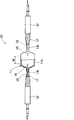
本発明のメタルハライドランプを、添付の図面を用いて説明する。図1は、本発明のメタルハライドランプの構成例を示す一部切り欠き正面図であり、そして図2は、図1のメタルハライドランプ10の拡大断面図である。但し、図2のメタルハライドランプ10は、電極棒14、モリブデン箔13、給電部材15、および電極端子16以外の部品についてのみ断面として図示してある。
The metal halide lamp of the present invention will be described with reference to the accompanying drawings. FIG. 1 is a partially cutaway front view showing a configuration example of a metal halide lamp of the present invention, and FIG. 2 is an enlarged cross-sectional view of the
メタルハライドランプ10は、内部に水銀及びメタルハライドを収容している中央領域にて膨出する透光性の発光部11aと、発光部11aの両側にそれぞれ備えられた側管部11bとを有する石英製の発光管11、各側管部11bの端部領域の周囲に装着された金属材料製の口金12、口金12よりも発光部11aの側にて各側管部内に気密封止されたモリブデン箔13、モリブデン箔13の発光部11aの側に接続されている電極棒14、およびモリブデン箔13の口金12の側に金属材料製の給電部材15を介して接続されている電極端子16などから構成されている。
The
そして、メタルハライドランプ10は、上記の各側管部11bの外周面に、モリブデン箔13の周囲の側管部の少なくとも一部(メタルハライドランプ10の場合には、モリブデン箔13の周囲の側管部の約1/2の長さの部分)が露出するようにして、口金12の端部から少なくとも給電部材15とモリブデン箔13との接続部21にまで(メタルハライドランプ10の場合には、モリブデン箔13の長さ方向の概ね中央の位置にまで)延びる不透明膜17が形成されていることに特徴がある。
The
発光管11は、石英製であり、中央領域にて棒出する透光性の発光部11aと、その両側にそれぞれ備えられている側管部11bとから構成されている。
The
発光部11aには、水銀及びメタルハライドが収容される。メタルハライドの例としては、Na、Tl、Th、In、Sn、Si、Sc、Dy、Ho、Tmなどの金属と沃素または臭素などのハロゲンとの化合物が挙げられる。発光部11aには、アルゴンなどの希ガスを収容することができる。 Mercury and metal halide are accommodated in the light emitting part 11a. Examples of metal halides include compounds of metals such as Na, Tl, Th, In, Sn, Si, Sc, Dy, Ho, and Tm and halogens such as iodine or bromine. The light emitting unit 11a can contain a rare gas such as argon.
発光部11aは「透光性」であることが必要である。「透光性」とは、波長が400〜4000nmの範囲にある光の透過率が70%以上であることを意味する。発光部11aの光透過率は75%以上であることが好ましく、80%以上であることが更に好ましい。 The light emitting part 11a needs to be “translucent”. “Translucent” means that the transmittance of light having a wavelength in the range of 400 to 4000 nm is 70% or more. The light transmittance of the light emitting part 11a is preferably 75% or more, and more preferably 80% or more.
側管部11bの端部領域の周囲には口金12が装着されている。口金12は、例えば、真鍮に代表される金属材料から形成される。口金12の表面の酸化を抑制するため、口金12の表面をめっき処理(例、ニッケルめっき処理)することもできる。
A
口金12よりも発光部11aの側において、各側管部11bの内部にはモリブデン箔13が気密封止されている。
Molybdenum
モリブデン箔13としては、モリブデン製のフィルムが用いられる。モリブデン箔13の厚みは、一般に5〜200μm、好ましくは10〜150μmの範囲内に設定される。
As the
モリブデン箔13には、更に一枚あるいは二枚以上のモリブデン箔を重ねて配置することもできる。モリブデン箔13が、合計で二枚以上のモリブデン箔から構成されているときには、互いに隣接するモリブデン箔の間に電気的に絶縁性を示す材料(例、石英)から形成された薄板を配置することもできる。
One or two or more molybdenum foils can be further stacked on the
モリブデン箔13は、側管部11bが熱膨張した際に塑性変形し、これにより側管部11bのモリブデン箔13と接触する部位に発生する熱応力を低減する機能を有している。
The
しかしながら、モリブデン箔13は、上記塑性変形を可能とするため薄い厚みに設定されるため電気抵抗が大きく、その内部を流れる電流によって大きなジュール熱を発生させる。そして、モリブデン箔が高温になり劣化(例、酸化膨張)すると、モリブデン箔に接触する側管部にクラックが発生して気密封止が不十分になったり、モリブデン箔の切断により電極棒に電気エネルギーを供給することができなくなったりすることがある。
However, since the
一方、後述の電極棒14の基部に巻き付けられているモリブデンフィルム18a、そして給電部材15の棒材15aの端部領域に巻き付けられているモリブデンフィルム18bとしても、上記のモリブデン箔13と同様に、それぞれモリブデン製のフィルムが用いられる。しかしながら、モリブデンフィルム18a、18bの各々は、導電性の部品(電極棒14あるいは棒材15a)に巻き付けられて電気的に接続された状態において小さな電気抵抗の値を示すため、上記のような大きなジュール熱を発生させることはなく、従って上記劣化の問題を生じ難い。このような理由により、本願明細書では、上記モリブデンフィルム(導電性の部品に巻き付けられたモリブデン製のフィルム)18a、18bと、上記モリブデン箔(導電性の部品に巻き付けられていないモリブデン製のフィルム)13とを互いに区別している。
On the other hand, the
モリブデン箔13の発光部11aの側には電極棒14が接続されている。電極棒14の先端部は、発光部11aの内部に突き出されている。電極棒14は、例えば、タングステンから形成される。前記のように、電極棒14の基部にはモリブデンフィルム18aが巻き付けられている。
An
モリブデン箔13の口金12の側には金属材料製の給電部材15を介して電極端子16が接続されている。
An electrode terminal 16 is connected to the base 12 side of the
給電部材15は、例えば、タングステン製の棒材15a、銅製のより線15b、およびモリブデン製の棒材15cから構成されている。前記のように、タングステン製の棒材15aの端部領域には、モリブデンフィルム18bが巻き付けられている。より線15bは、給電部材15が熱膨張した際に変形し、この熱膨張による給電部材15の伸びを吸収することにより、側管部11bに発生する熱応力を低減する働きをする。
The
給電部材15の棒材15cには、電極端子16の一方の端部が接続されている。電極端子16の他方の端部は、発光管11の外部に突き出されている。電極端子16としては、例えば、モリブデン製の棒材が用いられる。
One end of the electrode terminal 16 is connected to the
メタルハライドランプ10の構成は、次に説明する不透明膜を除いて、公知のメタルハライドランプの構成と同様であるので、これ以上の説明は行なわない。
Since the configuration of the
図1及び図2に示すメタルハライドランプ10では、上記の各側管部11bの外周面に、モリブデン箔13の周囲の側管部の約1/2の長さ(すなわちモリブデン箔13の全長の約1/2の長さ)の部分が露出するようにして、口金12の端部からモリブデン箔13の長さ方向の概ね中央の位置にまで延びる不透明膜17が形成されている。
In the
この不透明膜17により、発光部11aにて発生するアーク放電の放射熱が遮られ、側管部11bの口金12よりも発光部11aの側の部位の温度上昇が抑制される。このため、側管部11bの口金12の内側の部位に伝わる熱の量も少なくなり、側管部における熱応力の発生が十分に低減される。従って、側管部の口金12(金属材料製の部品)と接触する部位におけるクラックの発生が抑制される。
The
本発明では、アーク放電の放射熱を遮って側管部11bの温度上昇を抑制するため、上記の不透明膜17を、側管部11bの外周面の口金12の端部から少なくとも給電部材15とモリブデン箔13との接続部21の位置に対応する位置にまで延びるように形成する。なお、不透明膜を、更に口金の外周面に形成することもできる。
In the present invention, in order to block the radiant heat of the arc discharge and suppress the temperature rise of the side tube portion 11b, the
不透明膜17は、側管部11bの上記接続部21の位置に対応する位置よりも発光部11aの側に延びていてもよいが、前記のようにモリブデン箔13では大きなジュール熱が発生するため、不透明膜17がモリブデン箔の周囲への放熱を妨げることがある。
The
従って、本発明では、上記の不透明膜17を、モリブデン箔13の周囲の側管部の少なくとも一部が露出するようにして(モリブデン箔13の周囲の側管部の全体が不透明膜で覆われることのないようにして)側管部11bの外周面に形成する。
Accordingly, in the present invention, the
モリブデン箔13の周囲への放熱が良好であると、モリブデン箔13とその周囲の側管部の温度上昇が抑制される。従って、側管部11bのモリブデン箔13(金属材料製の部品)と接触する部位におけるクラックの発生が抑制される。
If the heat release to the periphery of the
モリブデン箔13の周囲の側管部は、その全長(すなわちモリブデン箔13の全長に等しい)の1/3以上、特に1/2以上の長さの部分が露出していることが好ましい。
The side tube portion around the
以上のように、本発明のメタルハライドランプ10は、側管部11bの金属材料製の部品(モリブデン箔13や口金12)と接触する部位におけるクラックの発生が抑制され、クラックからの水銀やメタルハライドの蒸気の漏れ出しの発生が抑制されることから、長期間の繰り返し使用が可能で、また側管部11bの外周面の所定領域に不透明膜を形成することにより容易に製造することができる。
As described above, in the
不透明膜17は、発光部11aで生じるアーク放電による放射熱を遮ることができれば、膜の色に特に制限はない。不透明膜17としては、例えば、公知の黒色膜あるいは白色膜を用いることができる。なお、「不透明」とは、波長が400〜4000nmの範囲にある光の透過率が40%以下であることを意味する。不透明膜の光透過率は35%以下であることが好ましく、30%以下であることが更に好ましい。
The
黒色膜は、黒色顔料粉末及びバインダを含むことが好ましい。黒色顔料粉末としては、例えば、四三酸化鉄の粉末を用いることができる。バインダとしては公知の無機ポリマー(例、金属酸化物系ポリマー)を用いることが好ましい。 The black film preferably contains black pigment powder and a binder. As the black pigment powder, for example, a powder of triiron tetroxide can be used. It is preferable to use a known inorganic polymer (eg, metal oxide polymer) as the binder.
白色膜は、白色顔料粉末及びバインダを含むことが好ましい。白色顔料粉末としては、例えば、酸化チタン(TiO2)あるいは酸化ジルコニウム(ZrO2)の粉末を用いることができる。バインダとしては公知の無機ポリマー(例、金属酸化物系ポリマー)を用いることが好ましい。 The white film preferably contains white pigment powder and a binder. As the white pigment powder, for example, titanium oxide (TiO 2 ) or zirconium oxide (ZrO 2 ) powder can be used. It is preferable to use a known inorganic polymer (eg, metal oxide polymer) as the binder.
図1及び図2に示すメタルハライドランプ10の不透明膜17としては、発光部11aで生じるアーク放電による放射熱を効率良く反射して、側管部11bの温度上昇を効果的に抑制することができることから、白色膜が用いられている。
The
不透明膜17は、上記の顔料粉末とバインダとを含む塗布液を、発光管11の側管部11bの外周面に塗布あるいは吹き付けし、次いで乾燥することにより形成することができる。
The
不透明膜の厚みは、5〜500μmの範囲にあることが好ましい。 The thickness of the opaque film is preferably in the range of 5 to 500 μm.
本発明のメタルハライドランプでは、各側管部11bがモリブデン箔13よりも口金12の側(側管部11bの端部の側)にて更に気密封止されていることが好ましい。
In the metal halide lamp of the present invention, it is preferable that each side tube portion 11b is further hermetically sealed on the base 12 side (end portion side of the side tube portion 11b) with respect to the
図2に示すメタルハライドランプ10の側管部11bの端部の内側面には、二個の石英製の筒体19a、19bが嵌め合わされて固定(例、溶着)されている。筒体19aの端部は、モリブデン製の筒状部材20に固定(例、溶着)されている。そして側管部11bは、筒状部材20が給電部材15の棒材15cの周囲にろう付けされることにより気密封止されている。これにより、不透明膜17により温度上昇が抑制された側管部11bを、高温のアーク放電から離れた比較的に低温の部位にて確実に気密封止することができる。
Two quartz cylinders 19a and 19b are fitted and fixed (eg, welded) to the inner side surface of the end portion of the side tube portion 11b of the
側管部11bの追加で気密封止が行なわれる位置と電極棒14の先端と対応する位置との距離(図2:L)は、一対の電極棒の間の距離(図1:W)と等しいか、それ以上であること(すなわちL≧Wの関係を満足すること)が好ましい。
The distance (FIG. 2: L) between the position where the hermetic sealing is performed with the addition of the side tube portion 11b and the position corresponding to the tip of the
上記の距離Lが大きいほど、側管部11bをより低温の部位にて確実に封止することができるが、側管部が長くなる。従って、上記距離Lは、距離Wの1〜15倍の範囲内にあることが好ましく、2〜10倍の範囲内にあることが更に好ましい。 As the distance L is larger, the side tube portion 11b can be reliably sealed at a lower temperature portion, but the side tube portion becomes longer. Therefore, the distance L is preferably in the range of 1 to 15 times the distance W, and more preferably in the range of 2 to 10 times.
先ず、白色膜(不透明膜)が形成されていないこと以外は図1及び図2に示すメタルハライドランプ10と同一の構成を有するメタルハライドランプを用意した。
First, a metal halide lamp having the same configuration as the
このメタルハライドランプの口金に透孔を形成し、この透孔から熱電対を挿入し、これを側管部の外周面上で、図2に示す筒状部材20と棒材15cとが接触する位置と対応する位置に固定した。これにより、ランプの周囲の空気の流れの影響を受けることなく、側管部の温度を安定に測定することができる。
A through hole is formed in the base of the metal halide lamp, a thermocouple is inserted through the through hole, and a position where the
次に、白色膜を形成していないメタルハライドランプの点灯を開始してから60分後に熱電対を用いて側管部の温度を測定したのち、ランプを消灯して放冷した。 Next, 60 minutes after starting the lighting of the metal halide lamp on which the white film was not formed, the temperature of the side tube portion was measured using a thermocouple, and then the lamp was turned off and allowed to cool.
続いて、上記のメタルハライドランプの各側管部の外周面に、白色顔料粉末(酸化ジルコニウムの粉末)とバインダ(有機金属ポリマー)とを含有する白色塗料の塗布膜を形成し、この塗布膜を常温にて乾燥することにより白色膜(不透明膜)を形成した。白色膜は、側管部の外周面の口金の端部からモリブデン箔の長さ方向の概ね中央の位置に対応する位置までの領域に形成し、これによりモリブデン箔の周囲の側管部の約1/2の長さ(すなわちモリブデン箔の全長の約1/2の長さ)の部分を露出させた。 Subsequently, a white paint coating film containing white pigment powder (zirconium oxide powder) and a binder (organometallic polymer) is formed on the outer peripheral surface of each side tube portion of the metal halide lamp. A white film (opaque film) was formed by drying at room temperature. The white film is formed in a region from the end of the mouthpiece on the outer peripheral surface of the side tube portion to a position corresponding to the substantially central position in the length direction of the molybdenum foil, and thereby, about the side tube portion around the molybdenum foil. A portion having a length of 1/2 (that is, a length of about 1/2 of the entire length of the molybdenum foil) was exposed.
このようにして白色膜を形成したメタルハライドランプの構成は、口金に上記透孔が形成されていることを除き、図1及び図2に示すメタルハライドランプ10の構成と同一である。
The configuration of the metal halide lamp thus formed with the white film is the same as that of the
そして、白色膜を形成したメタルハライドランプの点灯を開始してから60分後に熱電対を用いて側管部の温度を測定したのち、ランプを消灯して放冷した。 Then, 60 minutes after starting the lighting of the metal halide lamp on which the white film was formed, the temperature of the side tube portion was measured using a thermocouple, and then the lamp was turned off and allowed to cool.
上記の白色膜を形成していないメタルハライドランプについて測定された側管部の温度と、白色膜を形成したメタルハライドランプについて測定された側管部の温度との差は約100℃であり、白色膜が側管部の温度上昇の抑制に極めて有効であることを確認した。 The difference between the temperature of the side tube portion measured for the metal halide lamp not forming the white film and the temperature of the side tube portion measured for the metal halide lamp forming the white film is about 100 ° C. Has been confirmed to be extremely effective in suppressing the temperature rise in the side tube.
更に、上記の白色膜を形成したメタルハライドランプを3時間点灯させ、次いで1時間消灯する操作を85回繰り返したのち、発光管の側管部の目視での観察を行なった。その結果、発光管の側管部の口金に接触する部位、そして側管部のモリブデン箔に接触する部位にクラックが発生していないことを確認した。 Further, after repeating the operation of turning on the metal halide lamp on which the white film was formed for 3 hours and then turning it off for 1 hour 85 times, the side tube portion of the arc tube was visually observed. As a result, it was confirmed that no cracks were generated in the portion of the arc tube that contacts the base of the side tube portion and the portion of the side tube portion that contacts the molybdenum foil.
10 メタルハライドランプ
11 発光管
11a 発光部
11b 側管部
12 口金
13 モリブデン箔
14 電極棒
15 給電部材
15a 棒材
15b より線
15c 棒材
16 電極端子
17 不透明膜
18a、18b モリブデンフィルム
19a、19b 筒体
20 筒状部材
21 給電部材15とモリブデン箔13との接続部
DESCRIPTION OF
Claims (3)
上記の各側管部の外周面に、該モリブデン箔の周囲の側管部の少なくとも一部が露出するようにして、該口金の端部から少なくとも上記の給電部材とモリブデン箔との接続部にまで延びる不透明膜が形成されていることを特徴とするメタルハライドランプ。 A quartz arc tube having a translucent light emitting part bulging in a central region containing mercury and metal halide inside, and side tube parts respectively provided on both sides of the light emitting part, and each side tube A base made of a metal material mounted around the end region of the part, a molybdenum foil hermetically sealed in each side tube part on the side of the light emitting part from the base, and connected to the light emitting part side of the molybdenum foil A metal halide lamp including an electrode terminal and an electrode terminal connected to a base side of the molybdenum foil via a power feeding member made of a metal material,
At least a part of the side tube portion around the molybdenum foil is exposed on the outer peripheral surface of each side tube portion, and at least from the end of the base to the connection portion between the power feeding member and the molybdenum foil. A metal halide lamp characterized in that an opaque film extending to
Priority Applications (1)
| Application Number | Priority Date | Filing Date | Title |
|---|---|---|---|
| JP2011037039A JP2012174585A (en) | 2011-02-23 | 2011-02-23 | Metal halide lamp |
Applications Claiming Priority (1)
| Application Number | Priority Date | Filing Date | Title |
|---|---|---|---|
| JP2011037039A JP2012174585A (en) | 2011-02-23 | 2011-02-23 | Metal halide lamp |
Publications (1)
| Publication Number | Publication Date |
|---|---|
| JP2012174585A true JP2012174585A (en) | 2012-09-10 |
Family
ID=46977311
Family Applications (1)
| Application Number | Title | Priority Date | Filing Date |
|---|---|---|---|
| JP2011037039A Withdrawn JP2012174585A (en) | 2011-02-23 | 2011-02-23 | Metal halide lamp |
Country Status (1)
| Country | Link |
|---|---|
| JP (1) | JP2012174585A (en) |
Cited By (1)
| Publication number | Priority date | Publication date | Assignee | Title |
|---|---|---|---|---|
| WO2014170734A1 (en) * | 2013-04-15 | 2014-10-23 | 株式会社オーク製作所 | Discharge lamp |
-
2011
- 2011-02-23 JP JP2011037039A patent/JP2012174585A/en not_active Withdrawn
Cited By (6)
| Publication number | Priority date | Publication date | Assignee | Title |
|---|---|---|---|---|
| WO2014170734A1 (en) * | 2013-04-15 | 2014-10-23 | 株式会社オーク製作所 | Discharge lamp |
| CN105122423A (en) * | 2013-04-15 | 2015-12-02 | 株式会社Orc制作所 | Discharge lamp |
| KR20150140665A (en) * | 2013-04-15 | 2015-12-16 | 가부시키가이샤 오크세이사쿠쇼 | Discharge lamp |
| JPWO2014170734A1 (en) * | 2013-04-15 | 2017-02-16 | 株式会社オーク製作所 | Discharge lamp |
| TWI608518B (en) * | 2013-04-15 | 2017-12-11 | Orc Manufacturing Co Ltd | Discharge lamp |
| KR102190649B1 (en) | 2013-04-15 | 2020-12-14 | 가부시키가이샤 오크세이사쿠쇼 | Discharge lamp |
Similar Documents
| Publication | Publication Date | Title |
|---|---|---|
| JP2012531724A (en) | Xenon lamp using ceramic arc tube | |
| JP2012174585A (en) | Metal halide lamp | |
| US8664856B2 (en) | Electrode for a discharge lamp and a discharge lamp and method for producing an electrode | |
| JP2006302575A (en) | Lamp | |
| JP2015076334A (en) | Lamp | |
| JP2010225306A (en) | High-pressure discharge lamp and lighting system | |
| JP5648968B2 (en) | Xenon flash lamp lighting device | |
| JP2012009214A (en) | Metal halide lamp | |
| TW201003723A (en) | Metal halide lamp | |
| JP4379552B2 (en) | High pressure discharge lamp and lighting device | |
| JP2009140703A (en) | High-pressure discharge lamp and lighting fixture | |
| JP6287626B2 (en) | heater | |
| KR102221515B1 (en) | Xenon flash lamp | |
| JP3407555B2 (en) | Light irradiation device | |
| TW201241869A (en) | Ceramic discharge metal halide (CDM) lamp and method of manufacture thereof | |
| JP6426374B2 (en) | Discharge lamp and halogen lamp, and method of manufacturing the lamp | |
| JP3911924B2 (en) | Tube | |
| JP4433426B2 (en) | High pressure discharge lamp and lighting device | |
| JP6294901B2 (en) | Mercury discharge lamp | |
| TW200818238A (en) | Discharge lamp with ignition anxiliary element | |
| KR200314690Y1 (en) | carbon heat radiation lamp | |
| JP6803524B2 (en) | Light emitting device including a flash discharge tube and a flash discharge tube | |
| JP2015065109A (en) | Xenon flash lamp | |
| WO2009144904A1 (en) | Discharge lamp with reflector | |
| JP5338557B2 (en) | Lamp with base |
Legal Events
| Date | Code | Title | Description |
|---|---|---|---|
| RD04 | Notification of resignation of power of attorney |
Free format text: JAPANESE INTERMEDIATE CODE: A7424 Effective date: 20121220 |
|
| A300 | Withdrawal of application because of no request for examination |
Free format text: JAPANESE INTERMEDIATE CODE: A300 Effective date: 20140513 |