JP2012173293A - Method and system for sensor interface having dynamic and automatic gain control function depending on speed - Google Patents
Method and system for sensor interface having dynamic and automatic gain control function depending on speed Download PDFInfo
- Publication number
- JP2012173293A JP2012173293A JP2012033480A JP2012033480A JP2012173293A JP 2012173293 A JP2012173293 A JP 2012173293A JP 2012033480 A JP2012033480 A JP 2012033480A JP 2012033480 A JP2012033480 A JP 2012033480A JP 2012173293 A JP2012173293 A JP 2012173293A
- Authority
- JP
- Japan
- Prior art keywords
- voltage signal
- signal
- attenuated
- ended
- attenuated single
- Prior art date
- Legal status (The legal status is an assumption and is not a legal conclusion. Google has not performed a legal analysis and makes no representation as to the accuracy of the status listed.)
- Pending
Links
Images
Classifications
-
- G—PHYSICS
- G01—MEASURING; TESTING
- G01P—MEASURING LINEAR OR ANGULAR SPEED, ACCELERATION, DECELERATION, OR SHOCK; INDICATING PRESENCE, ABSENCE, OR DIRECTION, OF MOVEMENT
- G01P3/00—Measuring linear or angular speed; Measuring differences of linear or angular speeds
- G01P3/42—Devices characterised by the use of electric or magnetic means
- G01P3/44—Devices characterised by the use of electric or magnetic means for measuring angular speed
- G01P3/46—Devices characterised by the use of electric or magnetic means for measuring angular speed by measuring amplitude of generated current or voltage
-
- G—PHYSICS
- G01—MEASURING; TESTING
- G01P—MEASURING LINEAR OR ANGULAR SPEED, ACCELERATION, DECELERATION, OR SHOCK; INDICATING PRESENCE, ABSENCE, OR DIRECTION, OF MOVEMENT
- G01P3/00—Measuring linear or angular speed; Measuring differences of linear or angular speeds
- G01P3/42—Devices characterised by the use of electric or magnetic means
- G01P3/44—Devices characterised by the use of electric or magnetic means for measuring angular speed
- G01P3/48—Devices characterised by the use of electric or magnetic means for measuring angular speed by measuring frequency of generated current or voltage
- G01P3/481—Devices characterised by the use of electric or magnetic means for measuring angular speed by measuring frequency of generated current or voltage of pulse signals
- G01P3/487—Devices characterised by the use of electric or magnetic means for measuring angular speed by measuring frequency of generated current or voltage of pulse signals delivered by rotating magnets
-
- G—PHYSICS
- G01—MEASURING; TESTING
- G01P—MEASURING LINEAR OR ANGULAR SPEED, ACCELERATION, DECELERATION, OR SHOCK; INDICATING PRESENCE, ABSENCE, OR DIRECTION, OF MOVEMENT
- G01P3/00—Measuring linear or angular speed; Measuring differences of linear or angular speeds
- G01P3/42—Devices characterised by the use of electric or magnetic means
- G01P3/44—Devices characterised by the use of electric or magnetic means for measuring angular speed
- G01P3/48—Devices characterised by the use of electric or magnetic means for measuring angular speed by measuring frequency of generated current or voltage
- G01P3/481—Devices characterised by the use of electric or magnetic means for measuring angular speed by measuring frequency of generated current or voltage of pulse signals
- G01P3/488—Devices characterised by the use of electric or magnetic means for measuring angular speed by measuring frequency of generated current or voltage of pulse signals delivered by variable reluctance detectors
Landscapes
- Physics & Mathematics (AREA)
- General Physics & Mathematics (AREA)
- Transmission And Conversion Of Sensor Element Output (AREA)
- Measurement Of Length, Angles, Or The Like Using Electric Or Magnetic Means (AREA)
Abstract
Description
本願は、速度に依存する動的自動利得制御機能を有するセンサインタフェースの方法及びシステムに関する。本出願は、参照によりその全体が本明細書に組み込まれ、本明細書の一部をなす、2011年2月23日に出願された米国特許出願第13/033249号(GE整理番号第247779号)に関連する。 The present application relates to a sensor interface method and system having a speed-dependent dynamic automatic gain control function. This application is incorporated by reference in its entirety, and is incorporated herein by reference, US patent application Ser. No. 13/033249 filed Feb. 23, 2011 (GE Docket No. 247779). )is connected with.
多くの場合、例えば、電動機、発電機、内燃機関、ジェットエンジン、タービンなどのような機械や、これらによって駆動されるシステムは、性能特性及び動作特性(例えば、振動、熱、ノイズ、速度など)、電気的特性(例えば、電流、電圧、抵抗など)、環境影響などに関して、様々な監視システムによる能動的監視が行われる。一般に、これらの機械を監視する監視システムは、その機械の近傍に配置されて、その機械に関連付けられた、1つ以上のセンサ又はトランスデューサを含む。例えば、監視システムは、受動磁気センサや磁気抵抗センサを用いることが可能である。以下では、これらのセンサを単に「センサ」、「磁気センサ」、又は「受動磁気センサ」と称することとし、これらは受動磁気センサ及び磁気抵抗センサを包含するものとする。 In many cases, for example, machines such as electric motors, generators, internal combustion engines, jet engines, turbines, etc., and systems driven by them, performance and operating characteristics (eg vibration, heat, noise, speed, etc.) Active monitoring by various monitoring systems is performed regarding electrical characteristics (eg, current, voltage, resistance, etc.), environmental effects, and the like. Generally, a monitoring system that monitors these machines includes one or more sensors or transducers that are located in the vicinity of the machine and associated with the machine. For example, the monitoring system can use a passive magnetic sensor or a magnetoresistive sensor. In the following, these sensors will be simply referred to as “sensors”, “magnetic sensors”, or “passive magnetic sensors”, which shall include passive magnetic sensors and magnetoresistive sensors.
一般に、受動磁気センサは、永久磁石とコイルとで構成されており、コイルの各側に信号線が接続されている。磁石からは磁界(磁束線)が発生し、これは、磁気センサの端部から空気中に広がる。鉄を含む物体が磁気センサの先端(即ち、プローブチップ)に近づくと、物体と、磁気センサに収容された磁石から発せられた磁界とが相互に作用して、コイルに電流が誘起され、これによって、交流(AC)電圧が発生する。この電圧を、磁気センサ出力として動作する信号線において検出することが可能である。磁束線が充満している領域にターゲットが入り、その後、そこから出ると、これによって、まず正の電圧ピークが発生し、その後に負の電圧ピークが発生する。この電圧出力は、本質的には正弦波状になりうるが、ターゲットの材料組成や形状に応じて歪む可能性がある。受動磁気センサから発生する出力信号の特性には、ターゲットの表面速度、ギャップの大きさ、ターゲットの形状、負荷インピーダンスなどを含むいくつかの要因が寄与する。 Generally, a passive magnetic sensor is composed of a permanent magnet and a coil, and a signal line is connected to each side of the coil. A magnetic field (magnetic flux line) is generated from the magnet and spreads in the air from the end of the magnetic sensor. When an object containing iron approaches the tip of the magnetic sensor (ie, the probe tip), the object and the magnetic field generated by the magnet housed in the magnetic sensor interact with each other, and an electric current is induced in the coil. Generates an alternating current (AC) voltage. This voltage can be detected on a signal line that operates as a magnetic sensor output. When the target enters the area where the magnetic flux lines are full and then exits, this first causes a positive voltage peak and then a negative voltage peak. This voltage output can be essentially sinusoidal but can be distorted depending on the material composition and shape of the target. Several factors contribute to the characteristics of the output signal generated from the passive magnetic sensor, including the target surface velocity, gap size, target shape, load impedance, and the like.
表面速度は、ターゲットが磁気センサのプローブチップのそばを通過する際の速度であって、磁気センサから発生するパルスの振幅に直接影響する。ターゲット速度と出力電圧とを関連付ける厳密な関数は磁気センサごとに異なるが、速度と出力電圧との間の相関はほぼ線形関数(比例)である。ギャップの大きさは、ターゲットが磁気センサのプローブチップのそばを通過する際のターゲットとプローブチップとの間の距離を意味し、これも出力電圧に影響を及ぼす。ギャップが小さいほど、出力電圧は大きくなる。磁気センサのギャップの設定値は、およそ25ミルから30ミルが一般的である。一般に、ギャップの大きさと電圧出力との関係は、本質的に非線形である。ギャップを小さくすると、出力電圧が大幅に増加する可能性がある。ターゲットの形状寸法も、出力電圧の振幅及び形状に影響を及ぼす可能性がある。一般に、ターゲットが大きいほど、振幅は大きくなる。磁気センサの内部インピーダンスから見た相対的な負荷インピーダンスは、その負荷によって検出される磁気センサ出力電圧の大きさに影響を及ぼす。磁気センサは、一般に、出力を最大にすることとの整合性を保ちながら実インピーダンスが最小になるように設計される。コイル両端における電圧降下を最小化し、最大出力を負荷に与えるためには、負荷インピーダンスを、磁気センサのインピーダンスとの関連で高くしなければならない。一般に、負荷インピーダンスは、磁気センサの内部インピーダンスの少なくとも10倍にしなければならない。 The surface speed is the speed at which the target passes by the probe tip of the magnetic sensor and directly affects the amplitude of the pulse generated from the magnetic sensor. The exact function that associates the target speed with the output voltage is different for each magnetic sensor, but the correlation between the speed and the output voltage is almost a linear function (proportional). The size of the gap means the distance between the target and the probe tip when the target passes by the probe tip of the magnetic sensor, which also affects the output voltage. The smaller the gap, the greater the output voltage. The set value of the gap of the magnetic sensor is generally about 25 mil to 30 mil. In general, the relationship between gap size and voltage output is non-linear in nature. If the gap is reduced, the output voltage can increase significantly. The target geometry can also affect the amplitude and shape of the output voltage. In general, the larger the target, the greater the amplitude. The relative load impedance viewed from the internal impedance of the magnetic sensor affects the magnitude of the magnetic sensor output voltage detected by the load. Magnetic sensors are generally designed to minimize real impedance while maintaining consistency with maximizing output. In order to minimize the voltage drop across the coil and provide maximum output to the load, the load impedance must be increased in relation to the impedance of the magnetic sensor. In general, the load impedance should be at least 10 times the internal impedance of the magnetic sensor.
磁気センサを用いることの利点としては、磁気センサが受動的であるために外部電力が不要であること、磁気センサが非常にシンプルな設計であるために信頼性が高いこと、磁気センサが一般に低コストであることなどが挙げられる。しかしながら、これらのセンサを使用することには課題もある。課題の1つは、出力信号の振幅が速度によって大きく変動しうることである。このため、機械の(例えば、ゼロから3600rpmまで加速する)始動時データ特性を解析することが困難になる可能性がある。例えば、磁気センサの出力電圧は、ターゲットの通過速度に対して大幅に(例えば、10mVp−pから200Vp−pまで)変化する。この特性が問題になる可能性があるのは、ターゲットが低速で通過する際の磁気センサ出力を、ターゲットが高速で通過する際の出力と同じ精度で監視する場合である。低速の信号の場合は、信号対ノイズ比を改善するために増幅することが必要であるのに対し、高速の信号の場合は、回路上の制約によるクリッピングや歪みを防ぐために減衰させることが必要である。又、別の課題として、磁気センサが受動的であるために、磁気ピックアップの駆動力が小さく、ケーブルが長い場合には信号を駆動することができない。更に、磁気センサは、正確なギャップ読み(gap reading)には使用できない。振幅はギャップを表すことが可能であるが、与えられた出力電圧から、ギャップの大きさを正確に決定することはできない。これは、上述のように、他の様々な要因が出力に影響を及ぼすためである。 The advantages of using a magnetic sensor are that the magnetic sensor is passive and requires no external power, the magnetic sensor has a very simple design and is highly reliable, and the magnetic sensor is generally low. It is cost. However, there are problems with using these sensors. One problem is that the amplitude of the output signal can vary greatly with speed. This can make it difficult to analyze the start-up data characteristics of the machine (eg, accelerating from zero to 3600 rpm). For example, the output voltage of the magnetic sensor varies significantly (eg, from 10 mVp-p to 200 Vp-p) with respect to the target passing speed. This characteristic can be a problem when the output of the magnetic sensor when the target passes at a low speed is monitored with the same accuracy as the output when the target passes at a high speed. Low-speed signals need to be amplified to improve the signal-to-noise ratio, whereas high-speed signals need to be attenuated to prevent clipping and distortion due to circuit constraints It is. As another problem, since the magnetic sensor is passive, the driving force of the magnetic pickup is small and the signal cannot be driven when the cable is long. Furthermore, magnetic sensors cannot be used for accurate gap reading. Although the amplitude can represent a gap, the size of the gap cannot be accurately determined from a given output voltage. This is because various other factors affect the output as described above.
そこで、当該技術分野における課題(そのいくつかは上述のとおりである)を克服するシステム及び方法が必要とされている。具体的には、ターゲットが低速で通過する際の磁気センサ出力及び同じターゲットが高速で通過する際の磁気センサ出力の精度を改善できる、速度入力を用いた動的自動利得制御機能を磁気センサに与えることが、上述の課題に対処する上で有用であろう。 Thus, there is a need for systems and methods that overcome problems in the art, some of which are described above. Specifically, the magnetic sensor has a dynamic automatic gain control function using velocity input that can improve the accuracy of the magnetic sensor output when the target passes at a low speed and the magnetic sensor output when the same target passes at a high speed. Giving would be useful in addressing the above-mentioned challenges.
本明細書に記載の本発明の実施形態は、所与のターゲットの速度範囲全体(0〜最大rpm)にわたって入力信号の真の正ピーク及び負ピークが維持されるように、ターゲットの現在の速度を表す速度信号を用いて信号調整処理を動的に調節することにより、低速時の信号対ノイズ比を高め、高速時のクリッピングや歪みを防ぐことが可能な磁気センサインタフェースを提供する。 The embodiments of the present invention described herein allow the current speed of the target to be maintained so that the true positive and negative peaks of the input signal are maintained over the entire speed range (0 to max rpm) for a given target. A magnetic sensor interface capable of increasing a signal-to-noise ratio at a low speed and preventing clipping and distortion at a high speed by dynamically adjusting a signal adjustment process using a speed signal representing the above.
一態様では、方法を示す。本方法は、センサから交流差動電圧信号を受信するステップを含む。交流差動電圧信号の振幅は、ターゲットの速度変化に応じて変化する。交流差動電圧信号は、動的スケーリングが可能な減衰済みシングルエンデッド電圧信号に変換される。減衰済みシングルエンデッド電圧信号にスケーリング係数を乗じることにより、減衰済みシングルエンデッド電圧信号をスケーリングすることが可能である。スケーリング係数は、速度信号に応じて選択され、且つ、スケーリングされた減衰済みシングルエンデッド電圧信号の信号対ノイズ比に応じて選択される。 In one aspect, a method is shown. The method includes receiving an AC differential voltage signal from a sensor. The amplitude of the AC differential voltage signal changes according to the speed change of the target. The AC differential voltage signal is converted to an attenuated single-ended voltage signal that can be dynamically scaled. It is possible to scale the attenuated single-ended voltage signal by multiplying the attenuated single-ended voltage signal by a scaling factor. The scaling factor is selected as a function of the speed signal and as a function of the signal to noise ratio of the scaled attenuated single-ended voltage signal.
別の態様では、システムを示す。本システムは、ターゲットの速度変化に応じて振幅が変化する交流差動電圧信号を発生させるように構成されたセンサを含む。更に、本システムは、交流差動電圧信号を受信し、交流差動電圧信号を減衰済みシングルエンデッド電圧信号に変換する、第1の回路を含む。速度センサ又は速度トランスデューサが、ターゲットの現在の速度を示す速度信号を発生させる。第2の回路は、減衰済みシングルエンデッド電圧信号にスケーリング係数を乗じることにより、減衰済みシングルエンデッド電圧信号を動的にスケーリングする。スケーリング係数は、速度信号に応じて選択され、且つ、スケーリングされた減衰済みシングルエンデッド電圧信号の信号対ノイズ比に応じて選択される。 In another aspect, a system is shown. The system includes a sensor configured to generate an AC differential voltage signal that varies in amplitude in response to changes in target velocity. The system further includes a first circuit that receives the AC differential voltage signal and converts the AC differential voltage signal to an attenuated single-ended voltage signal. A speed sensor or speed transducer generates a speed signal indicative of the current speed of the target. The second circuit dynamically scales the attenuated single-ended voltage signal by multiplying the attenuated single-ended voltage signal by a scaling factor. The scaling factor is selected as a function of the speed signal and as a function of the signal to noise ratio of the scaled attenuated single-ended voltage signal.
更なる利点は、その一部が下記の記述において記載されているか、或いは実践を通じて習得可能である。これらの利点は、添付の特許請求の範囲で特記した要素及び組み合わせによって実現及び達成されよう。上記の概要及び下記の記述は、クレームされている通り、あくまでも例示及び説明のためのものであって、限定的なものではないことを理解されたい。 Further advantages are described in part in the description below or can be learned through practice. These advantages will be realized and attained by means of the elements and combinations particularly pointed out in the appended claims. It is to be understood that the above summary and the following description are only for purposes of illustration and description, and are not limiting, as claimed.
添付図面は、本明細書に組み込まれていて本明細書の一部をなすものであり、実施形態を図示し、本明細書とともに、本方法及びシステムの原理を説明する役割を担っている。 The accompanying drawings, which are incorporated in and constitute a part of this specification, illustrate embodiments and, together with this specification, serve to explain the principles of the method and system.
本方法及びシステムを開示及び記述する前に、本方法及びシステムが特定の統合方法、特定の部品、又は特定の構成に限定されることはない、ということを理解されたい。また、本明細書で使用する用語は、あくまでも特定の実施形態を記述するためのものであって、限定を意図したものではない。 Before disclosing and describing the method and system, it is to be understood that the method and system are not limited to a particular integration method, particular component, or particular configuration. The terms used in the present specification are only for describing specific embodiments, and are not intended to be limiting.
本明細書及び添付の特許請求の範囲で使用する際、文脈上明記しない限り、単数名詞は複数の指示対象も包含する。「約〜(或る特定の値)から、及び/又は、約・・・(別の特定の値)まで」という形で範囲を表現することがある。こうした範囲表現のときは、別の実施形態が、上記或る特定の値から、及び/又は、上記別の特定の値を含む。同様に、近似値として値を表現するときは、「約」を先立って使用することにより、その特定の値が別の実施形態を構成することが理解できよう。また、各範囲の端点は、別の端点に関して有意であり、且つ別の端点とは別個に有意である。更に、本明細書において範囲を例示するときは、示されている範囲には、特に明記しない限り、その間にある部分的な範囲も全て含まれることを認識されたい。 As used in this specification and the appended claims, a singular noun includes a plurality of referents unless the context clearly indicates otherwise. A range may be expressed in the form of “about to (a specific value) and / or about... (Another specific value)”. With such a range representation, another embodiment includes from the one particular value and / or the other particular value. Similarly, when expressing a value as an approximation, it will be understood that by using “about” in advance, that particular value constitutes another embodiment. Also, the endpoints of each range are significant with respect to another endpoint and are significant separately from the other endpoint. Further, when ranges are exemplified in this specification, it is to be understood that the ranges shown include all partial ranges in between, unless otherwise specified.
「任意の」又は「任意で」とは、これに続いて記述される事象又は状況が生じることも生じないこともあり、当該記述には、当該事象又は状況が生じる場合も、当該事象又は状況が生じない場合も含まれることを意味する。 “Any” or “optional” may or may not result from the event or situation described subsequently, and the description may include the event or situation, even if the event or situation occurs. It means that the case where no occurs.
本明細書及び特許請求の範囲を通じて、「有する」や、その変形である「備える」「含む」等の変形は、「〜を含むがそれに限定されない」ことを意味しており、例えば、その他の追加物、部品、整数値、又はステップ等を排除することを意図したものではない。「例示的な」とは、「〜の一例」であることを意味し、好適又は理想的な実施形態を示唆することを意図したものではない。「〜等の」は、限定的な意味で用いられるのではなく、説明するために用いられる。 Throughout the present specification and claims, variations such as “having” and its variations “including” and “including” mean “including but not limited to”, for example, other It is not intended to exclude additions, parts, integer values, or steps. “Exemplary” means “an example of” and is not intended to suggest preferred or ideal embodiments. “Such as” is not used in a limiting sense, but for explanatory purposes.
開示されるのは、開示の方法及びシステムの実施に使用可能な部品である。本明細書では、これら及びその他の部品を開示するが、これらの部品の組み合わせ、サブセット、相互作用、集合等を開示する際、これらの個々の及び集合的な組み合わせ及び置換が明記されていないこともあるが、本明細書では、全ての方法及びシステムについて、それぞれが具体的に熟慮されたものであることを理解されたい。このことは、(これに限定されることはないが)開示の方法ステップを含む、本願の全ての態様についても同じである。従って、実施可能な様々なステップが更に存在する場合、これらの更なるステップを、いずれの特定の実施形態とも一緒に実施可能であり、或いは、開示の方法の実施形態のいずれの組み合わせにおいても実施可能であることを理解されたい。 Disclosed are parts that can be used to implement the disclosed methods and systems. This specification discloses these and other parts, but when disclosing combinations, subsets, interactions, sets, etc. of these parts, these individual and collective combinations and permutations are not specified. However, it should be understood herein that each method and system is specifically contemplated. This is the same for all aspects of the present application including, but not limited to, the disclosed method steps. Thus, if there are further various steps that can be performed, these additional steps can be performed with any particular embodiment, or performed in any combination of the disclosed method embodiments. Please understand that this is possible.
好適な実施形態及びその中に含まれる実施例の詳細な説明を参照することにより、本方法及びシステムを容易に理解できる。 The method and system can be readily understood by reference to the detailed description of the preferred embodiments and the examples contained therein.
本明細書に記載のように、本発明の実施形態は、所与のターゲットの速度範囲全体(0〜最大rpm)にわたって磁気抵抗センサ又は磁気センサからの入力信号の真の正ピーク及び負ピークが維持されるように、信号調整処理を動的に、且つ、ターゲットからの速度信号に応じて調節することが可能な、磁気抵抗センサ又は磁気センサのインタフェース回路を提供する。磁気センサの出力電圧は、ターゲットの通過速度に対して大幅に(例えば、10mVp−pから200Vp−pまで)変化しうる。この特性が問題になるのは、ターゲットが低速で通過する際のセンサ出力を、ターゲットが高速で通過する際の出力と同じ精度で監視する場合である。低速の信号の場合は、信号対ノイズ比を改善するために増幅することが必要であるのに対し、高速の信号の場合は、回路上の制約によるクリッピングや歪みを防ぐために減衰させることが必要になる場合がある。そこで、本明細書に記載の実施形態の技術的効果は、所与のターゲットの速度範囲全体(0〜最大rpm)にわたって、そのターゲットの性能/挙動を、磁気センサでターゲットからの速度信号を用いて監視する方法を提供することである。本発明の実施形態によれば、以前であればノイズから分離することが困難であった、低振幅信号の信号内容を取り込むことが可能になる。又、実施形態によれば、広範囲のターゲット速度及びこれらに対応する信号振幅にわたって信号対ノイズ比を動的スケーリング及び速度信号の使用によって高めることが可能になる。 As described herein, embodiments of the present invention allow the true positive and negative peaks of an input signal from a magnetoresistive sensor or magnetic sensor over the entire speed range (0 to max rpm) for a given target. A magnetoresistive sensor or magnetic sensor interface circuit is provided that can adjust the signal conditioning process dynamically and in response to a velocity signal from the target to be maintained. The output voltage of the magnetic sensor can vary significantly (eg, from 10 mVp-p to 200 Vp-p) with respect to the target passing speed. This characteristic becomes a problem when the sensor output when the target passes at a low speed is monitored with the same accuracy as the output when the target passes at a high speed. Low-speed signals need to be amplified to improve the signal-to-noise ratio, whereas high-speed signals need to be attenuated to prevent clipping and distortion due to circuit constraints It may become. Thus, the technical effect of the embodiments described herein is that the performance / behavior of a target over the entire speed range (0 to max rpm) of a given target is measured using a velocity signal from the target with a magnetic sensor. Providing a way to monitor. According to the embodiment of the present invention, it is possible to capture the signal content of a low-amplitude signal that was difficult to separate from noise before. Embodiments also allow the signal to noise ratio to be increased through the use of dynamic scaling and velocity signals over a wide range of target velocities and their corresponding signal amplitudes.
本明細書に記載のシステム及び方法は、入力信号の真の正ピーク及び負ピークが維持されるように、信号調整処理を、ターゲットからの速度信号を用いて動的に調節することが可能な磁気センサインタフェース回路を提供する。一態様では、本インタフェース回路の一実施形態は、磁気センサから差動電圧を受信し、この差動電圧は、シングルエンデッド電圧に変換され、(必要であれば)信号のクリッピングを防ぐために減衰される。減衰済みシングルエンデッド電圧信号は、その信号対ノイズ比に応じて、信号波形をクリッピング又は変形させることなくスケーリング(増幅又は減衰)される。一態様では、減衰済みシングルエンデッド電圧信号は、信号対ノイズ比を改善又は最大化するようにスケーリングされる。一態様では、この増幅又は減衰は、デジタルプロセッサ又はフィールドプログラマブルゲートアレイ(FPGA)によって実行されるアルゴリズムによって選択され、このアルゴリズムは、少なくとも2つの入力を考慮する。第1の入力は、磁気センサのターゲットの速度を伝達する。第2の入力は、アナログデジタル変換器(ADC)から出力される、磁気センサの両端の接点で検出されたアナログ電圧のデジタル表現である。ADCは、その入力を、上述のスケーリングされた減衰済みシングルエンデッド電圧から受け取る。これによって与えられるフィードバックループにより、本発明の実施形態は、クリッピング又は信号変形の発生を検出し、これが発生しないようにスケーリングを調節することが可能である。実施形態は又、外部速度入力に基づいて信号の調整及びスケーリングを制御する仕組みを提供する。 The systems and methods described herein allow the signal conditioning process to be dynamically adjusted using the velocity signal from the target so that the true positive and negative peaks of the input signal are maintained. A magnetic sensor interface circuit is provided. In one aspect, an embodiment of the interface circuit receives a differential voltage from a magnetic sensor, which is converted to a single-ended voltage and attenuated (if necessary) to prevent signal clipping. Is done. The attenuated single-ended voltage signal is scaled (amplified or attenuated) depending on its signal to noise ratio without clipping or deforming the signal waveform. In one aspect, the attenuated single-ended voltage signal is scaled to improve or maximize the signal to noise ratio. In one aspect, this amplification or attenuation is selected by an algorithm executed by a digital processor or field programmable gate array (FPGA), which considers at least two inputs. The first input conveys the velocity of the magnetic sensor target. The second input is a digital representation of the analog voltage detected at the contacts across the magnetic sensor, output from an analog-to-digital converter (ADC). The ADC receives its input from the scaled attenuated single-ended voltage described above. With this provided feedback loop, embodiments of the present invention can detect the occurrence of clipping or signal deformation and adjust the scaling so that this does not occur. Embodiments also provide a mechanism for controlling signal adjustment and scaling based on an external speed input.
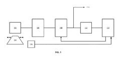
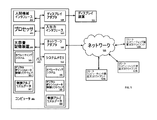
図1は、本発明の一実施形態の概略ブロック図を示す。センサ102は、センサ102のそばを通過するターゲット104を検出する。本明細書に記載のように、一態様では、センサ102は、受動磁気センサ又は磁気抵抗センサであってよい。一般に、ターゲット104がセンサ102のそばを通過すると、センサ102から電圧パルス又は信号が発生する。一方、別の態様では、センサ102がターゲット104のそばを通過すると、電圧信号が発生する。センサ102から発生した電圧信号は、いくつかの要因に関連しており、それらは、ターゲット104の材料、ターゲット104の幾何形状又は形状、ターゲット104とセンサ102との間のギャップの大きさ、ターゲット104がセンサ102のそばを通過する(又はセンサ102がターゲット104のそばを通過する)際の速度などである。一態様では、電圧信号は、交流差動電圧パルス(即ち、グラウンド又は他のいずれかの共通ポイントを基準としない信号)である。一態様では、電圧信号は、水平(ゼロ)軸に関して対称であっても非対称であってもよい。この交流電圧信号の振幅は、ターゲット104がセンサ102に近づき、センサ102の下方を通り、センサ102を通過する際に(又はセンサ102がターゲット104に近づき、ターゲット104を通過する際に)、時間とともに変化する。一態様では、この交流電圧信号の振幅は、ターゲット104の速度変化に応じて変化する。一態様では、この交流電圧信号は、正弦波である。一態様では、この交流電圧信号は、正弦波ではない。一態様では、センサ102は、多くの様々なメーカーのいずれかから入手可能な受動磁気センサである。一態様では、センサ102は、AI−Tek Instruments,Inc.(コネチカット州チェシャー)から入手可能な受動磁気センサ又は可変磁気抵抗センサであってよい。一態様では、センサ102は、AI−Tek 70085−1010型受動磁気センサであってよい。ターゲット104は、様々な装置であってよい。一態様では、ターゲット104は、タービン(例えば、蒸気タービン、ガスタービンなど)のブレードであってよい。一態様では、ターゲット104は、圧縮機(例えば、ガスタービンなどで使用される圧縮機など)のブレードであってよい。一態様では、ターゲット104は、歯車の歯であってよい。
FIG. 1 shows a schematic block diagram of one embodiment of the present invention. The
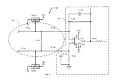
一態様では、センサ102から発生する交流差動電圧信号は、回路106によって受信される。一態様では、回路106は、交流差動電圧信号を受信し、この交流差動電圧信号を減衰済みシングルエンデッド電圧信号(即ち、グラウンド又は別の共通ポイントを基準とする信号)に変換する。一態様では、回路106は、交流差動電圧信号のピークツーピーク値に応じて、交流差動電圧信号を減衰させるか増幅する。一態様では、回路106は、交流差動電圧を固定量だけ減衰させる(即ち、交流差動電圧のピークツーピーク値を常に10パーセントだけ、15パーセントだけ、20パーセントだけ、というように減少させる)。一態様では、回路106は、交流差動電圧信号を減衰済みシングルエンデッド電圧信号に変換する。これは、減衰済みシングルエンデッド電圧信号が減衰済み最大電圧以下になるように、交流差動電圧信号を固定量だけ減衰させることにより、行う。一態様では、回路106は、交流差動電圧信号の最大ピークツーピーク値に対する減衰済み最大電圧の比を交流差動電圧信号に乗じることにより、交流差動電圧信号を、減衰済みシングルエンデッド電圧信号に変換する。一態様では、交流差動電圧信号の最大ピークツーピーク値は、約250ボルトピークツーピークであってよく、減衰済みシングルエンデッド電圧信号の減衰済み最大電圧は、約30ボルトピークツーピークであってよい。一態様では、回路106は、図2に示すように、抵抗分割器202と、シングルエンデッド出力を有する演算増幅器204とを含んでいる。図2は、本発明の一態様による、交流差動電圧信号を減衰済みシングルエンデッド電圧信号に変換することが可能な回路106の一実施形態の回路図である。一態様では、交流差動電圧信号を減衰済みシングルエンデッド電圧信号に変換することは、抵抗分割器202を用いて交流差動電圧信号を分割することと、シングルエンデッド出力を有する演算増幅器204に差動入力を与えることと、を含む。限定ではない一例として、抵抗分割器202は、R142=4.99キロオーム、R143=4.99キロオーム、R144=3.01キロオーム、R145=121キロオーム、及びR146=121キロオームの値を有するレジスタを含んでよい。又、限定ではない一例として、シングルエンデッド出力を有する演算増幅器回路204は、R147=49.9キロオーム、R148=49.9キロオーム、R284=2.0キロオーム、C103=5.6ピコファラド、及びC104=5.6ピコファラドの値を有するレジスタ及びキャパシタを含んでよい。図2の回路は、限定ではない例として示したものであり、同じ機能を別の回路で実現することも可能であることを理解されたい。
In one aspect, an AC differential voltage signal generated from
図1のシステムは更に、速度センサ116を含んでいる。速度センサ116は、ターゲット104が動いている現在の速度を検出し、ターゲット104の速度に応じた速度信号を発生させる。逆に、(ターゲット104が固定されていて、磁気センサ102が動いている場合には)速度センサ116は、磁気センサ102がターゲット104のそばを通過する際の速度を検出することが可能である。一態様では、速度センサ116からの速度信号は、フィールドプログラマブルゲートアレイ(FPGA)又はデジタルプロセッサ110に与えられ、FPGA又はデジタルプロセッサ110は、この速度信号を用いて、本明細書に記載のアルゴリズムに従って、減衰済みシングルエンデッド電圧信号をスケーリングする。各種態様においては、速度センサ116は、例えば、渦電流プローブ(即ち、近傍センサ)、磁気ピックアップセンサ、光学式速度センサ、容量性センサなどであってよい。速度センサ116と称してはいるが、この参照は速度トランスデューサを包含することを理解されたい。
The system of FIG. 1 further includes a
図1に示すように、減衰済みシングルエンデッド電圧信号は、スケーリング係数を乗じられることにより、動的にスケーリングされる。一態様では、スケーリング係数は、速度信号に応じて選択され、且つ、スケーリングされた減衰済みシングルエンデッド電圧信号の信号対ノイズ比に応じて選択される。一態様では、スケーリング係数は、スケーリングされた減衰済みシングルエンデッド電圧信号の信号対ノイズ比を改善又は最大化するように選択される。一態様では、回路106は、減衰済みシングルエンデッド電圧信号を第2の回路108に与える。第2の回路108は、減衰済みシングルエンデッド電圧信号を動的にスケーリングする。一態様では、第2の回路108に関連付けられたフィールドプログラマブルゲートアレイ(FPGA)又はデジタルプロセッサ110は、スケーリング係数と減衰済みシングルエンデッド電圧信号との積が最大入力信号電圧以下になるように、スケーリング係数を自動的に設定する。一態様では、最大入力信号電圧は、約6.5ボルトピークツーピークである。一態様では、第2の回路108に関連付けられたFPGA又はデジタルプロセッサ110は、あるアルゴリズムに従ってスケーリング係数を自動的に設定する。一態様では、このアルゴリズムは、FPGA又はデジタルプロセッサ110が、センサ102から発生した交流差動電圧信号を表すデジタル入力と、ターゲット104(又はターゲット104が固定されている場合には、磁気センサ102)の現在の速度を表す速度入力とを受信し、これらの入力に比例するように減衰済みシングルエンデッド電圧信号をスケーリングすることを含む。一態様では、このデジタル入力は、アナログデジタル変換器(ADC)112によってデジタル信号に変換された、第2の回路108のスケーリング出力を含む。一態様では、FPGA又はデジタルプロセッサ110へのデジタル入力が、低い方の所定値ValueLを下回った場合には、減衰済みシングルエンデッド電圧信号の信号対ノイズ比を高めるために、スケーリング係数は1より大きくなり、減衰済みシングルエンデッド電圧信号は増幅される。一態様では、FPGA又はデジタルプロセッサ110へのデジタル入力が、低い方の所定値ValueL又は高い方の所定値ValueUと等しいか、ValueLとValueUとの間にある場合には、スケーリング係数は1になり、減衰済みシングルエンデッド電圧信号は増幅も減衰も行われない。一態様では、FPGA又はデジタルプロセッサ110へのデジタル入力が、高い方の所定値ValueUを上回った場合には、信号のクリッピング又は歪みを防ぐために、スケーリング係数は1未満になり、減衰済みシングルエンデッド電圧信号は更に減衰される。一態様では、アルゴリズムによって決定されたスケーリング係数は、速度センサ116からの速度信号によって調節される。一態様では、プロセッサ又はFPGA110は、ターゲット104の速度を検出し、速度に基づいて減衰済みシングルエンデッド電圧信号レベルを調節又はスケーリングすることにより、クリッピング又は歪みが発生しないようにすることが可能である。一態様では、アルゴリズムによって決定されたスケーリング係数に、ターゲット104(又はセンサ102)の最大速度に対するターゲット104(又はセンサ102)の現在の速度の比を乗じる。
As shown in FIG. 1, the attenuated single-ended voltage signal is dynamically scaled by being multiplied by a scaling factor. In one aspect, the scaling factor is selected as a function of the speed signal and as a function of the signal to noise ratio of the scaled attenuated single-ended voltage signal. In one aspect, the scaling factor is selected to improve or maximize the signal to noise ratio of the scaled attenuated single-ended voltage signal. In one aspect, the
一態様では、回路108の出力114を監視システム(例えば、タービン、圧縮機などのブレード監視システム)に与えることが可能である。一態様では、出力114の値は、最大入力電圧レベル以下である。一態様では、最大入力電圧信号の値は、監視システムの動作特性及び仕様によって決定されてよい。一態様では、最大入力電圧信号の値は、ADC112の動作特性及び仕様によって決定されてよい。
In one aspect, the
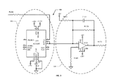
次に図1及び図3を参照すると、一態様では、減衰済みシングルエンデッド電圧信号を動的にスケーリングする第2の回路108は、スケーリング演算増幅器回路304を使用して、減衰済みシングルエンデッド電圧信号を動的にスケーリングする第2の回路108であり、スケーリング演算増幅器回路304は、FPGA又はデジタルプロセッサ110によって制御されるデジタルポテンショメータ302を有する。FPGA又はデジタルプロセッサ110は、上述のアルゴリズムに従って減衰済みシングルエンデッド電圧信号を動的にスケーリングするデジタルポテンショメータ302に入力を与える。一態様では、FPGA又はデジタルプロセッサ110は、減衰済みシングルエンデッド電圧信号のデジタル表現をADC112から受信し、速度信号を速度センサ116から受信し、スケーリング係数と減衰済みシングルエンデッド電圧レベルとの積が最大入力信号電圧以下になるようにデジタルポテンショメータ302を自動的に調節することにより、減衰済みシングルエンデッド電圧信号をスケーリングする。一態様では、スケーリング係数は1以上であり、例えば、1.0、1.1、1.2、2.0、2.5、10.0などである。別の態様では、スケーリング係数は1未満であり、例えば、0.95、0.90、0.5、0.33、0.10、0.01などである。
1 and 3, in one aspect, the
図3は、本発明の一態様による、減衰済みシングルエンデッド電圧信号を動的にスケーリングすることが可能な回路108の一実施形態の回路図である。一態様では、減衰済みシングルエンデッド電圧信号を動的にスケーリングすることは、スケーリング演算増幅器回路304の出力の信号対ノイズ比が改善されるように、且つ、その出力が、信号のクリッピング又は歪みを発生させるほど大きくならないように、FPGA又はプロセッサ110が、上述のアルゴリズムに従ってデジタルポテンショメータ302を自動的に調節することを含む。一態様では、出力の信号対ノイズ比は最大化される。上述のように、アルゴリズムは、減衰済みシングルエンデッド電圧信号をスケーリングする際に、ターゲット104(又はセンサ102)の速度を考慮する。一態様では、デジタルポテンショメータ302の出力がスケーリング演算増幅器回路304に入力されて、スケーリング演算増幅器回路304の出力の動的スケーリングが行われる。限定ではない一例として、デジタルポテンショメータ302は更に、値が1マイクロファラドであるキャパシタC124を含んでよい。又、限定ではない一例として、スケーリング演算増幅器回路304は、R173=49.9キロオーム、R174=20.0キロオーム、R175=10.0キロオーム、R165=4.99キロオーム、及びC121=5.6ピコファラドの値を有するレジスタ及びキャパシタを含んでよい。一態様では、デジタルポテンショメータ302は、(例えば、Analog Devices,Inc.(マサチューセッツ州ノーウッド)から入手可能な)単一チャネル、1024ポジションのデジタルポテンショメータであってよい。一態様では、デジタルポテンショメータ302は、Analog Devices,Inc.のAD5293型デジタルポテンショメータであってよい。図3の回路は、限定ではない例として示したものであるが、同じ機能を別の回路で実現することも可能であることを理解されたい。
FIG. 3 is a circuit diagram of one embodiment of a
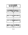
図4は、速度信号を用いて磁気センサの動的自動利得制御を行うために実施される操作を示している。ステップ402で、センサから交流差動電圧信号を受信する。一態様では、センサは受動磁気センサである。一態様では、センサは可変磁気抵抗センサである。交流差動電圧信号の振幅は、ターゲットの速度変化に応じて変化する。例えば、センサがタービンのブレード台を監視している場合、機械が毎分ゼロ回転(0rpm)から動作速度(例えば、3600rpm)まで立ち上がるにつれて、センサからの交流差動電圧信号の振幅が増加する。これは、センサから発生する交流差動電圧信号が、ターゲットの材料組成、センサとターゲットとの間のギャップ、及びターゲットがセンサのそばを通過する(又はセンサがターゲットのそばを通過する)際の速度に関連しているためである。一態様では、ターゲットはタービンブレードである。ステップ404で、交流差動電圧信号を減衰済みシングルエンデッド電圧信号に変換する。一態様では、交流差動電圧信号は、最大ピークツーピーク値を有しており、交流差動電圧信号を減衰済みシングルエンデッド電圧信号に変換することは、最大ピークツーピーク値に対する減衰済み最大電圧の比を交流差動電圧信号に乗じることを含む。一態様では、交流差動電圧信号の最大ピークツーピーク値は、250ボルトピークツーピークであってよく、減衰済みシングルエンデッド電圧信号の減衰済み最大電圧は、30ボルトピークツーピークであってよい。一態様では、交流差動電圧信号を減衰済みシングルエンデッド電圧信号に変換することは、減衰済みシングルエンデッド電圧信号が減衰済み最大電圧以下になるように、交流差動電圧信号を固定量だけ減衰させることを含む。一態様では、交流差動電圧信号を減衰済みシングルエンデッド電圧信号に変換することは、抵抗分割器を用いて交流差動電圧信号を分割することと、シングルエンデッド出力を有する演算増幅器に差動入力を与えることと、を含む。ステップ406で、速度センサから速度信号を受信する。一態様では、速度信号は、磁気センサに対するターゲットの現在の速度を示す。一態様では、速度信号は、ターゲットに対する磁気センサの現在の速度を示す。ステップ408で、スケーリング係数を決定する。一態様では、スケーリング係数は、速度入力と、減衰済みシングルエンデッド電圧信号のデジタル表現とから決定される。一態様では、スケーリング係数は、速度信号に応じて選択され、且つ、スケーリングされた減衰済みシングルエンデッド電圧信号の信号対ノイズ比を最大化するように選択される。ステップ410で、減衰済みシングルエンデッド電圧信号にスケーリング係数を乗じることにより、減衰済みシングルエンデッド電圧信号を動的にスケーリングする。一態様では、減衰済みシングルエンデッド電圧信号にスケーリング係数を乗じることによって減衰済みシングルエンデッド電圧信号を動的にスケーリングすることは、本明細書に記載のように、スケーリング係数と減衰済みシングルエンデッド電圧信号との積が最大入力信号電圧以下になるようにスケーリング係数を選択することを含む。一態様では、速度信号に応じてスケーリング係数を選択することは、ターゲットの最大速度に対するターゲットの現在の速度の比に応じて前記スケーリング係数を選択することを含む。一態様では、最大入力信号電圧は、6.5ボルトピークツーピークである。一態様では、減衰済みシングルエンデッド電圧レベルにスケーリング係数を乗じることによって減衰済みシングルエンデッド電圧信号を動的にスケーリングすることは、フィールドプログラマブルゲートアレイ(FPGA)又はデジタルプロセッサによって制御されるデジタルポテンショメータを有するスケーリング演算増幅器回路を用いて減衰済みシングルエンデッド電圧信号を動的にスケーリングすることを含む。一態様では、FPGA又はデジタルプロセッサは、減衰済みシングルエンデッド電圧信号のデジタル表現と、速度信号とを受信し、スケーリング係数と減衰済みシングルエンデッド電圧レベルとの積が最大入力信号電圧以下になるようにデジタルポテンショメータを調節することにより、減衰済みシングルエンデッド電圧信号を動的にスケーリングする。一態様では、スケーリング係数は1以上であり、例えば、1.0、1.1、1.2、2.0、2.5、10.0などである。別の態様では、スケーリング係数は1未満であり、例えば、0.95、0.90、0.5、0.33、0.10、0.01などである。
FIG. 4 illustrates the operations performed to perform dynamic automatic gain control of the magnetic sensor using the velocity signal. In
上述のシステムは、複数のユニット(例えば、FPGA又はデジタルプロセッサ110など)を含むものとして示した。当業者であれば理解されるように、これは機能の説明であり、個々の機能は、ソフトウェア、ハードウェア、又はソフトウェアとハードウェアとの組み合わせにより実現可能である。FPGA又はプロセッサ110のようなユニットは、ソフトウェア、ハードウェア、又はソフトウェアとハードウェアの組み合わせであってよい。これらのユニットは、図5に示された、後述のデジタルポテンショメータ制御ソフトウェア506を含んでよい。一例示的態様では、これらのユニットは、図5に示された、後述のコンピュータ501を含んでよい。一態様では、コンピュータ501のプロセッサ503を用いて、コンピュータ実行可能コードの形で具体化された上述のアルゴリズムを実行し、本明細書に記載のデジタルポテンショメータ302を制御することが可能である。
The system described above is shown as including multiple units (eg, FPGA or digital processor 110). As will be appreciated by those skilled in the art, this is a functional description, and individual functions can be realized by software, hardware, or a combination of software and hardware. A unit such as the FPGA or
図5は、本開示の方法を実行するための一例示的動作環境を示すブロック図である。この例示的動作環境は、あくまで動作環境の一例であって、動作環境アーキテクチャの用途又は機能性の範囲に関して何らかの制限を与えるものではない。又、動作環境は、この例示的動作環境に示されたいずれかのコンポーネント又はコンポーネントの組み合わせに関連する従属性又は要件を有するものとして解釈されるべきではない。 FIG. 5 is a block diagram illustrating an exemplary operating environment for performing the methods of the present disclosure. This exemplary operating environment is merely an example of an operating environment and does not impose any restrictions on the scope of use or functionality of the operating environment architecture. Neither should the operating environment be interpreted as having any dependency or requirement relating to any one or combination of components illustrated in the exemplary operating environment.
本発明の方法及びシステムは、他の様々な汎用又は専用のコンピューティングシステム環境又は構成とともに動作可能であってよい。本システム及び本方法との使用に好適となりうる周知のコンピューティングシステム、環境、及び/又は構成として、例えば、埋め込み処理ユニット、パーソナルコンピュータ、サーバコンピュータ、ラップトップ装置、マルチプロセッサシステムなどがあるが、これらに限定されない。更なる例として、機械監視システム、プログラマブル民生用電子機器、ネットワークPC、ミニコンピュータ、メインフレームコンピュータ、スマートメータ、スマートグリッドコンポーネント、上述のシステム又は装置のいずれかを含む分散コンピューティング環境、FPGAなどがある。 The methods and systems of the present invention may be operational with various other general purpose or special purpose computing system environments or configurations. Known computing systems, environments, and / or configurations that may be suitable for use with the system and method include, for example, embedded processing units, personal computers, server computers, laptop devices, multiprocessor systems, etc. It is not limited to these. Further examples include machine monitoring systems, programmable consumer electronics, network PCs, minicomputers, mainframe computers, smart meters, smart grid components, distributed computing environments including any of the systems or devices described above, FPGAs, etc. is there.
本開示の方法及びシステムの処理は、ソフトウェアコンポーネントによって実行可能である。本開示のシステム及び方法は、1つ以上のコンピュータ又は他の装置によって実行されるコンピュータ実行可能命令(プログラムモジュールなど)の一般的コンテキストの形で説明できる。一般に、プログラムモジュールは、特定のタスクを実行したり、特定の抽象データ型を実装したりするコンピュータコード、ルーチン、プログラム、オブジェクト、コンポーネント、データ構造体などを含む。本開示の方法は又、通信ネットワークを介してリンクされている複数のリモート処理装置によってタスクが実行される、グリッドベースの分散コンピューティング環境においても実施可能である。分散コンピューティング環境では、プログラムモジュールは、ローカルとリモートの両方のコンピュータ記憶媒体(メモリ記憶装置を含む)に配置可能である。 The processes of the disclosed method and system can be performed by software components. The systems and methods of the present disclosure can be described in the general context of computer-executable instructions (such as program modules) executed by one or more computers or other devices. Generally, program modules include computer code, routines, programs, objects, components, data structures, etc. that perform particular tasks or implement particular abstract data types. The disclosed method can also be practiced in grid-based distributed computing environments where tasks are performed by multiple remote processing devices that are linked through a communications network. In a distributed computing environment, program modules can be located in both local and remote computer storage media (including memory storage devices).
更に、当業者であれば理解されるように、本明細書に開示のシステム及び方法は、コンピュータ501の形の汎用コンピューティング装置を用いて実装可能である。コンピュータ501のコンポーネントとしては、限定ではなく、1つ以上のプロセッサ又は処理ユニット503、システムメモリ512、及びプロセッサ503を始めとする各種システムコンポーネントをシステムメモリ512と結合するシステムバス513があってよい。処理ユニット503が複数ある場合、本システムは、並列コンピューティングを利用することが可能である。
Further, as will be appreciated by those skilled in the art, the systems and methods disclosed herein can be implemented using a general purpose computing device in the form of a computer 501. The components of computer 501 may include, but are not limited to, one or more processors or
システムバス513は、いくつかの可能なタイプのバス構造のうちの1つ以上を表しており、可能なタイプのバス構造には、メモリバス又はメモリコントローラ、ペリフェラルバス、アクセラレーテッドグラフィックスポート、及び各種バスアーキテクチャのいずれかを用いたプロセッサバス又はローカルバスが含まれる。例えば、そのようなアーキテクチャとして、ISA(Industry Standard Architecture)バス、MCA(Micro Channel Architecture)バス、EISA(Enhanced ISA)バス、VESA(Video Electronics Standards Association)ローカルバス、AGP(Accelerated Graphics Port)バス、並びに、PCI(Peripheral Component Interconnects)、PCI−Expressバス、PCMCIA(Personal Computer Memory Card Industry Association)、USB(Universal Serial Bus)などがあってよい。バス513、及び本明細書で指定されているすべてのバスは又、有線又は無線のネットワーク接続を用いて実装可能であり、プロセッサ503、大容量記憶装置504、オペレーティングシステム505、デジタルポテンショメータ制御ソフトウェア506、制御アルゴリズムデータ507(例えば、ValueL及びValueUの値、増幅又は減衰の設定、その他)、ネットワークアダプタ508、システムメモリ512、入出力インタフェース510、ディスプレイアダプタ509、ディスプレイ装置511、及び人間機械インタフェース502を含むサブシステムのそれぞれが、物理的に互いに離れた場所にあって、この形のバスを通じて接続されている1つ以上のリモートコンピューティング装置又はクライアント514a、b、cに収容可能であり、実質的に、完全な分散システム又は分散アーキテクチャが実装される。
The
コンピュータ501は、典型的には、様々なコンピュータ可読媒体を含んでいる。例示的な可読媒体としては、持続性であってコンピュータ501からのアクセスが可能な任意の入手可能媒体であってよく、限定ではない例として、揮発性及び不揮発性媒体の両方、リムーバブル及び非リムーバブル媒体の両方がある。システムメモリ512は、揮発性メモリ(ランダムアクセスメモリ(RAM)など)及び/又は不揮発性メモリ(読み出し専用メモリ(ROM)など)の形でコンピュータ可読媒体を含む。システムメモリ512は、典型的には、制御アルゴリズムデータ507などのデータ及び/又はオペレーティングシステム505などのプログラムモジュールと、処理ユニット503から直接アクセス可能な、且つ/又は、処理ユニット503によって現在操作されているデジタルポテンショメータ制御ソフトウェア506とを収容している。
Computer 501 typically includes a variety of computer readable media. Exemplary readable media may be any available media that is persistent and accessible by computer 501 and includes, by way of non-limiting example, both volatile and non-volatile media, removable and non-removable media. There are both media. The
別の態様では、コンピュータ501は、他の持続的、リムーバブル/非リムーバブル、揮発性/不揮発性コンピュータ記憶媒体を含んでもよい。例えば、図5は、大容量記憶装置504を示しており、大容量記憶装置504は、コンピュータコード、コンピュータ可読命令、データ構造体、プログラムモジュール、及び他のコンピュータ501用データの不揮発性記憶を行うことが可能である。限定ではない例として、大容量記憶媒体504は、ハードディスク、リムーバブル磁気ディスク、リムーバブル光ディスク、磁気カセットなどの磁気記憶装置、フラッシュメモリカード、CD−ROM、デジタル多用途ディスク(DVD)などの光記憶装置、ランダムアクセスメモリ(RAM)、読み出し専用メモリ(ROM)、電気的消去可能プログラム可能読み出し専用メモリ(EEPROM)などであってよい。 In another aspect, the computer 501 may include other persistent, removable / non-removable, volatile / nonvolatile computer storage media. For example, FIG. 5 illustrates a mass storage device 504 that performs non-volatile storage of computer code, computer readable instructions, data structures, program modules, and other computer 501 data. It is possible. As a non-limiting example, the mass storage medium 504 is a hard disk, a removable magnetic disk, a removable optical disk, a magnetic storage device such as a magnetic cassette, an optical storage device such as a flash memory card, a CD-ROM, or a digital versatile disk (DVD). A random access memory (RAM), a read only memory (ROM), an electrically erasable programmable read only memory (EEPROM), and the like.
オプションで、任意の数のプログラムモジュールを大容量記憶媒体504に記憶させることが可能であり、例えば、オペレーティングシステム505やデジタルポテンショメータ制御ソフトウェア506などを記憶させることが可能である。オペレーティングシステム505及びデジタルポテンショメータ制御ソフトウェア506のそれぞれ(又はこれらの何らかの組み合わせ)は、プログラミング及びデジタルポテンショメータ制御ソフトウェア506の各要素を含むことが可能である。制御アルゴリズムデータ507も、大容量記憶装置504に記憶させることが可能である。制御アルゴリズムデータ507は、当該技術分野において周知の1種類以上のデータベースのいずれかに格納可能である。そのようなデータベースとしては、例えば、DB2(登録商標)(IBM Corporation、ニューヨーク州アーモンク)、Microsoft(登録商標) Access、Microsoft(登録商標) SQL Server(Microsoft Corporation、ワシントン州ベルビュー)、Oracle(登録商標)、mySQL、PostgreSQLなどがある。これらのデータベースは、集中化しても、複数システムにまたがって分散してもよい。
Optionally, any number of program modules can be stored in the mass storage medium 504, such as an
別の態様では、ユーザは、入力装置(図示せず)からコンピュータ501にコマンド及び情報を入力することが可能である。そのような入力装置の限定ではない例として、キーボード、ポインティングデバイス(例えば、「マウス」)、マイクロホン、ジョイスティック、スキャナ、触覚入力装置(手袋や他の身体を覆うもの)などがある。これら及び他の入力装置は、システムバス513に結合された人間機械インタフェース502を介して処理ユニット503に接続可能であるが、他のインタフェース及びバス構造によっても接続可能であり、例えば、パラレルポート、ゲームポート、IEEE 1394ポート(ファイヤワイヤとも呼ぶ)、シリアルポート、又はUSB(ユニバーサルシリアルバス)などにより接続可能である。
In another aspect, a user can enter commands and information into the computer 501 from an input device (not shown). Non-limiting examples of such input devices include keyboards, pointing devices (eg, “mouse”), microphones, joysticks, scanners, tactile input devices (those that cover gloves and other bodies), and the like. These and other input devices can be connected to the
更に別の態様では、ディスプレイアダプタ509などのインタフェースを介して、ディスプレイ装置511をシステムバス513に接続することも可能である。コンピュータ501は、複数のディスプレイアダプタ509を有することが可能であり、且つ、コンピュータ501は、複数のディスプレイ装置511を有することが可能であるとしている。例えば、ディスプレイ装置は、モニタ、LCD(液晶ディスプレイ)、又はプロジェクタであってよい。ディスプレイ装置511に加えて、他の出力ペリフェラル装置として、入出力インタフェース510を介してコンピュータ501と接続可能な、スピーカ(図示せず)やプリンタ(図示せず)などのコンポーネントを含んでもよい。センサ及び/又はトランスデューサ(図示せず)からの入力も、入出力インタフェース510を通してプロセッサ503に接続してよい。本方法の任意のステップ及び/又は結果を、任意の形で出力装置に出力することが可能である。このような出力は、限定ではなくテキスト、グラフィックス、アニメーション、音声、触感などを含む、任意の視覚的表現形式であってよい。
In yet another aspect, the
コンピュータ501は、ネットワーク環境において、1つ以上のリモートコンピューティング装置又はクライアント514a、b、cとの論理接続を用いて動作可能である。例えば、リモートコンピューティング装置514は、パーソナルコンピュータ、ポータブルコンピュータ、サーバ、ルータ、ネットワークコンピュータ、スマートメータ、ベンダ又は製造元のコンピューティング装置、スマートグリッドコンポーネント、ピア装置又は他の共通ネットワークノードなどであってよい。コンピュータ501とリモートコンピューティング装置又はクライアント514a、b、cとの間の論理接続は、ローカルエリアネットワーク(LAN)及び一般的なワイドエリアネットワーク(WAN)を介して可能である。そのようなネットワーク接続は、ネットワークアダプタ508を通して可能である。ネットワークアダプタ508は、有線環境でも無線環境でも実装可能である。そのようなネットワーキング環境は、オフィス、企業規模コンピュータネットワーク、イントラネット、及び他のネットワーク515(インターネットなど)においては普通に存在するものである。
Computer 501 is operable in a network environment using logical connections with one or more remote computing devices or clients 514a, b, c. For example, the remote computing device 514 may be a personal computer, portable computer, server, router, network computer, smart meter, vendor or manufacturer computing device, smart grid component, peer device or other common network node, etc. . Logical connections between computer 501 and remote computing devices or clients 514a, b, c are possible via a local area network (LAN) and a general wide area network (WAN). Such a network connection is possible through the
本明細書では、説明のために、アプリケーションプログラム及び他の実行可能プログラムコンポーネント(オペレーティングシステム505など)を、個別のブロックとして示しているが、そのようなプログラム及びコンポーネントが、様々なタイミングで、コンピューティング装置501の様々な記憶コンポーネントに存在して、コンピュータの1つ以上のデータプロセッサによって実行されることは周知のとおりである。デジタルポテンショメータ制御ソフトウェア506の実装は、何らかの形のコンピュータ可読媒体に格納可能であり、或いは、何らかの形のコンピュータ可読媒体同士の間で送信可能である。本開示のどの方法も、コンピュータ可読媒体上に具体化されたコンピュータ可読命令によって実行可能である。コンピュータ可読媒体は、コンピュータからのアクセスが可能な、任意の入手可能媒体であってよい。限定ではない例として、コンピュータ可読媒体は、「コンピュータ記憶媒体」及び「通信媒体」を含んでよい。「コンピュータ記憶媒体」は、コンピュータ可読命令、データ構造体、プログラムモジュール、又は他のデータのような情報を記憶するための任意の方法又は技術において実装される揮発性及び不揮発性、リムーバブル及び非リムーバブルの媒体を含む。例示的なコンピュータ記憶媒体は、限定ではなく、RAM、ROM、EEPROM、フラッシュメモリなどのメモリ装置、CD−ROM、デジタル多用途ディスク(DVD)などの光記憶装置、磁気カセット、磁気テープ、磁気ディスク記憶装置などの磁気記憶装置、又は他の任意の、所望の情報を記憶することが可能であってコンピュータからのアクセスが可能である媒体などを含む。
For purposes of illustration, application programs and other executable program components (such as operating system 505) are shown as separate blocks for purposes of illustration, but such programs and components may be computed at various times on a computer. As is well known, it resides in various storage components of the storage device 501 and is executed by one or more data processors of the computer. An implementation of the digital
本方法及びシステムでは、機械学習や反復学習のような人工知能技術を採用することが可能である。そのような技術の限定ではない例として、エキスパートシステム、事例に基づく推論、ベイジアンネットワーク、行動ベースAI、ニューラルネットワーク、ファジーシステム、進化的計算法(例えば、遺伝的アルゴリズム)、群知能(例えば、アントアルゴリズム)、ハイブリッドインテリジェントシステム(例えば、ニューラルネットワークを通じて生成されるエキスパート推論規則、又は統計的学習から得られるプロダクション規則)などがある。 The method and system can employ artificial intelligence techniques such as machine learning and iterative learning. Non-limiting examples of such techniques include expert systems, case-based reasoning, Bayesian networks, behavior-based AI, neural networks, fuzzy systems, evolutionary computation (eg, genetic algorithms), swarm intelligence (eg, Ant Algorithms), hybrid intelligent systems (eg, expert inference rules generated through neural networks, or production rules derived from statistical learning).
以下の実施例は、当業者に向けて、本明細書において特許請求されるシステム、物品、装置、及び/又は方法の構成方法及び評価方法についての完全な開示及び説明を提供することを意図したものであるとともに、単に例示的であることを意図したものであって、本方法及びシステムの範囲を限定することを意図したものではない。数値については正確であるように努めたが、多少の誤差や偏差は容赦されたい。 The following examples are intended to provide those of ordinary skill in the art with a complete disclosure and description of how the systems, articles, devices, and / or methods claimed herein are constructed and evaluated. And is intended to be exemplary only and is not intended to limit the scope of the method and system. I tried to be accurate about the numbers, but forgive some errors and deviations.
限定ではない一例示的応用では、本発明の実施形態をタービンブレード監視システムで使用することが可能である(ただし、本発明の範囲内では他の用途も予期されている)。例えば、本明細書に記載のセンサ102を用いて、ガスタービン台におけるタービンブレードの到着時刻(TOA)の変化を検出することが可能である。TOAの変化は、ブレードの故障の兆候である可能性がある。
In one non-limiting exemplary application, embodiments of the present invention can be used in turbine blade monitoring systems (although other applications are contemplated within the scope of the present invention). For example, the
工業用ガスタービンにおいては、回転子の完全破壊につながる、圧縮機のブレードの「遊離」事象が問題であった。これらの事象は、ブレードにおいて始まった疲労亀裂が原因であり、これが伝搬して最終的な破壊を引き起こす。ブレードが遊離すると、通常は、回転子の大規模破壊が起こる。壊滅的な故障が発生する前にこの問題を検出するために、ブレード監視システムは、ブレードの到着時刻(TOA)データを計算及び記憶して、工業ガスタービンエンジンの圧縮機台において発達中の亀裂を検出するように設計された。 In industrial gas turbines, compressor blade “free” events were a problem, leading to complete destruction of the rotor. These events are due to fatigue cracks that have begun in the blade, which propagate and cause final failure. When the blades are released, a large-scale destruction of the rotor usually occurs. In order to detect this problem before a catastrophic failure occurs, the blade monitoring system calculates and stores blade arrival time (TOA) data to develop a crack in the industrial gas turbine engine compressor base. Designed to detect.
ブレード通過測定の基本原理は、ワンスパーターン(once-per-turn)(キーフェーザ)トランスデューサを用いて時刻基準を設定し、その後、列内の各ブレードごとに、そのブレードがブレード通過検出トランスデューサのそばを通過した際のブレードの到着時刻(TOA)を測定することを含む。TOAの動的変化及び静的変化を解析することにより、亀裂の存在を示している可能性のあるブレード共振周波数のずれ及び/又は静的傾斜を検出する。 The basic principle of blade passage measurement is to set a time reference using an once-per-turn (key phasor) transducer, and then for each blade in the row, the blade passes by the blade passage detection transducer. Including measuring the arrival time (TOA) of the blade as it passes. Analysis of TOA dynamic and static changes detects blade resonance frequency shifts and / or static tilts that may indicate the presence of cracks.
機械がゼロから全速まで立ち上がるとセンサはある電圧範囲を突き抜けるため(機械の全速時には、ブレードの先端の速度が音速を超える可能性がある)、立ち上がり時には、低電圧時の信号対ノイズ比を最大化し、高電圧時の歪みのクリッピングを防ぐために、センサの出力のスケーリング(即ち、増幅又は減衰)を行う必要がある。これにより、タービンブレードの健康状態を監視するために、センサ出力を用いてTOAを計算することが可能になる。従って、本明細書に記載のシステム及び方法の実施形態を用いることにより、前述の要件を満たすことが可能である。 When the machine starts up from zero to full speed, the sensor penetrates a certain voltage range (the speed of the blade tip may exceed the speed of sound at full speed of the machine), so at start-up the maximum signal-to-noise ratio at low voltage The output of the sensor needs to be scaled (ie, amplified or attenuated) to prevent distortion clipping at high voltages. This makes it possible to calculate the TOA using the sensor output to monitor the health of the turbine blade. Thus, by using the system and method embodiments described herein, it is possible to meet the aforementioned requirements.
上述のように、且つ、当業者であれば理解されるように、本発明の実施形態は、システム、方法、又はコンピュータプログラム製品として構成可能である。従って、本発明の実施形態を構成する様々な手段は、すべてがハードウェアからなる手段、又はすべてがソフトウェアからなる手段、又はソフトウェアとハードウェアの何らかの組み合わせであってよい。更に、本発明の実施形態は、コンピュータ可読記憶媒体において具体化されたコンピュータ可読プログラム命令(例えば、コンピュータソフトウェア)を有する、コンピュータ可読記憶媒体上のコンピュータプログラム製品の形をとることが可能である。任意の好適な、持続的なコンピュータ可読記憶媒体が利用可能であり、具体的には、ハードディスク、CD−ROM、光記憶装置、又は磁気記憶装置などが利用可能である。 As described above and as will be appreciated by one skilled in the art, embodiments of the present invention can be configured as a system, method, or computer program product. Accordingly, the various means constituting the embodiment of the present invention may be means consisting entirely of hardware, means consisting entirely of software, or some combination of software and hardware. Further, embodiments of the present invention may take the form of a computer program product on a computer-readable storage medium having computer-readable program instructions (eg, computer software) embodied in the computer-readable storage medium. Any suitable persistent computer-readable storage medium can be used, specifically, a hard disk, CD-ROM, optical storage device, magnetic storage device, or the like.
本発明の実施形態を、方法、装置(即ち、システム)、及びコンピュータプログラム製品のブロック図及びフローチャート図を参照しながら説明してきた。ブロック図及びフローチャート図の各ブロック、並びに、ブロック図及びフローチャート図におけるブロック同士の組み合わせは、それぞれ、コンピュータプログラム命令を含む様々な手段によって実装可能であることが理解されよう。これらのコンピュータプログラム命令は、汎用コンピュータ、専用コンピュータ、又は他のプログラム可能データ処理装置(例えば、図5を参照して上述された1つ以上のプロセッサ503)にロードされて、コンピュータ又は他のプログラム可能データ処理装置において実行されるそれらの命令によって、1つ以上のフローチャートブロックで指定される機能を実装する手段が形成されるような、機械を生成することが可能である。
Embodiments of the present invention have been described with reference to block diagrams and flowchart illustrations of methods, apparatus (ie, systems), and computer program products. It will be understood that each block of the block diagrams and flowchart illustrations, and combinations of blocks in the block diagrams and flowchart illustrations, respectively, can be implemented by various means including computer program instructions. These computer program instructions may be loaded into a general purpose computer, special purpose computer, or other programmable data processing device (eg, one or
これらのコンピュータプログラム命令は、持続的なコンピュータ可読メモリに格納することも可能であって、コンピュータ又は他のプログラム可能データ処理装置(例えば、図5の1つ以上のプロセッサ503)を、コンピュータ可読メモリに格納されたそれらの命令によって、1つ以上のフローチャートブロックで指定される機能を実装するコンピュータ可読命令を含む製造物が生成されるように、特定の方法で機能させることが可能である。これらのコンピュータプログラム命令は、コンピュータ又は他のプログラム可能データ処理装置にロードされて、そのコンピュータ又は他のプログラム可能データ処理装置において一連の操作ステップを実行させることも可能であり、これによって、そのコンピュータ又は他のプログラム可能データ処理装置において実行される命令が、1つ以上のフローチャートブロックで指定される機能を実装するステップを与えるように、コンピュータ実装プロセスを生成することが可能である。
These computer program instructions can also be stored in a persistent computer readable memory that stores a computer or other programmable data processing device (eg, one or
従って、ブロック図及びフローチャート図の各ブロックは、本明細書に記載の各機能を実行する手段の組み合わせ、本明細書に記載の各機能を実行するステップの組み合わせ、及び本明細書に記載の各機能を実行するプログラム命令手段をサポートしている。又、ブロック図及びフローチャート図の各ブロック、並びに、ブロック図及びフローチャート図におけるブロック同士の組み合わせは、本明細書に記載の各機能又は各ステップを実行する専用ハードウェアベースのコンピュータシステム、又は専用ハードウェアとコンピュータ命令との組み合わせによって実装可能であることも理解されよう。 Accordingly, each block in the block diagram and the flowchart diagram includes a combination of means for performing each function described in this specification, a combination of steps for performing each function described in this specification, and each of the blocks described in this specification. Supports program instruction means to execute functions. In addition, each block in the block diagram and the flowchart diagram, and a combination of blocks in the block diagram and the flowchart diagram, is a dedicated hardware-based computer system or dedicated hardware that executes each function or each step described in this specification. It will also be understood that it can be implemented by a combination of hardware and computer instructions.
別途明記しない限り、本明細書で説明したいかなる方法も、方法ステップを特定の順番で実施することを要件としていると解釈されるべきではない。従って、方法クレームにおいて実際に、そのステップが辿るべき順序を列挙しているか又は請求項において当該ステップが特定の順序に限定される旨の記述がなされていない限り、順序を示唆するものではない。ステップの構成に関する論理、文法構造又は句読点から導き出される明白な意味合い、本明細書に記載の実施形態の数又はタイプを含めた、考えられるあらゆる非明示的な解釈の根拠についても同じことが言える。 Unless otherwise stated, any method described herein should not be construed as requiring that the method steps be performed in a particular order. Thus, unless the method claims actually list the order in which the steps are to follow or in the claims, the order is not meant to be implied. The same is true for any conceivable basis for implicit interpretation, including the obvious implications derived from the logic, grammatical structure or punctuation regarding the composition of the steps, and the number or type of embodiments described herein.
本明細書を通じて、様々な公報を参照した。これらの公報の開示内容全体が、参照により本明細書に援用され、これによって、本方法及びシステムが関連する最新技術をより完全に記述している。 Throughout this specification, various publications have been referenced. The entire disclosures of these publications are hereby incorporated by reference, thereby more fully describing the state of the art to which the present methods and systems relate.
ここで、本発明のこれらの実施形態に付随した、上記の記述及びこれに関連する図面に示した教示の利益を有する、本発明の多くの改変及びその他の実施形態が、当業者には想到されよう。従って、本発明の実施時形態が、開示された特定の実施形態に限定されることはなく、その改変及びその他の実施形態も、添付の特許請求の範囲に含まれることを意図している。また、上記の説明及び関連する図面では、要素及び/機能の或る例示的な組み合わせのコンテキストにおいて実施形態を記述したが、要素及び/機能の異なる組み合わせも、添付の特許請求の範囲から逸脱することなく、変形形態によって提供可能である。この点において、例えば、以上に明記したものとは異なる要素及び/又は機能の組み合わせも、添付の特許請求の範囲のいずれかに記載のものであることも考えられる。本明細書では、特定の用語を用いたが、これらはあくまでも総称的に説明的な意味で用いられたものであって、限定目的で用いられているのではない。 Many modifications and other embodiments of the invention will now occur to those skilled in the art having the benefit of the teachings presented in the foregoing description and associated drawings accompanying these embodiments of the invention. Let's be done. Therefore, embodiments of the invention are not limited to the specific embodiments disclosed, and modifications and other embodiments are intended to be included within the scope of the appended claims. Also, while the foregoing description and associated drawings describe embodiments in the context of certain exemplary combinations of elements and / or features, different combinations of elements and / or functions also depart from the appended claims. Without modification, it can be provided by a modified form. In this regard, for example, combinations of elements and / or functions that differ from those specified above are also contemplated by any of the appended claims. In the present specification, specific terms are used, but these are used generically in a descriptive sense and not for the purpose of limitation.
102 センサ
104 ターゲット
106 回路
108 第2の回路
110 FPGA又はデジタルプロセッサ
112 アナログデジタル変換器(ADC)
114 回路108の出力
116 速度センサ
202 抵抗分割器
204 シングルエンデッド出力を有する演算増幅器
302 デジタルポテンショメータ
304 スケーリング演算増幅器回路
501 コンピュータ
502 人間機械インタフェース
503 プロセッサユニット
504 大容量記憶装置
505 オペレーティングシステム
506 デジタルポテンショメータ制御ソフトウェア
507 制御アルゴリズムデータ
508 ネットワークアダプタ
509 ディスプレイアダプタ
510 入出力インタフェース
511 ディスプレイ装置
512 システムメモリ
513 システムバス
514 1つ以上のリモートコンピューティング装置又はクライアント
515 ネットワーク
102
114 Output of
Claims (10)
前記交流差動電圧信号を減衰済みシングルエンデッド電圧信号に変換するステップと、
前記ターゲット(104)の現在の速度を示す速度信号を受信するステップと、
前記減衰済みシングルエンデッド電圧信号にスケーリング係数を乗じることによって前記減衰済みシングルエンデッド電圧信号を動的にスケーリングするステップであって、前記スケーリング係数は、前記速度信号に応じて選択され、且つ、前記スケーリングされた減衰済みシングルエンデッド電圧信号の信号対ノイズ比に応じて選択されるステップと、
を含む方法。 Receiving, from the sensor (102), an AC differential voltage signal whose amplitude changes in response to a speed change of the target (104);
Converting the AC differential voltage signal to an attenuated single-ended voltage signal;
Receiving a speed signal indicative of a current speed of the target (104);
Dynamically scaling the attenuated single-ended voltage signal by multiplying the attenuated single-ended voltage signal by a scaling factor, the scaling factor being selected in response to the velocity signal; and Selected as a function of the signal to noise ratio of the scaled attenuated single-ended voltage signal;
Including methods.
前記交流差動電圧信号を受信し、前記交流差動電圧信号を減衰済みシングルエンデッド電圧信号に変換する、第1の回路(106)と、
前記ターゲット(104)の現在の速度を示す速度信号を発生させる速度センサ(116)と、
前記減衰済みシングルエンデッド電圧信号にスケーリング係数を乗じることによって前記減衰済みシングルエンデッド電圧信号を動的にスケーリングする第2の回路(108)であって、前記スケーリング係数は、前記速度信号に応じて選択され、且つ、前記スケーリングされた減衰済みシングルエンデッド電圧信号の信号対ノイズ比に応じて選択される、前記第2の回路(108)と、
を備えるシステム。 A sensor (102) configured to generate an AC differential voltage signal whose amplitude changes in response to a speed change of the target (104);
A first circuit (106) that receives the AC differential voltage signal and converts the AC differential voltage signal to an attenuated single-ended voltage signal;
A speed sensor (116) for generating a speed signal indicative of a current speed of the target (104);
A second circuit (108) for dynamically scaling the attenuated single-ended voltage signal by multiplying the attenuated single-ended voltage signal by a scaling factor, the scaling factor being dependent on the velocity signal; And the second circuit (108) selected in response to a signal-to-noise ratio of the scaled attenuated single-ended voltage signal;
A system comprising:
Applications Claiming Priority (2)
| Application Number | Priority Date | Filing Date | Title |
|---|---|---|---|
| US13/033,234 | 2011-02-23 | ||
| US13/033,234 US8836322B2 (en) | 2011-02-23 | 2011-02-23 | Method and system of a sensor interface having dynamic automatic gain control dependent on speed |
Publications (2)
| Publication Number | Publication Date |
|---|---|
| JP2012173293A true JP2012173293A (en) | 2012-09-10 |
| JP2012173293A5 JP2012173293A5 (en) | 2015-04-09 |
Family
ID=45656260
Family Applications (1)
| Application Number | Title | Priority Date | Filing Date |
|---|---|---|---|
| JP2012033480A Pending JP2012173293A (en) | 2011-02-23 | 2012-02-20 | Method and system for sensor interface having dynamic and automatic gain control function depending on speed |
Country Status (7)
| Country | Link |
|---|---|
| US (1) | US8836322B2 (en) |
| EP (1) | EP2492694B1 (en) |
| JP (1) | JP2012173293A (en) |
| CN (1) | CN102650529A (en) |
| AU (1) | AU2012200971B2 (en) |
| CA (1) | CA2768436C (en) |
| DK (1) | DK2492694T3 (en) |
Families Citing this family (6)
| Publication number | Priority date | Publication date | Assignee | Title |
|---|---|---|---|---|
| US8656761B2 (en) * | 2011-05-27 | 2014-02-25 | General Electric Company | Systems and methods for use in providing a sensor signal independent of ground |
| US8963615B1 (en) | 2013-01-31 | 2015-02-24 | General Electric Company | Automatic bipolar signal switching |
| CN103647913A (en) * | 2013-12-24 | 2014-03-19 | 中国科学院半导体研究所 | Field programmable gate array (FPGA) based multichannel high-speed image data acquisition and storage system |
| WO2017068418A1 (en) * | 2015-10-20 | 2017-04-27 | Analog Devices Global | Jle 15 |
| CN110832427B (en) * | 2017-04-14 | 2021-05-04 | 惠普发展公司,有限责任合伙企业 | Input power scaling for power supply devices |
| FR3067889B1 (en) * | 2017-06-14 | 2019-06-28 | Safran Aircraft Engines | METHOD FOR MEASURING ROTATIONAL SPEED OF A TURBOMACHINE TREE TAKING ACCOUNT OF MEASUREMENT NOISE |
Citations (5)
| Publication number | Priority date | Publication date | Assignee | Title |
|---|---|---|---|---|
| JP2003240601A (en) * | 2002-01-29 | 2003-08-27 | Goodrich Pump & Engine Control Systems Inc | System and method for processing signal |
| JP2005106761A (en) * | 2003-10-02 | 2005-04-21 | Bridgestone Corp | Method and apparatus for measuring elongation of conveyor belt |
| JP2005308743A (en) * | 2004-04-16 | 2005-11-04 | General Electric Co <Ge> | Capacitive sensor and method for non-contact measuring of gap and dielectric medium |
| JP2007525673A (en) * | 2004-06-16 | 2007-09-06 | エーエムアイ セミコンダクター インク | Reactive sensor with compensation supply module using compensation based on Pad 'approximation |
| WO2010025017A1 (en) * | 2008-08-29 | 2010-03-04 | General Electric Company | System and method for sensing the periodic position of an object |
Family Cites Families (11)
| Publication number | Priority date | Publication date | Assignee | Title |
|---|---|---|---|---|
| GB1090143A (en) * | 1965-04-07 | 1967-11-08 | Hawker Siddeley Dynamics Ltd | Improvements in or relating to electrical control systems for engines |
| US5510706A (en) * | 1994-02-22 | 1996-04-23 | Delco Electronics Corporation | Differential to single-ended conversion circuit for a magnetic wheel speed sensor |
| US5477142A (en) | 1994-02-22 | 1995-12-19 | Delco Electronics Corporation | Variable reluctance sensor interface using a differential input and digital adaptive control |
| JP3223750B2 (en) * | 1995-03-31 | 2001-10-29 | 株式会社日立製作所 | Power control power amplifier, wireless communication terminal and wireless communication base station |
| DE19710359B4 (en) * | 1997-03-13 | 2006-05-11 | Robert Bosch Gmbh | Device for determining a movement quantity with automatic tray factor tracking |
| US6040692A (en) * | 1998-05-18 | 2000-03-21 | Delco Electronics Corporaiton | Variable attenuation circuit for a differential variable reluctance sensor using current mode |
| US6133728A (en) | 1998-05-18 | 2000-10-17 | Delco Electronics Corporation | Current mode differential to single-ended conversion circuit for a magnetic wheel speed sensor |
| US6674279B2 (en) * | 2002-05-09 | 2004-01-06 | Delphi Technologies, Inc. | Variable attenuation circuit for a differential variable reluctance sensor with enhanced initial threshold accuracy |
| US7498886B2 (en) * | 2006-01-27 | 2009-03-03 | Via Technologies, Inc. | Clock distribution system and method thereof |
| US7739014B2 (en) * | 2006-08-30 | 2010-06-15 | Ford Global Technolgies | Integrated control system for stability control of yaw, roll and lateral motion of a driving vehicle using an integrated sensing system to determine a final linear lateral velocity |
| US8346100B2 (en) * | 2009-10-12 | 2013-01-01 | Avago Technologies Fiber Ip (Singapore) Pte. Ltd | Apparatus and method for monitoring received optical power in an optical receiver over a wide range of received power with high accuracy |
-
2011
- 2011-02-23 US US13/033,234 patent/US8836322B2/en active Active
-
2012
- 2012-02-16 CA CA2768436A patent/CA2768436C/en active Active
- 2012-02-20 AU AU2012200971A patent/AU2012200971B2/en active Active
- 2012-02-20 JP JP2012033480A patent/JP2012173293A/en active Pending
- 2012-02-21 DK DK12156300T patent/DK2492694T3/en active
- 2012-02-21 EP EP20120156300 patent/EP2492694B1/en active Active
- 2012-02-23 CN CN2012100576464A patent/CN102650529A/en active Pending
Patent Citations (5)
| Publication number | Priority date | Publication date | Assignee | Title |
|---|---|---|---|---|
| JP2003240601A (en) * | 2002-01-29 | 2003-08-27 | Goodrich Pump & Engine Control Systems Inc | System and method for processing signal |
| JP2005106761A (en) * | 2003-10-02 | 2005-04-21 | Bridgestone Corp | Method and apparatus for measuring elongation of conveyor belt |
| JP2005308743A (en) * | 2004-04-16 | 2005-11-04 | General Electric Co <Ge> | Capacitive sensor and method for non-contact measuring of gap and dielectric medium |
| JP2007525673A (en) * | 2004-06-16 | 2007-09-06 | エーエムアイ セミコンダクター インク | Reactive sensor with compensation supply module using compensation based on Pad 'approximation |
| WO2010025017A1 (en) * | 2008-08-29 | 2010-03-04 | General Electric Company | System and method for sensing the periodic position of an object |
Also Published As
| Publication number | Publication date |
|---|---|
| US8836322B2 (en) | 2014-09-16 |
| CA2768436C (en) | 2018-07-03 |
| AU2012200971A1 (en) | 2012-09-06 |
| DK2492694T3 (en) | 2014-02-24 |
| EP2492694A1 (en) | 2012-08-29 |
| CA2768436A1 (en) | 2012-08-23 |
| AU2012200971B2 (en) | 2015-01-22 |
| CN102650529A (en) | 2012-08-29 |
| US20120212277A1 (en) | 2012-08-23 |
| EP2492694B1 (en) | 2013-12-25 |
Similar Documents
| Publication | Publication Date | Title |
|---|---|---|
| JP2012211581A (en) | Method and system of sensor interface having dynamic automatic gain control | |
| JP2012173293A (en) | Method and system for sensor interface having dynamic and automatic gain control function depending on speed | |
| JP2012120165A (en) | Method and system for detection of machine operation state for monitoring purposes | |
| Qu et al. | Complex frequency identification using real modal shapes for a structure with proportional damping | |
| JP2013213817A (en) | Systems and methods of identifying types of faults | |
| Liu et al. | A review of modeling and diagnostic techniques for eccentricity fault in electric machines | |
| CN108361079B (en) | Rotor vibration control method and control device | |
| JP2015102402A (en) | Turbine blade vibration displacement evaluation method and turbine blade vibration displacement evaluation apparatus | |
| WO2012099022A1 (en) | Transient recovery voltage measuring device, transient recovery voltage measuring method, and transient recovery voltage measuring program | |
| JP2013033477A (en) | Computing device and methods for presenting data to identify faults within power systems | |
| Atta et al. | Adaptive scheme for detecting induction motor incipient broken bar faults at various load and inertia conditions | |
| US20180276322A1 (en) | Failure diagnosis apparatus, monitoring apparatus, failure diagnosis method and recording medium | |
| Guo et al. | Fault diagnosis for sensors in a class of nonlinear systems | |
| Murray et al. | Detection of rotor forced response vibrations using stationary pressure transducers in a multistage axial compressor | |
| WO2021146208A1 (en) | Adaptive voltage threshold for turbine engine | |
| CN109084891A (en) | A kind of rotary body noise measuring system and test method based on stress variation | |
| Zhong et al. | Demagnetization Fault diagnosis for magnetically suspended PMSM using rotor displacement signals | |
| Schulze et al. | Experimental examination of an axial compressor as a basis for an active stall avoidance system | |
| WO2023132235A1 (en) | Vibration monitoring device, supercharger, and vibration monitoring method | |
| Bajic et al. | Multidimensional vibro-acoustical diagnostics of cavitation: theory and illustration on a Kaplan turbine | |
| Wang et al. | Chaotic Analysis and Machine Learning Diagnosis of Herringbone-grooved Journal Gas Bearing System | |
| Geng et al. | Analysis method of MSCSG rotor deflection signal based on windowed interpolation FFT | |
| CN106124797A (en) | Drift compensation device, method and the speed probe of agitator | |
| Jixing et al. | Study on detection of blade imbalance for DFIG WTS based on spectrum analysis of Hilbert modulus | |
| Bueno et al. | Flywheel sizing and analysis of coefficient fluctuation based on the crank kinematic free response to a torque pulse input |
Legal Events
| Date | Code | Title | Description |
|---|---|---|---|
| A521 | Written amendment |
Free format text: JAPANESE INTERMEDIATE CODE: A523 Effective date: 20150218 |
|
| A621 | Written request for application examination |
Free format text: JAPANESE INTERMEDIATE CODE: A621 Effective date: 20150218 |
|
| A977 | Report on retrieval |
Free format text: JAPANESE INTERMEDIATE CODE: A971007 Effective date: 20151214 |
|
| A131 | Notification of reasons for refusal |
Free format text: JAPANESE INTERMEDIATE CODE: A131 Effective date: 20151222 |
|
| A02 | Decision of refusal |
Free format text: JAPANESE INTERMEDIATE CODE: A02 Effective date: 20160517 |