JP2012172632A - Glow plug control device, and method for manufacturing the same - Google Patents
Glow plug control device, and method for manufacturing the same Download PDFInfo
- Publication number
- JP2012172632A JP2012172632A JP2011037405A JP2011037405A JP2012172632A JP 2012172632 A JP2012172632 A JP 2012172632A JP 2011037405 A JP2011037405 A JP 2011037405A JP 2011037405 A JP2011037405 A JP 2011037405A JP 2012172632 A JP2012172632 A JP 2012172632A
- Authority
- JP
- Japan
- Prior art keywords
- glow plug
- cavity
- molding material
- control device
- insert
- Prior art date
- Legal status (The legal status is an assumption and is not a legal conclusion. Google has not performed a legal analysis and makes no representation as to the accuracy of the status listed.)
- Granted
Links
- 238000000034 method Methods 0.000 title claims abstract description 26
- 238000004519 manufacturing process Methods 0.000 title claims abstract description 22
- 239000012778 molding material Substances 0.000 claims abstract description 115
- 230000020169 heat generation Effects 0.000 claims abstract description 9
- 230000007423 decrease Effects 0.000 claims description 18
- 229920005992 thermoplastic resin Polymers 0.000 claims description 16
- 238000000926 separation method Methods 0.000 claims description 14
- 238000009434 installation Methods 0.000 claims description 7
- 238000013459 approach Methods 0.000 claims description 5
- 238000000465 moulding Methods 0.000 abstract description 106
- 238000007493 shaping process Methods 0.000 abstract description 3
- 239000000463 material Substances 0.000 abstract description 2
- 229920005989 resin Polymers 0.000 description 14
- 239000011347 resin Substances 0.000 description 14
- 238000002485 combustion reaction Methods 0.000 description 10
- 238000005429 filling process Methods 0.000 description 10
- 239000013256 coordination polymer Substances 0.000 description 9
- 238000011900 installation process Methods 0.000 description 9
- 230000013011 mating Effects 0.000 description 6
- 229920001187 thermosetting polymer Polymers 0.000 description 6
- 239000004065 semiconductor Substances 0.000 description 5
- 210000000078 claw Anatomy 0.000 description 4
- 230000004048 modification Effects 0.000 description 4
- 238000012986 modification Methods 0.000 description 4
- 101710118890 Photosystem II reaction center protein Ycf12 Proteins 0.000 description 3
- 239000002184 metal Substances 0.000 description 3
- 229910052751 metal Inorganic materials 0.000 description 3
- 229910000881 Cu alloy Inorganic materials 0.000 description 2
- 239000004734 Polyphenylene sulfide Substances 0.000 description 2
- 238000005452 bending Methods 0.000 description 2
- 230000006353 environmental stress Effects 0.000 description 2
- 239000003822 epoxy resin Substances 0.000 description 2
- 239000007769 metal material Substances 0.000 description 2
- 229920001707 polybutylene terephthalate Polymers 0.000 description 2
- 229920000647 polyepoxide Polymers 0.000 description 2
- 229920000069 polyphenylene sulfide Polymers 0.000 description 2
- 239000000758 substrate Substances 0.000 description 2
- 230000004308 accommodation Effects 0.000 description 1
- 239000000919 ceramic Substances 0.000 description 1
- 230000001747 exhibiting effect Effects 0.000 description 1
- 230000005669 field effect Effects 0.000 description 1
- -1 polybutylene terephthalate Polymers 0.000 description 1
- 238000007711 solidification Methods 0.000 description 1
- 230000008023 solidification Effects 0.000 description 1
- 238000003466 welding Methods 0.000 description 1
Images


Abstract
Description
本発明は、グロープラグの発熱を制御するグロープラグ制御装置、及びグロープラグ制御装置を製造する方法に関する。 The present invention relates to a glow plug control device that controls heat generation of a glow plug, and a method for manufacturing the glow plug control device.
従来から、ディーゼル機関の始動性を改善するためのグロープラグの発熱を制御するグロープラグ制御装置が知られている。例えば、特許文献1には、グロープラグの発熱を制御する制御部としての複数のICチップと、これら複数のICチップを収容するモールド樹脂とを備えたグロープラグ通電制御装置が開示されている。特許文献1に開示のグロープラグ通電制御装置では、複数のICチップ及びモールド樹脂等からなる板状のマルチチップモジュールは、樹脂製のハウジングに収容されている。 Conventionally, a glow plug control device for controlling heat generation of a glow plug for improving startability of a diesel engine is known. For example, Patent Document 1 discloses a glow plug energization control device including a plurality of IC chips as a control unit that controls heat generation of a glow plug and a mold resin that accommodates the plurality of IC chips. In the glow plug energization control device disclosed in Patent Document 1, a plate-shaped multichip module made up of a plurality of IC chips and a mold resin is accommodated in a resin housing.
一方、特許文献2には、ICチップ等の半導体集積基板をモールド樹脂に収容した板状のICパッケージを備えるコネクタ付半導体装置が開示されている。特許文献2に開示のコネクタ付き半導体装置では、半導体集積基板を収容したICパッケージは、エポキシ樹脂等の成形材料によって周囲を覆われている。 On the other hand, Patent Document 2 discloses a semiconductor device with a connector including a plate-like IC package in which a semiconductor integrated substrate such as an IC chip is accommodated in a mold resin. In the semiconductor device with a connector disclosed in Patent Document 2, the periphery of the IC package containing the semiconductor integrated substrate is covered with a molding material such as epoxy resin.
さて、本願発明者らは、特許文献1に開示のようなグロープラグ制御装置において、複数のICチップを収容するマルチチップモジュールの周囲を、さらに樹脂等の成形材料によって覆う構成を想到した。この構成では、マルチチップモジュールを金型内のキャビティに収容し、マルチチップモジュールを金型に対して固定する。そして、型締めされた金型内のキャビティにゲートを通じて成形材料を充填することによって、マルチチップモジュールは、周囲を成形材料によって覆われる。 The inventors of the present application have conceived a configuration in which the periphery of a multichip module that accommodates a plurality of IC chips is further covered with a molding material such as a resin in a glow plug control device as disclosed in Patent Document 1. In this configuration, the multichip module is accommodated in the cavity in the mold, and the multichip module is fixed to the mold. Then, by filling the cavity in the clamped mold with the molding material through the gate, the periphery of the multichip module is covered with the molding material.
しかし、上述した構成及び工程において、キャビティに充填される成形材料は、キャビティ内を流動することにより、マルチチップモジュールにおいてキャビティに開口するゲートの開口部と対向する部分に接触する。すると、成形材料は、マルチチップモジュールの接触した部分によって流動を一旦止められてしまう。以上により、成形材料からインサート部に抵抗力が作用する。そのため、マルチチップモジュールを金型に固定しなければ、マルチチップモジュールの周囲を成形材料によって覆うことができなかった。 However, in the above-described configuration and process, the molding material filled in the cavity flows in the cavity, thereby contacting a portion of the multichip module that faces the opening of the gate that opens to the cavity. Then, the molding material is temporarily stopped from flowing by the contacted portion of the multichip module. Thus, a resistance force acts on the insert portion from the molding material. Therefore, unless the multichip module is fixed to the mold, the periphery of the multichip module cannot be covered with the molding material.
本発明は、上記問題点に鑑みてなされたものであって、その目的は、マルチチップモジュール等のインサート部を金型に固定することなく、当該インサート部の周囲を成形材料によって覆うことのできるグロープラグ制御装置及びグロープラグ制御装置の製造方法を提供することである。 The present invention has been made in view of the above problems, and the object thereof is to cover the periphery of the insert portion with a molding material without fixing the insert portion of a multichip module or the like to a mold. To provide a glow plug control device and a method of manufacturing the glow plug control device.
上記目的を達成するために、請求項1に記載の発明では、金型内のキャビティにゲートを通じて充填される成形材料によって周囲を覆われた板状のインサート部と、インサート部に収容され、グロープラグと接続されることによりグロープラグの発熱を制御する制御部と、を備えるグロープラグ制御装置であって、インサート部においてキャビティに開口するゲートの開口部と対向する対向縁部は、開口部に近接するほど板厚の減少する形状であることを特徴とする。 In order to achieve the above object, according to the first aspect of the present invention, there is provided a plate-like insert portion whose periphery is covered with a molding material filled in a cavity in a mold through a gate, and is accommodated in the insert portion. A glow plug control device comprising: a control unit configured to control heat generation of the glow plug by being connected to the plug, wherein an opposing edge facing the opening of the gate opening in the cavity in the insert portion is formed in the opening It is characterized by a shape in which the plate thickness decreases with increasing proximity.
この発明によれば、金型内のキャビティにゲートを通じて充填される成形材料は、キャビティ内を流動することにより、板状に形成されたインサート部において、キャビティに開口するゲートの開口部と対向する対向縁部に接触する。インサート部の対向縁部は、ゲートの開口部に近接するほど板厚の減少する形状である。故に、成形材料は、対向縁部によって流動を止められることなく、対向縁部に沿って円滑に流動し得る。以上により、成形材料からインサート部に作用する抵抗力は、低減される。したがって、インサート部を金型に固定することなく、当該インサート部の周囲を成形材料によって覆ったグロープラグ制御装置を提供することができる。 According to the present invention, the molding material filled in the cavity in the mold through the gate flows in the cavity, thereby facing the opening of the gate opening in the cavity in the plate-shaped insert portion. Touch the opposite edge. The opposing edge portion of the insert portion has a shape in which the plate thickness decreases as it approaches the opening portion of the gate. Therefore, the molding material can smoothly flow along the facing edge without being stopped by the facing edge. As described above, the resistance force acting on the insert portion from the molding material is reduced. Therefore, it is possible to provide a glow plug control device in which the periphery of the insert portion is covered with the molding material without fixing the insert portion to the mold.
請求項2に記載の発明では、対向縁部は、インサート部の板面方向に沿う仮想平面に対して面対称な一対の傾斜面を有することを特徴とする。 The invention according to claim 2 is characterized in that the opposing edge portion has a pair of inclined surfaces which are plane-symmetric with respect to a virtual plane along the plate surface direction of the insert portion.
この発明によれば、対向縁部に沿って流動する成形材料は、インサート部の板厚方向の抵抗力を当該対向縁部に作用させる。この対向縁部の有する一対の傾斜面がインサート部の板面方向に沿う仮想平面に対して面対称であることにより、成形材料によって生じる板厚方向の抵抗力は、互いに相殺し合う。故に、板厚方向におけるインサート部の固定がさらに確実でなくても、インサート部の周囲は、成形材料によって確実に覆われる。 According to this invention, the molding material that flows along the opposing edge causes the resistance in the thickness direction of the insert portion to act on the opposing edge. Since the pair of inclined surfaces of the opposing edge portions are plane-symmetric with respect to a virtual plane along the plate surface direction of the insert portion, the resistance forces in the plate thickness direction generated by the molding material cancel each other. Therefore, even if the insert portion is not more reliably fixed in the thickness direction, the periphery of the insert portion is reliably covered with the molding material.
請求項3に記載の発明では、グロープラグ制御装置は、インサート部の内部にて制御部と接続され、当該インサート部の外部に延出するリード部材と、キャビティ内においてリード部材を保持する保持部材と、をさらに備え、対向縁部の先端部分は、インサート部の板面方向に沿い且つ当該インサート部の板厚方向の中心を通る仮想中心面よりも、保持部材側にずれて位置することを特徴とする。 In the invention according to claim 3, the glow plug control device is connected to the control portion inside the insert portion, and extends to the outside of the insert portion, and a holding member that holds the lead member in the cavity And the distal end portion of the opposite edge portion is positioned so as to be shifted to the holding member side from the virtual center plane passing along the plate surface direction of the insert portion and passing through the center of the insert portion in the plate thickness direction. Features.
この発明によれば、対向縁部の先端部分は、インサート部の板厚方向の中心を通る仮想中心面よりも、保持部材側にずれて位置している。故に、対向縁部に沿って流動する成形材料は、板厚方向において保持部材側に向かう抵抗力をインサート部に作用させる。この抵抗力によって、インサート部の外部に延出するリード部材は、保持部材に向けて押し付けられる。成形材料の抵抗力によって押し付けられたリード部材は、保持部材に確実に保持され得る。したがって、保持部材を金型に固定することによれば、金型へのインサート部の固定が確実でなくても、インサート部の周囲は、成形材料によって確実に覆われる。 According to this invention, the front-end | tip part of an opposing edge part has shifted | deviated and located in the holding member side rather than the virtual center plane passing through the center of the thickness direction of an insert part. Therefore, the molding material that flows along the opposing edge causes the insert portion to exert a resistance force toward the holding member in the plate thickness direction. Due to this resistance force, the lead member extending to the outside of the insert portion is pressed toward the holding member. The lead member pressed by the resistance force of the molding material can be securely held by the holding member. Therefore, by fixing the holding member to the mold, the periphery of the insert part is reliably covered with the molding material even if the insert part is not securely fixed to the mold.
請求項4に記載の発明では、対向縁部は、成形材料としての熱可塑性樹脂と接触することを特徴とする。 The invention according to claim 4 is characterized in that the opposing edge is in contact with a thermoplastic resin as a molding material.
この発明によれば、熱可塑性樹脂は、一般に高い粘度を有している。故に、成形材料としての熱可塑性樹脂と接触する場合、インサート部は、抵抗力を受けることとなる。しかし、板厚の減少する対向縁部の形状によって、成形材料の流動が円滑化されるので、抵抗力の増加は抑制される。以上のように、対向縁部の板厚を減少させることにより抵抗力を低減する作用は、成形材料として粘度の高い熱可塑性樹脂を用いる形態において、特に有効なのである。 According to this invention, the thermoplastic resin generally has a high viscosity. Therefore, when it contacts with the thermoplastic resin as a molding material, an insert part will receive resistance. However, since the flow of the molding material is smoothed by the shape of the opposing edge where the plate thickness decreases, an increase in resistance is suppressed. As described above, the action of reducing the resistance force by reducing the thickness of the opposing edge is particularly effective in the embodiment using the thermoplastic resin having a high viscosity as the molding material.
請求項5に記載の発明では、グロープラグ制御装置は、インサート部の内部にて制御部と接続され、当該インサート部の外部に延出する帯板状のリード部材、をさらに備え、リード部材の幅方向は、開口部から離間する離間方向に沿うことを特徴とする。 In the invention according to claim 5, the glow plug control device further includes a strip-shaped lead member connected to the control unit inside the insert portion and extending to the outside of the insert portion, The width direction is characterized by being along a separation direction away from the opening.
この発明によれば、インサート部の外部に延出する帯板状のリード部材の幅方向が、開口部から離間する離間方向に沿っている。キャビティ内を流動する成形材料が開口部から離間する離間方向に沿って流動することによれば、リード部材の幅方向は、成形材料の流動に沿うようになる。以上により、成形材料からリード部材に作用する抵抗力は、低減される。故に、制御部と接続されたリード部材を通じてインサート部に作用する抵抗力は、低減される。したがって、インサート部は、外部にリード部材の延出する構成であっても、金型に固定されることなく、成形材料によって周囲を確実に覆われる。 According to this invention, the width direction of the strip-shaped lead member extending to the outside of the insert portion is along the separation direction separating from the opening. When the molding material flowing in the cavity flows along the separating direction away from the opening, the width direction of the lead member follows the flow of the molding material. As described above, the resistance force acting on the lead member from the molding material is reduced. Therefore, the resistance force acting on the insert portion through the lead member connected to the control portion is reduced. Therefore, even if the lead portion is configured to extend to the outside, the insert portion is reliably covered with the molding material without being fixed to the mold.
請求項6に記載の発明では、リード部材の幅方向に向かい合う一対の側部のうち、離間方向と対向する一方の対向側部は、開口部に近接するほど板厚の減少する形状であることを特徴とする。 In the invention according to claim 6, of the pair of side portions facing the width direction of the lead member, one opposing side portion facing the separation direction has a shape in which the plate thickness decreases as the distance from the opening portion increases. It is characterized by.
この発明によれば、リード部材において離間方向と対向する対向側部が、ゲートの開口部に近接するほど板厚の減少する形状である。故に、離間方向に沿って流動する成形材料は、対向側部によって流動を止められることなく、対向側部に沿って円滑に流動し得る。以上により、リード部材を通じて成形材料からインサート部に作用する抵抗力は、低減される。したがって、インサート部は、外部にリード部材の延出する構成であっても、金型に固定されることなく、周囲を成形材料によって確実に覆われる。 According to the present invention, the opposite side portion of the lead member that faces the separation direction has a shape in which the plate thickness decreases as the opening portion of the gate approaches. Therefore, the molding material flowing along the separation direction can smoothly flow along the opposite side portion without being stopped by the opposite side portion. As described above, the resistance force acting on the insert portion from the molding material through the lead member is reduced. Therefore, the insert portion is reliably covered with the molding material without being fixed to the mold, even if the lead member extends outside.
請求項7に記載の発明では、グロープラグ制御装置は、離間方向へのインサート部の移動を規制する規制部を有し、キャビティ内においてリード部材を保持する保持部材、をさらに備えることを特徴とする。 According to a seventh aspect of the present invention, the glow plug control device further includes a holding member that has a restricting portion that restricts movement of the insert portion in the separating direction and holds the lead member in the cavity. To do.
この発明によれば、成形材料からの抵抗力の作用によって、開口部から離間する離間方向にインサート部が移動しようとしても、当該インサート部は、保持部材の有する規制部によって移動を規制される。したがって、保持部材を金型に固定することにより、金型へのインサート部の固定が確実になされなくても、インサート部の周囲を成形材料によって覆うことができる。 According to this invention, even if the insert portion tries to move in the separating direction away from the opening due to the action of the resistance force from the molding material, the movement of the insert portion is restricted by the restricting portion of the holding member. Therefore, by fixing the holding member to the mold, the periphery of the insert portion can be covered with the molding material even if the insert portion is not securely fixed to the mold.
請求項8に記載の発明では、金型に対向するように形成された一対のゲートを通じて充填される成形材料によって周囲を覆われたインサート部を備えるグロープラグ制御装置であって、キャビティに開口する一対のゲートの各開口部と個々に対向する一対の対向縁部は、対応する開口部に近接するほど板厚の減少する形状であることを特徴とする。 According to an eighth aspect of the present invention, there is provided a glow plug control device including an insert portion whose periphery is covered with a molding material filled through a pair of gates formed so as to face a mold, and opens into the cavity. The pair of facing edge portions that individually face each opening of the pair of gates has a shape in which the plate thickness decreases as the opening becomes closer to the corresponding opening.
この発明によれば、一対のゲートのうちの一方からキャビティ内に充填される成形材料の流れと、一対のゲートのうちの他方からキャビティ内に充填される成形材料の流れとは、互いに対向する。故に、一方のゲートから充填される成形材料が当該一方のゲートの開口部と対向する対向縁部に作用させる抵抗力と、他方のゲートから充填される成形材料が当該他方のゲートの開口部と対向する対向縁部に作用させる抵抗力とは、互いに相殺し合う。以上により、インサート部の固定がさらに確実でなくても、インサート部の周囲は、成形材料によって確実に覆われる。 According to this invention, the flow of the molding material filled into the cavity from one of the pair of gates and the flow of the molding material filled into the cavity from the other of the pair of gates face each other. . Therefore, the molding material filled from one gate acts on the opposing edge facing the opening of the one gate, and the molding material filled from the other gate is the opening of the other gate. The resisting forces acting on the opposing opposing edges cancel each other. As described above, the periphery of the insert portion is reliably covered with the molding material even if the insert portion is not more securely fixed.
請求項9に記載の発明では、金型内のキャビティにゲートを通じて充填される成形材料によって周囲を覆われた板状のインサート部と、インサート部に収容され、グロープラグと接続されることによりグロープラグの発熱を制御する制御部と、を備えるグロープラグ制御装置の製造方法であって、インサート部において板厚の減少する形状である対向縁部が、キャビティに開口するゲートの開口部に対向するように、インサート部をキャビティ内に設置する設置工程と、設置工程において、インサート部の設置されたキャビティ内に、ゲートを通じて溶融された成形材料を充填する充填工程と、を含むことを特徴とする。 According to the ninth aspect of the present invention, a plate-like insert portion whose periphery is covered with a molding material filled into a cavity in a mold through a gate, and a glow plug which is accommodated in the insert portion and connected to a glow plug. A glow plug control device manufacturing method comprising: a control unit that controls heat generation of a plug, wherein an opposing edge having a shape in which a thickness of the insert portion is reduced is opposed to an opening of a gate that opens in a cavity. As described above, an installation step of installing the insert portion in the cavity and a filling step of filling the molding material melted through the gate into the cavity in which the insert portion is installed in the installation step are characterized in that .
この発明によれば、充填工程において、キャビティにゲートを通じて充填される溶融された成形材料は、板状に形成されたインサート部に接触する。設置工程によって設置されたインサート部において板厚の減少するテーパ形状である対向縁部が、ゲートの開口部に対向している。故に、充填された成形材料は、テーパ形状の対向縁部に接触し、対向縁部によって流動を止められることなく、対向縁部に沿って円滑に流動し得る。以上により、成形材料からインサート部に作用する抵抗力は、低減される。したがって、設置工程においてインサート部が金型に固定されなくても、インサート部の周囲は、成形材料によって覆われる。 According to the present invention, in the filling step, the molten molding material filled into the cavity through the gate contacts the insert portion formed in a plate shape. In the insert portion installed by the installation step, the opposing edge portion having a tapered shape with a reduced thickness is opposed to the opening portion of the gate. Therefore, the filled molding material contacts the taper-shaped opposing edge and can smoothly flow along the opposing edge without being stopped by the opposing edge. As described above, the resistance force acting on the insert portion from the molding material is reduced. Therefore, even if the insert portion is not fixed to the mold in the installation process, the periphery of the insert portion is covered with the molding material.
請求項10に記載の発明の設置工程では、開口部から離間する離間方向にインサート部の板面方向が沿うように、当該インサート部を設置することを特徴とする。
In the installation step of the invention described in
この発明によれば、設置工程において設置されたインサート部の板面方向は、開口部から離間する離間方向に沿っている。キャビティ内を流動する成形材料が開口部から離間する離間方向に沿って流動することによれば、インサート部の板面方向は、成形材料の流動に沿うようになる。以上により、インサート部の対向縁部以外の部分に成形材料から作用する抵抗力は、低減される。故に、インサート部に作用する抵抗力の総和は、確実に低減される。したがって、インサート部は、金型に固定されることなく、周囲を成形材料によって確実に覆われる。 According to this invention, the plate | board surface direction of the insert part installed in the installation process is along the separation direction spaced apart from an opening part. When the molding material flowing in the cavity flows along the separating direction away from the opening, the plate surface direction of the insert portion follows the flow of the molding material. By the above, the resistance force which acts on parts other than the opposing edge part of an insert part from a molding material is reduced. Therefore, the sum total of the resistance force which acts on an insert part is reduced reliably. Therefore, the periphery of the insert portion is reliably covered with the molding material without being fixed to the mold.
尚、請求項2〜8に記載の構成は、請求項9及び10に記載の製造方法によって製造されるグロープラグ制御装置にも適用可能である。
In addition, the structure of Claims 2-8 is applicable also to the glow plug control apparatus manufactured by the manufacturing method of
以下、本発明の複数の実施形態を図面に基づいて説明する。尚、各実施形態において対応する構成要素には同一の符号を付すことにより、重複する説明を省略する場合がある。各実施形態において構成の一部分のみを説明している場合、当該構成の他の部分については、先行して説明した他の実施形態の構成を適用することができる。また、各実施形態の説明において明示している構成の組み合わせばかりではなく、特に組み合わせに支障が生じなければ、明示していなくても複数の実施形態の構成同士を部分的に組み合せることができる。 Hereinafter, a plurality of embodiments of the present invention will be described with reference to the drawings. In addition, the overlapping description may be abbreviate | omitted by attaching | subjecting the same code | symbol to the corresponding component in each embodiment. When only a part of the configuration is described in each embodiment, the configuration of the other embodiment described above can be applied to the other part of the configuration. In addition, not only combinations of configurations explicitly described in the description of each embodiment, but also the configurations of a plurality of embodiments can be partially combined even if they are not explicitly specified unless there is a problem with the combination. .
(第一実施形態)
図1は、本発明の第一実施形態によるグロープラグコントロールユニット(GCU:GLOW plug Control Unit)100を示している。GCU100は、電流の印加によって発熱する複数のグロープラグ、車両に搭載された内燃機関を制御する機関制御装置、及びバッテリ等の電源と接続されている。GCU100は、機関制御装置からの制御信号に基づいて、電源から供給される電力を、各グロープラグに供給する。
(First embodiment)
FIG. 1 shows a glow plug control unit (GCU) 100 according to a first embodiment of the present invention. The
各グロープラグは、内燃機関に形成された各燃焼室に突出するよう、当該内燃機関に設置されている。グロープラグには、セラミックヒータ等の通電により発熱する構成が内蔵されている。例えば内燃機関の始動直後等、燃焼安定化のために燃焼室内を昇温させなければならない場合に、グロープラグへの通電が実施されることにより、燃焼室内の温度は、摂氏900度程度に維持される。 Each glow plug is installed in the internal combustion engine so as to protrude into each combustion chamber formed in the internal combustion engine. The glow plug has a built-in structure that generates heat when energized by a ceramic heater or the like. When the temperature in the combustion chamber has to be raised to stabilize the combustion, for example, immediately after starting the internal combustion engine, the temperature in the combustion chamber is maintained at about 900 degrees Celsius by energizing the glow plug. Is done.
GCU100は、マルチチップモジュール10、ターミナル部材60、及び二次成型部80を備えている。マルチチップモジュール10は、一次成型部70、制御部40、リード部材50等によって構成されている。
The
一次成型部70は、エポキシ樹脂等の熱硬化性樹脂によって形成されている。一次成型部70は、長手方向を有する板状を呈している。一次成型部70は、二次成型部80によって周囲を覆われている。一次成型部70は、リード部材50の一部、及び制御部40を収容している。
The
制御部40は、一次成型部70に収容されている。制御部40は、リード部材50及びターミナル部材60等を通じて、機関制御装置、電源、及び複数のグロープラグと接続されている。制御部40は、制御IC41及びスイッチング素子として作動する複数のパワーIC42を有している。制御IC41は、一次成型部70の内部において、各パワーIC42とワイヤーボンディング等によって接続さている。制御IC41は、リード部材50及びターミナル部材60等を通じて機関制御装置と接続されており、機関制御装置からの制御信号を取得する。制御IC41は、制御信号に基づいて、各パワーIC42に駆動信号を出力することにより、各パワーIC42のスイッチングを制御する。
The
パワーIC42は、例えば、Metal-Oxide-Semiconductor Field-Effect Transistor(MOSFET)である。パワーIC42は、内燃機関の気筒数、即ちGCU100に接続されるグロープラグの数に応じて、一次成型部70内に埋設されている。第一実施形態における制御部40は、四つのパワーIC42を有している。各パワーIC42のゲートは、制御IC41と接続されている。各パワーIC42のドレインは、リード部材50及びターミナル部材60等を通じて電源と接続されている。各パワーIC42のソースは、リード部材50及びターミナル部材60等を通じて、複数のグロープラグのうちの一つと接続されている。各パワーIC42は、制御IC41からの駆動信号に基づいて、電源から供給された電力を各グロープラグに供給する。以上の構成により、制御部40は、グロープラグと接続された各パワーIC42のスイッチング動作を制御IC41によって制御することにより、グロープラグの発熱を制御する。
The
リード部材50は、銅合金等の導電性に優れた金属材料によって形成されている。リード部材50は、GCU100に複数設けられている。各リード部材50は、一部を一次成型部70の内部に収容されており、一次成型部70の内部にて制御部40と接続されている。各リード部材50は、一次成型部70の長手方向に沿って伸びる側面から、一次成型部70の外部に延出する帯板状の延出部50aを有している。各延出部50aは、延伸方向の中間部分において屈曲されることにより、第一延伸部分51及び第二延伸部分52を形成している。第一延伸部分51は、一次成型部70の側面から、一次成型部70の板面方向に沿って延伸している部位である。第二延伸部分52は、リード部材50の屈曲により、第一延伸部分51と連続しつつ、一次成型部70の板厚方向に沿って延伸している部位である。第二延伸部分52の延伸方向の先端部分は、一次成型部70の板面方向に沿うように屈曲されており、ターミナル部材60に抵抗溶接等によって接続されている。
The
ターミナル部材60は、銅合金等の導電性に優れた金属材料によって形成されている。ターミナル部材60は、一次成型部70の外部に延出する延出部50aの数に応じて、GCU100に複数設けられている。尚、各図面においては、図面を見易くするために、延出部50a及びターミナル部材60の数を実際よりも減らして図示している。
The
各ターミナル部材60は、一方向に延伸する帯板状であって、中間部分において屈曲されることにより、保持部61及び電気接続部65を形成している。保持部61は、二次成型部80の内部に収容されている。保持部61は、第二延伸部分52の延伸方向の先端部分に沿って延伸している。各保持部61は、各第二延伸部分52の各先端部分と接続されることにより、リード部材50を保持している。電気接続部65は、一次成型部70の板厚方向に沿って保持部61から延伸することにより、二次成型部80の外部に露出している。
Each
二次成型部80は、例えば、ポリブチレンテレフタレート(PBT:polybutylene terephthalate)樹脂又はポリフェニレンサルファイド(PPS:polyphenylene sulfide)樹脂等の熱可塑性樹脂によって形成されている。二次成型部80は、コネクタ部81を有している。コネクタ部81は、GCU100外部の機関制御装置、電源、及びグロープラグと、制御部40とを接続するための構成である。コネクタ部81には、図示しない相手側コネクタ部が嵌合する。コネクタ部81は、嵌合空間81a及び係止爪82を形成している。嵌合空間81aは、コネクタ部81に嵌合する相手側コネクタ部を収容するための空間である。嵌合空間81aには、ターミナル部材60の電気接続部65が露出している。コネクタ部81への相手側コネクタ部の嵌合によって、電気接続部65は、相手側コネクタ部内に設けられた電気接点と電気的に接続される。係止爪82は、収容空間を囲む壁部から、電気接続部65の延伸方向と交差する方向に突出している。係止爪82は、相手側コネクタ部を係止することにより、コネクタ部81からの相手側コネクタ部の離脱を防止する。
The
(特徴部分)
次に、GCU100の特徴部分について詳細に説明する。
(Characteristic part)
Next, the characteristic part of GCU100 is demonstrated in detail.
一次成型部70は、本体部75及び対向縁部71を有している。本体部75は、矩形の板状に形成されている。対向縁部71は、本体部75の外縁を囲む複数の縁部のうちの一つである。対向縁部71は、外縁に向かうほど、板厚の減少するテーパ形状に形成されている。一次成型部70の板面方向に沿い且つ当該一次成型部70の板厚方向の中心を通る仮想平面を中心面CPとすると、対向縁部71は、一次成型部70の中心面CPに対して面対称な一対の傾斜面74を有している。傾斜面74は、長手方向に対する板厚の変化を示す変化率が一定である。対向縁部71の延伸方向の先端部分72は、中心面CP上に位置している。また、対向縁部71の一対の角部73には、面取りが施されている。これにより、一次成型部70の対向縁部71の幅は、外縁に向かうほど減少している。
The
次に、GCU100を製造する工程において、一次成型部70の周囲に二次成型部80を形成する工程で用いられる金型20について、図2に基づいて説明する。
Next, the
金型20は、複数の割型21,22,23等に分割されている。金型20には、ゲート25及びキャビティ27が形成されている。ゲート25は、キャビティ27内に溶融した熱可塑性樹脂を充填させるための通路である。キャビティ27は、二次成型部80(図1(b)参照)を補完する形状に形成されている。尚、便宜的に、三つに分割された金型20のうち、ゲート25を有するものを割型21とし、主にコネクタ部81(図1(b)参照)を形成するものを割型22とし、これら以外のものを割型23とする。以上の金型20を用いて、GCU100を製造する工程について、以下図2〜図4に基づいて詳細に説明する。
The
(設置工程)
図2に示される設置工程では、マルチチップモジュール10が、金型20に形成されたキャビティ27に設置される。具体的には、リード部材50の延出部50aと接続されたターミナル部材60が、割型22によって保持される。一次成型部70の対向縁部71がキャビティ27に開口するゲート25の開口部25aに対向するように、マルチチップモジュール10は、キャビティ27内に設置される。これにより、対向縁部71は、開口部25aに近接するほど板厚が減少する。また、一次成型部70の板面方向及びリード部材50の延出部50aの幅方向が、開口部25aから離間する離間方向に沿うように、マルチチップモジュール10は、キャビティ27内に設置される。
(Installation process)
In the installation process shown in FIG. 2, the
(型締め工程)
設置工程によって、キャビティ27内にマルチチップモジュール10を設置した後、各割型21〜23は、型閉じされる。そして、充填時の圧力によるキャビティ27からの成形材料の漏洩防止のために、各割型21〜23は型締めされる。
(Clamping process)
After the
(充填工程)
図3に示される充填工程では、型締め工程によって型締めされた金型20のキャビティ27に、溶融された成形材料が、ゲート25を通じて、予め設定された圧力にて充填される。ここで、充填された成形材料は、ゲート25の延伸方向に沿って開口部25aから離間する離間方向に流動する。故に、離間方向を、以下、成形材料の流動方向FDとする。ゲート25を通じてキャビティ27に充填された成形材料としての熱可塑性樹脂は、開口部25aと対向している対向縁部71に接触し、対向縁部71の一対の傾斜面74に沿って流動する。そして、成形材料は、一次成型部70等の周囲を囲む二次成型部80を形成する。
(Filling process)
In the filling step shown in FIG. 3, the melted molding material is filled into the
(離型工程)
図4に示される離型工程では、充填工程によって充填された成形材料の凝固の後、各割型21〜23は型開きされる。そして、成形された二次成型部80を有するGCU100が、金型20内のキャビティ27から離型される。
(Release process)
In the mold release process shown in FIG. 4, after the solidification of the molding material filled in the filling process, each of the
ここまで説明した第一実施形態では、キャビティ27に充填された成形材料の接触する対向縁部71は、テーパ形状である。故に、成形材料は、対向縁部71によって流動を止められることなく、対向縁部71に沿って円滑に流動し得る。以上により、成形材料から一次成型部70に作用する抵抗力は、低減される。したがって、一次成型部70を含むマルチチップモジュール10を金型20に固定することなく、一次成型部70の周囲を成形材料によって覆ったGCU100を提供することができる。
In the first embodiment described so far, the facing
加えて第一実施形態では、対向縁部71の有する一対の傾斜面74が一次成型部70の中心面CPに対して面対称であることにより、成形材料によって生じる板厚方向の抵抗力は、互いに相殺し合う。
In addition, in the first embodiment, the pair of
また第一実施形態では、設置工程において金型20に設置された一次成型部70の板面方向は、キャビティ27内を流動する成形材料の流動方向FDに沿っている。故に、対向縁部71に沿って流動した成形材料から、一次成型部70の本体部75に作用する抵抗力は、低減される。加えて、リード部材50の延出部50aの幅方向も、キャビティ27内を流動する成形材料の流動方向FDに沿っている。故に、成形材料から延出部50aを通じて一次成型部70に作用する抵抗力は、低減される。
Moreover, in 1st embodiment, the plate | board surface direction of the
さらに第一実施形態では、成形材料は、対向縁部71の面取りされた角部73に沿って、一次成型部70の長手方向の側面に円滑に廻り込み得る。故に、成形材料から一次成型部70に作用する抵抗力は、さらに低減される。
Furthermore, in the first embodiment, the molding material can smoothly wrap around the side surface in the longitudinal direction of the
これらによって、一次成型部70に作用する抵抗力の総和は、確実に低減される。したがって、一次成型部70を含むマルチチップモジュール10の金型20への固定がさらに確実でなくても、一次成型部70の周囲は、成形材料によって確実に覆われる。
By these, the sum total of the resistance force which acts on the primary shaping | molding
また加えて第一実施形態では、キャビティ27に充填される成形材料としての熱可塑性樹脂は、一般に熱硬化性樹脂よりも高い粘度を有している。故に、成形材料としての熱可塑性樹脂と接触する場合、一次成型部70は、抵抗力を受けることとなる。しかし、板厚の減少する対向縁部71の形状によって、成形材料の流動が円滑化されるので、抵抗力の増加は抑制される。このように、対向縁部71の板厚を減少させることにより抵抗力を低減する作用は、成形材料として粘度の高い熱可塑性樹脂を用いる形態において、特に有効なのである。
In addition, in the first embodiment, the thermoplastic resin as the molding material filled in the
さらに加えて、熱可塑性樹脂は、熱硬化性樹脂と比較して、一般に靭性に優れる。GCUは、内燃機関の近傍に設置されるため、激しい温度変化、振動、さらに例えば小石等との衝突といった多大な使用環境ストレスを受ける。二次成型部80を熱可塑性樹脂によって形成することによれば、このような使用環境ストレスを受けても、二次成型部80は、破損し難くなる。したがって、GCU100の信頼性を飛躍的に向上させることができる。
In addition, thermoplastic resins are generally superior in toughness as compared to thermosetting resins. Since the GCU is installed in the vicinity of the internal combustion engine, the GCU is subjected to great use environment stress such as severe temperature change, vibration, and collision with, for example, pebbles. By forming the secondary molded
尚、第一実施形態において、ターミナル部材60が特許請求の範囲の「保持部材」に相当し、一次成型部70が特許請求の範囲の「インサート部」に相当し、GCU100が特許請求の範囲の「グロープラグ制御装置」に相当する。
In the first embodiment, the
(第二実施形態)
図5〜図7に示される本発明の第二実施形態は、第一実施形態の変形例である。第二実施形態によるGCU200は、第一実施形態のマルチチップモジュール10(図1(a)参照)に相当するマルチチップモジュール210を備えている。また、GCU200を製造する工程において用いられる金型220が、第一実施形態の金型20(図2参照)とは異なっている。以下、第二実施形態によるGCU200の製造方法について、詳細に説明する。
(Second embodiment)
The second embodiment of the present invention shown in FIGS. 5 to 7 is a modification of the first embodiment. The
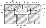
図7に示されるように、マルチチップモジュール210の一次成型部270は、一対の対向縁部271a,271bを有している。一対の対向縁部271a,271bは、一次成型部270の長手方向の両縁部である。各対向縁部271a,271bは、外縁に向かうほど、板厚の減少するテーパ形状に形成されている。各対向縁部271a,271bは、第一実施形態の対向縁部71(図1(d)参照)と実質的に同一の形状であって、一次成型部270の板厚方向における中心面CPに対して面対称であり、且つ角部273a,273bに面取りが施されている。
As shown in FIG. 7, the
図5及び図6に示されるように、マルチチップモジュール210のリード部材250は、第一実施形態の延出部50a(図1(a)参照)に相当する延出部250aを有している。各延出部250aは、第一実施形態の第一延伸部分51及び第二延伸部分52(図1(b)参照)と実施的に同一である、第一延伸部分251及び第二延伸部分252を形成している。第一延伸部分251は、一次成型部270の側面から、一次成型部270の板面方向に沿って延伸している部位である。第二延伸部分252は、リード部材250の屈曲により、第一延伸部分251と連続しつつ、一次成型部270の板厚方向に沿って延伸している部位である。延出部250aの延出方向に沿う一対の対向側部252a,252bであって、第一延伸部分251から第二延伸部分252に亘って延伸している対向側部252a,252bは、外縁に向かうほど、板厚の減少するテーパ形状に形成されている。第一延伸部分251及び第二延伸部分252の板面方向に沿い且つ第一延伸部分251及び第二延伸部分252の板厚方向の中心を通る仮想面を中心面CP1とすると、各対向側部252a,252bは、中心面CP1に対して面対称な形状である。
As shown in FIGS. 5 and 6, the
図7に示されるように、第二実施形態によるGCU200を製造する工程において用いられる金型220は、割型21及び割型22と、第一実施形態の割型23(図2参照)に相当する割型223と、を備えている。割型223は、キャビティ27に溶融した成形材料を充填するためのゲート226を有している。ゲート226は、割型21に形成されたゲート25と対向している。
As shown in FIG. 7, the
以上の金型220を用いて、GCU200を製造する工程について、以下図5〜図7に基づいて詳細に説明する。尚、第一実施形態の製造方法と実質的に同一である型締め工程及び離型工程は、説明を省略する。
The process of manufacturing the
(設置工程)
設置工程では、一次成型部270の一方の対向縁部271aがキャビティ27に開口するゲート25の開口部25aに対向するように、マルチチップモジュール210は、キャビティ27内に設置される。このマルチチップモジュール210の設置により、一次成型部270の他方の対向縁部271bは、キャビティ27に開口するゲート226の開口部226aに対向する。以上により、一対の開口部25a,226aと個々に対向する一対の対向縁部271a,271bは、対応する開口部25a,226aに近接するほど板厚が減少する。
(Installation process)
In the installation process, the
また、開口部25aからキャビティ27に充填される成形材料は、ゲート25の延伸方向に沿って開口部25aから離間する離間方向に流動する。故に、開口部25aから離間する離間方向を、成形材料の流動方向FD1とする。一方、開口部226aからキャビティ27に充填される成形材料は、ゲート226の延伸方向に沿って開口部226aから離間する離間方向に流動する。故に、開口部226aから離間する離間方向を、成形材料の流動方向FD2とする。マルチチップモジュール210は、一次成型部270の板面方向及び延出部250aの幅方向がこれら流動方向FD1,FD2に沿うように、キャビティ27内に設置される。これにより、一対の対向側部252a,252bは、対応する各開口部25a,226aに近接するほど板厚が減少する。
In addition, the molding material filled in the
(充填工程)
充填工程では、型締め工程によって型締めされた金型220のキャビティ27に、溶融された成形材料が、ゲート25及びゲート226を通じて、予め設定された圧力にて充填される。ゲート25を通じてキャビティ27に充填された成形材料は、開口部25aと対向している対向縁部271aに接触し、対向縁部271aに沿って流動する。また、ゲート226を通じてキャビティ27に充填された成形材料は、開口部226aと対向している対向縁部271bに接触し、対向縁部271bに沿って流動する。そして、成形材料は、一次成型部270等の周囲を囲む二次成型部80を形成する。以上の充填工程の後、離型工程を経て、GCU200は製造される。
(Filling process)
In the filling process, the melted molding material is filled into the
ここまで説明した第二実施形態では、ゲート25を通じてキャビティ27に充填される成形材料は、対向縁部271aによって流動を止められることなく、対向縁部271aに沿って円滑に流動し得る。加えて、ゲート226を通じてキャビティ27に充填される成形材料は、対向縁部271bによって流動を止められることなく、対向縁部271bに沿って円滑に流動し得る。以上により、金型220に互いに対向する一対のゲート25,226が形成されていても、成形材料から一次成型部270に作用する抵抗力は、低減される。したがって、一次成型部270を含むマルチチップモジュール210を金型220に固定することなく、一次成型部270の周囲を成形材料によって覆ったGCU200を提供することができる。
In the second embodiment described so far, the molding material filled into the
加えて第二実施形態では、ゲート25からキャビティ27内に充填される成形材料の流動方向FD1と、ゲート226からキャビティ27内に充填される成形材料の流動方向FD2とは、互いに対向する。故に、ゲート25から充填される成形材料が対向縁部271aに作用させる抵抗力と、ゲート226から充填される成形材料が対向縁部271bに作用させる抵抗力とは、互いに相殺し合う。
In addition, in the second embodiment, the flow direction FD1 of the molding material filled into the
また第二実施形態では、リード部材250の対向側部252a,252bは、各ゲート25,226の各開口部25a,226aに近接するほど板厚の減少する形状である。故に、成形材料は、対向側部252a,252bによって流動を止められることなく、対向側部252a,252bに沿って円滑に流動し得る。以上により、リード部材250を通じて成形材料から一次成型部270に作用する抵抗力は、低減される。
In the second embodiment, the opposing
これらによって、一次成型部270に作用する抵抗力の総和は、確実に低減される。したがって、一次成型部270を含むマルチチップモジュール210の金型220への固定がさらに確実でなくても、一次成型部270の周囲は、成形材料によって確実に覆われる。
By these, the sum total of the resistance force which acts on the primary shaping | molding
尚、第二実施形態において、一次成型部270が特許請求の範囲の「インサート部」に相当し、GCU200が特許請求の範囲の「グロープラグ制御装置」に相当する。
In the second embodiment, the
(第三実施形態)
図8〜図10に示される本発明の第三実施形態は、第二実施形態の変形例である。第三実施形態によるGCU300は、第二実施形態のマルチチップモジュール210(図5参照)に相当する、マルチチップモジュール310を備えている。以下、第三実施形態によるGCU300について、詳細に説明する。
(Third embodiment)
The third embodiment of the present invention shown in FIGS. 8 to 10 is a modification of the second embodiment. The
マルチチップモジュール310の一次成型部370は、一対の対向縁部371a,371bを有している。一対の対向縁部371a,371bは、一次成型部370の長手方向の両縁部である。各対向縁部371a,371bは、外縁に向かうほど、板厚の減少するテーパ形状に形成されている。各対向縁部371a,371bの各先端部分372a,372bは、一次成型部370の中心面CPよりもターミナル部材60側にずれて位置している。また、各対向縁部371a,371bの角部373a,373bには、面取りが施されている。
The
マルチチップモジュール310のリード部材350は、第二実施形態の延出部250a(図5参照)に相当する延出部350aを有している。延出部350aの延出方向と直交する断面の形状は、台形形状である。延出部350aの第一延伸部分351の幅は、ターミナル部材60から離間するに従って狭くなっている。延出部350aの第二延伸部分352の幅は、一次成型部370から離間するほど狭くなっている。以上により、延出部350aの一対の対向側部352a,352bは、外縁に向かうほど、板厚が減少している。
The
ここまで説明した第三実施形態のように、各対向縁部371a,371bの各先端部分372a,372bが中心面CPに対してずれて位置していても、成形材料は、各対向縁部371a,371bに沿って円滑に流動し得る。故に、成形材料は、対向縁部371a,371bによって流動を止められることはない。以上により、成形材料から一次成型部370に作用する抵抗力は、低減される。したがって、一次成型部370を含むマルチチップモジュール310を金型220に固定することなく、一次成型部370の周囲を成形材料によって覆ったGCU300を提供することができる。
As in the third embodiment described so far, even if the
加えて第三実施形態では、各先端部分372a,372bが、中心面CPよりもターミナル部材60側にずれて位置している。故に、各対向縁部371a,371bに沿って流動する成形材料は、板厚方向においてターミナル部材60側に向かう抵抗力RFを一次成型部370に作用させる。これにより、一次成型部370から延出する延出部350aは、ターミナル部材60に向けて押し付けられる。
In addition, in 3rd embodiment, each front-end |
また、延出部350aの第一延伸部分351に沿って流動する成形材料は、ターミナル部材60側に向かう抵抗力RF11をリード部材350に作用させる。この抵抗力RF11によって、延出部350aは、ターミナル部材60に向けて押し付けられる。また、延出部350aの第二延伸部分352に成形材料から作用する抵抗力RF12は、一次成型部370の長手方向に二列で並ぶ延出部350aの配置によって、互いに相殺し合う。故に、延出部350aのターミナル部材60への保持は、第二延伸部分352に作用する抵抗力RF12によっては妨げられない。
Further, the molding material that flows along the first extending
これらの抵抗力RF及び抵抗力RF11によって押し付けられた延出部350aは、ターミナル部材60に確実に保持され得る。したがって、ターミナル部材60を割型22に固定することによれば、マルチチップモジュール310の金型220への固定が確実でなくても、一次成型部370の周囲は、成形材料によって確実に覆われる。
The
尚、第三実施形態において、一次成型部370が特許請求の範囲の「インサート部」に相当し、GCU300が特許請求の範囲の「グロープラグ制御装置」に相当する。
In the third embodiment, the
(第四実施形態)
図11及び図12に示される本発明の第四実施形態は、第一実施形態の別の変形例である。第四実施形態によるGCU400では、一部のターミナル部材460の形状が第一実施形態のターミナル部材60(図1(b)参照)と異なっている。以下、第四実施形態によるGCU400について、詳細に説明する。
(Fourth embodiment)
The fourth embodiment of the present invention shown in FIGS. 11 and 12 is another modification of the first embodiment. In GCU400 by 4th embodiment, the shape of some
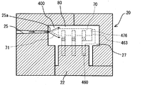
図11に示されるように、一対のターミナル部材460は、一次成型部70の長手方向に沿って並ぶ複数のターミナル部材の一部である。一対のターミナル部材460は、複数のターミナル部材のうちで、対向縁部71から最も離間して位置している。各ターミナル部材460は、保持部61及び電気接続部65に加えて、規制部463を有している。
As shown in FIG. 11, the pair of
規制部463は、ターミナル部材460において、保持部61及び電気接続部65間から分岐している。規制部463は、一次成型部70の長手方向に沿って対向縁部71から離間する方向に一旦延伸している。規制部463は、中間部分で一次成型部70の板厚方向に沿って曲がっている。一次成型部70の長手方向において対向縁部71と反対側に位置する当接縁部476に向かって、規制部463の先端部分は延伸している。規制部463は、先端部分を当接縁部476に当接させることにより、対向縁部71から当接縁部476に向かう方向への一次成型部70の移動を規制する。
The restricting
ここまで説明した第四実施形態の充填工程において、ゲート25を通じてキャビティ27に充填された成形材料は、開口部25aと対向している対向縁部71に接触し、対向縁部71に沿って流動する。このとき、成形材料からの抵抗力の作用によって、開口部25aから離間する離間方向であって、対向縁部71から当接縁部476に向かう方向に、一次成型部70は移動しようとする。しかし、一次成型部70は、割型22に固定されたターミナル部材460の有する規制部463によって、離間方向への移動を規制される。故に、金型20への一次成型部70の固定が確実になされなくても、一次成型部70の周囲は、成形材料によって確実に覆われる。
In the filling process of the fourth embodiment described so far, the molding material filled in the
尚、第四実施形態において、ターミナル部材460が特許請求の範囲の「保持部材」に相当し、GCU400が特許請求の範囲の「グロープラグ制御装置」に相当する。
In the fourth embodiment, the
(他の実施形態)
以上、本発明による複数の実施形態について説明したが、本発明は、上記実施形態に限定して解釈されるものではなく、本発明の要旨を逸脱しない範囲内において種々の実施形態及び組み合わせに適用することができる。
(Other embodiments)
Although a plurality of embodiments according to the present invention have been described above, the present invention is not construed as being limited to the above embodiments, and can be applied to various embodiments and combinations without departing from the gist of the present invention. can do.
上記実施形態において、対向縁部の有する一対の傾斜面は、共に長手方向に対する板厚方向の変化率が一定であった。しかし、傾斜面の傾斜の変化率は、一定でなくてもよい。例えば、長手方向に対する板厚方向の変化率は、対向縁部の外縁に向かうに従って大きくなっていてもよい。又は、長手方向に対する板厚方向の変化率は、対向縁部の外縁に向かうに従って小さくなっていてもよい。 In the above embodiment, the rate of change in the plate thickness direction with respect to the longitudinal direction is constant for the pair of inclined surfaces of the opposing edge portions. However, the change rate of the inclination of the inclined surface may not be constant. For example, the rate of change in the plate thickness direction with respect to the longitudinal direction may be increased toward the outer edge of the opposing edge. Alternatively, the rate of change in the plate thickness direction with respect to the longitudinal direction may become smaller toward the outer edge of the opposing edge.
上記第一実施形態等において、対向縁部の先端部分は、一次成型部の仮想の中心面上に位置していた。また、上記第三実施形態において、対向縁部の先端部分は、仮想の中心面に対して、ターミナル部材側にずれて位置していた。しかし、対向縁部の位置は、仮想の中心面に対して、ターミナル部材とは反対側にずれて位置していてもよい。 In the first embodiment and the like, the tip portion of the opposing edge portion is located on the virtual center plane of the primary molding portion. Moreover, in the said 3rd embodiment, the front-end | tip part of the opposing edge part has shifted | deviated and located in the terminal member side with respect to the virtual center plane. However, the position of the opposing edge may be shifted to the opposite side of the terminal member with respect to the virtual center plane.
上記実施形態において、一次成型部の板面方向は、キャビティ内を流動する成形材料の流動方向に沿っていた。また、リード部材の延出部の幅方向は、キャビティ内を流動する成形材料の流動方向に沿っていた。しかし、これら板面方向及び幅方向は、成形材料の流動方向に沿っていなくてもよい。 In the said embodiment, the plate | board surface direction of the primary molding part was along the flow direction of the molding material which flows through the inside of a cavity. Further, the width direction of the extending portion of the lead member was along the flow direction of the molding material flowing in the cavity. However, the plate surface direction and the width direction may not be along the flow direction of the molding material.
上記実施形態において、一次成型部は、熱硬化性樹脂によって形成されていた。また、二次成型部は、熱可塑性樹脂によって形成されていた。しかし、例えば一次成型部が、熱可塑性樹脂によって形成されていてもよい。又は、二次成型部が、熱硬化性樹脂によって形成されていてもよい。さらに、熱硬化性樹脂及び熱可塑性樹脂として上記実施形態で例示したもの以外の樹脂材料が、一次成型部及び二次成型部の成形材料として、適宜用いられてもよい。 In the said embodiment, the primary molding part was formed with the thermosetting resin. Moreover, the secondary molding part was formed with the thermoplastic resin. However, for example, the primary molded part may be formed of a thermoplastic resin. Or the secondary molding part may be formed with the thermosetting resin. Furthermore, resin materials other than those exemplified in the above embodiment as the thermosetting resin and the thermoplastic resin may be appropriately used as the molding material for the primary molding part and the secondary molding part.
RF,RF11,RF12 抵抗力
FD,FD1,FD2 流動方向
CP 一次成型部の仮想中心面
CP1 延出部の仮想中心面
10,210,310 マルチチップモジュール
20,220 金型
21,22,23,223 割型
25,226 ゲート
25a,226a 開口部
27 キャビティ
40 制御部
41 制御IC
42 パワーIC
50,250,350 リード部材
50a,250a,350a 延出部
51,251,351 第一延伸部
52,252,352 第二延伸部
252a,252b,352a,352b 対向側部
60,460 ターミナル部材(保持部材)
61 保持部
463 規制部
65 電気接続部
70,270,370 一次成型部(インサート部)
71,271a,271b,371a,371b 対向縁部
72,372a,372b 先端部分
73,273a,273b,373a,373b 角部
74 傾斜面
75 本体部
476 当接縁部
80 二次成型部
81 コネクタ部
81a 嵌合空間
82 係止爪
100,200,300,400 GCU(グロープラグ制御装置)
RF, RF11, RF12 Resistance force FD, FD1, FD2 Flow direction CP Virtual center plane CP1 of primary molding part Virtual center planes 10, 210, 310 of extended
42 Power IC
50, 250, 350
61
71, 271a, 271b, 371a, 371b Opposing
Claims (10)
前記インサート部において前記キャビティに開口する前記ゲートの開口部と対向する対向縁部は、前記開口部に近接するほど板厚の減少する形状であることを特徴とするグロープラグ制御装置。 A plate-like insert portion whose periphery is covered with a molding material filled into a cavity in a mold through a gate, and a control for controlling heat generation of the glow plug by being accommodated in the insert portion and connected to the glow plug. A glow plug control device comprising:
The glow plug control device according to claim 1, wherein an opposing edge portion of the insert portion that faces the opening portion of the gate that opens into the cavity has a shape in which a plate thickness decreases as the opening portion approaches the opening portion.
前記キャビティ内において前記リード部材を保持する保持部材と、をさらに備え、
前記対向縁部の先端部分は、前記インサート部の板面方向に沿い且つ当該インサート部の板厚方向の中心を通る仮想中心面よりも、前記保持部材側にずれて位置することを特徴とする請求項1に記載のグロープラグ制御装置。 A lead member connected to the control portion inside the insert portion and extending to the outside of the insert portion;
A holding member for holding the lead member in the cavity,
The tip portion of the opposing edge is positioned so as to be shifted to the holding member side from a virtual center plane that passes along the plate surface direction of the insert portion and passes through the center of the insert portion in the plate thickness direction. The glow plug control device according to claim 1.
前記リード部材の幅方向は、前記開口部から離間する離間方向に沿うことを特徴とする請求項1〜4のいずれか一項に記載のグロープラグ制御装置。 A strip-shaped lead member connected to the control unit inside the insert part and extending to the outside of the insert part;
The glow plug control device according to any one of claims 1 to 4, wherein a width direction of the lead member is along a separation direction that is separated from the opening.
前記キャビティに開口する前記一対のゲートの各開口部と個々に対向する一対の前記対向縁部は、対応する前記開口部に近接するほど板厚の減少する形状であることを特徴とする請求項1〜7のいずれか一項に記載のグロープラグ制御装置。 A glow plug control device comprising the insert part surrounded by the molding material filled through a pair of the gates formed to face the mold,
The pair of facing edge portions individually facing each opening portion of the pair of gates opening in the cavity have a shape in which a plate thickness decreases as the opening portion approaches the corresponding opening portion. The glow plug control device according to any one of 1 to 7.
前記インサート部において板厚の減少する形状である対向縁部が、前記キャビティに開口する前記ゲートの開口部に対向するように、前記インサート部を前記キャビティ内に設置する設置工程と、
前記設置工程において、前記インサート部の設置された前記キャビティ内に、前記ゲートを通じて溶融された前記成形材料を充填する充填工程と、
を含むことを特徴とするグロープラグ制御装置の製造方法。 A plate-like insert portion whose periphery is covered with a molding material filled into a cavity in a mold through a gate, and a control for controlling heat generation of the glow plug by being accommodated in the insert portion and connected to the glow plug. And a method of manufacturing a glow plug control device comprising:
An installation step of installing the insert portion in the cavity such that an opposing edge having a shape in which the plate thickness decreases in the insert portion is opposed to an opening portion of the gate opening in the cavity;
In the installation step, a filling step of filling the molding material melted through the gate into the cavity in which the insert portion is installed;
A method for manufacturing a glow plug control device comprising:
Priority Applications (1)
| Application Number | Priority Date | Filing Date | Title |
|---|---|---|---|
| JP2011037405A JP5672057B2 (en) | 2011-02-23 | 2011-02-23 | Manufacturing method of glow plug control device |
Applications Claiming Priority (1)
| Application Number | Priority Date | Filing Date | Title |
|---|---|---|---|
| JP2011037405A JP5672057B2 (en) | 2011-02-23 | 2011-02-23 | Manufacturing method of glow plug control device |
Publications (2)
| Publication Number | Publication Date |
|---|---|
| JP2012172632A true JP2012172632A (en) | 2012-09-10 |
| JP5672057B2 JP5672057B2 (en) | 2015-02-18 |
Family
ID=46975752
Family Applications (1)
| Application Number | Title | Priority Date | Filing Date |
|---|---|---|---|
| JP2011037405A Active JP5672057B2 (en) | 2011-02-23 | 2011-02-23 | Manufacturing method of glow plug control device |
Country Status (1)
| Country | Link |
|---|---|
| JP (1) | JP5672057B2 (en) |
Cited By (1)
| Publication number | Priority date | Publication date | Assignee | Title |
|---|---|---|---|---|
| JP2016013670A (en) * | 2014-07-03 | 2016-01-28 | 株式会社デンソー | Resin-molded article |
Citations (9)
| Publication number | Priority date | Publication date | Assignee | Title |
|---|---|---|---|---|
| JPS6047429A (en) * | 1983-08-25 | 1985-03-14 | Fujitsu Ltd | Mold for resin package |
| JPS63102246U (en) * | 1986-12-22 | 1988-07-02 | ||
| JPH03277859A (en) * | 1990-03-27 | 1991-12-09 | Nok Corp | Resin pulley and manufacture thereof |
| JPH06111653A (en) * | 1991-09-28 | 1994-04-22 | Omron Corp | Method for forming insertion part of terminal fitting of electric equipment |
| JPH10296738A (en) * | 1997-04-29 | 1998-11-10 | Ngk Spark Plug Co Ltd | Insert molded body and manufacture thereof |
| JP2002355866A (en) * | 2001-05-31 | 2002-12-10 | Daiwa Kasei Ind Co Ltd | Injection molding method |
| JP2007296682A (en) * | 2006-04-28 | 2007-11-15 | Nok Corp | Inserted member |
| JP2009000854A (en) * | 2007-06-20 | 2009-01-08 | Incs Inc | Injection molding device |
| JP2010164005A (en) * | 2009-01-16 | 2010-07-29 | Denso Corp | Glow plug energization control device |
-
2011
- 2011-02-23 JP JP2011037405A patent/JP5672057B2/en active Active
Patent Citations (9)
| Publication number | Priority date | Publication date | Assignee | Title |
|---|---|---|---|---|
| JPS6047429A (en) * | 1983-08-25 | 1985-03-14 | Fujitsu Ltd | Mold for resin package |
| JPS63102246U (en) * | 1986-12-22 | 1988-07-02 | ||
| JPH03277859A (en) * | 1990-03-27 | 1991-12-09 | Nok Corp | Resin pulley and manufacture thereof |
| JPH06111653A (en) * | 1991-09-28 | 1994-04-22 | Omron Corp | Method for forming insertion part of terminal fitting of electric equipment |
| JPH10296738A (en) * | 1997-04-29 | 1998-11-10 | Ngk Spark Plug Co Ltd | Insert molded body and manufacture thereof |
| JP2002355866A (en) * | 2001-05-31 | 2002-12-10 | Daiwa Kasei Ind Co Ltd | Injection molding method |
| JP2007296682A (en) * | 2006-04-28 | 2007-11-15 | Nok Corp | Inserted member |
| JP2009000854A (en) * | 2007-06-20 | 2009-01-08 | Incs Inc | Injection molding device |
| JP2010164005A (en) * | 2009-01-16 | 2010-07-29 | Denso Corp | Glow plug energization control device |
Cited By (1)
| Publication number | Priority date | Publication date | Assignee | Title |
|---|---|---|---|---|
| JP2016013670A (en) * | 2014-07-03 | 2016-01-28 | 株式会社デンソー | Resin-molded article |
Also Published As
| Publication number | Publication date |
|---|---|
| JP5672057B2 (en) | 2015-02-18 |
Similar Documents
| Publication | Publication Date | Title |
|---|---|---|
| KR100780830B1 (en) | Semiconductor device | |
| US8258622B2 (en) | Power device package and semiconductor package mold for fabricating the same | |
| US9698091B2 (en) | Power semiconductor device | |
| CN105684144B (en) | Semiconductor device, semiconductor module | |
| EP2963684B1 (en) | Power semiconductor device | |
| KR101168436B1 (en) | Smt connector | |
| US20180306619A1 (en) | Flow meter | |
| JP5038273B2 (en) | Resin molded semiconductor sensor and manufacturing method | |
| US20160111379A1 (en) | Semiconductor device | |
| US10163752B2 (en) | Semiconductor device | |
| JP5648527B2 (en) | Semiconductor device with connector and manufacturing method thereof | |
| EP2814055B1 (en) | Semiconductor device and semiconductor device fabrication method | |
| JP5672057B2 (en) | Manufacturing method of glow plug control device | |
| US8242587B2 (en) | Electronic device and pressure sensor | |
| JP2008211124A (en) | Semiconductor device storing package | |
| JP5720514B2 (en) | Manufacturing method of semiconductor device | |
| US7447041B2 (en) | Compression connection for vertical IC packages | |
| US10644423B2 (en) | Semiconductor module | |
| US20180102300A1 (en) | Connectable Package Extender for Semiconductor Device Package | |
| JP6063777B2 (en) | Sensor device | |
| US11452228B2 (en) | Driver | |
| CN113728427B (en) | Semiconductor device with a semiconductor device having a plurality of semiconductor chips | |
| JP5762856B2 (en) | Current sensor | |
| CN111406311A (en) | Electronic module and method for manufacturing electronic module | |
| CN104185395A (en) | Controller unit |
Legal Events
| Date | Code | Title | Description |
|---|---|---|---|
| A621 | Written request for application examination |
Free format text: JAPANESE INTERMEDIATE CODE: A621 Effective date: 20130911 |
|
| A977 | Report on retrieval |
Free format text: JAPANESE INTERMEDIATE CODE: A971007 Effective date: 20140526 |
|
| A131 | Notification of reasons for refusal |
Free format text: JAPANESE INTERMEDIATE CODE: A131 Effective date: 20140603 |
|
| A521 | Request for written amendment filed |
Free format text: JAPANESE INTERMEDIATE CODE: A523 Effective date: 20140804 |
|
| TRDD | Decision of grant or rejection written | ||
| A01 | Written decision to grant a patent or to grant a registration (utility model) |
Free format text: JAPANESE INTERMEDIATE CODE: A01 Effective date: 20141125 |
|
| A61 | First payment of annual fees (during grant procedure) |
Free format text: JAPANESE INTERMEDIATE CODE: A61 Effective date: 20141208 |
|
| R151 | Written notification of patent or utility model registration |
Ref document number: 5672057 Country of ref document: JP Free format text: JAPANESE INTERMEDIATE CODE: R151 |
|
| R250 | Receipt of annual fees |
Free format text: JAPANESE INTERMEDIATE CODE: R250 |
|
| R250 | Receipt of annual fees |
Free format text: JAPANESE INTERMEDIATE CODE: R250 |
|
| R250 | Receipt of annual fees |
Free format text: JAPANESE INTERMEDIATE CODE: R250 |
|
| R250 | Receipt of annual fees |
Free format text: JAPANESE INTERMEDIATE CODE: R250 |
|
| R250 | Receipt of annual fees |
Free format text: JAPANESE INTERMEDIATE CODE: R250 |
|
| R250 | Receipt of annual fees |
Free format text: JAPANESE INTERMEDIATE CODE: R250 |
|
| R250 | Receipt of annual fees |
Free format text: JAPANESE INTERMEDIATE CODE: R250 |