JP2012172500A - Facility with charging station - Google Patents
Facility with charging station Download PDFInfo
- Publication number
- JP2012172500A JP2012172500A JP2011038849A JP2011038849A JP2012172500A JP 2012172500 A JP2012172500 A JP 2012172500A JP 2011038849 A JP2011038849 A JP 2011038849A JP 2011038849 A JP2011038849 A JP 2011038849A JP 2012172500 A JP2012172500 A JP 2012172500A
- Authority
- JP
- Japan
- Prior art keywords
- charging
- charging stand
- charging station
- electric vehicle
- parking space
- Prior art date
- Legal status (The legal status is an assumption and is not a legal conclusion. Google has not performed a legal analysis and makes no representation as to the accuracy of the status listed.)
- Pending
Links
Images


Classifications
-
- B—PERFORMING OPERATIONS; TRANSPORTING
- B60—VEHICLES IN GENERAL
- B60L—PROPULSION OF ELECTRICALLY-PROPELLED VEHICLES; SUPPLYING ELECTRIC POWER FOR AUXILIARY EQUIPMENT OF ELECTRICALLY-PROPELLED VEHICLES; ELECTRODYNAMIC BRAKE SYSTEMS FOR VEHICLES IN GENERAL; MAGNETIC SUSPENSION OR LEVITATION FOR VEHICLES; MONITORING OPERATING VARIABLES OF ELECTRICALLY-PROPELLED VEHICLES; ELECTRIC SAFETY DEVICES FOR ELECTRICALLY-PROPELLED VEHICLES
- B60L3/00—Electric devices on electrically-propelled vehicles for safety purposes; Monitoring operating variables, e.g. speed, deceleration or energy consumption
- B60L3/0023—Detecting, eliminating, remedying or compensating for drive train abnormalities, e.g. failures within the drive train
- B60L3/0069—Detecting, eliminating, remedying or compensating for drive train abnormalities, e.g. failures within the drive train relating to the isolation, e.g. ground fault or leak current
-
- B—PERFORMING OPERATIONS; TRANSPORTING
- B60—VEHICLES IN GENERAL
- B60L—PROPULSION OF ELECTRICALLY-PROPELLED VEHICLES; SUPPLYING ELECTRIC POWER FOR AUXILIARY EQUIPMENT OF ELECTRICALLY-PROPELLED VEHICLES; ELECTRODYNAMIC BRAKE SYSTEMS FOR VEHICLES IN GENERAL; MAGNETIC SUSPENSION OR LEVITATION FOR VEHICLES; MONITORING OPERATING VARIABLES OF ELECTRICALLY-PROPELLED VEHICLES; ELECTRIC SAFETY DEVICES FOR ELECTRICALLY-PROPELLED VEHICLES
- B60L53/00—Methods of charging batteries, specially adapted for electric vehicles; Charging stations or on-board charging equipment therefor; Exchange of energy storage elements in electric vehicles
- B60L53/10—Methods of charging batteries, specially adapted for electric vehicles; Charging stations or on-board charging equipment therefor; Exchange of energy storage elements in electric vehicles characterised by the energy transfer between the charging station and the vehicle
- B60L53/11—DC charging controlled by the charging station, e.g. mode 4
-
- B—PERFORMING OPERATIONS; TRANSPORTING
- B60—VEHICLES IN GENERAL
- B60L—PROPULSION OF ELECTRICALLY-PROPELLED VEHICLES; SUPPLYING ELECTRIC POWER FOR AUXILIARY EQUIPMENT OF ELECTRICALLY-PROPELLED VEHICLES; ELECTRODYNAMIC BRAKE SYSTEMS FOR VEHICLES IN GENERAL; MAGNETIC SUSPENSION OR LEVITATION FOR VEHICLES; MONITORING OPERATING VARIABLES OF ELECTRICALLY-PROPELLED VEHICLES; ELECTRIC SAFETY DEVICES FOR ELECTRICALLY-PROPELLED VEHICLES
- B60L53/00—Methods of charging batteries, specially adapted for electric vehicles; Charging stations or on-board charging equipment therefor; Exchange of energy storage elements in electric vehicles
- B60L53/30—Constructional details of charging stations
- B60L53/305—Communication interfaces
-
- Y—GENERAL TAGGING OF NEW TECHNOLOGICAL DEVELOPMENTS; GENERAL TAGGING OF CROSS-SECTIONAL TECHNOLOGIES SPANNING OVER SEVERAL SECTIONS OF THE IPC; TECHNICAL SUBJECTS COVERED BY FORMER USPC CROSS-REFERENCE ART COLLECTIONS [XRACs] AND DIGESTS
- Y02—TECHNOLOGIES OR APPLICATIONS FOR MITIGATION OR ADAPTATION AGAINST CLIMATE CHANGE
- Y02T—CLIMATE CHANGE MITIGATION TECHNOLOGIES RELATED TO TRANSPORTATION
- Y02T10/00—Road transport of goods or passengers
- Y02T10/60—Other road transportation technologies with climate change mitigation effect
- Y02T10/70—Energy storage systems for electromobility, e.g. batteries
-
- Y—GENERAL TAGGING OF NEW TECHNOLOGICAL DEVELOPMENTS; GENERAL TAGGING OF CROSS-SECTIONAL TECHNOLOGIES SPANNING OVER SEVERAL SECTIONS OF THE IPC; TECHNICAL SUBJECTS COVERED BY FORMER USPC CROSS-REFERENCE ART COLLECTIONS [XRACs] AND DIGESTS
- Y02—TECHNOLOGIES OR APPLICATIONS FOR MITIGATION OR ADAPTATION AGAINST CLIMATE CHANGE
- Y02T—CLIMATE CHANGE MITIGATION TECHNOLOGIES RELATED TO TRANSPORTATION
- Y02T10/00—Road transport of goods or passengers
- Y02T10/60—Other road transportation technologies with climate change mitigation effect
- Y02T10/7072—Electromobility specific charging systems or methods for batteries, ultracapacitors, supercapacitors or double-layer capacitors
-
- Y—GENERAL TAGGING OF NEW TECHNOLOGICAL DEVELOPMENTS; GENERAL TAGGING OF CROSS-SECTIONAL TECHNOLOGIES SPANNING OVER SEVERAL SECTIONS OF THE IPC; TECHNICAL SUBJECTS COVERED BY FORMER USPC CROSS-REFERENCE ART COLLECTIONS [XRACs] AND DIGESTS
- Y02—TECHNOLOGIES OR APPLICATIONS FOR MITIGATION OR ADAPTATION AGAINST CLIMATE CHANGE
- Y02T—CLIMATE CHANGE MITIGATION TECHNOLOGIES RELATED TO TRANSPORTATION
- Y02T90/00—Enabling technologies or technologies with a potential or indirect contribution to GHG emissions mitigation
- Y02T90/10—Technologies relating to charging of electric vehicles
- Y02T90/12—Electric charging stations
-
- Y—GENERAL TAGGING OF NEW TECHNOLOGICAL DEVELOPMENTS; GENERAL TAGGING OF CROSS-SECTIONAL TECHNOLOGIES SPANNING OVER SEVERAL SECTIONS OF THE IPC; TECHNICAL SUBJECTS COVERED BY FORMER USPC CROSS-REFERENCE ART COLLECTIONS [XRACs] AND DIGESTS
- Y02—TECHNOLOGIES OR APPLICATIONS FOR MITIGATION OR ADAPTATION AGAINST CLIMATE CHANGE
- Y02T—CLIMATE CHANGE MITIGATION TECHNOLOGIES RELATED TO TRANSPORTATION
- Y02T90/00—Enabling technologies or technologies with a potential or indirect contribution to GHG emissions mitigation
- Y02T90/10—Technologies relating to charging of electric vehicles
- Y02T90/14—Plug-in electric vehicles
-
- Y—GENERAL TAGGING OF NEW TECHNOLOGICAL DEVELOPMENTS; GENERAL TAGGING OF CROSS-SECTIONAL TECHNOLOGIES SPANNING OVER SEVERAL SECTIONS OF THE IPC; TECHNICAL SUBJECTS COVERED BY FORMER USPC CROSS-REFERENCE ART COLLECTIONS [XRACs] AND DIGESTS
- Y02—TECHNOLOGIES OR APPLICATIONS FOR MITIGATION OR ADAPTATION AGAINST CLIMATE CHANGE
- Y02T—CLIMATE CHANGE MITIGATION TECHNOLOGIES RELATED TO TRANSPORTATION
- Y02T90/00—Enabling technologies or technologies with a potential or indirect contribution to GHG emissions mitigation
- Y02T90/10—Technologies relating to charging of electric vehicles
- Y02T90/16—Information or communication technologies improving the operation of electric vehicles
Landscapes
- Engineering & Computer Science (AREA)
- Power Engineering (AREA)
- Transportation (AREA)
- Mechanical Engineering (AREA)
- Life Sciences & Earth Sciences (AREA)
- Sustainable Development (AREA)
- Sustainable Energy (AREA)
- Charge And Discharge Circuits For Batteries Or The Like (AREA)
Abstract
Description
本発明は、電気自動車用の充電装置が設けられた充電スタンド設置施設に関するものである。 The present invention relates to a charging stand installation facility provided with a charging device for an electric vehicle.
近年、地球温暖化に対する懸念や、それに伴うCO2排出削減が求められており、自動車においても、CO2を排出する化石燃料を用いない電気自動車に対する関心が高まっており、一部実用化されている。それに伴い電気自動車に充電するための充電スタンド等の充電装置が設置され、更なる普及が求められている。
この充電スタンド設置施設は、ガソリンスタンドのようなガソリン等の化石燃料を貯蓄する比較的大型の貯蔵庫を必要とせず、商用電源等の電力を利用可能な場所であれば、公園、駐車場、駅前広場等に設置可能である。
In recent years, concerns about global warming and the accompanying reduction of CO2 emissions have been demanded, and in automobiles, interest in electric vehicles that do not use fossil fuels that emit CO2 has increased, and some have been put into practical use. Accordingly, a charging device such as a charging stand for charging an electric vehicle is installed, and further spread is required.
This charging station installation facility does not require a relatively large storage for storing fossil fuels such as gasoline like a gas station. It can be installed in a plaza.
例えば、特許文献1には、電力を自動車へ送る充電装置が、駐車場の上方スペース又は下方スペースに設置されている、自動車への充電システムに関する発明が記載されており、図3には、駐車場の駐車スペースの後方に設けられた通行可能箇所に充電スタンドが設けられている。
For example,
ところで、前記の充電システムにおいて、充電スタンドから電気自動車に充電するための電力量は比較的大きいため、例えば、運転操作を誤って車両が充電スタンドに衝突した場合、充電スタンドの破損のみならず、感電等の不具合が発生するおそれがあった。 By the way, in the above charging system, since the amount of power for charging the electric vehicle from the charging stand is relatively large, for example, when the vehicle collides with the charging stand accidentally, not only the charging stand is damaged, There was a risk of problems such as electric shock.
本発明は、前記の如き問題点を解消し、電気自動車に充電するための充電スタンドを安全に利用することができる充電スタンド設置施設を提供せんとするものである。 The present invention is intended to solve the above problems and provide a charging station installation facility that can safely use a charging station for charging an electric vehicle.
上記目的を達成するために、本発明は次のような構成としている。
すなわちこの発明に係る充電スタンド設置施設は、電気自動車用の充電スタンドが設置された充電スタンド設置所と、前記充電スタンド設置所を間にしてその両側にそれぞれに設けられた電気自動車が駐車可能な駐車スペースとを備え、前記充電スタンド設置所と前記駐車スペースとの間には、前記充電スタンド設置所と前記駐車スペースとを仕切る仕切部材が設けられていることを特徴とするものである。
In order to achieve the above object, the present invention is configured as follows.
That is, the charging station installation facility according to the present invention can park a charging station installation site where an electric vehicle charging station is installed, and electric vehicles installed on both sides of the charging station installation site. A parking space is provided, and a partition member is provided between the charging stand installation location and the parking space, and partitions the charging stand installation location from the parking space.
本発明に係る充電スタンド設置施設において、前記駐車スペースは、前記充電スタンドを利用する電気自動車が駐車するための標示が設けられているように構成してもよい。 In the charging station installation facility according to the present invention, the parking space may be configured such that an indication for parking an electric vehicle using the charging station is provided.
また本発明に係る充電スタンド設置施設において、前記充電スタンド設置所には、支柱が立設されていると共に、前記支柱間に前記充電スタンド設置所の上部を覆う屋根部が取付けられているように構成してもよい。 Further, in the charging stand installation facility according to the present invention, a support column is erected at the charging stand installation site, and a roof portion that covers an upper portion of the charging stand installation site is attached between the support columns. It may be configured.
また本発明に係る充電スタンド設置施設において、前記支柱には、それぞれ前記充電スタンドが設けられたことを示す標示が外側に向けて設けられているように構成してもよい。 Moreover, the charging stand installation facility which concerns on this invention WHEREIN: You may comprise so that the indicator which shows that the said charging stand was each provided in the said support | pillar was provided toward the outer side.
本発明によれば、電気自動車用の充電スタンドが設置された充電スタンド設置所と、前記充電スタンド設置所を間にしてその両側にそれぞれに設けられた電気自動車が駐車可能な駐車スペースとを備え、前記充電スタンド設置所と前記駐車スペースとの間には、前記充電スタンド設置所と前記駐車スペースとを仕切る仕切部材が設けられているので、充電するための電気自動車やその他の車両が充電スタンドに接近した場合に、仕切部材で阻止し、充電スタンドへの衝突や、それに伴う感電等の不具合の発生を抑えることができる。 According to the present invention, there are provided a charging stand installation place where a charging stand for an electric vehicle is installed, and a parking space for parking an electric vehicle provided on each side of the charging stand installation place. In addition, a partition member is provided between the charging stand installation location and the parking space so as to partition the charging stand installation location and the parking space, so that an electric vehicle or other vehicle for charging can be used as a charging stand. Can be prevented by the partition member, and the occurrence of problems such as a collision with the charging station and the associated electric shock can be suppressed.
本発明に係る充電スタンド設置施設において、駐車スペースが、前記充電スタンドを利用する電気自動車が駐車するための標示が設けられるように構成すれば、運転手が駐車スペースを容易に認識することができ、電気自動車を駐車スペースに誘導して、電気自動車が不用意に柱状体に衝突することを抑えることができる。 In the charging station installation facility according to the present invention, if the parking space is configured to be provided with an indication for parking the electric vehicle using the charging station, the driver can easily recognize the parking space. The electric vehicle can be guided to the parking space to prevent the electric vehicle from inadvertently colliding with the columnar body.
本発明に係る充電スタンド設置施設において、前記充電スタンド設置所には、支柱が立設されていると共に、前記支柱間に前記充電スタンド設置所の上部を覆う屋根部が取付けられているように構成すれば、充電スタンドに電気自動車等の車両が接近しても、充電スタンドに直接衝突することを抑えることが可能となり、加えて充電スタンドの周囲で降雨を避けて充電作業を安全にすることができる。 In the charging stand installation facility according to the present invention, the charging stand installation site is provided with a support column, and a roof portion that covers the upper part of the charging stand installation site is attached between the support column. Then, even if a vehicle such as an electric vehicle approaches the charging station, it is possible to suppress a direct collision with the charging station, and in addition, it is possible to make the charging work safe by avoiding rain around the charging station. it can.
本発明に係る充電スタンド設置施設において、支柱には、充電スタンドが設けられたことを示す標示が外側に向けて設けられるように構成すれば、充電スタンドの前後方向から接近する自動車や歩行者に充電スタンドの存在を知らせることができるので、ガソリン車等の一般の自動車がガソリンスタンドと誤って近づくことを防ぐことができる。 In the charging station installation facility according to the present invention, if the post is configured so that the sign indicating that the charging station is provided is provided outward, it is possible for a vehicle or a pedestrian approaching from the front-rear direction of the charging station. Since the presence of the charging station can be notified, it is possible to prevent a general automobile such as a gasoline vehicle from accidentally approaching the gasoline station.
次に、本発明を実施するための最良の形態について図面を参照し、具体的に説明する。
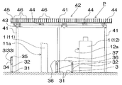
すなわち、図1〜6において、Pは充電スタンド設置所、1は前記充電スタンド設置所Pに設置された電気自動車用の充電スタンド、2は前記充電スタンド設置所Pを間にしてその両側に設けられた電気自動車Eが駐車可能な駐車スペース、3は前記充電スタンド設置所Pと駐車スペース2とを仕切る仕切部材であり、本発明に係る充電スタンド設置施設は、主に充電スタンド1が設置された充電スタンド設置所P、駐車スペース2及び仕切部材3とから構成されている。
Next, the best mode for carrying out the present invention will be specifically described with reference to the drawings.
That is, in FIGS. 1 to 6, P is a charging stand installation place, 1 is a charging stand for an electric vehicle installed at the charging stand installation place P, and 2 is provided on both sides of the charging stand installation place P. A parking space in which the electric vehicle E can be parked, 3 is a partition member that partitions the charging station installation place P and the
充電スタンド設置所Pに設置された充電スタンド1は、一般には商用電源を利用して比較的小容量の充電を目的とした継ぎ足し充電用の一般充電スタンド11と、蓄電池等の蓄電部材を利用して比較的短時間で大容量を充電する急速充電スタンド12とがある。本形態では、一般充電スタンド11と急速充電スタンド12とをそれぞれ1個ずつ用いているが、例えば、スーパー等の駐車場に用いる場合は、継ぎ足し充電の利用が多いので、一般充電スタンド11のみを用いてもよく、路線バス等の車庫、高速道路のサービスエリア、パーキングエリア、道の駅等、比較的短時間で大容量の充電を目的とすることが多い場合は、急速充電スタンド12のみを用いてもよい。
The
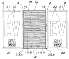
充電スタンド1が設置された充電スタンド設置所Pの左右両側には、充電するための電気自動車Eが駐車可能な駐車スペース2が設けられている。これによって、充電が必要な電気自動車Eが2台あっても、左右に分かれて駐車スペース2に駐車することができる。この場合、本形態のように充電スタンド1が2個あれば、それぞれの電気自動車Eに充電することができるので好ましい。更に、本形態のように、充電スタンド1において、一般充電スタンド11、急速充電スタンド12のそれぞれの操作面11a、12aが前側に面するようにすれば、利用者は、充電スタンド1に対して左右いずれに駐車しても、充電スタンド1を利用しやすくなる。なお前記操作面11a、12aは後側に面するようにしてもよい。
駐車スペース2には、本形態では、電気自動車Eが駐車する位置を囲んだ駐車枠21が設けられ、その駐車枠21の中には、充電スタンド1があることを示す文字や図形を含む標示22が設けられている。そして標示22は、その文字や図形が駐車スペース2の前方から読めるように配列されている。これにより、電気自動車Eの運転手は、充電するための駐車位置や向きを確認することができる。
In this embodiment, the
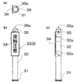
充電スタンド1が設置された充電スタンド設置所Pと駐車スペース2との間は、設置面に設けられた仕切部材3によって仕切られている。これにより、電気自動車Eが不必要に充電スタンド1に接近することを視覚的にも物理的にも防ぐことができる。図1において、前側に設けられた仕切部材3は、その一形態を示すものであり、設置面に固定された土台部31に可撓性を有する合成樹脂の柱状部32が取付けられて柱状体33を形成している。これにより、運転操作を誤って電気自動車Eが前記柱状部32に接触した場合、運転手には接触した衝撃を感知できるので、運転手が気付いて充電スタンド1にそれ以上接近しないようにできる。また前記接触により柱状部32が撓むため、電気自動車Eに凹みや破損等の不具合は生じにくく、また電気自動車Eが柱状部32から離れれば、柱状部32が元の形に復元することが期待できるので、柱状体33を衝突の都度取替える必要はない。なお柱状部32は、横断面略リング状の形態が用いられるが、可撓性を有していれば内部が詰まった形態でもよい。
The charging station installation place P where the
図7は、前記仕切部材3の柱状体33の説明図であり、(a)は平面図、(b)は正面図、(c)は側面図である。本形態では、柱状体33の柱状部32に充電スタンド設置所Pの前方から近づく電気自動車Eに接触注意を促すために、「接触注意」が標示されたサイン板34を取付けている。更に、夜間の視認性を高めるために、柱状部32の上端に発光部35を設け、柱状部32の周りに再帰反射機能を有する反射テープ32aを貼着させている。なお発光部35は、一般にはその頂部に太陽電池35aを備え、昼間時に充電した電力を発光部35の内部に設けられた蓄電池(図示せず)に蓄電し、夜間に発光するLED等の発光体(図示せず)を発光部35の側面に配置したものが用いられ、配線工事等のメンテナンスが不要となるので好ましいが、太陽電池の代わりに商用電力を用いて発光するものでもよい。
7A and 7B are explanatory views of the
また図1において、後側に設けられた仕切部材3は前述の柱状体33とは異なる形態であり、図8を用いて具体的に説明する。なお図8において、(a)は平面図、(b)は側面図、(c)は正面図を示している。図8に示された仕切部材3は、前後に間隔をおいて2個の土台部31が設けられ、前記土台部31に取付けられた柱状部32の上端に側面視逆L字状の連結部材36が取付けられ、更に柱状部32と同様な可撓性を有する合成樹脂製の梁材37がその両端で連結部材36に取付けられ、側面視門型の仕切部材3となされている。これにより、電気自動車Eがこの門型の仕切部材3に接触しても、2個の柱状体33が協働して充電スタンド1側に接近することを防ぐことができる。
Moreover, in FIG. 1, the
仕切部材3は、単に土台部31と柱状部32とからなる柱状体33を複数用いてもよく、前記サイン板34や発光部35を取付けた柱状体33や、前述のように、2個の柱状体33を用いて門型した形態を組み合わせて用いてもよい。また本形態のように仕切部材3を複数個用いる場合は、駐車スペース2の駐車枠21の長手方向に沿って仕切部材3を配置する方が好ましい。これにより、電気自動車Eを後退させながら駐車させる場合に、駐車枠21と仕切部材3とを目印にして電気自動車Eを誘導させることができるので、駐車枠21に対して長手方向に沿っているがどうか認識しやすく、電気自動車Eを駐車枠21内に止めやすい。
The
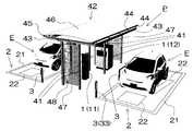
充電スタンド1が設置された充電スタンド設置所Pの前後には、間隔をおいて支柱41が立設している。これにより、充電スタンド1に対して電気自動車Eが前後どちらから接近しても充電スタンド1に衝突する前に支柱41と衝突するので、充電スタンド1への直接の衝突や、充電スタンド1の破損や感電等の不具合の発生を防ぐことができる。
Support posts 41 are erected at intervals before and after the charging station installation place P where the charging
支柱41は、一般には強度的に安定しておりコストの安い丸鋼管が用いられているが、角鋼管でもよく、断面H字状、T字状、ハット型の鋼材等からなる支柱でもよい。又ステンレス合金やアルミニウム合金等の他の金属から形成されたものでもよい。かかる支柱41の間には、充電スタンド設置所Pの上部を覆う屋根部42が取付けられている。
The
屋根部42は、本形態では、前後左右に設けられた梁材43によって四角枠状になされ、左右の梁材43上に小屋束44を介して桁材45が取付けられ、更にこの左右の桁材45間に折板屋根46が取付けられたものである。これは充電スタンド1に直接降雨が当たりにくくなるものであれば本形態に限られるものではない。例えば、折板屋根46の替わりに透明樹脂板を用いてもよい。また、本形態では、支柱41は前記のように左右一対に立設され、その左右の支柱41の上端に梁材43が支持されている。
In this embodiment, the
更にこの左右一対の支柱41間には、充電スタンド1が設けられていることを示すための標示板47がその標示部48を外側に向けて取付けられている。前記標示板47は、前方及び後方の支柱41にそれぞれ取付けられている。これにより、充電スタンド設置所Pを遠方から見ても、充電スタンド1があることを認識することが可能となり、加えて充電スタンド1に対して電気自動車Eが前後どちらから接近しても充電スタンド1があることを認識することができると共に、ガソリン車等の一般の自動車がガソリンスタンドと誤って給油のために近づくことを防ぐことができる。更に自動車等の車両が誤って充電スタンド1の前又は後ろから接近してきた場合でも、標示板47を介して左右の支柱41が協働して車両が充電スタンド1に直接衝突することを防ぐことができる。
Further, a
仕切部材3と支柱41との間には、運転手等が通行可能な間隔Sが設けられている。これにより、運転手が、電気自動車Eに充電する作業空間を充分に確保することができる。間隔Sは、具体的には、電気自動車Eが駐車スペースの駐車枠21から充電スタンド1寄りに駐車して仕切部材3に接触した後にドアを開けても、支柱41に接触しない程度であれば、充電する作業空間を充分に確保することが可能となり好ましい。
Between the
また、図9に示すように、充電スタンド設置所Pの設置場所が、道の駅や高速道路のパーキングエリア等、電気自動車Eとして電気バスBのような屋根部42の下端の高さH1より高い車高H2の車両が駐車する場合は、仕切部材3の設置位置は、平面視において、屋根部42の側端W1より更に側方に立設させていた方が好ましい。そうすれば、前記電気バスBが屋根部42に衝突することを防ぐことができる。
Further, as shown in FIG. 9, the charging station installation place P is located at the lower end height H <b> 1 of the
一方、図10の(a)に示すように、充電スタンド設置所Pの設置場所が、スーパーの駐車場等の屋根部42の下端の高さH1より低い車高H2の電気自動車Eのみが駐車する場合は、仕切部材3の設置位置は、平面視において屋根部42の内側に掛かるように立設させていた方が好ましい。そうすれば、仕切部材3と支柱41との間隔Sの上方にわたって屋根部42の折板屋根46が配置されることとなり、降雨時であっても、電気自動車Eを充電する運転手又は作業者は、充電スタンド1を操作する際や、充電スタンド1に充電コード(図示せず)を接続する際に、降雨が掛からない作業スペースを十分に確保することができる。更に図10の(b)に示すように、屋根部42の側端W1が駐車スペース2の中間部まで達するようにすれば、電気自動車Eから降車した際にも、降雨が当たりにくくなる。
On the other hand, as shown in FIG. 10 (a), only the electric vehicle E having a vehicle height H2 that is lower than the height H1 of the lower end of the
1 充電スタンド
11 一般充電スタンド
12 急速充電スタンド
11a、12a 操作面
2 駐車スペース
21 駐車枠
22 標示
3 仕切部材
31 土台部
32 柱状部
32 反射テープ
33 柱状体
34 サイン板
35 発光部
35a 太陽電池
36 連結部材
37 梁材
41 支柱
42 屋根部
43 梁材
44 小屋束
45 桁材
46 折板屋根
47 標示版
48 標示部
B 電気バス
E 電気自動車
H1 高さ
H2 車高
P 充電スタンド設置所
S 間隔
W1 側端
DESCRIPTION OF
Claims (4)
Priority Applications (1)
| Application Number | Priority Date | Filing Date | Title |
|---|---|---|---|
| JP2011038849A JP2012172500A (en) | 2011-02-24 | 2011-02-24 | Facility with charging station |
Applications Claiming Priority (1)
| Application Number | Priority Date | Filing Date | Title |
|---|---|---|---|
| JP2011038849A JP2012172500A (en) | 2011-02-24 | 2011-02-24 | Facility with charging station |
Publications (1)
| Publication Number | Publication Date |
|---|---|
| JP2012172500A true JP2012172500A (en) | 2012-09-10 |
Family
ID=46975663
Family Applications (1)
| Application Number | Title | Priority Date | Filing Date |
|---|---|---|---|
| JP2011038849A Pending JP2012172500A (en) | 2011-02-24 | 2011-02-24 | Facility with charging station |
Country Status (1)
| Country | Link |
|---|---|
| JP (1) | JP2012172500A (en) |
Cited By (10)
| Publication number | Priority date | Publication date | Assignee | Title |
|---|---|---|---|---|
| CN105235540A (en) * | 2015-09-30 | 2016-01-13 | 艾能特(苏州)能源技术有限公司 | Large-current quick charger applied to electric buses |
| CN107444178A (en) * | 2017-09-01 | 2017-12-08 | 安徽易威斯新能源科技股份有限公司 | A kind of self radiation type wind light mutual complementing formula electric automobile charging pile |
| CN110022126A (en) * | 2019-04-22 | 2019-07-16 | 南安市硕丰机械科技有限公司 | A kind of automatically cleaning preventing hot spot is molding to have solar charger carport |
| CN111301205A (en) * | 2020-04-11 | 2020-06-19 | 孙丽华 | Fill electric pile device with anticollision function |
| CN111907355A (en) * | 2020-07-21 | 2020-11-10 | 山东鑫宏光电科技有限公司 | Electric vehicle charging station with photovoltaic power generation as power supply |
| EP3810456A4 (en) * | 2019-09-12 | 2021-10-06 | Zayo Group, Llc | Integrated data and charging station |
| JP2021185733A (en) * | 2017-03-24 | 2021-12-09 | ザ・ノコ・カンパニーThe Noco Company | Electric vehicle (ev) high-speed charging station and system |
| KR20220056190A (en) * | 2019-09-12 | 2022-05-04 | 자요 그룹, 엘엘씨 | Integrated data and charging station |
| CN114506234A (en) * | 2022-03-17 | 2022-05-17 | 爱博特新能源科技江苏有限公司 | New energy automobile fills protection device of electric pile |
| US11600996B2 (en) | 2017-03-24 | 2023-03-07 | The Noco Company | Electric vehicle (EV) fast recharge station and system |
Citations (5)
| Publication number | Priority date | Publication date | Assignee | Title |
|---|---|---|---|---|
| US10022A (en) * | 1853-09-13 | Lard-lamp | ||
| JPH05292608A (en) * | 1992-04-09 | 1993-11-05 | Tatsuno Co Ltd | Charging station for electric automobile |
| JP3048364U (en) * | 1997-10-24 | 1998-05-06 | ヒロテツ工業株式会社 | Guard pipe with shock absorber |
| JP2003102104A (en) * | 2001-09-26 | 2003-04-04 | San'eisha Mfg Co Ltd | Potable charging system unit for electric vehicle |
| JP2010246358A (en) * | 2009-04-10 | 2010-10-28 | Nitto Electric Works Ltd | Stand type charger |
-
2011
- 2011-02-24 JP JP2011038849A patent/JP2012172500A/en active Pending
Patent Citations (5)
| Publication number | Priority date | Publication date | Assignee | Title |
|---|---|---|---|---|
| US10022A (en) * | 1853-09-13 | Lard-lamp | ||
| JPH05292608A (en) * | 1992-04-09 | 1993-11-05 | Tatsuno Co Ltd | Charging station for electric automobile |
| JP3048364U (en) * | 1997-10-24 | 1998-05-06 | ヒロテツ工業株式会社 | Guard pipe with shock absorber |
| JP2003102104A (en) * | 2001-09-26 | 2003-04-04 | San'eisha Mfg Co Ltd | Potable charging system unit for electric vehicle |
| JP2010246358A (en) * | 2009-04-10 | 2010-10-28 | Nitto Electric Works Ltd | Stand type charger |
Cited By (18)
| Publication number | Priority date | Publication date | Assignee | Title |
|---|---|---|---|---|
| CN105235540A (en) * | 2015-09-30 | 2016-01-13 | 艾能特(苏州)能源技术有限公司 | Large-current quick charger applied to electric buses |
| US11949274B2 (en) | 2017-03-24 | 2024-04-02 | The Noco Company | Electric vehicle (EV) fast recharge station and system |
| US11600996B2 (en) | 2017-03-24 | 2023-03-07 | The Noco Company | Electric vehicle (EV) fast recharge station and system |
| JP2021185733A (en) * | 2017-03-24 | 2021-12-09 | ザ・ノコ・カンパニーThe Noco Company | Electric vehicle (ev) high-speed charging station and system |
| JP7198880B2 (en) | 2017-03-24 | 2023-01-04 | ザ・ノコ・カンパニー | Electric Vehicle (EV) Fast Charging Stations and Systems |
| CN107444178A (en) * | 2017-09-01 | 2017-12-08 | 安徽易威斯新能源科技股份有限公司 | A kind of self radiation type wind light mutual complementing formula electric automobile charging pile |
| CN107444178B (en) * | 2017-09-01 | 2023-04-07 | 安徽易威斯新能源科技股份有限公司 | Self-heat dissipation type wind-solar complementary electric automobile charging pile |
| CN110022126A (en) * | 2019-04-22 | 2019-07-16 | 南安市硕丰机械科技有限公司 | A kind of automatically cleaning preventing hot spot is molding to have solar charger carport |
| US11390182B2 (en) | 2019-09-12 | 2022-07-19 | Zayo Group, Llc | Integrated data and charging station |
| KR102659590B1 (en) | 2019-09-12 | 2024-04-22 | 자요 그룹, 엘엘씨 | Integrated data and charging station |
| JP2022547276A (en) * | 2019-09-12 | 2022-11-11 | ザヨ グループ,エルエルシー | Integrated data and charging station |
| KR20220056190A (en) * | 2019-09-12 | 2022-05-04 | 자요 그룹, 엘엘씨 | Integrated data and charging station |
| EP3810456A4 (en) * | 2019-09-12 | 2021-10-06 | Zayo Group, Llc | Integrated data and charging station |
| JP7470782B2 (en) | 2019-09-12 | 2024-04-18 | ザヨ グループ,エルエルシー | Integrated data and charging station |
| CN111301205A (en) * | 2020-04-11 | 2020-06-19 | 孙丽华 | Fill electric pile device with anticollision function |
| CN111907355A (en) * | 2020-07-21 | 2020-11-10 | 山东鑫宏光电科技有限公司 | Electric vehicle charging station with photovoltaic power generation as power supply |
| CN114506234B (en) * | 2022-03-17 | 2023-08-25 | 重庆惠程未来智能电气有限公司 | Protection device for new energy automobile fills electric pile |
| CN114506234A (en) * | 2022-03-17 | 2022-05-17 | 爱博特新能源科技江苏有限公司 | New energy automobile fills protection device of electric pile |
Similar Documents
| Publication | Publication Date | Title |
|---|---|---|
| JP2012172500A (en) | Facility with charging station | |
| US10319227B2 (en) | Roadway work area safety truck | |
| US11408138B2 (en) | Roadway work area safety truck | |
| US11008717B2 (en) | Safety truck attachments, and methods of safety truck use | |
| CN201390937Y (en) | Road crash barrier | |
| CN217353864U (en) | Highway construction safety protection rail | |
| CN212103787U (en) | Prevent multi-functional municipal rail of personnel climbing | |
| KR102191716B1 (en) | Warning information display type divisional strip | |
| CN112227268B (en) | Guard rail structure with multiple prompt functions for dangerous road | |
| JP3160825U (en) | Tunnel distance marker | |
| JP2012191732A (en) | Charging stand installation place and charging stand installation facility | |
| CN205572395U (en) | Road emergency car repair tools case | |
| KR101678037B1 (en) | Safety fence for street | |
| JP2012191689A (en) | Charging stand installation place and charging stand installation facility | |
| CN202881867U (en) | Portable roadblock warning device | |
| CN202543838U (en) | Flexible guardrail | |
| CN218813358U (en) | Traffic collision-proof device | |
| CN211420985U (en) | Public road bridge roof beam buffer stop | |
| CN212612083U (en) | Solar photoelectric column type outline marker | |
| CN211441962U (en) | Intelligent traffic management unmanned vehicle for closed road | |
| CN210917152U (en) | Railway bridge pier protection device | |
| CN212388345U (en) | Road and bridge windshield | |
| CN220079845U (en) | Energy-absorbing traffic safety guardrail for expressway | |
| CN216586161U (en) | Road and bridge guardrail tip buffer | |
| CN209923826U (en) | Roadblock is used in road and bridge construction |
Legal Events
| Date | Code | Title | Description |
|---|---|---|---|
| A621 | Written request for application examination |
Free format text: JAPANESE INTERMEDIATE CODE: A621 Effective date: 20130930 |
|
| A977 | Report on retrieval |
Free format text: JAPANESE INTERMEDIATE CODE: A971007 Effective date: 20140609 |
|
| A131 | Notification of reasons for refusal |
Free format text: JAPANESE INTERMEDIATE CODE: A131 Effective date: 20140715 |
|
| A02 | Decision of refusal |
Free format text: JAPANESE INTERMEDIATE CODE: A02 Effective date: 20141118 |