JP2012172422A - Drain trap - Google Patents
Drain trap Download PDFInfo
- Publication number
- JP2012172422A JP2012172422A JP2011036144A JP2011036144A JP2012172422A JP 2012172422 A JP2012172422 A JP 2012172422A JP 2011036144 A JP2011036144 A JP 2011036144A JP 2011036144 A JP2011036144 A JP 2011036144A JP 2012172422 A JP2012172422 A JP 2012172422A
- Authority
- JP
- Japan
- Prior art keywords
- receiving chamber
- drainage
- bathtub
- inlet
- drain trap
- Prior art date
- Legal status (The legal status is an assumption and is not a legal conclusion. Google has not performed a legal analysis and makes no representation as to the accuracy of the status listed.)
- Granted
Links
Images


Abstract
Description
本発明は、浴槽及び洗い場用の排水トラップに係り、特に洗い場排水を受け入れる受入室を有する排水トラップにおいて、浴槽排水を受入室内に接線方向に流入させて旋回させる排水トラップに関する。 The present invention relates to a drain trap for a bathtub and a washing place, and more particularly, to a drain trap that has a receiving room for receiving washing place drainage, and makes the bathtub drain flow into the receiving room in a tangential direction and turn.
洗い場排水を受け入れる受入室を有する排水トラップにおいて、該浴槽排水を受入室内に接線方向に流入させて該受入室内に旋回流を形成するよう構成した排水トラップが特開2010−59769号公報に記載されている。このトラップの洗い場排水受入口には、上方が開放したカゴ(篭)状のヘアキャッチャーが着脱自在に装着されている。 Japanese Patent Application Laid-Open No. 2010-59769 discloses a drain trap having a receiving chamber for receiving washroom drainage, and configured to cause the bathtub drainage to flow tangentially into the receiving chamber to form a swirling flow in the receiving chamber. ing. A basket-like hair catcher with an open top is detachably attached to the washing ground drainage receiving port of the trap.
浴槽排水がトラップ内に流入し、トラップ内の水位が上昇して旋回流が形成されると、このヘアキャッチャーが旋回流に浸漬され、ヘアキャッチャー内の毛髪などのゴミがヘアキャッチャーの中心に集められる。これにより、ゴミを摘んで捨てることができるようになると共に、ヘアキャッチャーの内外面が旋回流に浸漬されて浄化され、ヌメリ等が除去されるという作用効果が奏される。 When the bathtub drainage flows into the trap and the water level in the trap rises to form a swirling flow, the hair catcher is immersed in the swirling flow, and hair and other debris in the hair catcher collects at the center of the hair catcher. It is done. As a result, dust can be picked and thrown away, and the inner and outer surfaces of the hair catcher are immersed in the swirling flow to be purified, and the effect of removing slime and the like is achieved.
上記特許文献1の排水トラップにあっては、浴槽排水を受入室に接線方向に導入するための導入口が受入室の内周面の上下方向に長く形成されているので、旋回流が受入室内の全域に形成される。ところが、ヘアキャッチャーに接する旋回流は受入室内の上部の旋回流のみであるので、受入室内下部の旋回流は上記の作用効果に寄与しない。 In the drain trap of Patent Document 1, since the inlet for introducing the tub drain into the receiving chamber in the tangential direction is formed long in the vertical direction of the inner peripheral surface of the receiving chamber, the swirling flow is generated in the receiving chamber. It is formed in the whole area. However, since the swirl flow in contact with the hair catcher is only the swirl flow in the upper part of the receiving chamber, the swirl flow in the lower part of the receiving chamber does not contribute to the above-described effect.
本発明は、浴槽排水を受入室内に接線方向に導入して旋回させる排水トラップにおいて、受入室内の上部における旋回流の流速を増大させることができる排水トラップを提供することを目的とする。 An object of the present invention is to provide a drain trap capable of increasing the flow velocity of a swirling flow in an upper portion of a receiving chamber, in a drain trap for introducing and swirling bathtub drain into a receiving chamber in a tangential direction.
請求項1の排水トラップは、洗い場排水が受入口から流入する受入室と、該受入口に配置されたヘアキャッチャーと、該受入室を囲む周壁に設けられた導入口と、該導入口に連通した浴槽排水流入口と、該受入室の下部に設けられた排出口と、該排出口に連通した流出口とを備え、該導入口から受入室内に浴槽排水が接線方向に流入し、受入室に旋回流が形成される浴槽及び洗い場用の排水トラップにおいて、該導入口は該受入室の上部に設けられていることを特徴とするものである。 The drain trap according to claim 1 includes a receiving chamber into which washroom drainage flows from the receiving port, a hair catcher disposed at the receiving port, an inlet provided in a peripheral wall surrounding the receiving chamber, and a communication with the inlet A bath drainage inlet, a discharge port provided at a lower portion of the receiving chamber, and an outlet communicating with the discharge port, and the bath drainage flows into the receiving chamber from the inlet port in a tangential direction. In the drainage trap for a bathtub and a washing place where a swirling flow is formed, the introduction port is provided in the upper part of the receiving chamber.
請求項2の排水トラップは、請求項1において、前記導入口は前記周壁の周方向に延在していることを特徴とするものである。 The drain trap according to claim 2 is characterized in that, in claim 1, the introduction port extends in a circumferential direction of the peripheral wall.
請求項3の排水トラップは、請求項1又は2において、前記導入口と浴槽排水流入口とを連通する浴槽排水用の流路が前記受入室に対し略接線方向に延在していることを特徴とするものである。 A drain trap according to claim 3 is characterized in that, in claim 1 or 2, the bathtub drainage channel communicating the inlet and the bathtub drainage inlet extends in a substantially tangential direction with respect to the receiving chamber. It is a feature.
本発明の排水トラップにあっては、受入室の周壁の上部に流入口を設けているので、浴槽排水は受入室の上部に接線方向に流入し、受入室の上部に強力な旋回流が形成される。これにより、ヘアキャッチャー内の毛髪などのゴミがヘアキャッチャーの中心に効率よく集められる。また、ヘアキャッチャーの内外面が強い旋回流に浸漬されて強力に浄化され、ヌメリ等が除去される。 In the drain trap of the present invention, since the inlet is provided at the upper part of the peripheral wall of the receiving chamber, the bathtub drainage flows tangentially into the upper part of the receiving chamber, and a strong swirling flow is formed at the upper part of the receiving chamber. Is done. Thereby, garbage such as hair in the hair catcher is efficiently collected at the center of the hair catcher. In addition, the inner and outer surfaces of the hair catcher are immersed in a strong swirling flow to be strongly purified, and slime and the like are removed.
また、導入口が受入室の上部に設けられているので、洗い場排水量が多いときでも浴槽排水流入口への逆流が防止される。 Moreover, since the introduction port is provided in the upper part of the receiving chamber, backflow to the bathtub drainage inlet is prevented even when the amount of wastewater in the washing area is large.
なお、浴槽排水流入口からの浴槽排水を受入室に導くための流路が受入室に対し略接線方向に延在していると、導入口から受入室に流入する浴槽排水の流速が増大する。 In addition, if the flow path for guiding the bathtub drainage from the bathtub drainage inlet to the receiving chamber extends in a substantially tangential direction with respect to the receiving chamber, the flow velocity of the bathtub drainage flowing into the receiving chamber from the inlet is increased. .
以下に、図面を参照して本発明の実施の形態について説明する。 Embodiments of the present invention will be described below with reference to the drawings.
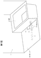
第7図の通り、浴室1の床は浴槽パン(図示略)と洗い場パン2とによって構成され、該浴槽パン上に浴槽3が設置されている。洗い場パン2の浴槽3側には排水枡4が設けられている。該排水枡4は洗い場パン2と一体に凹み状に形成されている。この排水枡4の上面には排水目皿5が装着されている。
As shown in FIG. 7, the floor of the bathroom 1 is composed of a bathtub pan (not shown) and a washing pan 2, and the bathtub 3 is installed on the bathtub pan. A drainage basin 4 is provided on the bathtub 3 side of the washing area pan 2. The drainage basin 4 is formed in a recessed shape integrally with the washing place pan 2. A
これらの浴槽パンの排水口及び洗い場パン2の排水枡4に対し、下側から排水トラップ10が連結されている。
A
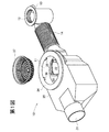
第1,2図に示すように、排水トラップ10の長手方向の略中央の上面には、洗い場パン2からの排水が排水枡4を通り流入する洗い場排水受入口11が設けられている。排水トラップ10の長手方向一端側の上面には、浴槽3からの排水が流入する浴槽排水流入口12が設けられ、その近傍には浴槽パンからの排水が流入する浴槽パン排水流入口13が設けられている。
As shown in FIGS. 1 and 2, a washing place
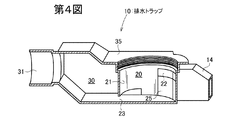
また、この排水トラップ10の他端側には、該排水トラップ10内に流入した水が流出する流出口31が設けられている。この流出口31に排水管6(第7図)が接続されている。
Further, an
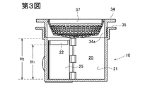
この排水トラップ10内には、洗い場排水受入口11の下側に受入室20が設けられている。この受入室20は、円筒状の周壁21によって囲まれている。周壁21の浴槽排水流入口12側の上部に、受入室20内に浴槽排水を接線方向に流入させるための導入口22が設けられている。この実施の形態では、導入口22は周壁21の周方向に延在した長方形状となっている。なお、第1図には、この導入口22に対し周壁21の内周面側から重なるフラップ弁22fが示されている。(第2図では図示略。)このフラップ弁22fを設けることにより、受入室20からダクト部14側への逆流が防止される。
In the
周壁21の流出口31側にあっては、周壁21の下端と排水トラップ10の底面との間に排出口23が設けられている。導入口22と浴槽排水流入口12とはダクト部14を介して連通している。周壁21の流出口31側と流出口31との間に封水室30が設けられている。流出口31のレベルは封水室30の底面よりも上位となっており、封水室30内には流出口31の下面レベルにまで封水が溜る。周壁21の流出口31側は、その下部がこの封水中に没する上下方向長さを有している。
On the
洗い場排水受入口11にはトラップ取付フランジ34が螺着されており、本体側の上面部35と該フランジ34との間で、排水升4の底部のトラップ取付用開口の縁部をパッキンを介して挟持することにより排水トラップ10が洗い場パン2に固着される。
A
このトラップ取付フランジ34の内周面の凸部36に係止させてヘアキャッチャー37が該トラップ取付フランジ34に内嵌状に着脱可能に装着されている。
A
なお、この実施の形態では、周壁21の導入口22の下側は着脱可能な小プレート25にて構成されている。この小プレート25を外すと、受入室20からダクト部14内をメンテナンスすることができる。
In this embodiment, the lower side of the
第3図の通り、受入室20の底面から導入口22の下縁までの高さH1は、該底面からヘアキャッチャー37の下端までの高さH2の50〜90%特に70〜80%程度であることが好ましい。
As shown in FIG. 3, the height H 1 from the bottom surface of the
次に、この排水トラップ10の作動について説明する。
Next, the operation of the
洗い場パン2からの排水は、排水枡4及び洗い場排水受入口11を通って受入室20に流入し、排出口23、封水室30及び流出口31から排水管6に流出する。洗い場排水や浴槽排水の流出が停止すると、受入室20及び封水室30内には、封水が残り、この封水に周壁21の下端が没するので、排水管6の臭気が洗い場排水受入口11から浴室内に逆流することが防止される。
Drainage from the washing basin 2 flows into the receiving
浴槽3からの排水は、浴槽排水流入口12及びダクト部14を通り、導入口22から受入室20内へ接線方向に流出するため、受入室20内に旋回流が形成されるようになる。また、この浴槽排水の流入により受入室20内の水位が上昇し、ヘアキャッチャー37が旋回流に浸漬され、ヘアキャッチャー37内の毛髪などのゴミがヘアキャッチャー37の中心に集められる。これにより、ゴミを摘んで捨てることができるようになる。また、ヘアキャッチャー37の内外面が旋回流に浸漬されて浄化され、ヌメリ等が除去される。
Since the drainage from the bathtub 3 passes through the
この実施の形態では、導入口22が受入室20の上部にのみ設けられており、受入室20内の上部、すなわち、ヘアキャッチャー37付近に強力な旋回流が形成される。これにより、ヘアキャッチャー37内のゴミが効率よく中心付近に集められると共に、ヘアキャッチャー37が強力な旋回流によって洗浄される。なお、浴槽排水の水位が低いときでも受入室の旋回流が十分に強いものとなる。
In this embodiment, the
また、この実施の形態では、ダクト部14が受入室20の略接線方向に直線状に延在しているので、浴槽排水が、その水勢をそがれることなく導入口22から受入室20内に流入するので、これによっても受入室20内の旋回流が強力なものとなる。
Moreover, in this embodiment, since the
この排水トラップでは、導入口22が受入室20内の上部に位置しているので、洗い場から多量の水が受入室20内に流れ込んできても、浴槽排水流入口12側への逆流が防止される。
In this drainage trap, since the
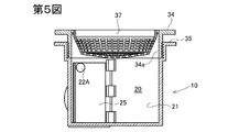
上記実施の形態では、導入口22は周方向に延在した長方形状となっているが、周方向に長い長円形状であってもよい。また、第5図に示す円形の導入口22Aや、第6図に示す正方形状の導入口22Bであってもよい。第5図及び第6図は第3図と同一部分の断面図であり、その他の構成は第3図と同一である。
In the above embodiment, the
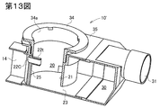
導入口のその他の形状例について第12図〜第14図を参照して説明する。なお、第12図〜第14図の排水トラップ10’は上記排水トラップ10と左右が逆となっているが、導入口の形状以外の構成は排水トラップ10と同一であり、同一符号は同一部分を示している。第12図では、導入口22Cは小プレート25の上部において一文字状の水平開口として設けられている。第13図及び第14図では、この導入口22Cの受入室20側に連なる筒状部22tが設けられており、浴槽排水が受入室20からダクト部14側へ逆流することを防止している。なお、第14図では、導入口22Cのダクト部14側の縁部22rを丸みを帯びたR形状とし、これにより、浴槽排水の導入口22Cへの流入抵抗を減少させている。
Other examples of the shape of the inlet will be described with reference to FIGS. Although the drain trap 10 'in FIGS. 12 to 14 is opposite to the
なお、上記実施の形態では、第2,3図、第5,6図の通り周壁21の内周面とトラップ取付フランジ34の筒部内周面34aが同一径であり、面一状となっている。そのため、周壁21の内周面に沿う旋回流がフランジ34の筒部内周面にも沿ってスムーズに旋回する。
In the above embodiment, as shown in FIGS. 2, 3, 5 and 6, the inner peripheral surface of the
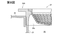
上記実施の形態では、フランジ34の内周面34aは上下方向の全体にわたって実質的に同一径となっているが、第8図のフランジ34Aのように、内周面34aの上部が上方ほど縮径する滑らかに湾曲したテーパ状となっていてもよい。この場合、旋回流がフランジ34Aに沿ってスムーズにヘアキャッチャー37に流れ込む。
In the above embodiment, the inner
フランジ34又は34Aの下端と周壁21の上端との間に隙間があくときには、第9図のようにゴムパッキンなどよりなるスペーサ39を介在させてもよい。
When there is a gap between the lower end of the
第10図のように、周壁21の内径がフランジ34Bの下部の内径よりも大きいときには、フランジ34Bの内周面34aの下部を下方ほど拡径するテーパ形状とし、内周面34aの下端と周壁21の内周面との段差を小さくするのが好ましい。
As shown in FIG. 10, when the inner diameter of the
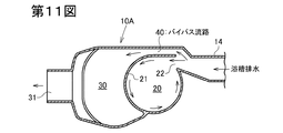
上記実施の形態では浴槽排水の全量が受入室20内に流入する構成となっているが、浴槽排水の一部は受入室20を迂回(バイパス)して封水室30へ流れるよう構成してもよい。第11図はその一例に係る排水トラップ10Aを示す水平断面図であり、周壁21の側部に沿ってバイパス流路40が設けられている。第11図の排水トラップ10Aのその他の構成は排水トラップ10と同一である。なお、第11図では、導入口22は浴槽排水の流れの正面に配置され、バイパス流路40の入口は浴槽排水の流れからそれた位置に配置されているため、浴槽排水は導入口22の方に多く流れこむ。そのため、浴槽水位が低いときにも排水は効率的に導入口22から受入室20に流れこみ、強力な旋回流となる。
In the above embodiment, the total amount of the bathtub drainage flows into the receiving
2 洗い場パン
3 浴槽
4 排水枡
10,10’,10A 排水トラップ
11 洗い場排水受入口
12 浴槽排水流入口
13 浴槽パン排水口流入口
14 ダクト部
20 受入室
21 周壁
22,22A,22B,22C,22D 導入口
23 排出口
25 小プレート
30 封水室
31 流出口
34,34A,34B フランジ
37 ヘアキャッチャー
40 バイパス流路
2 Washing area pan 3 Bathtub 4
Claims (3)
該受入口に配置されたヘアキャッチャーと、
該受入室を囲む周壁に設けられた導入口と、
該導入口に連通した浴槽排水流入口と、
該受入室の下部に設けられた排出口と、
該排出口に連通した流出口と
を備え、該導入口から受入室内に浴槽排水が接線方向に流入し、受入室に旋回流が形成される浴槽及び洗い場用の排水トラップにおいて、
該導入口は該受入室の上部に設けられていることを特徴とする排水トラップ。 A reception room where washroom drainage flows from the reception port;
A hair catcher disposed at the entrance;
An inlet provided in a peripheral wall surrounding the receiving chamber;
A bathtub drainage inlet communicating with the inlet;
An outlet provided at the bottom of the receiving chamber;
A drainage trap for a tub and a washing place, in which a tub drainage flows in a tangential direction from the introduction port into the receiving chamber, and a swirling flow is formed in the receiving chamber.
The drainage trap, wherein the introduction port is provided in an upper part of the receiving chamber.
Priority Applications (1)
| Application Number | Priority Date | Filing Date | Title |
|---|---|---|---|
| JP2011036144A JP5703824B2 (en) | 2011-02-22 | 2011-02-22 | Drain trap |
Applications Claiming Priority (1)
| Application Number | Priority Date | Filing Date | Title |
|---|---|---|---|
| JP2011036144A JP5703824B2 (en) | 2011-02-22 | 2011-02-22 | Drain trap |
Publications (2)
| Publication Number | Publication Date |
|---|---|
| JP2012172422A true JP2012172422A (en) | 2012-09-10 |
| JP5703824B2 JP5703824B2 (en) | 2015-04-22 |
Family
ID=46975598
Family Applications (1)
| Application Number | Title | Priority Date | Filing Date |
|---|---|---|---|
| JP2011036144A Active JP5703824B2 (en) | 2011-02-22 | 2011-02-22 | Drain trap |
Country Status (1)
| Country | Link |
|---|---|
| JP (1) | JP5703824B2 (en) |
Cited By (4)
| Publication number | Priority date | Publication date | Assignee | Title |
|---|---|---|---|---|
| JP2017179880A (en) * | 2016-03-30 | 2017-10-05 | Toto株式会社 | Drain trap |
| JP2017179881A (en) * | 2016-03-30 | 2017-10-05 | Toto株式会社 | Drain trap |
| JP2017179879A (en) * | 2016-03-30 | 2017-10-05 | Toto株式会社 | Drain trap |
| JP2017179878A (en) * | 2016-03-30 | 2017-10-05 | Toto株式会社 | Drain trap |
Citations (4)
| Publication number | Priority date | Publication date | Assignee | Title |
|---|---|---|---|---|
| JP2003313914A (en) * | 2002-04-24 | 2003-11-06 | Maruichi Kk | Drain trap |
| JP2005171707A (en) * | 2003-12-15 | 2005-06-30 | Matsushita Electric Works Ltd | Drain trap |
| JP2009167589A (en) * | 2008-01-10 | 2009-07-30 | Inax Corp | Drain trap |
| JP2009203784A (en) * | 2008-02-26 | 2009-09-10 | Nippon Alpha:Kk | Drainage trap for bathroom |
-
2011
- 2011-02-22 JP JP2011036144A patent/JP5703824B2/en active Active
Patent Citations (4)
| Publication number | Priority date | Publication date | Assignee | Title |
|---|---|---|---|---|
| JP2003313914A (en) * | 2002-04-24 | 2003-11-06 | Maruichi Kk | Drain trap |
| JP2005171707A (en) * | 2003-12-15 | 2005-06-30 | Matsushita Electric Works Ltd | Drain trap |
| JP2009167589A (en) * | 2008-01-10 | 2009-07-30 | Inax Corp | Drain trap |
| JP2009203784A (en) * | 2008-02-26 | 2009-09-10 | Nippon Alpha:Kk | Drainage trap for bathroom |
Cited By (4)
| Publication number | Priority date | Publication date | Assignee | Title |
|---|---|---|---|---|
| JP2017179880A (en) * | 2016-03-30 | 2017-10-05 | Toto株式会社 | Drain trap |
| JP2017179881A (en) * | 2016-03-30 | 2017-10-05 | Toto株式会社 | Drain trap |
| JP2017179879A (en) * | 2016-03-30 | 2017-10-05 | Toto株式会社 | Drain trap |
| JP2017179878A (en) * | 2016-03-30 | 2017-10-05 | Toto株式会社 | Drain trap |
Also Published As
| Publication number | Publication date |
|---|---|
| JP5703824B2 (en) | 2015-04-22 |
Similar Documents
| Publication | Publication Date | Title |
|---|---|---|
| JP4895760B2 (en) | Hair catcher | |
| JP5703824B2 (en) | Drain trap | |
| JP4781226B2 (en) | Drain trap and bathroom with this drain trap | |
| JP4709981B2 (en) | Drain trap | |
| JP5245364B2 (en) | Bathroom drainage equipment | |
| JP5446123B2 (en) | Drain trap | |
| JP5929278B2 (en) | Drain trap | |
| JP5733010B2 (en) | Drain trap | |
| JP6454841B2 (en) | Drainage structure with collecting member | |
| JP5423059B2 (en) | Bathroom drainage equipment | |
| JP4757037B2 (en) | Drain trap | |
| JP2009167589A (en) | Drain trap | |
| JP3879743B2 (en) | Drain trap | |
| JP6326578B2 (en) | Drainage member | |
| CN111139911A (en) | Squatting pan | |
| JP5597794B2 (en) | Tank body and tank drainer | |
| JP7249495B2 (en) | Drain joint with perforated plate | |
| JP5685830B2 (en) | Drain trap | |
| JP6303098B2 (en) | Hair catcher | |
| CN212104411U (en) | Squatting pan | |
| JP2009264053A (en) | Drainage trap | |
| JP2009167591A (en) | Drain trap | |
| JP5224772B2 (en) | Drainage trap and drainage method | |
| JP6019286B2 (en) | Bathroom drain piping | |
| JP5245398B2 (en) | Drain trap |
Legal Events
| Date | Code | Title | Description |
|---|---|---|---|
| A621 | Written request for application examination |
Free format text: JAPANESE INTERMEDIATE CODE: A621 Effective date: 20130924 |
|
| A977 | Report on retrieval |
Free format text: JAPANESE INTERMEDIATE CODE: A971007 Effective date: 20140530 |
|
| A131 | Notification of reasons for refusal |
Free format text: JAPANESE INTERMEDIATE CODE: A131 Effective date: 20140603 |
|
| A521 | Written amendment |
Free format text: JAPANESE INTERMEDIATE CODE: A523 Effective date: 20140725 |
|
| TRDD | Decision of grant or rejection written | ||
| A01 | Written decision to grant a patent or to grant a registration (utility model) |
Free format text: JAPANESE INTERMEDIATE CODE: A01 Effective date: 20150127 |
|
| A61 | First payment of annual fees (during grant procedure) |
Free format text: JAPANESE INTERMEDIATE CODE: A61 Effective date: 20150209 |
|
| R150 | Certificate of patent or registration of utility model |
Ref document number: 5703824 Country of ref document: JP Free format text: JAPANESE INTERMEDIATE CODE: R150 |
|
| S111 | Request for change of ownership or part of ownership |
Free format text: JAPANESE INTERMEDIATE CODE: R313111 |
|
| R350 | Written notification of registration of transfer |
Free format text: JAPANESE INTERMEDIATE CODE: R350 |