JP2012169727A - Image signal processor and image signal processing method - Google Patents
Image signal processor and image signal processing method Download PDFInfo
- Publication number
- JP2012169727A JP2012169727A JP2011026831A JP2011026831A JP2012169727A JP 2012169727 A JP2012169727 A JP 2012169727A JP 2011026831 A JP2011026831 A JP 2011026831A JP 2011026831 A JP2011026831 A JP 2011026831A JP 2012169727 A JP2012169727 A JP 2012169727A
- Authority
- JP
- Japan
- Prior art keywords
- synchronization
- video
- frame
- display
- signal
- Prior art date
- Legal status (The legal status is an assumption and is not a legal conclusion. Google has not performed a legal analysis and makes no representation as to the accuracy of the status listed.)
- Withdrawn
Links
Images


Classifications
-
- H—ELECTRICITY
- H04—ELECTRIC COMMUNICATION TECHNIQUE
- H04N—PICTORIAL COMMUNICATION, e.g. TELEVISION
- H04N7/00—Television systems
- H04N7/01—Conversion of standards, e.g. involving analogue television standards or digital television standards processed at pixel level
- H04N7/0127—Conversion of standards, e.g. involving analogue television standards or digital television standards processed at pixel level by changing the field or frame frequency of the incoming video signal, e.g. frame rate converter
-
- G—PHYSICS
- G09—EDUCATION; CRYPTOGRAPHY; DISPLAY; ADVERTISING; SEALS
- G09G—ARRANGEMENTS OR CIRCUITS FOR CONTROL OF INDICATING DEVICES USING STATIC MEANS TO PRESENT VARIABLE INFORMATION
- G09G5/00—Control arrangements or circuits for visual indicators common to cathode-ray tube indicators and other visual indicators
- G09G5/003—Details of a display terminal, the details relating to the control arrangement of the display terminal and to the interfaces thereto
- G09G5/006—Details of the interface to the display terminal
-
- G—PHYSICS
- G09—EDUCATION; CRYPTOGRAPHY; DISPLAY; ADVERTISING; SEALS
- G09G—ARRANGEMENTS OR CIRCUITS FOR CONTROL OF INDICATING DEVICES USING STATIC MEANS TO PRESENT VARIABLE INFORMATION
- G09G2340/00—Aspects of display data processing
- G09G2340/04—Changes in size, position or resolution of an image
- G09G2340/0442—Handling or displaying different aspect ratios, or changing the aspect ratio
-
- G—PHYSICS
- G09—EDUCATION; CRYPTOGRAPHY; DISPLAY; ADVERTISING; SEALS
- G09G—ARRANGEMENTS OR CIRCUITS FOR CONTROL OF INDICATING DEVICES USING STATIC MEANS TO PRESENT VARIABLE INFORMATION
- G09G2360/00—Aspects of the architecture of display systems
- G09G2360/12—Frame memory handling
-
- G—PHYSICS
- G09—EDUCATION; CRYPTOGRAPHY; DISPLAY; ADVERTISING; SEALS
- G09G—ARRANGEMENTS OR CIRCUITS FOR CONTROL OF INDICATING DEVICES USING STATIC MEANS TO PRESENT VARIABLE INFORMATION
- G09G2360/00—Aspects of the architecture of display systems
- G09G2360/18—Use of a frame buffer in a display terminal, inclusive of the display panel
Landscapes
- Engineering & Computer Science (AREA)
- Multimedia (AREA)
- Signal Processing (AREA)
- Physics & Mathematics (AREA)
- Computer Hardware Design (AREA)
- General Physics & Mathematics (AREA)
- Theoretical Computer Science (AREA)
- Television Systems (AREA)
- Two-Way Televisions, Distribution Of Moving Picture Or The Like (AREA)
- Controls And Circuits For Display Device (AREA)
Abstract
【課題】複数の映像を同一ディスプレイ上に多画面表示する際に、フレームシンクロ処理により生じる、ユーザに違和感を与える映像の動きのガタツキを目立たなくさせる。
【解決手段】フレームシンクロ部は、リピート、スキップに好適なシーンを検出するシンクロタイミング検出部と、シンクロタイミング検出部から通知されたタイミングに基づいてフレームメモリへの書き込み、読み出しアドレスを制御するアドレス制御部を備えることにより、フレームメモリから読み出すフレームをリピート、スキップすることタイミングを調整する。
また、フレームシンクロ部は、時間的に連続する複数のフレームから中間位相の補間フレームを生成する補間フレーム生成部を備え、リピート、スキップされる周辺のフレームを、フレーム間隔が時間的にほぼ均等となるような補間フレームに置き換える。
【選択図】図1When a plurality of images are displayed on the same display on a multi-screen, the motion fluctuation of the images that causes discomfort to the user caused by frame synchronization processing is made inconspicuous.
A frame synchronization unit detects a scene suitable for repeat and skip, and an address control for controlling a write / read address to a frame memory based on a timing notified from the synchronization timing detection unit By providing the unit, the timing for repeating and skipping the frame read from the frame memory is adjusted.
In addition, the frame synchronization unit includes an interpolation frame generation unit that generates an intermediate-phase interpolation frame from a plurality of temporally continuous frames, and the frame intervals of repeat and skipped peripheral frames are substantially equal in time. Replace with an interpolated frame.
[Selection] Figure 1
Description
本発明は、複数の映像を同一ディスプレイ上に多画面表示する際に、映像の動きを滑らかにする映像信号処理装置および方法に関する。 The present invention relates to a video signal processing apparatus and method for smoothing the motion of a video when a plurality of videos are displayed on a multi-screen on the same display.
近年、DTV(デジタルテレビ)等において、複数の映像を同一ディスプレイ上に同時に表示する多画面表示が一般的になりつつある。ディスプレイの大画面、高精細化も一助となり、ユーザは多チャンネル同時表示や、放送と録画機器、または、外部ネットワークを通じて提供されるコンテンツの再生等の同時表示などを楽しむことが可能となる。 In recent years, in a DTV (digital television) or the like, multi-screen display that simultaneously displays a plurality of videos on the same display is becoming common. The large screen and high definition of the display also help, and the user can enjoy simultaneous display such as multi-channel simultaneous display and playback of content provided through broadcasting and recording equipment or an external network.
複数の映像ソースを多画面表示する場合に、その画面表示のために用いる同期信号が一つであることから、DTVでは複数の映像ソースのいずれかの垂直同期信号に同期して映像を表示する必要がある。この際に選択する映像ソースとして、画面サイズが最も大きい、ユーザが最も注視したい映像(以下、主映像と記す)を選択する。この主映像の垂直同期信号(以下、V同期と記す)を基準として、他の映像(以下、副映像と記す)を表示させる必要がある。PC等では、フリーラン生成したV同期を基準に全ての映像を表示させる場合もある(特許文献1、特許文献2)。
When a plurality of video sources are displayed on a multi-screen, only one synchronization signal is used to display the screen. Therefore, in DTV, video is displayed in synchronization with one of the vertical synchronization signals of the plurality of video sources. There is a need. As the video source to be selected at this time, the video having the largest screen size and the video that the user wants to watch most (hereinafter referred to as the main video) is selected. It is necessary to display another video (hereinafter referred to as sub-video) on the basis of the vertical synchronization signal (hereinafter referred to as V-sync) of the main video. In a PC or the like, there are cases where all videos are displayed based on V synchronization generated by free-running (
このとき、主映像と副映像のV同期は互いに異なる周波数であることから、副映像を主映像に同期させて表示するためにフレームシンクロナイズ(以下、フレームシンクロと記す)と呼ばれる処理を行うのが一般的である。フレームシンクロナイズにおいて、主映像のV同期に従って、副映像のフレームを読み出すことで副映像を同調させる。この結果、一定周期で副映像のフレームが間引かれて(スキップ処理)表示したり、繰返して(リピート処理)表示したりする。例えば、主映像のV同期が59.94Hzであり、副映像のV同期が60.00Hzの場合、副映像は約1000フレーム(約16.7秒)毎にフレームが1枚スキップされる。 At this time, since the V synchronization of the main video and the sub video has different frequencies, a process called frame synchronization (hereinafter referred to as frame synchronization) is performed in order to display the sub video in synchronization with the main video. It is common. In frame synchronization, the sub-picture is synchronized by reading out the sub-picture frame in accordance with V synchronization of the main picture. As a result, the sub-picture frames are thinned out (skip processing) or displayed repeatedly (repeat processing) at regular intervals. For example, when V synchronization of the main video is 59.94 Hz and V synchronization of the sub video is 60.00 Hz, the sub video skips one frame every about 1000 frames (about 16.7 seconds).
しかしながら、このフレームシンクロ処理は、一定周期でフレームをスキップしたり、リピートしたりして表示するため、表示される映像のフレーム再生が時間的に不連続になることとなる。例えば、カメラが一定期間パンしたり、チルトしたりするような場面では、映像の動きにガタツキ(ジャダー)が生じてしまい、ユーザに違和感を与え、視聴品位を損なうという課題がある。 However, since this frame synchronization process is performed by skipping or repeating frames at a fixed period, frame reproduction of the displayed video is discontinuous in time. For example, in a scene in which the camera pans or tilts for a certain period of time, there is a problem in that the motion of the video is unstable (judder), giving the user a sense of incongruity and impairing viewing quality.
そこで本発明は、複数の映像を同時に表示する、多画面表示する場合において、フレームシンクロ処理によるジャダーを軽減し、スムースで高品位な映像表示を行うことを目的とするものである。 Therefore, the present invention has an object to reduce the judder caused by the frame synchronization process and to display a smooth and high-quality image when a plurality of images are displayed simultaneously or in a multi-screen display.
上記課題を解決するため、本発明における映像信号処理装置は、複数の映像を画面に同時に表示するための表示用画面を生成する映像信号処理装置であって、複数の前記映像の映像信号を入力する映像入力部と、フリーラン垂直同期信号、または、複数の前記映像信号のうちの一つの映像信号における垂直同期信号を基準として、前記表示用画面を表示するための同期信号である表示同期信号を生成する表示同期生成部と、前記映像入力部から入力した複数の前記映像信号を、前記表示同期信号に同期して出力するフレームシンクロ部と、前記フレームシンクロ部から出力した複数の映像信号を合成して前記表示用画面として生成する多画面合成部とを備え、前記フレームシンクロ部は、複数の前記映像信号のうち、前記表示同期信号とは同期ずれが発生する映像信号に対して、同期ずれを解消する適当な期間を判定するシンクロタイミング検出部を備え、前記シンクロタイミング検出部で判定した期間において、前記表示同期信号とは同期ずれが発生する映像信号に対して、同じ時刻のフレームを繰り返して出力するか、または、フレームを間引いて出力することで同期ずれを解消する。 In order to solve the above problems, a video signal processing apparatus according to the present invention is a video signal processing apparatus that generates a display screen for simultaneously displaying a plurality of videos on a screen, and inputs a plurality of video signals of the videos. Display synchronization signal that is a synchronization signal for displaying the display screen on the basis of a video input unit and a free-run vertical synchronization signal or a vertical synchronization signal in one of the plurality of video signals. A display synchronization generation unit that generates a plurality of video signals input from the video input unit, a frame synchronization unit that outputs in synchronization with the display synchronization signal, and a plurality of video signals output from the frame synchronization unit. A multi-screen composition unit that synthesizes and generates the display screen, and the frame synchronization unit is the same as the display synchronization signal among the plurality of video signals. A synchronization timing detection unit that determines an appropriate period for eliminating the synchronization shift is provided for a video signal in which a shift occurs, and a synchronization shift occurs with the display synchronization signal during the period determined by the synchronization timing detection unit. For the video signal, the frame at the same time is repeatedly output or the frame is thinned and output to eliminate the synchronization shift.
また、本発明の映像信号処理装置は、複数の映像を画面に同時に表示するための表示用画面を生成する映像信号処理装置であって、複数の前記映像の映像信号を入力する映像入力部と、フリーラン垂直同期信号、または、複数の前記映像信号のうちの一つの映像信号における垂直同期信号を基準として、前記表示用画面を表示するための同期信号である表示同期信号を生成する表示同期生成部と、前記映像入力部から入力した複数の前記映像信号を、前記表示同期信号に同期して出力するフレームシンクロ部と、前記フレームシンクロ部から出力した複数の映像信号を合成して前記表示用画面として生成する多画面合成部とを備え、前記フレームシンクロ部は、複数の前記映像信号のうち、前記表示同期信号とは同期ずれが発生する映像信号に対して、時間的に連続する複数のフレームから中間位相の補間フレームを生成する補間フレーム生成部を備え、前記表示同期信号とは同期ずれが発生する映像信号に対して、同期ずれを解消する期間においては、当該映像信号に代わり前記補間フレーム生成部で生成した中間フレームに置き換えることで同期ずれを解消する。 The video signal processing apparatus of the present invention is a video signal processing apparatus that generates a display screen for simultaneously displaying a plurality of videos on a screen, and a video input unit that inputs a plurality of video signals of the video, Display synchronization that generates a display synchronization signal, which is a synchronization signal for displaying the display screen, based on a free-running vertical synchronization signal or a vertical synchronization signal in one of the plurality of video signals. A generating unit; a frame synchronization unit that outputs the plurality of video signals input from the video input unit in synchronization with the display synchronization signal; and a combination of the plurality of video signals output from the frame synchronization unit. A multi-screen synthesis unit that generates a video screen, wherein the frame synchronization unit is a video signal that is out of synchronization with the display synchronization signal among the plurality of video signals On the other hand, an interpolation frame generation unit that generates an intermediate-phase interpolation frame from a plurality of temporally continuous frames, and a period for eliminating the synchronization shift with respect to the video signal in which the synchronization shift from the display synchronization signal occurs In this case, the synchronization shift is eliminated by replacing the video signal with the intermediate frame generated by the interpolation frame generation unit.
本発明によれば、複数の映像を多画面表示する場合において、フレームシンクロ処理によるジャダーを軽減し、スムースで高品位な映像表示が可能となる。 According to the present invention, when a plurality of videos are displayed on a multi-screen, judder due to frame synchronization processing is reduced, and a smooth and high-quality video display is possible.
以下、本発明の実施の形態について、図面を参照しながら説明する。 Hereinafter, embodiments of the present invention will be described with reference to the drawings.
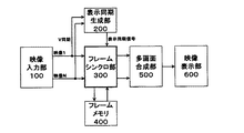
図1に示すように、実施の形態における映像信号処理装置は、映像入力部100、表示同期生成部200、フレームシンクロ部300、フレームメモリ400、多画面合成部500、映像表示部600で構成される。
As shown in FIG. 1, the video signal processing apparatus according to the embodiment includes a
複数の映像信号は、映像入力部100から入力され、表示同期生成部200、フレームシンクロ部300に出力される。
A plurality of video signals are input from the
表示同期生成部200は、入力した映像信号を表示するための表示同期信号である表示V同期を生成する。この表示V同期信号としては、入力した複数の映像信号のうちの一つの映像信号から、その垂直信号同期(Vsync同期、以降V同期と表す)を用いることができる。また、クロック発生器(図示せず)により可変となるクロックを発生して、所定の表示同期信号の周波数(例えば60Hz)に至るまで、クロックを徐々に変化させたものを、表示V同期信号として用いることができる。このようにクロックを徐々に変化して発生させた同期信号を、フリーランV同期と呼ぶ。
The display
フレームシンクロ部300は、映像入力部100から入力された複数の映像信号を、フレームメモリ400に一旦格納し、表示同期生成部200で生成された表示V同期に同期させて、フレームメモリ400に格納された複数の映像信号を読み出す。フレームシンクロ部300は、読み出した映像信号を多画面合成部500へ出力する。
The
多画面合成部500は、フレームシンクロ部300から出力された複数の映像信号を、表示画面上に配置し、合成した映像を映像表示部600へ出力する。
The
映像表示部600は、多画面合成部500から出力された映像を表示する。
The
次に、フレームシンクロ部300について詳しく説明する。
Next, the
(実施の形態1)
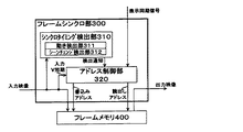
図2は、実施の形態1におけるフレームシンクロ部300の構成図である。
(Embodiment 1)
FIG. 2 is a configuration diagram of the
フレームシンクロ部300は、シンクロタイミング検出部310と、アドレス制御部320とで構成される。シンクロタイミング検出部310は、映像の動き量を検出する動き検出部311と、映像の切り替わりを検出するシーンチェンジ検出部312とを備える。
The
フレームシンクロ部300は、フレームメモリ400に格納された、入力された映像信号それぞれに対して、そのフレームを繰り返して読み出す処理(リピート処理)や、映像信号を飛び越す処理(スキップ処理)をすることにより、入力された映像信号を読み出す。入力された映像信号を読み出すタイミングは、表示同期信号に映像を同期させる部分であって、リピート処理やスキップ処理に好適なシーンで行われる。
The
シンクロタイミング検出部310は、リピート処理や、スキップ処理に好適なシーンを検出する。 The synchronization timing detection unit 310 detects a scene suitable for repeat processing and skip processing.
アドレス制御部320は、シンクロタイミング検出部310から通知されたタイミングに基づいてフレームメモリ400への書き込みや、読み出しのアドレスを制御する。
The
次に、上述した構成について具体例を挙げて、その動作を後述する。 Next, the operation of the above-described configuration will be described later with a specific example.
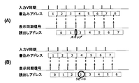
その前に、図3を用いて従来のフレームシンクロの動作を説明する。図3は、フレームメモリへの書き込み、読み出しアドレスの従来の制御を示した説明図である。 Before that, the operation of the conventional frame sync will be described with reference to FIG. FIG. 3 is an explanatory diagram showing conventional control of write and read addresses to the frame memory.
従来のアドレス制御部(図示せず)は、入力となる映像信号のV同期と、画面表示するための表示用同期信号とを受ける。入力となる映像信号は、書き込みアドレスに従い、フレームメモリに書き込まれる。その際に、入力V同期に同期して書き込みアドレスをカウントアップし、バッファ可能なフレーム数を超えた時点で書き込みアドレスを0にリセットする。 A conventional address control unit (not shown) receives V synchronization of an input video signal and a display synchronization signal for screen display. The input video signal is written to the frame memory according to the write address. At this time, the write address is counted up in synchronization with the input V synchronization, and the write address is reset to 0 when the number of frames that can be buffered is exceeded.
一方、表示するための映像信号は、読み出しアドレスに従って、フレームメモリから読み出される。その際に、読み出しアドレスは、(表示用同期信号のタイミングにおける書き込みアドレス)−(所定の位相差)として求める。図3の場合には、位相差を1としている。 On the other hand, the video signal to be displayed is read from the frame memory according to the read address. At this time, the read address is obtained as (write address at the timing of the display synchronization signal) − (predetermined phase difference). In the case of FIG. 3, the phase difference is set to 1.
このように、書き込みアドレスと、読み出しアドレスを制御することで、入力した映像信号を画面表示するための表示用同期信号に同期させて表示させる。 In this way, by controlling the write address and the read address, the input video signal is displayed in synchronization with the display synchronization signal for screen display.
従来のアドレス制御を行うことにより、入力V同期と表示同期信号との周波数が同じである場合は、同期して出力させることが可能だが、入力V同期と表示用同期信号と間の周波数に差がある場合には、入力された映像信号を飛び超すスキップや、反対に、入力された映像信号が繰り返して表示されるリピートが発生する。 By performing the conventional address control, if the frequency of the input V synchronization and the display synchronization signal is the same, it is possible to output in synchronization, but there is a difference in the frequency between the input V synchronization and the display synchronization signal. If there is, there is a skip in which the input video signal is skipped, or a repeat in which the input video signal is repeatedly displayed.
例えば、入力V同期よりも表示用同期信号の周波数が遅い場合を図3(A)に示す。図3(A)では、書き込みアドレス「2」を書き込み途中で発生した表示同期信号に対して、フレーム「1」を読み込みアドレスで指定されている。続く、書き込みアドレス「3」で書き込み、さらに書き込みアドレス「4」で書き込みをしている途中で表示同期信号が発生している。このため、書き込みアドレス「4」の位相差が1である、フレーム「3」を読み込みアドレスとして指定する。このように入力された映像信号の「2」のフレームが飛び越されて読み出されるフレームスキップが生じる。 For example, FIG. 3A shows a case where the frequency of the display synchronization signal is slower than the input V synchronization. In FIG. 3A, the frame “1” is designated by the read address for the display synchronization signal generated during the writing of the write address “2”. Subsequently, a display synchronization signal is generated during writing at the write address “3” and further at the write address “4”. Therefore, the frame “3” in which the phase difference of the write address “4” is 1 is designated as the read address. Thus, a frame skip occurs in which the frame “2” of the input video signal is skipped and read out.
また、入力V同期よりも表示用同期信号の周波数が早い場合を図3(B)に示す。図3(B)では、書き込みアドレス「3」を書き込み途中に、表示同期信号が2回発生している。このため、2回の表示同期信号に対応する読み出しアドレスはフレーム「2」を指定する。このように入力された映像信号の「2」のフレームが繰り返されて読み出されるフレームリピートが生ずる。 FIG. 3B shows a case where the frequency of the display synchronization signal is faster than the input V synchronization. In FIG. 3B, the display synchronization signal is generated twice while the write address “3” is being written. For this reason, the frame “2” is designated as the read address corresponding to the two display synchronization signals. In this manner, frame repeat is generated in which the “2” frame of the input video signal is repeatedly read out.
以上のように、従来のアドレス制御では、ジャダー(judder)と呼ばれる、同じフレームが繰り返されたり、フレームがスキップされることによる飛びが発生したりすることが、一定の期間ごとに繰り返して生じる。このため、表示される場面によって、ユーザは違和感を感じることがある。 As described above, in the conventional address control, the same frame, called judder, is repeatedly generated or skipped by skipping a frame at regular intervals. For this reason, the user may feel uncomfortable depending on the displayed scene.
映像が静止している場面、または動きの極端に激しい場面、または場面が変化する(シーンチェンジの)際のブラックアウトや、ホワイトアウト等の発生する場面では、ユーザによってジャダーが知覚されにくい。 Judder is not easily perceived by the user in a scene where the image is stationary, a scene where the motion is extremely intense, or a scene where blackout or whiteout occurs when the scene changes (scene change).
そこで本実施の形態では、このことに着目し、これらの場面でフレームを繰り返して再生させるリピート処理や、フレームを飛び越して再生させるスキップ処理による、ジャダーを発生させることにより、ユーザに知覚されにくくすることを特徴とする。 Therefore, in this embodiment, paying attention to this, it is made difficult to perceive by the user by generating judder by repeat processing for repeatedly playing frames in these scenes or skip processing for skipping frames. It is characterized by that.
動き検出部311およびシーンチェンジ検出部312は、映像が静止している静止場面、または、動きの極端に激しい場面、または、シーンチェンジを検出する。 The motion detection unit 311 and the scene change detection unit 312 detect a still scene in which a video is still, a scene with extremely intense motion, or a scene change.
静止場面か、または、動きの極端に激しい場面かの区別としては、次のように指定を行う。入力映像の各フレームの時間的に連続したフレームについて、それぞれのフレームをいくつかの小領域に分割し、対応する分割した小領域の、前後のフレームでの輝度差の総和を求める。この総和が0に近いほど静止シーン、総和が大きいほど動きの極端に激しい場面、または、シーンチェンジとして判断できる。静止シーンと判定するための所定の閾値と、動きの極端に激しい場面やシーンチェンジとして判断するための所定の閾値を設けて、フレーム間の輝度差の総和とそれぞれの閾値とを大小関係することにより、静止シーン、動きの極端に激しい場面やシーンチェンジであるとの判断を行う。また、シーンチェンジの検出は、入力映像のフレーム全体の平均輝度と、入力映像のフレーム以前との数フレームの平均輝度との差が大きくなる部分をシーンチェンジと判定しても構わない。 The distinction between a still scene and a scene with extremely intense movement is specified as follows. With respect to the temporally continuous frames of the input video, each frame is divided into several small areas, and the sum of luminance differences between the preceding and following frames of the corresponding divided small areas is obtained. It can be determined as a still scene as this sum is closer to 0, a scene with extremely intense movement as the sum is larger, or a scene change. Establishing a predetermined threshold for determining a still scene and a predetermined threshold for determining an extremely intense scene or scene change, and the total difference in luminance between frames and the respective thresholds are related in magnitude Thus, it is determined that the scene is a still scene, an extremely intense scene, or a scene change. In the detection of a scene change, a portion where the difference between the average luminance of the entire frame of the input video and the average luminance of several frames before the frame of the input video is large may be determined as a scene change.
シンクロタイミング検出部310は、動き検出部311、シーンチェンジ検出部312で検出した、静止場面、動きの激しい場面、シーンチェンジが発生する場面に、リピート処理、スキップ処理の好適なタイミングとしてアドレス制御部320に通知する。 The synchronization timing detection unit 310 has an address control unit as a suitable timing for repeat processing and skip processing in a still scene, a scene with intense motion, and a scene in which a scene change occurs detected by the motion detection unit 311 and the scene change detection unit 312. 320 is notified.
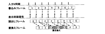
図4は、アドレス制御部320におけるフレームメモリ400への書き込み、および、読み出しアドレスの制御を示した説明図である。図4において、スキップ処理の場合を例示しているが、リピート処理についても同様にできる。
FIG. 4 is an explanatory diagram showing the writing to the frame memory 400 and the control of the reading address in the
図4において、位相差を4としている。また、フレームメモリの大きさも8フレーム分、つまり、アドレスとしては「0」〜「7」まで用意されているものとする。 In FIG. 4, the phase difference is set to 4. It is assumed that the size of the frame memory is 8 frames, that is, addresses “0” to “7” are prepared.
アドレス制御部320で生成する書き込みアドレスは、入力V同期によりカウントアップする。
The write address generated by the
一方、読み出しアドレスは、図4(a)に示すとおり、表示開始時に書き込みアドレスと所定の位相差となるようリセットし、表示V同期によりカウントアップする。書き込みアドレスが「4」で書き込みされた後に、表示同期信号により位相差が4である「0」のフレームを読み出す。 On the other hand, as shown in FIG. 4A, the read address is reset so as to have a predetermined phase difference from the write address at the start of display, and is counted up by display V synchronization. After writing with a write address of “4”, a frame of “0” having a phase difference of 4 is read by the display synchronization signal.
図4(a)の状態から(b)の状態に進む間に、表示同期信号が入力V同期よりも遅れている場合で、途中での位相差調整を行わずに、その遅れ分を累積している状態を示している。図4(b)では、書き込みアドレス「4」で入力された映像信号を書き込んでいる際に、表示同期信号が発生している。ここまで、フレームスキップをせずに読み出しを行っているため位相差が累積され、位相差「4」ではなく位相差「6」となっている。ここで、読み出しアドレスの位相差「6」のままであるのならばフレーム「0」を読み出すことになる。しかしながら、シンクロタイミング検出部310からフレームスキップに好適なシーンであると通知されれば、位相差を解消するようにフレームスキップ処理を行う。 While the display synchronization signal is delayed from the input V synchronization while proceeding from the state shown in FIG. 4A to the state shown in FIG. 4B, the delay is accumulated without adjusting the phase difference in the middle. It shows the state. In FIG. 4B, a display synchronization signal is generated when the video signal input at the write address “4” is being written. Up to this point, since the readout is performed without frame skipping, the phase difference is accumulated, and the phase difference is “6” instead of the phase difference “4”. Here, if the read address phase difference “6” remains, the frame “0” is read out. However, if it is notified from the sync timing detection unit 310 that the scene is suitable for frame skipping, frame skip processing is performed so as to eliminate the phase difference.
今、書き込みアドレスとの位相差「6」であり、所定の位相差「4」より大きいためフレームスキップが可能と判断し、所定の位相差に追い付くまでフレームスキップを行う。図4(b)においては、好適シーン通知がなされている間、位相差を1ずつ詰める処理を行う。つまり、書き込みアドレス「5」で入力された映像信号が書き込まれている間に発生した表示同期信号に応じて、位相差を1つ縮めた位相差「5」であるアドレス「0」を読み込みアドレスとして設定する。続く、書き込みアドレス「6」の期間に発生した表示同期信号に応じて、さらに位相差を1つ縮めた位相差「4」となるアドレス「2」を読み込みアドレスとして設定する。このように、位相差を縮めた結果、指定の位相差「4」となったので、以降の読み込みアドレスの設定は、位相差「4」より小さくすることなく、位相差「4」のまま読み込みアドレスの設定を進めていく。表示同期信号の方が入力V同期よりも遅れているので、この後、位相差「4」は広がっていくことになる。図4(b)においては、位相差を1ずつ縮める例を示しているが、一度に位相差を縮めるようにしてもよい。つまり、位相差「6」の状態から位相差「4」の状態に縮めることであり、書き込みアドレス「5」で書き込みしている際に、読み込みアドレス「1」と設定する用にしても構わない。また、縮める大きさを2以上の一定値にしても構わない。 Now, since the phase difference with the write address is “6”, which is larger than the predetermined phase difference “4”, it is determined that the frame skip is possible, and the frame skip is performed until the predetermined phase difference is caught up. In FIG. 4B, while the preferred scene notification is made, a process of reducing the phase difference by one is performed. That is, the address “0”, which is the phase difference “5” obtained by reducing the phase difference by one in accordance with the display synchronization signal generated while the video signal input at the write address “5” is being written, is read. Set as. Subsequently, according to the display synchronization signal generated in the period of the write address “6”, an address “2” that is a phase difference “4” obtained by further reducing the phase difference by one is set as a read address. As described above, since the phase difference is reduced, the designated phase difference becomes “4”. Therefore, the subsequent read address setting is read with the phase difference “4” without being made smaller than the phase difference “4”. Proceed with address setting. Since the display synchronization signal is later than the input V synchronization, the phase difference “4” is increased thereafter. Although FIG. 4B shows an example in which the phase difference is reduced by one, the phase difference may be reduced at a time. In other words, the phase difference is reduced from “6” to the phase difference “4”, and when writing is performed at the write address “5”, the read address “1” may be set. . Further, the size of contraction may be a constant value of 2 or more.
なお、また図4(c)に示すとおり、書き込みアドレスとの位相差が所定の値(フレームメモリが8フレーム分であるため、位相差としては「7」)より大きくなってしまう場合には、好適シーンが検出されなくても、フレームスキップを行い、フレームメモリ溢れ(追い越し)を防ぐ。 As shown in FIG. 4C, when the phase difference from the write address is larger than a predetermined value (the frame memory is for 8 frames, the phase difference is “7”). Even if a suitable scene is not detected, frame skip is performed to prevent frame memory overflow (overtaking).
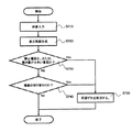
図7は、実施の形態1におけるフレームシンクロ処理のフローチャートである。 FIG. 7 is a flowchart of frame synchronization processing in the first embodiment.
本実施の形態1における映像信号処理方法は、次のような処理の流れとなる。 The video signal processing method according to the first embodiment has the following processing flow.
まず、複数の映像の映像信号を入力する(S710)。 First, a plurality of video signals are input (S710).
続いて、入力した複数の映像を同時に表示するための表示同期信号を発生させる。これは、複数の映像信号のV同期のうち、いずれか1つのV同期を選択し、表示同期信号とする(S720)。 Subsequently, a display synchronization signal for simultaneously displaying a plurality of input images is generated. This selects any one of the V synchronizations of the plurality of video signals and sets it as a display synchronization signal (S720).
次に、複数の映像信号のうち表示用同期信号と同期ずれが発生する映像信号に対して、同期ずれ解消の期間を判定する。まず、同期ずれが発生する映像信号について、その映像が静止場面であるのか、または、映像信号のフレームの動き量が所定の大きさ以上の場面であるのか否か判断する。静止場面である場合や、動き量が大きい場合には(S730でYes)、同期ずれを解消する(S750)。 Next, a period for eliminating the synchronization deviation is determined for a video signal that is out of synchronization with the display synchronization signal among the plurality of video signals. First, it is determined whether or not the video signal in which the synchronization shift occurs is a still scene or whether the motion amount of the frame of the video signal is a predetermined size or more. If it is a still scene or if the amount of motion is large (Yes in S730), the synchronization error is eliminated (S750).
静止場面ではないもので、動き量が大きくない場合には(S730でNo)、同期ずれが発生する映像信号について、その映像の場面が変化する場面であるか否かを判断する。映像の場面が変化する場面である場合には(S740でYes)、同期ずれを解消する(S750)。 If it is not a still scene and the amount of motion is not large (No in S730), it is determined whether or not the video signal is a scene where the video scene changes with respect to the video signal in which synchronization loss occurs. If the video scene changes (Yes in S740), the synchronization error is eliminated (S750).
上記のS730、S740のいずれの判断においても、該当しない場合(Noである場合)には、同期ずれの解消をしない。 If none of the above determinations in S730 and S740 is applicable (No), the synchronization error is not eliminated.
同期ずれの解消は、同期ずれを発生する映像信号のV同期に対して、表示同期信号が遅れている(表示同期信号の間隔が長い)場合には、同じ時刻のフレームを繰り返して表示する。表示同期信号の方が進んでいる場合(表示同期信号の間隔が短い)場合には、フレームを間引いて表示する。 To eliminate the synchronization error, when the display synchronization signal is delayed (the interval between the display synchronization signals is long) with respect to the V synchronization of the video signal causing the synchronization error, the frames at the same time are repeatedly displayed. When the display synchronization signal is advanced (when the interval of the display synchronization signal is short), the frame is thinned and displayed.
(実施の形態2)
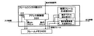
図5は、本発明の実施の形態2におけるフレームシンクロ部301の構成図である。
(Embodiment 2)
FIG. 5 is a configuration diagram of the frame synchronization unit 301 according to the second embodiment of the present invention.
フレームシンクロ部301は、アドレス制御部320、補間フレーム生成部360から構成されている。補間フレーム生成部360は、動きベクトル検出部361と、動き補償画像生成部362とから構成されている。
The frame synchronizer 301 includes an
補間フレーム生成部360は、時間的に連続する複数のフレームから中間位相の補間フレームを生成する。動きベクトル検出部361は、時間的に連続する複数のフレームから動きベクトルを検出する。動き補償画像生成部362は、検出された動きベクトルから動き補償による補間画像を生成する。 The interpolation frame generation unit 360 generates an intermediate phase interpolation frame from a plurality of temporally continuous frames. The motion vector detection unit 361 detects a motion vector from a plurality of temporally continuous frames. The motion compensated image generation unit 362 generates an interpolation image by motion compensation from the detected motion vector.
次に、上述した構成について具体例を挙げその動作を説明する。ここで、アドレス制御部320の動作は、実施の形態1で説明した通りである。
Next, the operation of the above-described configuration will be described with a specific example. Here, the operation of the
本実施の形態2では、フレームリピート、または、フレームスキップする前後のフレームを、フレーム間隔が時間的にほぼ均等となるような時間に相当する補間フレームと置き換えることを特徴とする。補間フレーム生成部360において、この補間フレームを生成する。 The second embodiment is characterized in that the frame before and after frame repeat or frame skip is replaced with an interpolated frame corresponding to a time such that the frame intervals are substantially equal in time. The interpolation frame generation unit 360 generates this interpolation frame.
図6は、補間フレーム生成部360におけるフレームの置き換えを示した説明図である。図6において、フレーム位相差を1としており、表示同期信号の周期がやや早い場合を示す(リピートの場合を例示しているが、スキップについても同様)。 FIG. 6 is an explanatory diagram showing frame replacement in the interpolated frame generation unit 360. In FIG. 6, the case where the frame phase difference is 1 and the period of the display synchronization signal is slightly early is shown (the case of repeat is illustrated, but the same applies to skip).
入力された映像信号の書き込みアドレスとして1、2、3、…、7と書き込まれている。入力された映像信号をフレーム「3」に書き込みしている期間中に、表示同期信号が2回発生している。位相差「1」で読み込みアドレスを設定した場合には、読み込みアドレスとして0、1、2、2、3、4…となり、フレーム「2」が繰り返して読み出される。補間フレーム生成部360では、この1、2、2、3、4の間のフレームを時間的に均等になるように補間フレームを生成する。1フレームから4フレーム目までを、5枚のフレームを生成する。この5枚の補間フレームは、両側の1フレーム、4フレームはそのままで間をほぼ均等として、1、1.8、2.5、3.2、4フレームと生成する。小数は時間的な位相重心を表している。補間フレームを生成することを表す。つまり、1.8のフレームならば、フレーム1とフレーム2とを、1:4の比率の動き補償で線形補間する。また、2.5のフレームならば、フレーム2とフレーム3とを、1:1で線形補間する。
.., 7 are written as write addresses of the input video signal. The display synchronization signal is generated twice during the period in which the input video signal is written in the frame “3”. When the read address is set with the phase difference “1”, the read addresses are 0, 1, 2, 2, 3, 4,... And the frame “2” is read repeatedly. The interpolation frame generation unit 360 generates an interpolation frame so that the frames between 1, 2, 2, 3, and 4 are temporally equal. Five frames are generated from the first frame to the fourth frame. These five interpolated frames are generated as 1, 1.8, 2.5, 3.2, 4 and 4 frames, with 1 frame and 4 frames on both sides being left as they are, and the interval between them being almost equal. The decimal represents the temporal phase centroid. Indicates that an interpolation frame is generated. That is, if the frame is 1.8, the
線形補間には、動きベクトル検出部361にて2つのフレーム間の動きベクトルを検出し、検出した動きベクトルを先の比率で補間した動き補償画像を動き補償画像生成部362で生成する。 In linear interpolation, a motion vector detection unit 361 detects a motion vector between two frames, and a motion compensation image generation unit 362 generates a motion compensated image obtained by interpolating the detected motion vector at the previous ratio.
動きベクトル検出部361は、検出対象となる入力映像のフレームをいくつかに分割し、この分割した小領域の各々の動きベクトルを、入力映像の前後(時間的には過去と未来となる)フレームを参照することにより推定する。分割した小領域のそれぞれに相当する箇所を、入力映像の前後のフレームである参照フレーム内から探索する。この際に、例えば、輝度差分の総和が最小となる箇所を求める手法がある。 The motion vector detection unit 361 divides an input video frame to be detected into several frames, and each motion vector of the divided small area is a frame before and after the input video (in the past and the future in time). Is estimated by referring to. A portion corresponding to each of the divided small regions is searched from within a reference frame that is a frame before and after the input video. At this time, for example, there is a method for obtaining a portion where the sum of luminance differences is minimum.
動き補償画像生成部362は、入力映像の連続する2つのフレームからその中間(所定位相)に相当するフレームを生成する。例えば、中間フレームの各画素は、その画素が有する動きベクトルが指す、前後2フレームの画素を、位相に応じた比率で混合することにより中間フレームとして生成する。 The motion compensated image generation unit 362 generates a frame corresponding to the middle (predetermined phase) from two consecutive frames of the input video. For example, each pixel of the intermediate frame is generated as an intermediate frame by mixing the pixels of two frames before and after the motion vector of the pixel at a ratio according to the phase.
このように、読み出しアドレスで指定されたフレームをそのまま出力映像として出力するのではなく、間を補間したフレームを補間フレーム生成部360で生成することで、フレームリピートによる繰り返したフレームが表示されるよりも、フレームの時間的な連続性が改善されるため、ユーザにとってジャダーが軽減される。 In this way, the frame specified by the read address is not output as an output video as it is, but the interpolated frame is generated by the interpolated frame generation unit 360, so that a repeated frame by frame repeat is displayed. However, since the temporal continuity of frames is improved, judder is reduced for the user.
図8は、本実施の形態2における同期ずれの解消を表すフローチャートである。 FIG. 8 is a flowchart showing the elimination of the synchronization error in the second embodiment.
入力された映像信号が、同期ずれを発生する可能性があると判断された際に、同期ずれを解消する期間を決定し、その期間では時刻が均等になるように補間時刻相当のフレームを決定する(S810)。 When it is determined that there is a possibility that the input video signal may be out of sync, determine the period to eliminate the out of sync and determine the frame equivalent to the interpolation time so that the time is equal during that period (S810).
続いて、決定された補間時刻の前後となる時刻に相当する、入力映像信号に映像のフレームを補間して、補間フレームを生成(S820)する。 Subsequently, the video frame is interpolated into the input video signal corresponding to the time before and after the determined interpolation time to generate an interpolation frame (S820).
本実施の形態2では、フレームリピートが発生する際に、補間フレームを生成することについて説明したが、フレームスキップが発生する際にも、同様に補間フレームを生成することで、フレームの時間的な連続性を改善することができる。 In the second embodiment, the generation of the interpolated frame when the frame repeat occurs has been described. However, when the frame skip occurs, the interpolated frame is generated in the same manner, so that the time of the frame is increased. Continuity can be improved.
以上のように、本発明によればフレームシンクロ処理によるジャダーを軽減し、スムースで高品位な映像表示が可能となる。よって本発明は、複数の映像を多画面表示するような映像信号処理装置および方法等に有用である。 As described above, according to the present invention, judder due to frame synchronization processing is reduced, and a smooth and high-quality video display can be achieved. Therefore, the present invention is useful for a video signal processing apparatus and method for displaying a plurality of videos on a multi-screen.
100 映像入力部
200 表示同期生成部
300 フレームシンクロ部
301 フレームシンクロ部
310 シンクロタイミング検出部
311 動き検出部
312 シーンチェンジ検出部
320 アドレス制御部
360 補間フレーム生成部
361 動きベクトル検出部
362 動き補償画像生成部
400 フレームメモリ
500 多画面合成部
600 映像表示部
DESCRIPTION OF
Claims (7)
複数の前記映像の映像信号を入力する映像入力部と、
フリーラン垂直同期信号、または、複数の前記映像信号のうちの一つの映像信号における垂直同期信号を基準として、前記表示用画面を表示するための同期信号である表示同期信号を生成する表示同期生成部と、
前記映像入力部から入力した複数の前記映像信号を、前記表示同期信号に同期して出力するフレームシンクロ部と、
前記フレームシンクロ部から出力した複数の映像信号を合成して前記表示用画面として生成する多画面合成部とを備え、
前記フレームシンクロ部は、複数の前記映像信号のうち、前記表示同期信号とは同期ずれが発生する映像信号に対して、同期ずれを解消する適当な期間を判定するシンクロタイミング検出部を備え、
前記シンクロタイミング検出部で判定した期間において、前記表示同期信号とは同期ずれが発生する映像信号に対して、同じ時刻のフレームを繰り返して出力するか、または、フレームを間引いて出力することで同期ずれを解消することを特徴とする映像信号処理装置。 A video signal processing apparatus for generating a display screen for simultaneously displaying a plurality of videos on a screen,
A video input unit for inputting a plurality of video signals of the video;
Display synchronization generation for generating a display synchronization signal, which is a synchronization signal for displaying the display screen, based on a free-running vertical synchronization signal or a vertical synchronization signal in one of the plurality of video signals. And
A plurality of the video signals input from the video input unit, a frame synchronization unit that outputs in synchronization with the display synchronization signal;
A multi-screen synthesis unit that synthesizes a plurality of video signals output from the frame synchronization unit and generates the display screen;
The frame synchronization unit includes a synchronization timing detection unit that determines an appropriate period for eliminating the synchronization shift with respect to a video signal in which a synchronization shift occurs with the display synchronization signal among the plurality of video signals.
In the period determined by the synchro timing detection unit, the video signal that is out of synchronization with the display synchronization signal is output by repeating a frame at the same time or by thinning out and outputting the frame. A video signal processing apparatus characterized by eliminating the deviation.
前記映像信号に含まれる映像の動き量を検出する動き検出部と、
前記映像信号の含まれる映像の場面の切り替わりを検出するシーンチェンジ検出部とを備え、
映像の動き量がないと判断できる場面、映像の動き量が所定の大きさ以上となっている場面、または映像の場面の切り替わりを検出し、前記同期ずれを解消する適当な期間として判定する
ことを特徴とする請求項1記載の映像信号処理装置。 The synchronization timing detection unit
A motion detector that detects the amount of motion of the video included in the video signal;
A scene change detection unit for detecting a change of a scene of a video including the video signal;
Detecting a scene where it can be determined that there is no video motion amount, a scene where the video motion amount is greater than or equal to a predetermined amount, or a change in the video scene, and determining that it is an appropriate period to eliminate the synchronization gap The video signal processing apparatus according to claim 1.
複数の前記映像の映像信号を入力する映像入力部と、
フリーラン垂直同期信号、または、複数の前記映像信号のうちの一つの映像信号における垂直同期信号を基準として、前記表示用画面を表示するための同期信号である表示同期信号を生成する表示同期生成部と、
前記映像入力部から入力した複数の前記映像信号を、前記表示同期信号に同期して出力するフレームシンクロ部と、
前記フレームシンクロ部から出力した複数の映像信号を合成して前記表示用画面として生成する多画面合成部とを備え、
前記フレームシンクロ部は、複数の前記映像信号のうち、前記表示同期信号とは同期ずれが発生する映像信号に対して、時間的に連続する複数のフレームから中間位相の補間フレームを生成する補間フレーム生成部とを備え、
前記表示同期信号とは同期ずれが発生する映像信号に対して、同期ずれを解消する期間においては、当該映像信号に代わり前記補間フレーム生成部で生成した中間フレームに置き換えることで同期ずれを解消する
ことを特徴とする映像信号処理装置。 A video signal processing apparatus for generating a display screen for simultaneously displaying a plurality of videos on a screen,
A video input unit for inputting a plurality of video signals of the video;
Display synchronization generation for generating a display synchronization signal, which is a synchronization signal for displaying the display screen, based on a free-running vertical synchronization signal or a vertical synchronization signal in one of the plurality of video signals. And
A plurality of the video signals input from the video input unit, a frame synchronization unit that outputs in synchronization with the display synchronization signal;
A multi-screen synthesis unit that synthesizes a plurality of video signals output from the frame synchronization unit and generates the display screen;
The frame synchronization unit generates an interpolation frame of an intermediate phase from a plurality of temporally continuous frames for a video signal that is out of synchronization with the display synchronization signal among the plurality of video signals. A generator,
For a video signal in which a synchronization error occurs with respect to the display synchronization signal, the synchronization error is eliminated by replacing the video signal with an intermediate frame generated by the interpolation frame generation unit in a period for eliminating the synchronization error. A video signal processing apparatus.
時間的に連続する複数のフレームから動きベクトルを検出する動きベクトル検出部と、
前記動きベクトル検出部で検出した動きベクトルから、動き補償による補間画像を生成する動き補償画像生成部とを備え、
前記補間画像を前記中間位相の補間フレームとして生成する
ことを特徴とする請求項3記載の映像信号処理装置。 The interpolation frame generation unit
A motion vector detector that detects a motion vector from a plurality of temporally continuous frames;
A motion compensation image generation unit that generates an interpolation image by motion compensation from the motion vector detected by the motion vector detection unit;
4. The video signal processing apparatus according to claim 3, wherein the interpolated image is generated as an interpolated frame of the intermediate phase.
複数の前記映像の映像信号を入力する映像入力ステップと、
フリーラン垂直同期信号、または、複数の前記映像信号のうちの一つの映像信号における垂直同期信号を基準として、前記表示用画面を表示するための同期信号である表示同期信号を生成する表示同期生成ステップと、
入力した複数の前記映像信号を、前記表示同期信号に同期して出力するフレームシンクロステップと、
前記フレームシンクロステップにより出力した複数の映像信号を合成して前記表示用画面として生成する多画面合成ステップとを含み、
前記フレームシンクロステップは、複数の前記映像信号のうち、前記表示同期信号とは同期ずれが発生する映像信号に対して、同期ずれを解消する適当な期間を判定するシンクロタイミング検出ステップを含み、
前記シンクロタイミング検出ステップで判定した期間において、前記表示同期信号とは同期ずれが発生する映像信号に対して、同じ時刻のフレームを繰り返して出力するか、または、フレームを間引いて出力することで同期ずれを解消する
ことを特徴とする映像信号処理方法。 A video signal processing method for generating a display screen for simultaneously displaying a plurality of videos on a screen,
A video input step of inputting a plurality of video signals of the video;
Display synchronization generation for generating a display synchronization signal, which is a synchronization signal for displaying the display screen, based on a free-running vertical synchronization signal or a vertical synchronization signal in one of the plurality of video signals. Steps,
A frame synchronization step for outputting the plurality of input video signals in synchronization with the display synchronization signal;
A multi-screen synthesis step of generating a plurality of video signals output by the frame synchronization step to generate the display screen,
The frame synchronization step includes a synchronization timing detection step of determining an appropriate period for eliminating the synchronization shift with respect to the video signal in which a synchronization shift occurs with the display synchronization signal among the plurality of video signals,
In the period determined in the sync timing detection step, for the video signal that is out of synchronization with the display synchronization signal, the video signal having the same time is repeatedly output or the frame is thinned and output. A video signal processing method characterized by eliminating the deviation.
前記映像信号に含まれる映像の動き量を検出する動き検出ステップと、
前記映像信号の含まれる映像の場面の切り替わりを検出するシーンチェンジ検出ステップとを備え、
映像の動き量がないと判断できる場面、映像の動き量が所定の大きさ以上となっている場面、または映像の場面の切り替わりを検出し、前記同期ずれを解消する適当な期間として判定する
ことを特徴とする請求項5記載の映像信号処理方法。 The synchronization timing detection step includes
A motion detection step of detecting a motion amount of a video included in the video signal;
A scene change detection step for detecting a change of a scene of a video including the video signal,
Detecting a scene where it can be determined that there is no video motion amount, a scene where the video motion amount is greater than or equal to a predetermined amount, or a change in the video scene, and determining that it is an appropriate period to eliminate the synchronization gap The video signal processing method according to claim 5.
複数の前記映像の映像信号を入力する映像入力ステップと、
フリーラン垂直同期信号、または、複数の前記映像信号のうちの一つの映像信号における垂直同期信号を基準として、前記表示用画面を表示するための同期信号である表示同期信号を生成する表示同期生成ステップと、
入力した複数の前記映像信号を、前記表示同期信号に同期して出力するフレームシンクロステップと、
前記フレームシンクロステップにより出力した複数の映像信号を合成して前記表示用画面として生成する多画面合成ステップとを含み、
前記フレームシンクロステップは、複数の前記映像信号のうち、前記表示同期信号とは同期ずれが発生する映像信号に対して、時間的に連続する複数のフレームから中間位相の補間フレームを生成する補間フレーム生成ステップを備え、
前記表示同期信号とは同期ずれが発生する映像信号に対して、同期ずれを解消する期間においては、当該映像信号に代わり前記補間フレーム生成部で生成した中間フレームに置き換えることで同期ずれを解消する
ことを特徴とする映像信号処理方法。 A video signal processing method for generating a display screen for simultaneously displaying a plurality of videos on a screen,
A video input step of inputting a plurality of video signals of the video;
Display synchronization generation for generating a display synchronization signal, which is a synchronization signal for displaying the display screen, based on a free-running vertical synchronization signal or a vertical synchronization signal in one of the plurality of video signals. Steps,
A frame synchronization step for outputting the plurality of input video signals in synchronization with the display synchronization signal;
A multi-screen synthesis step of generating a plurality of video signals output by the frame synchronization step to generate the display screen,
The frame synchronization step generates an interpolated frame of an intermediate phase from a plurality of temporally continuous frames for a video signal that is out of synchronization with the display synchronization signal among the plurality of video signals. With a generation step,
For a video signal in which a synchronization error occurs with respect to the display synchronization signal, the synchronization error is eliminated by replacing the video signal with an intermediate frame generated by the interpolation frame generation unit in a period for eliminating the synchronization error. And a video signal processing method.
Priority Applications (2)
| Application Number | Priority Date | Filing Date | Title |
|---|---|---|---|
| JP2011026831A JP2012169727A (en) | 2011-02-10 | 2011-02-10 | Image signal processor and image signal processing method |
| PCT/JP2011/007062 WO2012107985A1 (en) | 2011-02-10 | 2011-12-19 | Image signal processing device and image signal processing method |
Applications Claiming Priority (1)
| Application Number | Priority Date | Filing Date | Title |
|---|---|---|---|
| JP2011026831A JP2012169727A (en) | 2011-02-10 | 2011-02-10 | Image signal processor and image signal processing method |
Publications (1)
| Publication Number | Publication Date |
|---|---|
| JP2012169727A true JP2012169727A (en) | 2012-09-06 |
Family
ID=46638228
Family Applications (1)
| Application Number | Title | Priority Date | Filing Date |
|---|---|---|---|
| JP2011026831A Withdrawn JP2012169727A (en) | 2011-02-10 | 2011-02-10 | Image signal processor and image signal processing method |
Country Status (2)
| Country | Link |
|---|---|
| JP (1) | JP2012169727A (en) |
| WO (1) | WO2012107985A1 (en) |
Cited By (6)
| Publication number | Priority date | Publication date | Assignee | Title |
|---|---|---|---|---|
| KR101553846B1 (en) | 2014-12-16 | 2015-09-17 | 연세대학교 산학협력단 | Apparatus and Method of frame synchronization for video stitching |
| WO2016017266A1 (en) * | 2014-07-29 | 2016-02-04 | 三菱電機株式会社 | Video information playback device and playback method |
| WO2016195409A1 (en) * | 2015-06-03 | 2016-12-08 | 어드밴인터내셔널코프 | Vertical synchronization delay calculating method and apparatus |
| GB2547438A (en) * | 2016-02-17 | 2017-08-23 | Insync Tech Ltd | Method and apparatus for generating a video field/frame |
| JPWO2023017577A1 (en) * | 2021-08-11 | 2023-02-16 | ||
| US12431109B2 (en) | 2021-10-19 | 2025-09-30 | Samsung Electronics Co., Ltd. | Display device and control method for outputting image signal including interpolation frame |
Families Citing this family (1)
| Publication number | Priority date | Publication date | Assignee | Title |
|---|---|---|---|---|
| CN113067960B (en) * | 2021-03-16 | 2022-08-12 | 合肥合芯微电子科技有限公司 | Image interpolation method, device and storage medium |
Family Cites Families (6)
| Publication number | Priority date | Publication date | Assignee | Title |
|---|---|---|---|---|
| JP2004048530A (en) * | 2002-07-15 | 2004-02-12 | Matsushita Electric Ind Co Ltd | Frame rate conversion device and conversion information multiplexing device |
| JP4047316B2 (en) * | 2003-09-25 | 2008-02-13 | キヤノン株式会社 | Frame rate conversion device, overtaking prediction method used therefor, display control device, and video reception display device |
| JP2005341132A (en) * | 2004-05-26 | 2005-12-08 | Toshiba Corp | Video data processing apparatus and processing method |
| JP2006050230A (en) * | 2004-08-04 | 2006-02-16 | Hitachi Ltd | Frame rate conversion method, conversion device, image signal recording device, and playback device |
| JP5174329B2 (en) * | 2006-05-23 | 2013-04-03 | 株式会社日立製作所 | Image processing apparatus and image display apparatus |
| JP4513819B2 (en) * | 2007-03-19 | 2010-07-28 | 株式会社日立製作所 | Video conversion device, video display device, and video conversion method |
-
2011
- 2011-02-10 JP JP2011026831A patent/JP2012169727A/en not_active Withdrawn
- 2011-12-19 WO PCT/JP2011/007062 patent/WO2012107985A1/en not_active Ceased
Cited By (12)
| Publication number | Priority date | Publication date | Assignee | Title |
|---|---|---|---|---|
| WO2016017266A1 (en) * | 2014-07-29 | 2016-02-04 | 三菱電機株式会社 | Video information playback device and playback method |
| JPWO2016017266A1 (en) * | 2014-07-29 | 2017-04-27 | 三菱電機株式会社 | Video information reproducing apparatus and reproducing method |
| KR101553846B1 (en) | 2014-12-16 | 2015-09-17 | 연세대학교 산학협력단 | Apparatus and Method of frame synchronization for video stitching |
| WO2016195409A1 (en) * | 2015-06-03 | 2016-12-08 | 어드밴인터내셔널코프 | Vertical synchronization delay calculating method and apparatus |
| KR20160142924A (en) * | 2015-06-03 | 2016-12-14 | 어드밴인터내셔널코프 | Method and apparatus of V-Sync Delay Calculation |
| KR101687104B1 (en) | 2015-06-03 | 2016-12-16 | 어드밴인터내셔널코프 | Method and apparatus of V-Sync Delay Calculation |
| GB2547438A (en) * | 2016-02-17 | 2017-08-23 | Insync Tech Ltd | Method and apparatus for generating a video field/frame |
| GB2547438B (en) * | 2016-02-17 | 2019-07-03 | Insync Tech Limited | Method and apparatus for generating a video field/frame |
| JPWO2023017577A1 (en) * | 2021-08-11 | 2023-02-16 | ||
| WO2023017577A1 (en) * | 2021-08-11 | 2023-02-16 | 日本電信電話株式会社 | Apparatus, method, and program for combining video signals |
| JP7658442B2 (en) | 2021-08-11 | 2025-04-08 | 日本電信電話株式会社 | Apparatus, method and program for synthesizing video signals |
| US12431109B2 (en) | 2021-10-19 | 2025-09-30 | Samsung Electronics Co., Ltd. | Display device and control method for outputting image signal including interpolation frame |
Also Published As
| Publication number | Publication date |
|---|---|
| WO2012107985A1 (en) | 2012-08-16 |
Similar Documents
| Publication | Publication Date | Title |
|---|---|---|
| EP0913053B1 (en) | Synchronization of multiple video and graphic sources with a display using a slow pll approach | |
| US7158186B2 (en) | Method and system for changing the frame rate to be optimal for the material being displayed while maintaining a stable image throughout | |
| US8842742B2 (en) | Frame-rate conversion | |
| JP2012169727A (en) | Image signal processor and image signal processing method | |
| US8593575B2 (en) | Video display apparatus for shortened-delay processing of a video signal and video processing method | |
| JP2010041538A (en) | Device and method for processing image signal | |
| US20090196567A1 (en) | Video processing apparatus and controlling method for same | |
| JP4691193B1 (en) | Video display device and video processing method | |
| US8154654B2 (en) | Frame interpolation device, frame interpolation method and image display device | |
| JP2003189257A (en) | Image signal processing apparatus and method | |
| JP2005318610A (en) | Sequence-compatible synchronization signal generator | |
| KR20100040558A (en) | Method for setting frame rate conversion and display apparatus applying the same | |
| US10212316B2 (en) | Video processing apparatus | |
| KR100487396B1 (en) | Digital TV system for supporting of film mode and method for the same | |
| JP4951487B2 (en) | Video processing apparatus and video display apparatus using the same | |
| JP7630993B2 (en) | Display device, signal processing device, and signal processing method | |
| JP2004194311A (en) | Video playback device and video playback method | |
| US20110298977A1 (en) | Video processing device | |
| JP2012182691A (en) | Image conversion device | |
| JP5259867B2 (en) | Video display device and video processing method | |
| US8730398B2 (en) | Video output apparatus and control method therefor, and non-transitory recording (storing) medium that records program | |
| JP2001309202A (en) | Frame synchronizer | |
| JP2014216740A (en) | Video signal processing device and method, program and recording medium | |
| JP5207866B2 (en) | Video signal processing method and video signal processing apparatus | |
| JP5534948B2 (en) | Image processing apparatus and control method thereof |
Legal Events
| Date | Code | Title | Description |
|---|---|---|---|
| A300 | Application deemed to be withdrawn because no request for examination was validly filed |
Free format text: JAPANESE INTERMEDIATE CODE: A300 Effective date: 20140513 |