JP2012169262A - Depurant container device for fuel cell system and fuel cell system - Google Patents
Depurant container device for fuel cell system and fuel cell system Download PDFInfo
- Publication number
- JP2012169262A JP2012169262A JP2012004261A JP2012004261A JP2012169262A JP 2012169262 A JP2012169262 A JP 2012169262A JP 2012004261 A JP2012004261 A JP 2012004261A JP 2012004261 A JP2012004261 A JP 2012004261A JP 2012169262 A JP2012169262 A JP 2012169262A
- Authority
- JP
- Japan
- Prior art keywords
- flow path
- fuel cell
- forming member
- fluid
- fuel
- Prior art date
- Legal status (The legal status is an assumption and is not a legal conclusion. Google has not performed a legal analysis and makes no representation as to the accuracy of the status listed.)
- Granted
Links
Images


Classifications
-
- H—ELECTRICITY
- H01—ELECTRIC ELEMENTS
- H01M—PROCESSES OR MEANS, e.g. BATTERIES, FOR THE DIRECT CONVERSION OF CHEMICAL ENERGY INTO ELECTRICAL ENERGY
- H01M8/00—Fuel cells; Manufacture thereof
- H01M8/06—Combination of fuel cells with means for production of reactants or for treatment of residues
- H01M8/0662—Treatment of gaseous reactants or gaseous residues, e.g. cleaning
- H01M8/0675—Removal of sulfur
-
- Y—GENERAL TAGGING OF NEW TECHNOLOGICAL DEVELOPMENTS; GENERAL TAGGING OF CROSS-SECTIONAL TECHNOLOGIES SPANNING OVER SEVERAL SECTIONS OF THE IPC; TECHNICAL SUBJECTS COVERED BY FORMER USPC CROSS-REFERENCE ART COLLECTIONS [XRACs] AND DIGESTS
- Y02—TECHNOLOGIES OR APPLICATIONS FOR MITIGATION OR ADAPTATION AGAINST CLIMATE CHANGE
- Y02E—REDUCTION OF GREENHOUSE GAS [GHG] EMISSIONS, RELATED TO ENERGY GENERATION, TRANSMISSION OR DISTRIBUTION
- Y02E60/00—Enabling technologies; Technologies with a potential or indirect contribution to GHG emissions mitigation
- Y02E60/30—Hydrogen technology
- Y02E60/50—Fuel cells
-
- Y—GENERAL TAGGING OF NEW TECHNOLOGICAL DEVELOPMENTS; GENERAL TAGGING OF CROSS-SECTIONAL TECHNOLOGIES SPANNING OVER SEVERAL SECTIONS OF THE IPC; TECHNICAL SUBJECTS COVERED BY FORMER USPC CROSS-REFERENCE ART COLLECTIONS [XRACs] AND DIGESTS
- Y02—TECHNOLOGIES OR APPLICATIONS FOR MITIGATION OR ADAPTATION AGAINST CLIMATE CHANGE
- Y02P—CLIMATE CHANGE MITIGATION TECHNOLOGIES IN THE PRODUCTION OR PROCESSING OF GOODS
- Y02P70/00—Climate change mitigation technologies in the production process for final industrial or consumer products
- Y02P70/50—Manufacturing or production processes characterised by the final manufactured product
Abstract
Description
本発明は、燃料電池システムで用いられる燃料、改質用水蒸気となる水等の流体を浄化させる燃料電池システム用浄化剤収容装置および燃料電池システムに関する。 The present invention relates to a fuel cell system purifier containing device and a fuel cell system for purifying fluids such as fuel used in a fuel cell system and water used as reforming water vapor.
燃料電池システムで用いられる燃料に含まれる付臭剤を除去する脱硫器を例にとって、背景技術を説明する。脱硫剤を収容する脱硫器の設計にあたり、限られた脱硫器のスペースで、コストを抑えつつ、脱硫剤を有効に利用することは重要な課題である。そのため脱硫器となる容器の内部にUターン部を形成する中板部材を設置し、ガスの流れを整流することが、しばしば試みられる。特許文献1、特許文献2、特許文献3(図3)では、脱硫器となる容器の内部にUターン用の中板部材が設けられ、ガス状の燃料が容器内で偏流することを防止すると共に意図的な流れを構成して、脱硫剤の有効活用を試みている。
The background art will be described by taking as an example a desulfurizer that removes an odorant contained in fuel used in a fuel cell system. In designing a desulfurizer that accommodates a desulfurizing agent, it is an important issue to effectively use the desulfurizing agent in a limited desulfurizer space while suppressing costs. Therefore, it is often attempted to rectify the flow of gas by installing an intermediate plate member that forms a U-turn portion inside a vessel that serves as a desulfurizer. In
上記した特許文献1〜3ともに、脱硫器の製造は必ずしも容易ではない。特に、燃料をUターンさせるため、中板部材を接合部でシールさせつつ容器の内部に固定させる構造が必要である。しかしこの製造過程は必ずしも容易ではない。製造が容易でないため、製造過程において、高いシール性をもつ良好な接合部(例えば溶接部やろう付け部)が得られないおそれがある。この場合、必ずしも良好ではない接合部をガス状の燃料がショートカット的に透過し、脱硫が充分になされないまま、出口ポートから改質器に導出されるおそれがあり、好ましくない。
In all of
本発明は上記した実情に鑑みてなされたものであり、製造が容易であり、高いシール性をもつ良好な接合部を形成させるのに有利な燃料電池システム用浄化剤収容装置、および、その浄化剤収容装置を備える燃料電池システムを提供することを課題とする。 The present invention has been made in view of the above-described circumstances, and is easy to manufacture and is advantageous for forming a good joint having a high sealing property, and a purification agent storage device for a fuel cell system, and purification thereof It is an object of the present invention to provide a fuel cell system including an agent storage device.
(1)本発明に係る燃料電池システム用浄化剤収容装置は、燃料電池システムで用いられるガス状または液相状の浄化用の流体を入口ポートから導入してUターンさせた後に出口ポートから外部に導出させる燃料電池システム用浄化剤収容装置であって、(i)入口ポートと出口ポートとの間において流体をUターンさせるためのUターン開口と互いに背向する第1表面および第2表面とをもつ中板部材と、(ii)流体が流れる第1流路を形成する第1流路形成部材と、(iii)Uターン開口を介して第1流路に連通する第2流路を形成する第2流路形成部材とを具備しており、(iv)第1流路形成部材は中板部材の第1表面側に接合部で接合され、第2流路形成部材は中板部材の第2表面側に接合部で接合されてシールされている。 (1) A purifier containing device for a fuel cell system according to the present invention introduces a gas or liquid phase purification fluid used in a fuel cell system from an inlet port and makes a U-turn, and then externally from the outlet port. And (i) a U-turn opening for U-turning fluid between an inlet port and an outlet port, and a first surface and a second surface facing each other. (Ii) a first flow path forming member that forms a first flow path through which a fluid flows, and (iii) a second flow path that communicates with the first flow path through a U-turn opening. (Iv) the first flow path forming member is joined to the first surface side of the middle plate member at the joint portion, and the second flow path forming member is made of the middle plate member. It is joined and sealed to the second surface side by a joint portion.
浄化剤収容装置の用途としては、燃料の付臭剤を除去させる脱硫器、または、改質用の水を精製させる水精製器が例示される。脱硫器に適用される場合には、流体は付臭剤を含む燃料であり、浄化剤は脱硫機能をもつゼオライト、活性炭が例示される。水精製器に適用される場合には、流体は、燃料を水蒸気改質させる水蒸気となる水であり、浄化剤はイオン交換樹脂等の水精製剤が例示される。製造過程にあたり、第1流路をもつ第1流路形成部材は中板部材の第1表面側にあてがわれて接合部で接合されてシールされる。第2流路をもつ第2流路形成部材は、中板部材の第2表面側にあてがわれて接合部で接合されてシールされる。このため、高いシール性を確保させつつ、組み付けを容易にできる。組み付けが容易であるため、接合部のシール不良も抑えられる。よって高いシール性をもつ脱硫器や水精製器等の浄化剤収容装置が得られる。 Examples of the use of the purifying agent storage device include a desulfurizer that removes the odorant of fuel or a water purifier that purifies water for reforming. When applied to a desulfurizer, the fluid is a fuel containing an odorant, and the purification agent is exemplified by zeolite or activated carbon having a desulfurization function. When applied to a water purifier, the fluid is water that becomes steam for reforming the fuel by steam, and the purifier is exemplified by a water purifier such as an ion exchange resin. In the manufacturing process, the first flow path forming member having the first flow path is applied to the first surface side of the intermediate plate member and joined and sealed at the joint portion. The second flow path forming member having the second flow path is applied to the second surface side of the intermediate plate member and joined and sealed at the joint portion. For this reason, assembly can be facilitated while ensuring high sealing performance. Since it is easy to assemble, poor sealing at the joint can be suppressed. Therefore, it is possible to obtain a cleaning agent storage device such as a desulfurizer and a water purifier having high sealing performance.
(2)本発明に係る燃料電池システムは、アノード流体およびカソード流体が供給されて発電する燃料電池と、水蒸気を用いて燃料を改質させてアノード流体を形成する改質部と、アノード流体となる燃料を改質部に供給する燃料通路と、燃料通路に設けられ燃料に含まれる付臭剤を除去して燃料を浄化させる脱硫剤を浄化剤として収容するための脱硫器とを具備しており、脱硫器は、上記した燃料電池システム用浄化剤収容装置で構成されている。 (2) A fuel cell system according to the present invention includes a fuel cell that is supplied with an anode fluid and a cathode fluid to generate power, a reforming unit that reforms fuel using water vapor to form an anode fluid, an anode fluid, A fuel passage for supplying the fuel to the reforming section, and a desulfurizer for containing a desulfurizing agent provided in the fuel passage for removing the odorant contained in the fuel and purifying the fuel as a purifying agent. The desulfurizer is composed of the above-described purifier containing device for a fuel cell system.
燃料通路は、アノード流体となる燃料を改質部に供給する。脱硫器は、燃料通路に設けられており、燃料に含まれる付臭剤を除去して燃料を浄化させる。改質部は、付臭剤を除去した燃料を水蒸気を用いて改質させてアノード流体(一般的には水素含有流体)を形成する。アノード流体はカソード流体と共に燃料電池に供給され、発電運転に使用される。脱硫器の入口ポートから浄化室に流入された流体は、浄化室の浄化剤によって浄化され、その後、脱硫器の出口ポートから下流機器(例えば改質器または燃料電池)に吐出される。このため、脱硫器においては高いシール性を確保させつつ、組み付けを容易にできるようになっている。組み付けが容易であるため、脱硫器の接合部のシール不良も抑えられる。よって、高いシール性をもつ脱硫器が得られる。このため脱硫剤で充分に浄化されなかった燃料が出口ポートからこれの下流機器(例えば改質器または燃料電池)に吐出されることが抑制され、システムの長期にわたる信頼性が高められる。 The fuel passage supplies fuel to be an anode fluid to the reforming unit. The desulfurizer is provided in the fuel passage and purifies the fuel by removing the odorant contained in the fuel. The reforming unit reforms the fuel from which the odorant has been removed using steam to form an anode fluid (generally a hydrogen-containing fluid). The anode fluid is supplied to the fuel cell together with the cathode fluid and used for power generation operation. The fluid flowing into the purification chamber from the inlet port of the desulfurizer is purified by the purification agent in the purification chamber, and then discharged from the outlet port of the desulfurizer to downstream equipment (for example, a reformer or a fuel cell). Therefore, the desulfurizer can be easily assembled while ensuring high sealing performance. Since it is easy to assemble, poor sealing at the joint of the desulfurizer can be suppressed. Therefore, a desulfurizer having high sealing performance can be obtained. For this reason, the fuel that has not been sufficiently purified by the desulfurizing agent is prevented from being discharged from the outlet port to downstream equipment (for example, a reformer or a fuel cell), thereby improving the long-term reliability of the system.
本発明によれば、第1流路を形成する第1流路形成部材は中板部材の第1表面側にあてがわれて接合部で接合されてシールされる。第1流路を形成する第2流路形成部材は中板部材の第2表面側にあてがわれて接合部で接合されてシールされる。このため、第1流路を形成する第1流路形成部材と、第2流路を形成する第2流路形成部材とを中板部材において表裏の関係で容易に接合でき、組付、ひいては製造が容易である。従って、第1流路形成部材および第2流路形成部材を中板部材に接合させている接合部については、良好に形成できる。このため高いシール性をもつ接合部が得られる。この結果、必ずしもシール性が良好ではない接合部を燃料や水等の流体が第1流路と第2流路との間において中板部材を介してショートカット的に透過することが抑制される。よって、燃料や水等の流体を脱硫剤や水精製剤等の浄化剤で充分に浄化させることができる。このため浄化剤で充分に浄化されなかった燃料や水等の流体が出口ポートからこれの下流機器(例えば改質器または燃料電池)に吐出されることが抑制され、システムの長期にわたる信頼性が高められる。 According to the present invention, the first flow path forming member that forms the first flow path is applied to the first surface side of the intermediate plate member and joined and sealed at the joint portion. The second flow path forming member that forms the first flow path is applied to the second surface side of the intermediate plate member and joined and sealed at the joint portion. For this reason, the first flow path forming member that forms the first flow path and the second flow path forming member that forms the second flow path can be easily joined to each other in the front and back relation in the intermediate plate member, Easy to manufacture. Therefore, it is possible to satisfactorily form the joint where the first flow path forming member and the second flow path forming member are joined to the intermediate plate member. For this reason, a joint part with high sealing performance is obtained. As a result, fluid such as fuel or water is prevented from passing through the intermediate plate member between the first flow path and the second flow path as a shortcut through a joint portion that does not necessarily have good sealing performance. Therefore, fluids such as fuel and water can be sufficiently purified with a purifying agent such as a desulfurizing agent or a water purifying agent. For this reason, it is suppressed that fluids such as fuel and water that have not been sufficiently purified by the purifying agent are discharged from the outlet port to downstream equipment (for example, a reformer or a fuel cell), thereby improving the long-term reliability of the system. Enhanced.
好ましい形態によれば、本装置が脱硫器に適用される場合には、流体は付臭剤を含む燃料であり、浄化剤は、燃料に含まれている付臭剤を除去させるゼオライト、活性炭が例示される。好ましい形態によれば、本装置が水精製器に適用される場合には、流体は燃料を改質させる水蒸気となる水であり、浄化剤はイオン交換樹脂等の水精製剤であり、浄化室は、水に含まれている不純物を除去させて純水化を促進させる水精製剤を収容する。 According to a preferred embodiment, when the present apparatus is applied to a desulfurizer, the fluid is a fuel containing an odorant, and the purifier is a zeolite or activated carbon that removes the odorant contained in the fuel. Illustrated. According to a preferred embodiment, when the present apparatus is applied to a water purifier, the fluid is water that becomes water vapor for reforming the fuel, the purifying agent is a water purifying agent such as an ion exchange resin, and the purifying chamber. Contains a water refining agent that removes impurities contained in water and promotes purification.
好ましい形態によれば、入口ポートからUターンするまでに流体が流れる流体流れ方向に対して交差する方向に沿って切断した断面において、第1流路形成部材および前記第2流路形成部材は、コの字形状、V形状またはC形状をなしている。好ましい形態によれば、前記断面において、接合部は外方に露出する。この場合、万一、接合部の接合不良が存在するときには、接合不良が外部から視認されるため、厳しい探傷検査せずとも発見され易い。例えば、接合部を肉眼で検査しても良いし、石鹸水膜等を塗布した状態で流体を流せば、漏れにより石鹸水膜が膨張等変形するため、視認が容易となる。 According to a preferred embodiment, the first flow path forming member and the second flow path forming member in a cross section cut along a direction intersecting a fluid flow direction in which a fluid flows before making a U-turn from the inlet port, It is U-shaped, V-shaped or C-shaped. According to a preferred embodiment, the joint is exposed outward in the cross section. In this case, if there is a bonding failure in the bonding portion, the bonding failure is visually recognized from the outside, so that it is easy to find without performing a strict flaw detection inspection. For example, the joint portion may be inspected with the naked eye, and if a fluid is allowed to flow in a state where a soapy water film or the like is applied, the soapy water film expands or deforms due to leakage, thereby facilitating visual recognition.
好ましい形態によれば、前記断面において、中板部材の側端部は第1流路形成部材および第2流路形成部材から外方に露出する。この場合、接合部を外方に露出させ易い。この場合、万一、接合部の接合不良が存在するときには、前述したように、接合不良が視認されるため、厳しい探傷検査せずとも発見され易い。このためシール管理の信頼性を高めることができる。 According to a preferred embodiment, in the cross section, the side end portion of the intermediate plate member is exposed outward from the first flow path forming member and the second flow path forming member. In this case, it is easy to expose the joint to the outside. In this case, in the unlikely event that there is a bonding failure in the bonding portion, as described above, the bonding failure is visually recognized. For this reason, the reliability of seal management can be improved.
好ましい形態によれば、中板部材、第1流路形成部材および第2流路形成部材の流体流れ方向の一端側に接合され、第1流路および第2流路の長さ方向の一端を閉鎖させる第1閉鎖板が設けられている。更に中板部材、第1流路形成部材および第2流路形成部材の流体流れ方向の他端側に接合され、第1流路および第2流路の長さ方向の他端を閉鎖させる第2閉鎖板が設けられていることが好ましい。好ましい形態によれば、流体を浄化させる浄化剤が第1流路および第2流路に収容されており、第1流路および/または第2流路の余った空間に、流体を通過させる通気穴を有すると共に浄化剤の遊動を抑える押さえ部材が配置されている。浄化剤の揺れ、振動等の遊動が抑制され、浄化剤の損傷および微粉化が抑制される。押さえ部材としては不織布または織布が例示できる。好ましい形態によれば、第1流路は入口ポートに繋がり、第2流路は出口ポートに繋がり、第2流路に配置された押さえ部材の通気穴のサイズは、第1流路に配置された押さえ部材の通気穴のサイズよりも小さい。この場合、出口ポート側の押さえ部材の通気穴のサイズは相対的に小さいため、微粉化した浄化剤が下流側に移動することが抑制され、詰まり現象等の不具合を下流側に与えることが抑制される。入口出口ポート側の押さえ部材の通気穴のサイズは相対的に大きいため、燃料や水等の流体を導入させる抵抗が低減される。 According to a preferred embodiment, the intermediate plate member, the first flow path forming member, and the second flow path forming member are joined to one end side in the fluid flow direction, and one end of the first flow path and the second flow path in the length direction is connected. A first closing plate is provided for closing. Furthermore, the intermediate plate member, the first flow path forming member, and the second flow path forming member are joined to the other end side in the fluid flow direction, and the other end in the length direction of the first flow path and the second flow path is closed. Two closing plates are preferably provided. According to a preferred embodiment, the purifying agent for purifying the fluid is accommodated in the first flow path and the second flow path, and the air is passed through the remaining space of the first flow path and / or the second flow path. A pressing member that has a hole and suppresses the loosening of the purifier is disposed. Swinging and vibration of the cleaning agent are suppressed, and the damage and pulverization of the cleaning agent are suppressed. Non-woven fabric or woven fabric can be exemplified as the pressing member. According to a preferred embodiment, the first flow path is connected to the inlet port, the second flow path is connected to the outlet port, and the size of the vent hole of the pressing member disposed in the second flow path is disposed in the first flow path. It is smaller than the size of the vent hole of the holding member. In this case, since the size of the vent hole of the pressing member on the outlet port side is relatively small, movement of the pulverized purification agent to the downstream side is suppressed, and the occurrence of problems such as clogging phenomenon is suppressed to the downstream side. Is done. Since the size of the vent hole of the pressing member on the inlet / outlet port side is relatively large, the resistance to introduce a fluid such as fuel or water is reduced.
(実施形態1)
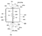
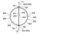
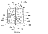
図1〜図5は実施形態1の概念を示す。図1は、燃料電池システムで用いられる脱硫器(燃料電池システム用浄化剤収容装置)を示す。図1に示すように、脱硫器は、燃料電池システムで用いられる浄化が必要なガス状の流体燃料を、入口ポート601から矢印X1方向に第1流路305に導入し、矢印X2方向に流し、更に矢印X3方向にUターンさせ、更に第2流路405を矢印X4方向に流し、出口ポート602から矢印X5方向に向けて外部に導出させる。図1は、入口ポート601からUターンするまでに流体が流れる流れ方向(矢印X1,X2方向)に沿って切断した断面を示す。図2は、入口ポート601からUターンするまでに燃料が流れる流れ方向(矢印X1,X2方向)に対して交差(直交)する方向に沿って切断した断面を示す。
(Embodiment 1)
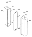
1 to 5 show the concept of the first embodiment. FIG. 1 shows a desulfurizer (a purifier containing device for a fuel cell system) used in a fuel cell system. As shown in FIG. 1, the desulfurizer introduces gaseous fluid fuel, which is used in the fuel cell system and needs to be purified, into the
図1に示すように、中板部材200は金属製であり、互いに背向する平坦な第1表面201および平坦な第2表面202をもつ。中板部材200のうち流れ方向(矢印X1方向)の先端(下端)側にはUターン開口203が形成されている。Uターン開口203は、入口ポート601と出口ポート602との間の中間位置において燃料(流体)をUターンさせるための開口である。図2に示すように、第1流路形成部材300は金属製であり、中板部材200の第1表面201が延びる方向(矢印S1方向)に沿って延設された第1中間壁301と、第1中間壁301の一端側から中板部材200の第1表面201に向けて延設された第1端壁302と、第1中間壁301の他端側から第1端壁302に対向しつつ中板部材200の第1表面201に向けて延設された第1対向壁303とで形成されている。第1流路形成部材300は、横断面でほぼ四角形状の第1流路305を有するように、断面でコの字形状をなす。
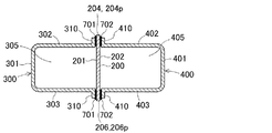
As shown in FIG. 1, the
図2から理解できるように、第2流路形成部材400は金属製であり、中板部材200の第2表面202が延びる方向(矢印S2方向)に沿って延設された第2中間壁401と、第2中間壁401の一端側から中板部材200の第2表面202に向けて延設された第2端壁402と、第2中間壁401の他端側から第2端壁402に対向しつつ中板部材200の第2表面202に向けて延設された第2対向壁403とで形成されている。第2流路形成部材400は、第2流路405を有するコの字形状をなす。図2は、前述したように、燃料の流れ方向に対して交差する方向に切断した断面を示す。図2に示す断面おいて、中板部材200の第1側端部204は、第1流路形成部材300の第1端壁302および第2流路形成部材400の第2端壁402から外方に露出しつつ矢印Y1方向に突出し、第1突出部分204pを形成する。このため、中板部材200の第1表面201に第1流路形成部材300の第1端壁302の側部302sを当接させ易く、且つ、中板部材200の第2表面202に第2流路形成部材400の第2端壁402の側部402sを当接させ易い。図2に示すように、中板部材200の第2側端部206は、第1流路形成部材300の第1対向壁303および第2流路形成部材400の第2対向壁403から外方に露出しつつ矢印Y2方向に突出し、第2突出部分206pを形成する。このため、中板部材200の第1表面201に第1流路形成部材300の第1対向壁303の側部303sを当接させ易く、中板部材200の第2表面202に第2流路形成部材400の第2対向壁403の側部403sを当接させ易い。よって第1流路形成部材300および第2流路形成部材400の組付性が高められる。なお、上記した金属としては、例えば炭素鋼、合金鋼、アルミニウム合金が挙げられる。
As can be understood from FIG. 2, the second flow
図2に示すように、第1流路形成部材300の第1端壁302および第1対向壁303は、中板部材200の第1表面201側にあてがわれて着座され、接合部701で接合されてシールされている。第2流路形成部材400の第2端壁402および第2対向壁403は、中板部材200の第2表面202側にあてがわれて着座され、接合部702で接合されてシールされている。この場合、中板部材200は、第1流路305および第2流路405を有する収容容器500を補強させる補強材としても機能できる。ここで、前述したように、図2に示すごとく、中板部材200の第1側端部204は第1突出部分204pを形成する。中板部材200の第2側端部206は第2突出部分206pを形成する。このため、中板部材200のうち第1流路形成部材300および第2流路形成部材400から外方に突出する第1突出部分204pおよび第2突出部分206pを有効的に利用し、接合部701および接合部702を中板部材200の外側に容易に形成できる利点が得られる。
As shown in FIG. 2, the
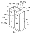
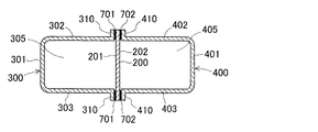
図1に示すように、入口ポート601をもつ第1閉鎖板600は、中板部材200および第1流路形成部材300の長さ方向の一端(上端)側に接合部703により接合されてシールされており、第1流路305の長さ方向の始端を閉鎖させる。出口ポート602をもつ第1閉鎖板600は、中板部材200および第2流路形成部材400の長さ方向の一端(上端)側に接合部704により接合されてシールされており、第2流路405の長さ方向の始端の終端を閉鎖させる。図1に示すように、第2閉鎖板650は底板を形成しており、中板部材200および第2流路形成部材400の長さ方向の他端側に接合部705により接合されてシールされており、第1流路305の始端側および第2流路405の始端側を閉鎖させる。これにより脱硫器を形成する箱状の収容容器500が形成される。
As shown in FIG. 1, the
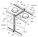
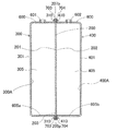
図1に示すように、Uターン開口203を介して第1流路305の終端および第2流路405の始端は連通する。図2に示すように、第1流路形成部材300の第1端壁302および第1対向壁303は、中板部材200の第1表面201側に接合部701で接合されてシールされている。第2流路形成部材400の第2端壁402および第2対向壁403は、中板部材200の第2表面202側に接合部702で接合されてシールされている。そして接合部701,接合部702は外方に露出する。このため接合部701および接合部702の接合状態を視認者は外方から容易に視認できるため、探傷検査せずとも、あるいは、簡単な探傷検査で済み、接合部701,702に対するシール管理が容易となり、接合信頼性を高めることができる。従って、第1流路305と第2流路405との間においてガス状の燃料がショートカット的に漏れることが抑えられる。ひいては燃料が脱硫不充分のまま下流に送られることが抑えられる。なお、接合部701,702は、溶接部またはろう付け部で形成されていることが好ましい。本実施形態によれば、製造にあたっては、図3および図4に示すように、製造過程において、第1流路形成部材300および第2流路形成部材400は、中板部材200を介して互いに対向された状態で、図2に示す接合部701および接合部702で接合されてシールされている。このため、高いシール性を確保させつつ、脱硫器となる収容容器500の組み付けを容易にできる。このように組み付けが容易であるため、接合部701,702のシール不良も抑えられる。よって高いシール性をもつ脱硫器が得られる。
As shown in FIG. 1, the end of the
更に本実施形態によれば、入口ポート601を有する第1閉鎖板600は、第1流路形成部材300および中板部材200に接合部703で接合されてシールされている。出口ポート602を有する第1閉鎖板600は底板を形成し、第2流路形成部材400および中板部材200に接合部704で接合されてシールされている。第2閉鎖板650は、第1流路形成部材300および第2流路形成部材400の端部に接合部705で接合されてシールされている。接合部703、接合部704および接合部705は、図2に示す接合部701および接合部702と同様に、溶接部またはろう付け部で形成されていることが好ましい。
Further, according to the present embodiment, the
加えて本実施形態によれば、図5に示すように、接合部701,702の他に、接合部703、704,705は外方に露出するため、接合部703、704,705の接合状況を視認者により外方から容易に視認できるため、探傷検査せずとも、あるいは、簡単な探傷検査で済み、接合部703,704,705に対する接合信頼性を高めることができる。例えば、上記した各接合部を肉眼で検査しても良いし、石鹸水膜等を接合部に塗布した状態で流体を流せば、漏れにより石鹸水膜が膨張等変形するため、視認が容易となる。なお、図5に示すように、入口ポート601は第1閉鎖板600に接合部601mで接合されてシールされている。出口ポート602は第1閉鎖板600に接合部602mで接合されてシールされている。接合部601m,602mは外方から視認できるため、シール管理が容易である。
In addition, according to the present embodiment, as shown in FIG. 5, in addition to the
さて、容器が脱硫器として使用される場合には、図1に示すように、ゼオライトや活性炭等の脱硫剤520が浄化剤として収容容器500の第1流路305および第2流路405に収容される。燃料電池システムの運転時には、図1から理解できるように、ガス状の燃料が入口ポート601から矢印X1方向に沿って第1流路305に導入され、第1流路305を矢印X2方向に進む。燃料に含まれている硫黄系の付臭剤は、第1流路305の脱硫剤520によって浄化される。その後、燃料は中板部材200のUターン開口203により第1流路305から第2流路405に矢印X3方向にUターンし、更に、ガス状の燃料は第2流路405を矢印X4方向に流れ、第2流路405の脱硫剤によって浄化され、出口ポート602から矢印X5方向に収容容器500の外部の改質器に吐出される。なお、Uターン開口203により燃料がUターンするので、脱硫器の小型化を図りつつ、脱硫距離を確保でき、脱硫性能における信頼性を高め得る。
When the container is used as a desulfurizer, as shown in FIG. 1, a
前述したように、ガス状の燃料に含まれている硫黄成分を除去して燃料を浄化させる脱硫剤520が浄化剤として第1流路305および第2流路405に収容されている。図1に示すように、第1流路305のうち入口ポート601側の余った空間、第2流路405のうち出口ポート602側の余った空間には、脱硫剤の遊動を抑える押さえ部材801,802が配置されている。押さえ部材801,802は、ガス状の燃料を通過させる通気穴801m,802mを有する。押さえ部材801,802により脱硫剤520の揺れ、振動等の遊動が抑制され、脱硫剤520の損傷および微粉化が抑制される。コストを考慮すると、押さえ部材801,802は、ガス透過性をもつ不織布や織布等の織物、布メッシュなどで形成されていることが好ましい。これらは軽量であり、且つ、柔軟性をもつため、運搬時や使用時等において脱硫剤520の振動や衝撃を吸収し易い。不織布や織布等の織物、布メッシュは、不規則的にまとめられて脱硫器に収容される。このため通気穴801m,802mが不規則の多方向に向き、ガス燃料の拡散性を高めることができ、流路305,405における燃料の偏流防止に有利となり、脱硫剤520の利用効率を高めることができる。なお脱硫器以外にも水精製器に適用しても良い。また、第2流路形成部材400側の第1閉塞板600は、「第2閉塞板」に相当する。
As described above, the
(実施形態2)
本実施形態は前記した実施形態1と基本的に同様の構成、同様の作用効果を有するため、図1〜図5を準用できる。ここで、第1流路305は入口ポート601に繋がり、第2流路405は出口ポート602に繋がる。出口ポート602側の第2流路405の終端に配置された第2押さえ部材802の通気穴802mのサイズは、入口ポート601側の第1流路305の始端に配置された第1押さえ部材801の通気穴801mのサイズよりも小さい。この場合、運搬時の衝撃や経年変化等によって仮に脱硫剤が微粉化したときであっても、出口ポート602側の第2押さえ部材802の通気穴802mのサイズは、相対的に小さい。このため微粉化した脱硫剤520がこれの下流側に移動することが抑制される。よって脱硫器の下流において詰まり現象等の不具合を発生させることが抑制される。これに対して、入口側の第1押さえ部材801の通気穴801mのサイズは第2押さえ部材802よりも相対的に大きいため、ガス状の燃料を導入させる通気抵抗が低減される。なお脱硫器以外にも水精製器に適用しても良い。
(Embodiment 2)
Since the present embodiment has basically the same configuration and the same operation and effect as the first embodiment, FIGS. 1 to 5 can be applied mutatis mutandis. Here, the
(実施形態3)
図6は実施形態3を示す。本実施形態は前記した実施形態1と基本的に同様の構成、同様の作用効果を有する。図6に示すように、燃料の流れ方向と交差する方向にそって切断した断面において、中板部材200の第1側端部204は、第1流路形成部材300の第1端壁302および第2流路形成部材400の第2端壁402に対して突出していない。中板部材200の第2側端部206は、第1流路形成部材300の第1対向壁303および第2流路形成部材400の第2対向壁403に対して突出していない。本実施形態においても、接合部701および接合部702は外方に露出する。このため接合部701および接合部702の接合状態を視認者は外方から容易に視認できるため、探傷検査せずとも、あるいは、簡単な探傷検査で済み、シール管理が容易となり、接合部701および接合部702に対する接合信頼性を高めることができる。図5に示す他の接合部703、接合部704、接合部705についても、外方に露出するため、これらの接合状態を視認者は外方から容易に視認できる。図6に示す第1流路形成部材300および第2流路形成部材400は波形部209をもつ。この場合、溶接やろう付け等に起因する歪みの吸収に貢献でき、接合部701,702の保護性を高め得る。波形部209は接合部701,702に近い位置が好ましい。例えば中板部材200の平均厚みの20倍以内、10倍以内が好ましい。なお脱硫器以外にも水精製器に適用しても良い。
(Embodiment 3)
FIG. 6 shows a third embodiment. This embodiment has basically the same configuration and the same function and effect as the first embodiment. As shown in FIG. 6, in the cross section cut along the direction crossing the fuel flow direction, the first
(実施形態4)
図7は実施形態4を示す。本実施形態は前記した実施形態1と基本的に同様の構成、同様の作用効果を有する。図7は、燃料の流れ方向と交差する方向にそって切断した断面を示す。図7に示すように、第1流路形成部材300は断面でC形状をなし、第2流路形成部材400は断面で逆C形状をなす。中板部材200の第1側端部204は流路形成部材300,400から矢印Y1方向に外方に突出すると共に、中板部材200の第2側端部206は流路形成部材300,400から矢印Y2方向に外方に突出する。本実施形態においても、接合部701および接合部702は外方に露出しつつシールしている。このため接合部701および接合部702の接合状態を視認者は外方から容易に視認できるため、接合部701および接合部702に対する接合信頼性を高めることができる。従って、第1流路305と第2流路405との間において燃料がショートカット的に漏れることが抑えられる。図示しないものの、他の接合部についても、外方に露出するため、これらの接合状態を視認者は外方から容易に視認できる。中板部材200、第1流路形成部材300および第2流路形成部材400は波形部209をもつ。この場合、溶接やろう付け等に起因する歪みの吸収に貢献でき、接合部701,702のシール性を更に高め得る。なお脱硫器以外にも水精製器に適用しても良い。
(Embodiment 4)
FIG. 7 shows a fourth embodiment. This embodiment has basically the same configuration and the same function and effect as the first embodiment. FIG. 7 shows a cross section cut along a direction intersecting the fuel flow direction. As shown in FIG. 7, the first flow
(比較形態1)
図8は比較形態の概念を示す。図8に示すように、従来では、脱硫器を大型化させる場合には、複数の独立した収容容器500Bに脱硫剤を装填しつつ、ガス状の燃料をUターンさせるべく、独立した収容容器500Bの先端部同士を連通管550Bで連通させていた。しかしコスト高となる。
(Comparative form 1)
FIG. 8 shows the concept of the comparative form. As shown in FIG. 8, conventionally, when a desulfurizer is enlarged, an
(実施形態5)
図9は実施形態5を示す。本実施形態は前記した実施形態1と基本的に同様の構成、同様の作用効果を有する。但し、本実施形態は改質用の水を浄化させる水精製器に適用している。図9は、流体である水の流れ方向と交差する方向にそって切断した断面を示す。図9に示すように、実施形態1と同様に、第1流路形成部材300の第1端壁302および第1対向壁303は、中板部材200の第1表面201側にあてがわれ、接合部701で接合されてシールされている。第2流路形成部材400の第2端壁402および第2対向壁403は、中板部材200の第2表面202側にあてがわれ、接合部702で接合されてシールされている。接合部701,702は外方に露出して検査が容易となるので、シール管理が容易となる。従って、第1流路305と第2流路405との間において水がショートカット的に漏れることが抑えられ、充分に精製されなかった水が下流に向かうことが抑えられる。中板部材200は、第1流路305および第2流路405を有する収容容器500を補強させる補強材として機能できる。ここで図9に示すように、中板部材200の第1側端部204は外方(矢印Y1方向)に突出する第1突出部分204pを形成する。中板部材200の第2側端部206は外方(矢印Y2方向)に突出する第2突出部分206pを形成する。このため、中板部材200のうち第1流路形成部材300および第2流路形成部材400から外方に突出する第1突出部分204pおよび第2突出部分206pを有効的に利用し、接合部701および接合部702を形成できる利点が得られる。第1流路305および第2流路405には、イオン交換樹脂等で形成された水精製剤625が浄化剤として収容されている。なお水精製器だけでなく脱硫器に適用しても良い。
(Embodiment 5)
FIG. 9 shows a fifth embodiment. This embodiment has basically the same configuration and the same function and effect as the first embodiment. However, this embodiment is applied to a water purifier that purifies reforming water. FIG. 9 shows a cross section cut along a direction intersecting the flow direction of water, which is a fluid. As shown in FIG. 9, similarly to the first embodiment, the
(実施形態6)
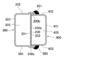
図10は実施形態6を示す。本実施形態は前記した実施形態1と基本的に同様の構成、同様の作用効果を有する。断面を示す図10から理解できるように、中板部材200は、本体200aと、同じ方向に曲成された端部200b,200cを有しており、偏平なほぼコの字形状とされている。断面(図10)において、第1流路形成部材300の第1端壁302および第1対向壁303は、端部200b,200cの外側を覆った状態で、接合部801,802で接合されてシールされている。接合部801,802は外方に露出しているため、検査およびシール管理が容易である。よって第1流路305と第2流路405との間において燃料がショートカット的に漏れることは抑えられる。第2流路形成部材400の第2端壁402および第2対向壁403は、端部200b,200cの内側を覆った状態で、接合部801,802で接合されてシールされている。接合部801,802は外方から視認できるため、接合の適否が容易に視認できる。なお脱硫器以外にも水精製器に適用しても良い。
(Embodiment 6)
FIG. 10 shows a sixth embodiment. This embodiment has basically the same configuration and the same function and effect as the first embodiment. As can be understood from FIG. 10 showing the cross section, the
(実施形態7)
図11は実施形態7を示す。本実施形態は前記した実施形態1と基本的に同様の構成、同様の作用効果を有する。断面を示す図11から理解できるように、中板部材200は、本体200aと、互いに逆方向に曲成された端部200b,200cを有する。断面(図11)において、第1流路形成部材300の第1端壁302は端部200bの外側を覆い、第2流路形成部材400の第2端壁402は端部200bの内側を覆った状態で、接合部801で接合されてシールされている。また、第1流路形成部材300の第1対向壁303は端部200cの内側を覆い、第2流路形成部材400の第2対向壁403は端部200cの外側を覆った状態で、接合部802で接合されてシールされている。図11に示すように、接合部01,802は外方に露出しているため、検査およびシール管理が容易である。従って、第1流路305と第2流路405との間において燃料がショートカット的に漏れることが抑えられる。なお脱硫器以外にも水精製器に適用しても良い。
(Embodiment 7)
FIG. 11 shows a seventh embodiment. This embodiment has basically the same configuration and the same function and effect as the first embodiment. As can be understood from FIG. 11 showing a cross section, the
(実施形態8)
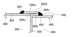
図12は実施形態8を示す。本実施形態は前記した実施形態1と基本的に同様の構成、同様の作用効果を有する。図12は、燃料の流れ方向と交差する方向にそって切断した断面を示す。図12に示すように、中板部材200の第1側端部204XはT字形状に曲成されており、L字形状に辺部200tを曲げる曲成部200uと、Uターン形状に辺部200wを曲げる曲成部200vとを有する。第1流路形成部材300の第1端壁302は第1側端部204X(辺部200w)の内側に嵌合された状態で接合部801により接合されてシールされる。第2流路形成部材400の第2端壁402は第1側端部204X(辺部200t)の内側に嵌合される状態で接合部802により接合されてシールされる。図12に示すように、接合部801,802は外方から視認できるため、接合の適否が容易に視認できる。従って、第1流路305と第2流路405との間において燃料がショートカット的に漏れることが抑えられる。中板部材200の第2側端部についても同様にT字形状に曲成されている。なお脱硫器以外にも水精製器に適用しても良い。
(Embodiment 8)
FIG. 12 shows an eighth embodiment. This embodiment has basically the same configuration and the same function and effect as the first embodiment. FIG. 12 shows a cross section cut along a direction intersecting the fuel flow direction. As shown in FIG. 12, the first
(実施形態9)
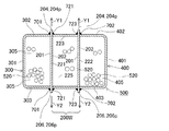
図13は実施形態9を示す。本実施形態は前記した実施形態1と基本的に同様の構成、同様の作用効果を有する。図13は、燃料の流れ方向と交差する方向にそって切断した断面を示す。図13に示すように、第1流路形成部材300は断面でコの字形状をなし、第2流路形成部材400は断面で逆コの字形状をなす。中板部材200Wは、互いに平行に並設された第1中板221および第2中板222と、第1中板221と第2中板222との間に配置された中間流路225を形成する枠状の流路形成部材223とを備える。第1中板221および第2中板222の第1側端部204は、流路形成部材300,400から外方(矢印Y1方向)に突出する。中板部材200Wの第2側端部206は流路形成部材300,400から外方(矢印Y2方向)に突出する。本実施形態においても、接合部701および接合部702は外方に露出する。このため接合部701および接合部702の接合状態を視認者は外方から容易に視認できるため、接合部701および接合部702に対する接合信頼性を高めることができる。図13に示すように、第1中板221と流路形成部材223とは接合部721で接合されてシールされている。第2中板222と流路形成部材223とは接合部723で接合されてシールされている。接合部721,723についても、更には図示しないものの接合部、接合部および接合部についても、外方に露出するため、これらの接合状態を視認者は外方から容易に視認でき、シール管理が容易となる。なお、図示しないものの、第1中板221および第2中板222のうち互いに反対側には、Uターン開口が形成されている。従って第1流路305および第2流路405について燃料は同じ向き方向に流れる。中間流路225については、第1流路305および第2流路405の燃料流れ方向と反対である。なお水精製器に適用しても良い。
(Embodiment 9)
FIG. 13 shows a ninth embodiment. This embodiment has basically the same configuration and the same function and effect as the first embodiment. FIG. 13 shows a cross section cut along a direction intersecting the fuel flow direction. As shown in FIG. 13, the first flow
(実施形態10)
図14〜図17は実施形態10を示す。本実施形態は前記した実施形態1と基本的に同様の構成、同様の作用効果を有する。図14〜図17に示すように、第1流路形成部材300は、板状部材の表面中央部に凹部300Aを形成した構造であり、凹部300Aとその縁部(フランジ部310)とを有している。つまり、第1流路形成部材300の凹部300Aは、図3に示す実施形態1における、第1中間壁301と、第1端壁302と、第1対向壁303と、第1閉鎖板600と、第2閉鎖板650の第1流路305側(底部605a)と、を構成している。フランジ部310は、凹部300Aの縁全周から中板部材200に沿って外方に延設されている。さらに具体的には、フランジ部310は、図5に示す第1端壁302の先端(側部302sの端部)、第1対向壁303の先端(側部303sの端部)、第1閉鎖板600の先端、及び図17に示す底部605aの先端から、中板部材200に沿って外方に延設されている。本実施形態では、フランジ部310は、中板部材200の第1表面201と平行になるように形成されている。
(Embodiment 10)
14 to 17 show the tenth embodiment. This embodiment has basically the same configuration and the same function and effect as the first embodiment. As shown in FIGS. 14 to 17, the first flow
第2流路形成部材400は、本実施形態の第1流路形成部材300と同様の構成であって、凹部400Aとフランジ部410とを有している。凹部400Aは、図3に示す実施形態1における、第2中間壁401と、第2端壁402と、第2対向壁403と、第1閉鎖板600と、第2閉鎖板650の第2流路405側(底部605b)と、を構成している。フランジ部410は、凹部400Aの縁から中板部材200に沿って外方に延設されている。本実施形態では、フランジ部410は、中板部材200の第2表面202と平行になるように形成されている。第1流路形成部材300及び第2流路形成部材400は、例えばプレスを用いた深絞り加工により形成することができる。
The second flow
図16及び図17に示すように、第1流路形成部材300のフランジ部310は、中板部材200の第1表面201側にあてがわれて着座され、接合部701、703で接合されてシールされている。第2流路形成部材400のフランジ部410は、中板部材200の第2表面202側にあてがわれて着座され、接合部702、704で接合されてシールされている。中板部材200は、第1流路形成部材300及び第2流路形成部材400の外方に突出する第1突出部分204p、第2突出部分206p、第3突出部分207p(第1閉塞板600側)、及び第4突出部分208p(長板650側)を備えている。このため、接合部701〜704を中板部材200に容易に形成できる利点が得られる。
As shown in FIGS. 16 and 17, the
本実施形態によれば、流路形成部材300、400にフランジ部310、410が
形成されており、接合部701〜704に対する流路形成部材300、400及び中板部材200の接触面積を大きくすることが可能となる。接合部701〜704と両部材との接触面積を大きくすることで、シール性をより安定させることができる。例えば、収容装置(脱硫器等)が大型化しても本実施形態によれば高いシール性が確保される。また、当該接触面積が大きいことで、流路形成部材300、400の中板部材200への組み付けを容易にかつ安定して行うことができる。つまり、本実施形態によれば組み付け作業の作業性も向上する。また、フランジ部310、410と中板部材200とを平行にすることで、組み付け時のガタつきが防止され、組み付け作業時の部材の安定性や接合後のシールの安定性も向上させることができる。
According to the present embodiment, the
また、接合部を用いずプレス加工により成型された流路形成部材300、400には、フランジ部310、410により曲げ部分が形成されている。つまり、凹部300A、400Aの縁には、板状部材が屈曲した曲げ部分が形成されている。これにより、流路形成部材300、400の剛性が高くなり、結果として収容装置の剛性が向上する。また、接合部701〜704が外方に露出しているため、他の実施形態同様の効果が発揮される。接合部701〜704は、溶接又はろう付けにより形成されることが好ましい。また、本実施形態によれば、流路形成部材300,400の製造において接合部が必要なく、プレス加工を利用することができ、製造効率も向上する。
In addition, the flow
このように、本実施形態は、シールの安定性、剛性、大型化への対応、及び製造の観点で優れている。なお、図18に示すように、中板部材200は、突出部分を有しないものでも良い。また、接合部701〜704は、外方に露出していなくても良い。
Thus, this embodiment is excellent in terms of stability, rigidity, response to an increase in size, and manufacturing. As shown in FIG. 18, the
(適用形態1)
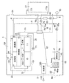
図19は、上記した脱硫器および水精製器を適用した適用形態1の概念を示す。図19において、脱硫器62は上記した実施形態に係る脱硫器で形成されている。水精製器43は上記した水精製器で形成されている。図19に示すように、燃料電池システムは、燃料電池1と、液相状の水を蒸発させて水蒸気を生成させる蒸発部2と、蒸発部2で生成された水蒸気を用いて燃料を改質させてアノード流体を形成する改質部3と、蒸発部2に供給される液相状の水を溜めるタンク4と、これらを収容するケース5とを有する。燃料電池1は、イオン伝導体を挟むアノード10とカソード11とをもち、例えば、SOFCとも呼ばれる固体酸化物形燃料電池(運転温度:例えば400℃以上)を適用できる。アノード10側から排出されたアノード排ガスはアノード排ガス路103を介して、燃焼部105に供給される。カソード11側から排出されたカソード排ガスはカソード排ガス路104を介して、燃焼部105に供給される。燃焼部105は前記アノード排ガスとカソード排ガスとを燃焼させ蒸発部2と改質部3を加熱させる。燃焼部105には燃焼排ガス路75が設けられ、燃焼部105における燃焼後のガスおよび、未燃焼のガスを含む燃焼排ガスが燃焼排ガス路75を介して大気中に放出される。改質部3は、セラミックス等の担体に改質触媒を担持させて形成されており、蒸発部2に隣設されている。改質部3および蒸発部2は改質器2Aを構成しており、燃料電池1と共に断熱壁19で包囲され、発電モジュール18を形成している。改質部3の内部には、改質部3の温度を検知する温度センサ33が、燃焼部105の内部には、燃料を着火させるヒータである着火部35が設けられている。着火部35は改質部3の燃料に着火できるものであれば何でも良い。温度センサ33の信号は制御部100に入力される。制御部100は着火部35を作動させて燃焼部105を着火させて高温化させる。制御部100は異状があれば、報知器102に異状信号を報知する。
(Application 1)
FIG. 19 shows the concept of
発電運転時には、改質器2Aは改質反応に適するように断熱壁19内において加熱される。発電運転時には、蒸発部2は水を加熱させて水蒸気とさせ得るように加熱される。燃料電池1がSOFCタイプの場合には、アノード10において燃料またはアノード流体を燃焼させて燃料電池1のアノード10およびカソード11が加熱されるため、改質部3および蒸発部2は同時に加熱される。燃料通路6は、燃料源63からの燃料を改質器2Aに供給させるものであり、燃料ポンプ60および脱硫器62をもつ。燃料電池1のカソード11には、カソード流体(空気)をカソード11に供給させるためのカソード流体通路70が繋がれている。カソード流体通路70には、カソード流体搬送用の水搬送源として機能するカソードポンプ71が設けられている。
During the power generation operation, the
図19に示すように、ケース5は外気に連通する吸気口50と排気口51とをもち、更に、第1室である上室空間52と、第2室である下室空間53とをもつ。燃料電池1は、改質部3および蒸発部2と共に、ケース5の上側つまり上室空間52に収容されている。ケース5の下室空間53には、改質部3で改質される液相状の水を溜めるタンク4が収容されている。タンク4には、電気ヒータ等の加熱機能をもつ加熱部40が設けられている。加熱部40は、タンク4に貯留されている水を加熱させるものであり、電気ヒータ等で形成できる。外気温度等の環境温度が低いとき等には、制御部100からの指令に基づいて、タンク4の水は加熱部40により所定温度(例えば5℃、10℃、20℃)以上に加熱され、凍結が抑制される。図19に示すように、下室空間53側のタンク4の出口ポート4pと上室空間52側の蒸発部2の入口ポート2iとを連通させる給水通路8が、配管としてケース5内に設けられている。図19に示すように、給水通路8は、タンク4内に溜められている水をタンク4の入口ポート2iから蒸発部2に供給させる通路である。給水通路8には、タンク4内の水を蒸発部2まで搬送させる水搬送源として機能するポンプ80が設けられている。ポンプ80は、正方向に回転駆動してタンク4内の水を出口ポート4pから蒸発部2の入口ポート2iに向けて搬送させる正モードを実行可能とされている。ポンプ80などを駆動回路を介して制御するための制御部100が設けられている。制御部100はポンプ71,79,60を制御する。
As shown in FIG. 19, the case 5 has an
システムの運転時において、ポンプ80が駆動すると、タンク4内の水は、タンク4の出口ポート4pから蒸発部2の入口ポート2iに向けて給水通路8内を搬送され、蒸発部2で加熱されて水蒸気とされる。水蒸気は燃料通路6から供給される燃料(ガス状が好ましいが、場合によっては液相状としても良い)と共に改質部3に移動する。改質部3において燃料は、水蒸気で改質されてアノード流体(水素含有ガス)となる。アノード流体はアノード流体通路73を介して燃料電池1のアノード10に供給される。更にカソード流体(酸素含有ガス、ケース5内の空気)がカソード流体通路70を介して燃料電池1のカソード11に供給される。これにより燃料電池1が発電する。燃料電池1で排出された高温の排ガスは、排ガス通路75を介してケース5の外方に排出される。
When the
排ガス通路75には、凝縮機能をもつ熱交換器76が設けられている。貯湯槽77に繋がる貯湯通路78および貯湯ポンプ79が設けられている。貯湯通路78は往路78aおよび復路78cをもつ。貯湯槽77の低温の水は、貯湯ポンプ79の駆動により、貯湯槽77の吐出ポート77pから吐出されて往路78aを通過し、熱交換器76に至り、熱交換器76の熱交換作用により加熱される。熱交換器76で加熱された水は、復路78cを介して帰還ポート77iから貯湯槽77に帰還する。このようにして貯湯槽77の水は温水となる。前記した排ガスに含まれていた水蒸気は、熱交換器76で凝縮されて凝縮水となる。凝縮水は、熱交換器76から延設された凝縮水通路42を介して重力等により水精製器43に供給される。水精製器43はイオン交換樹脂等の水精製剤43aを有するため、凝縮水の不純物は除去される。不純物が除去された水は水タンク4に移動し、水タンク4に溜められる。ポンプ80が正モードで駆動すると、水タンク4内の水は給水通路8を介して高温の蒸発部2に供給され、蒸発部2で水蒸気とされて改質部3に供給され、改質部3において燃料を改質させる改質反応として消費される。本形態によれば、脱硫器および水精製器において、必ずしもシール性が良好ではない接合部を燃料や水等の流体が第1流路と第2流路との間において中板部材を介して第1ショートカット的に透過することが抑制される。よって、燃料を脱硫剤で充分に浄化させることができる。また、水を精製剤で充分に浄化させることができる。このため脱硫剤や水精製剤で充分に浄化されなかった燃料や水が出口ポートからこれの下流機器(例えば改質器または燃料電池)に吐出されることが抑制され、システムの長期にわたる信頼性が高められる。
A
(適用形態2)
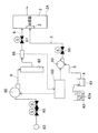
図20は適用形態2の概念を示す。図19に示すように、燃料源63から改質器2Aに向かう燃料通路6が設けられている。燃料通路6には、二連式の燃料バルブ65、燃料ポンプ60,脱硫器62,流量センサ66,入口バルブ67が直列に配置されている。更に改質器2Aの蒸発部2に向かう給水通路8が設けられている。給水通路8には、水精製剤43aを収容させる水精製器43,水精製器43で精製させた水を貯留するタンク4,水搬送源として機能するポンプ80,入口バルブ89が設けられている。制御装置100は信号線を介して燃料ポンプ60を,入口バルブ67,89、ポンプ80を制御する。流量センサ66の検知信号は制御部100に入力される。
(Application 2)
FIG. 20 shows the concept of
(その他)
本発明は上記し且つ図面に示した各実施形態および適用形態のみに限定されるものではなく、要旨を逸脱しない範囲内で適宜変更して実施できる。実施形態1では、図1および図2に示す中板部材200のうち第1流路形成部材300および第2流路形成部材400から外方に突出する第1突出部分204pおよび第2突出部分206pを利用して、接合部701および接合部702を形成しているが、場合によっては、第1突出部分204pおよび第2突出部分206pはなくても良い。押さえ部材801,802は織物等とされているが、金属バネとしても良い。図19に示す燃料電池1は、固体高分子形燃料電池、リン酸形燃料電池、溶融炭酸塩形燃料電池でも良い。要するに、燃料を脱硫させる脱硫器を有する燃料電池システムであれば良い。燃料も特に制限されず、都市ガス、プロパンガス、バイオガス、LPG、CNG、灯油、ガソリン、アルコール等を利用できる。
(Other)
The present invention is not limited to only the embodiments and application modes described above and shown in the drawings, and can be implemented with appropriate modifications within a range not departing from the gist. In the first embodiment, the first projecting portion 204p and the second projecting portion 206p projecting outward from the first flow
(付記項1)燃料電池システムで用いられるガス状または液相状の浄化用の流体を入口ポートから導入してUターンさせた後に出口ポートから外部に導出させる燃料電池システム用浄化剤収容装置であって、流体を浄化させるための浄化剤が第1流路および第2流路に収容されており、前記第1流路および/または前記第2流路の余った空間に、流体を通過させる通気穴を有すると共に前記浄化剤の遊動を抑える押さえ部材が配置されている燃料電池システム用浄化剤収容装置。 (Additional Item 1) A purifier containing device for a fuel cell system in which a gaseous or liquid phase purification fluid used in a fuel cell system is introduced from an inlet port and U-turned and then led out from the outlet port. A purifying agent for purifying the fluid is accommodated in the first flow path and the second flow path, and allows the fluid to pass through the remaining space of the first flow path and / or the second flow path. A purifier containing device for a fuel cell system having a vent hole and a pressing member that suppresses the movement of the purifier.
(付記項2)付記項1において、前記第1流路は前記入口ポートに繋がり、前記第2前記出口ポートに繋がり、前記第2流路に配置された前記押さえ部材の通気穴のサイズは、前記第2流路に配置された前記押さえ部材の通気穴のサイズよりも小さい燃料電池システム用浄化剤収容装置。
(Additional Item 2) In
1は燃料電池、10はアノード、11はカソード、2Aは改質器、2は蒸発部、3は改質部、33は温度センサ、4はタンク、70はカソード流体通路、73はアノード流体通路、75は排ガス通路、77は貯湯槽、8は給水通路、80はポンプ(水搬送源)、100は制御部を示し、更に、200は中板部材、201は第1表面、202は第2表面、203はUターン開口、204は第1側端部、206は第2側端部、204pは第1突出部分、206pは第2突出部分、300は第1流路形成部材、305は第1流路、400は第2流路形成部材、405は第2流路、500は収容容器、520は脱硫剤(浄化剤)、水精製剤625(浄化剤)、310及び410はフランジ部を示す。 1 is a fuel cell, 10 is an anode, 11 is a cathode, 2A is a reformer, 2 is an evaporator, 3 is a reformer, 33 is a temperature sensor, 4 is a tank, 70 is a cathode fluid passage, and 73 is an anode fluid passage. , 75 is an exhaust gas passage, 77 is a hot water storage tank, 8 is a water supply passage, 80 is a pump (water conveyance source), 100 is a control unit, 200 is an intermediate plate member, 201 is a first surface, and 202 is a second surface. Surface, 203 is U-turn opening, 204 is first side end, 206 is second side end, 204p is first projecting portion, 206p is second projecting portion, 300 is first flow path forming member, 305 is first 1 channel, 400 is a second channel forming member, 405 is a second channel, 500 is a container, 520 is a desulfurizing agent (purifying agent), water purifying agent 625 (purifying agent), 310 and 410 are flange portions. Show.
Claims (8)
前記入口ポートと前記出口ポートとの間において流体をUターンさせるためのUターン開口と互いに背向する第1表面および第2表面とをもつ中板部材と、
前記流体が流れる第1流路を形成する第1流路形成部材と、
前記Uターン開口を介して前記第1流路に連通する第2流路を形成する第2流路形成部材とを具備しており、
前記第1流路形成部材は前記中板部材の前記第1表面側にあてがわれて接合部で接合され、前記第2流路形成部材は前記中板部材の前記第2表面側にあてがわれて接合部で接合されてシールされている燃料電池システム用浄化剤収容装置。 A purifying agent storage device for a fuel cell system that introduces a gas or liquid phase purification fluid used in a fuel cell system from an inlet port and makes a U-turn, and then leads out from the outlet port to the outside.
An intermediate plate member having a U-turn opening for U-turning fluid between the inlet port and the outlet port, and first and second surfaces facing each other;
A first flow path forming member that forms a first flow path through which the fluid flows;
A second flow path forming member that forms a second flow path that communicates with the first flow path through the U-turn opening;
The first flow path forming member is applied to the first surface side of the intermediate plate member and bonded at a joint portion, and the second flow path forming member is applied to the second surface side of the intermediate plate member. A purifier containing device for a fuel cell system that is joined and sealed at a joint.
前記中板部材、前記第1流路形成部材および前記第2流路形成部材の前記流体流れ方向の他端側に接合され、前記第1流路および前記第2流路の長さ方向の他端を閉鎖させる第2閉鎖板とが設けられている燃料電池システム用浄化剤収容装置。 In one of Claims 1-3, it joins to the one end side of the said fluid flow direction of the said intermediate | middle plate member, the said 1st flow path formation member, and the said 2nd flow path formation member, The said 1st flow path and A first closing plate for closing one end in the length direction of the second flow path;
Joined to the other end side of the fluid flow direction of the intermediate plate member, the first flow path forming member, and the second flow path forming member, and the other in the length direction of the first flow path and the second flow path A purifier containing device for a fuel cell system provided with a second closing plate for closing the end.
Priority Applications (2)
| Application Number | Priority Date | Filing Date | Title |
|---|---|---|---|
| JP2012004261A JP5812345B2 (en) | 2011-01-24 | 2012-01-12 | Purifier containing device for fuel cell system and fuel cell system |
| EP12152050.6A EP2479828B1 (en) | 2011-01-24 | 2012-01-23 | Depurant container device for fuel cell system and fuel cell system including thereof |
Applications Claiming Priority (3)
| Application Number | Priority Date | Filing Date | Title |
|---|---|---|---|
| JP2011011638 | 2011-01-24 | ||
| JP2011011638 | 2011-01-24 | ||
| JP2012004261A JP5812345B2 (en) | 2011-01-24 | 2012-01-12 | Purifier containing device for fuel cell system and fuel cell system |
Publications (2)
| Publication Number | Publication Date |
|---|---|
| JP2012169262A true JP2012169262A (en) | 2012-09-06 |
| JP5812345B2 JP5812345B2 (en) | 2015-11-11 |
Family
ID=45531222
Family Applications (1)
| Application Number | Title | Priority Date | Filing Date |
|---|---|---|---|
| JP2012004261A Active JP5812345B2 (en) | 2011-01-24 | 2012-01-12 | Purifier containing device for fuel cell system and fuel cell system |
Country Status (2)
| Country | Link |
|---|---|
| EP (1) | EP2479828B1 (en) |
| JP (1) | JP5812345B2 (en) |
Cited By (3)
| Publication number | Priority date | Publication date | Assignee | Title |
|---|---|---|---|---|
| JP2015187981A (en) * | 2014-03-14 | 2015-10-29 | パナソニック株式会社 | Fuel battery system |
| JP2016072057A (en) * | 2014-09-30 | 2016-05-09 | アイシン精機株式会社 | Suction device for fuel cell and fuel cell system |
| JP2016207492A (en) * | 2015-04-23 | 2016-12-08 | アイシン精機株式会社 | Purifier for fuel cell system |
Citations (10)
| Publication number | Priority date | Publication date | Assignee | Title |
|---|---|---|---|---|
| JPS56142149A (en) * | 1980-04-02 | 1981-11-06 | Tada Kk | Enameled tank and its manufacture |
| JPS5883298A (en) * | 1981-10-28 | 1983-05-19 | ドイツチエ・ゲゼルシヤフト・フユ−ル・ヴイ−ダ−アウフアルバイツンク・フオン・ケルンブレンシユトツフエン・ミツト・ベシユレンクテル・ハフツング | Vessel for transporting and or storing nuclear fuel element |
| JPH02113569A (en) * | 1988-10-22 | 1990-04-25 | Sony Corp | Manufacture of storage device |
| JPH02113569U (en) * | 1989-02-28 | 1990-09-11 | ||
| JP2005085481A (en) * | 2003-09-04 | 2005-03-31 | Nissan Motor Co Ltd | Fuel cell system |
| JP2005297713A (en) * | 2004-04-09 | 2005-10-27 | Futaba Industrial Co Ltd | Fuel tank and manufacturing method therefor |
| JP2006142329A (en) * | 2004-11-18 | 2006-06-08 | Toyota Motor Corp | Container made of stainless steel, and its manufacturing method |
| JP2007090321A (en) * | 2005-09-01 | 2007-04-12 | Osaka Gas Co Ltd | Fluid treatment apparatus and manufacturing method thereof |
| JP2008117652A (en) * | 2006-11-06 | 2008-05-22 | Fuji Electric Holdings Co Ltd | Desulfurizer for fuel cell power generation |
| JP2010067353A (en) * | 2008-09-08 | 2010-03-25 | Honda Motor Co Ltd | Desulfurizer |
Family Cites Families (4)
| Publication number | Priority date | Publication date | Assignee | Title |
|---|---|---|---|---|
| US3898049A (en) * | 1971-10-05 | 1975-08-05 | Texaco Inc | Hydrogenation reactors with improved flow distribution |
| JP2003269802A (en) * | 2002-03-14 | 2003-09-25 | Hitachi Housetec Co Ltd | Structure for mounting air straightening plate of combustor |
| JP2005095543A (en) | 2003-09-24 | 2005-04-14 | Kanechu Kk | Top opened footwear |
| JP5085048B2 (en) | 2006-03-30 | 2012-11-28 | 京セラ株式会社 | Desulfurization apparatus and method of using the same |
-
2012
- 2012-01-12 JP JP2012004261A patent/JP5812345B2/en active Active
- 2012-01-23 EP EP12152050.6A patent/EP2479828B1/en not_active Not-in-force
Patent Citations (11)
| Publication number | Priority date | Publication date | Assignee | Title |
|---|---|---|---|---|
| JPS56142149A (en) * | 1980-04-02 | 1981-11-06 | Tada Kk | Enameled tank and its manufacture |
| JPS5883298A (en) * | 1981-10-28 | 1983-05-19 | ドイツチエ・ゲゼルシヤフト・フユ−ル・ヴイ−ダ−アウフアルバイツンク・フオン・ケルンブレンシユトツフエン・ミツト・ベシユレンクテル・ハフツング | Vessel for transporting and or storing nuclear fuel element |
| JPH02113569A (en) * | 1988-10-22 | 1990-04-25 | Sony Corp | Manufacture of storage device |
| JPH02113569U (en) * | 1989-02-28 | 1990-09-11 | ||
| JP2005085481A (en) * | 2003-09-04 | 2005-03-31 | Nissan Motor Co Ltd | Fuel cell system |
| JP2005297713A (en) * | 2004-04-09 | 2005-10-27 | Futaba Industrial Co Ltd | Fuel tank and manufacturing method therefor |
| JP2006142329A (en) * | 2004-11-18 | 2006-06-08 | Toyota Motor Corp | Container made of stainless steel, and its manufacturing method |
| JP2007090321A (en) * | 2005-09-01 | 2007-04-12 | Osaka Gas Co Ltd | Fluid treatment apparatus and manufacturing method thereof |
| JP2008117652A (en) * | 2006-11-06 | 2008-05-22 | Fuji Electric Holdings Co Ltd | Desulfurizer for fuel cell power generation |
| JP2010067353A (en) * | 2008-09-08 | 2010-03-25 | Honda Motor Co Ltd | Desulfurizer |
| US20110165477A1 (en) * | 2008-09-08 | 2011-07-07 | Honda Motor Co., Ltd. | Desulfurizer |
Cited By (3)
| Publication number | Priority date | Publication date | Assignee | Title |
|---|---|---|---|---|
| JP2015187981A (en) * | 2014-03-14 | 2015-10-29 | パナソニック株式会社 | Fuel battery system |
| JP2016072057A (en) * | 2014-09-30 | 2016-05-09 | アイシン精機株式会社 | Suction device for fuel cell and fuel cell system |
| JP2016207492A (en) * | 2015-04-23 | 2016-12-08 | アイシン精機株式会社 | Purifier for fuel cell system |
Also Published As
| Publication number | Publication date |
|---|---|
| EP2479828A1 (en) | 2012-07-25 |
| EP2479828B1 (en) | 2016-08-24 |
| JP5812345B2 (en) | 2015-11-11 |
Similar Documents
| Publication | Publication Date | Title |
|---|---|---|
| JP5162118B2 (en) | Fuel cell system | |
| US8808939B2 (en) | Fuel cell stack and fuel cell cogeneration system including the same | |
| KR20090089859A (en) | Fuel cell heat exchange systems and methods | |
| JP5812345B2 (en) | Purifier containing device for fuel cell system and fuel cell system | |
| JP5372980B2 (en) | Fuel cell system | |
| JP5302991B2 (en) | Fuel cell system | |
| JP5618144B2 (en) | Purifier containing device for fuel cell system and fuel cell system | |
| JP5048870B2 (en) | Fuel cell system and operation method thereof | |
| US20220149393A1 (en) | Assembly for an electrochemical system, stack, and electrochemical system | |
| US9543597B2 (en) | Fuel-cell power generation system and method of manufacturing the same | |
| US20100221618A1 (en) | Enclosed Separator Unit for a Gas Supply of a Fuel Cell System | |
| JP5904828B2 (en) | Fuel cell device | |
| JP4735393B2 (en) | Heat exchanger and heat exchange type reformer | |
| JP6178979B2 (en) | Fuel processor | |
| JP7255455B2 (en) | Pipe module for ejector | |
| JP6587096B2 (en) | Solid oxide fuel cell device | |
| JP5946730B2 (en) | Fuel cell module | |
| JP2009266610A (en) | Fuel cell system | |
| JP2003187839A (en) | Fuel cell humidifier | |
| CN116264298A (en) | Confluence mechanism and fuel cell system | |
| JP5768996B2 (en) | Fuel cell system piping structure | |
| JP5218232B2 (en) | Fuel cell | |
| JP5182982B2 (en) | Fuel cell reforming system | |
| JP2007317617A (en) | Fuel cell unit | |
| JP2016207492A (en) | Purifier for fuel cell system |
Legal Events
| Date | Code | Title | Description |
|---|---|---|---|
| A621 | Written request for application examination |
Free format text: JAPANESE INTERMEDIATE CODE: A621 Effective date: 20140507 |
|
| A977 | Report on retrieval |
Free format text: JAPANESE INTERMEDIATE CODE: A971007 Effective date: 20150218 |
|
| A131 | Notification of reasons for refusal |
Free format text: JAPANESE INTERMEDIATE CODE: A131 Effective date: 20150226 |
|
| A521 | Written amendment |
Free format text: JAPANESE INTERMEDIATE CODE: A523 Effective date: 20150420 |
|
| A131 | Notification of reasons for refusal |
Free format text: JAPANESE INTERMEDIATE CODE: A131 Effective date: 20150702 |
|
| A521 | Written amendment |
Free format text: JAPANESE INTERMEDIATE CODE: A523 Effective date: 20150804 |
|
| TRDD | Decision of grant or rejection written | ||
| A01 | Written decision to grant a patent or to grant a registration (utility model) |
Free format text: JAPANESE INTERMEDIATE CODE: A01 Effective date: 20150825 |
|
| A61 | First payment of annual fees (during grant procedure) |
Free format text: JAPANESE INTERMEDIATE CODE: A61 Effective date: 20150909 |
|
| R150 | Certificate of patent or registration of utility model |
Ref document number: 5812345 Country of ref document: JP Free format text: JAPANESE INTERMEDIATE CODE: R150 |
|
| R250 | Receipt of annual fees |
Free format text: JAPANESE INTERMEDIATE CODE: R250 |
|
| R250 | Receipt of annual fees |
Free format text: JAPANESE INTERMEDIATE CODE: R250 |
|
| R250 | Receipt of annual fees |
Free format text: JAPANESE INTERMEDIATE CODE: R250 |