JP2012167617A - Control device of multi-cylinder internal combustion engine - Google Patents
Control device of multi-cylinder internal combustion engine Download PDFInfo
- Publication number
- JP2012167617A JP2012167617A JP2011029959A JP2011029959A JP2012167617A JP 2012167617 A JP2012167617 A JP 2012167617A JP 2011029959 A JP2011029959 A JP 2011029959A JP 2011029959 A JP2011029959 A JP 2011029959A JP 2012167617 A JP2012167617 A JP 2012167617A
- Authority
- JP
- Japan
- Prior art keywords
- cylinder
- fuel injection
- fuel
- pressure
- internal combustion
- Prior art date
- Legal status (The legal status is an assumption and is not a legal conclusion. Google has not performed a legal analysis and makes no representation as to the accuracy of the status listed.)
- Granted
Links
Images


Landscapes
- Electrical Control Of Air Or Fuel Supplied To Internal-Combustion Engine (AREA)
- Combined Controls Of Internal Combustion Engines (AREA)
Abstract
Description
本発明は、多気筒内燃機関の制御装置に関するものである。 The present invention relates to a control device for a multi-cylinder internal combustion engine.
多気筒内燃機関では、クランクセンサやカムセンサの検出信号に基づいて燃焼行程を迎える気筒の特定(いわゆる気筒判別)を行うとともに、その結果をもとに各気筒の燃料噴射弁の開弁駆動がそれぞれ適当なタイミングで実行される。 In a multi-cylinder internal combustion engine, cylinders that reach the combustion stroke are identified based on the detection signals of the crank sensor and cam sensor (so-called cylinder discrimination), and the fuel injection valves of each cylinder are driven to open based on the results. It is executed at an appropriate timing.
また多気筒の内燃機関において、燃料噴射の実行時における燃料供給経路内の燃料圧力を検出するとともに、同燃料圧力の変動波形に基づいて燃料噴射弁の作動特性(例えば噴射量誤差や開弁遅れ時間、閉弁遅れ時間)を検出する装置が提案されている(特許文献1参照)。こうした装置において、気筒毎に設けられた燃料噴射弁の作動特性を効率良く検出するためには、燃料噴射の開始前に燃料噴射が実行される燃料噴射弁、すなわち燃焼行程になる気筒を認識しておく必要がある。特許文献1に記載の装置では、気筒判別の結果をもとに燃焼行程になる気筒を特定したうえで、気筒毎に、燃料供給経路内の燃料圧力の検出と同燃料圧力の変動波形に基づく燃料噴射弁の作動特性の検出とが行われる。
In a multi-cylinder internal combustion engine, the fuel pressure in the fuel supply path during fuel injection is detected, and the operating characteristics of the fuel injection valve (for example, injection amount error or valve opening delay) based on the fluctuation waveform of the fuel pressure. A device for detecting time and valve closing delay time has been proposed (see Patent Document 1). In such a device, in order to efficiently detect the operating characteristics of the fuel injection valve provided for each cylinder, the fuel injection valve in which fuel injection is performed before the start of fuel injection, that is, the cylinder that is in the combustion stroke is recognized. It is necessary to keep. In the device described in
内燃機関にはその周辺機器としての電子制御ユニットが設けられている。そして、この電子制御ユニットに内蔵された中央処理装置(CPU)により、燃料噴射弁の駆動制御のための処理や気筒判別のための処理などといった機関運転のための各種の演算処理が実行される。 The internal combustion engine is provided with an electronic control unit as its peripheral equipment. Various arithmetic processes for engine operation such as a process for driving control of the fuel injection valve and a process for cylinder discrimination are executed by a central processing unit (CPU) built in the electronic control unit. .
また近年、同一の電子制御ユニット内に、対象となる演算処理毎に設定された専用のCPUを複数設けることが提案されている。仮に、こうした装置を上記特許文献1に記載の装置に適用する場合には、燃料噴射弁の駆動制御のための処理を実行するメインCPUとは別に、燃料圧力の変動波形の検出を行うためのサブCPUを設けることが考えられる。
In recent years, it has been proposed to provide a plurality of dedicated CPUs set for each target arithmetic processing in the same electronic control unit. If such a device is applied to the device described in
この場合、気筒判別のための演算処理をメインCPUに実行させることに加えてサブCPUにも実行させることにより、各気筒の燃料噴射弁の開弁駆動と燃料圧力の検出とがそれぞれ適切なタイミングで実行されるようになる。ただし気筒判別のための演算処理は、単にクランクセンサやカムセンサの検出信号を取り込むだけの処理ではなく、クランクセンサの検出信号とカムセンサの検出信号との関係に基づいて機関出力軸の回転位相を特定するといった煩雑な処理であるために、その演算負荷が大きくなり易い。そのため、そうした気筒判別にかかる処理をメインCPUとサブCPUとの双方において実行することは効率が悪く、望ましくない。 In this case, in addition to causing the main CPU to execute calculation processing for cylinder discrimination, the sub CPU executes the calculation processing so that the fuel injection valve opening drive and the fuel pressure detection of each cylinder are performed at appropriate timings. Will be executed. However, the calculation process for cylinder discrimination is not simply a process of capturing the detection signal of the crank sensor or cam sensor, but the rotational phase of the engine output shaft is specified based on the relationship between the detection signal of the crank sensor and the detection signal of the cam sensor. Since this is a complicated process, the calculation load tends to increase. For this reason, it is inefficient and not desirable to execute such processing for cylinder discrimination in both the main CPU and the sub CPU.
なお、こうした気筒判別の実行についての不都合は、実行対象となる気筒の特定と同気筒についての演算処理とを行うCPUを複数備えた装置においては同様に生じる。
本発明は、そうした実情に鑑みてなされたものであり、その目的は、二つの中央処理装置の演算負荷を小さく抑えつつ、それら中央処理装置による気筒毎の演算処理をそれぞれ適切なタイミングで実行することのできる多気筒内燃機関の制御装置を提供することにある。
Such inconvenience in executing the cylinder discrimination similarly occurs in an apparatus including a plurality of CPUs that perform specification of a cylinder to be executed and calculation processing for the cylinder.
The present invention has been made in view of such circumstances, and an object of the present invention is to execute calculation processing for each cylinder by the central processing units at appropriate timings while suppressing the calculation load of the two central processing units to be small. An object of the present invention is to provide a control device for a multi-cylinder internal combustion engine capable of performing
以下、上記目的を達成するための手段及びその作用効果について説明する。
請求項1に記載の構成では、多気筒内燃機関に第1中央処理装置(第1CPU)および第2中央処理装置(第2CPU)を有する電子制御ユニットが設けられる。そして、第1CPUによって気筒判別を行う演算処理が実行されるとともに、その結果に基づいて燃料噴射弁を開弁駆動するための駆動パルスが気筒毎に設けられた燃料噴射弁のいずれかに対して選択的に出力される。これにより、各燃料噴射弁に対してそれぞれ適切なタイミングで駆動パルスが出力されるようになる。また第1CPUから駆動パルスを出力することに加えて、予め定められた時期(機関出力軸の所定回転位相)において燃料噴射弁を開弁させないパルス幅のダミーパルスが出力される。そして、このダミーパルスが第2CPUに入力されることにより、このときの機関出力軸の回転位相を同第2CPUに把握させることが可能になるため、その把握した回転位相をもとに演算処理の実行対象となる気筒を特定することが可能になり、その特定した気筒についての演算処理を実行することも可能になる。なお、上記ダミーパルスは各燃料噴射弁に対して出力されるとはいえ、ダミーパルスのパルス幅は燃料噴射弁を開弁させない長さに設定されるため、ダミーパルスが入力されたことをもって燃料噴射弁が不要に開弁駆動されることはない。
In the following, means for achieving the above object and its operational effects will be described.
In the configuration described in
このように上記構成によれば、第1CPUと第2CPUとにおいて共に実行対象となる気筒の特定と同気筒についての演算処理とが実行されるものの、第1CPUによる気筒判別の結果をもとに第2CPUによる演算処理を適正に行うことができる。したがって、第1CPUおよび第2CPUの双方において気筒判別を行うための演算処理を実行する装置と比較して演算負荷を小さく抑えつつ、それらCPUにおける気筒毎の演算処理をそれぞれ適切なタイミングで実行することができる。 As described above, according to the above configuration, although the first CPU and the second CPU both execute the identification of the cylinder to be executed and the arithmetic processing for the cylinder, the first CPU and the second CPU execute the first discrimination based on the result of the cylinder discrimination by the first CPU. Arithmetic processing by two CPUs can be performed appropriately. Therefore, both the first CPU and the second CPU execute the arithmetic processing for each cylinder in the CPU at an appropriate timing while suppressing the arithmetic load as compared with a device that executes arithmetic processing for performing cylinder discrimination. Can do.
燃料噴射弁内部の燃料圧力は、燃料噴射弁の開弁に伴って低下するとともにその後における同燃料噴射弁の閉弁に伴って上昇するといったように、燃料噴射弁の開閉動作に伴い変動する。そのため、燃料噴射の実行時における燃料圧力の変動波形を監視することにより、燃料噴射弁の実動作特性(例えば、開弁動作が開始される時期や閉弁動作が開始される時期など)を精度良く把握することができる。 The fuel pressure inside the fuel injection valve varies with the opening and closing operation of the fuel injection valve, such as decreasing as the fuel injection valve opens and then increasing as the fuel injection valve closes. Therefore, by monitoring the fluctuation waveform of the fuel pressure during fuel injection, the actual operating characteristics of the fuel injection valve (for example, when the valve opening operation is started or when the valve closing operation is started) can be accurately determined. I can grasp it well.
請求項2に記載の構成では、内燃機関の気筒毎に、昇圧された状態の燃料を蓄える蓄圧容器と同蓄圧容器に各別に接続された燃料噴射弁との間の部位の燃料圧力を検出する圧力センサが設けられている。そして第2中央処理装置により、ダミーパルスの入力に基づき直後に燃料噴射が実行される気筒が特定されるとともに同気筒に対応する圧力センサによって燃料圧力を検出する処理が実行される。 According to the second aspect of the present invention, for each cylinder of the internal combustion engine, the fuel pressure at a portion between the pressure accumulating container for storing the pressurized fuel and the fuel injection valve separately connected to the pressure accumulating container is detected. A pressure sensor is provided. Then, the second central processing unit identifies a cylinder in which fuel injection is performed immediately after the input of the dummy pulse, and executes a process of detecting the fuel pressure by a pressure sensor corresponding to the cylinder.
こうした請求項2に記載の構成によれば、燃料噴射の実行時における燃料圧力の検出を、気筒毎に、燃料噴射弁の開弁駆動に合わせて適切なタイミングで実行することができる。
According to such a configuration described in
なお前記予め定められた時期としては、請求項3に記載の構成によるように、前記実行対象となる気筒の圧縮行程中の時期を設定することができる。
請求項4に記載の構成では、第2中央処理装置により、直後に燃料噴射が実行される気筒に対応する圧力センサによって燃料圧力を検出する処理が実行されることに合わせて、さらにその次に燃料噴射が実行される気筒に対応する圧力センサによって燃料圧力を検出する処理が実行される。そのため、ダミーパルスが入力されたことにより、燃料噴射の実行時における燃料圧力を検出することに加えて、燃料噴射の非実行時における燃料圧力、言い換えれば燃料噴射の実行に伴う燃料圧力の変動波形の監視に際して基準となる燃料圧力を検出することができる。そして、それら燃料圧力に基づいて燃料噴射弁の開閉動作に伴う燃料圧力の変動波形を精度よく検出することができる。
The predetermined time can be set to a time during the compression stroke of the cylinder to be executed, as in the configuration according to
In the configuration according to
請求項5に記載の構成によれば、圧力センサが燃料噴射弁に取り付けられるため、圧力センサによって燃料噴射弁から離れた位置の燃料圧力が検出される装置と比較して、燃料噴射弁の噴射孔に近い部位の燃料圧力を検出することができ、燃料噴射弁の開閉動作に伴う同燃料噴射弁内部の燃料圧力の変化を精度良く検出することができる。 According to the configuration of the fifth aspect, since the pressure sensor is attached to the fuel injection valve, the fuel injection valve injection is compared with a device in which the fuel pressure at a position away from the fuel injection valve is detected by the pressure sensor. It is possible to detect the fuel pressure at a portion close to the hole, and it is possible to accurately detect a change in the fuel pressure inside the fuel injection valve accompanying the opening / closing operation of the fuel injection valve.
以下、本発明を具体化した一実施形態にかかる多気筒内燃機関の制御装置について説明する。
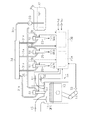
図1に示すように、内燃機関10の気筒11には吸気通路12が接続されている。内燃機関10の気筒11内には吸気通路12を介して空気が吸入される。なお、この内燃機関10としては複数(本実施形態では四つ[♯1〜♯4])の気筒11を有するディーゼル機関が採用されている。内燃機関10には、気筒11(♯1〜♯4)毎に、同気筒11内に燃料を直接噴射する直噴タイプの燃料噴射弁20が取り付けられている。この燃料噴射弁20の開弁駆動によって噴射された燃料は内燃機関10の気筒11内において圧縮加熱された吸入空気に触れて着火および燃焼する。そして内燃機関10では、気筒11内における燃料の燃焼に伴い発生するエネルギによってピストン13が押し下げられて機関出力軸としてのクランクシャフト14が強制回転するようになる。内燃機関10の気筒11において燃焼した燃焼ガスは排気として内燃機関10の排気通路15に排出される。
Hereinafter, a control device for a multi-cylinder internal combustion engine according to an embodiment of the present invention will be described.
As shown in FIG. 1, an
各燃料噴射弁20は分岐通路31aを介してコモンレール34に各別に接続されている。コモンレール34は供給通路31bを介して燃料タンク32に接続されている。この供給通路31bには、燃料を圧送する燃料ポンプ33が設けられている。本実施形態では、燃料ポンプ33による圧送によって昇圧された燃料がコモンレール34に蓄えられるとともに各燃料噴射弁20の内部に供給される。なお本実施形態では、分岐通路31aおよび供給通路31bが燃料供給通路として機能し、コモンレール34が燃料供給通路の途中に設けられる蓄圧容器として機能する。
Each
また、各燃料噴射弁20にはリターン通路35が接続されている。リターン通路35はそれぞれ燃料タンク32に接続されている。このリターン通路35を介して燃料噴射弁20の内部の燃料の一部が燃料タンク32に戻される。
A
以下、燃料噴射弁20の内部構造について説明する。
図2に示すように、燃料噴射弁20のハウジング21の内部にはニードル弁22が設けられている。このニードル弁22はハウジング21内において往復移動(同図の上下方向に移動)することの可能な状態で設けられている。ハウジング21の内部には上記ニードル弁22を噴射孔23側(同図の下方側)に常時付勢するスプリング24が設けられている。またハウジング21の内部には、上記ニードル弁22を間に挟んで一方側(同図の下方側)の位置にノズル室25が形成されるとともに、他方側(同図の上方側)の位置に圧力室26が形成されている。
Hereinafter, the internal structure of the
As shown in FIG. 2, a
ノズル室25には、その内部とハウジング21の外部とを連通する噴射孔23が形成されるとともに、導入通路27を介して上記分岐通路31a(コモンレール34)から燃料が供給されている。圧力室26には連通路28を介して上記ノズル室25および分岐通路31a(コモンレール34)が接続されている。また圧力室26は排出路30を介してリターン通路35(燃料タンク32)に接続されている。
The
上記燃料噴射弁20としては電気駆動式のものが採用されている。詳しくは、燃料噴射弁20のハウジング21の内部に駆動信号の入力によって伸縮する圧電素子(例えばピエゾ素子)が積層された圧電アクチュエータ29が設けられている。この圧電アクチュエータ29には弁体29aが取り付けられている。この弁体29aは圧力室26の内部に設けられている。そして、圧電アクチュエータ29の作動による弁体29aの移動を通じて、連通路28(ノズル室25)と排出路30(リターン通路35)とのうちの一方が選択的に圧力室26に連通されるようになっている。
As the
この燃料噴射弁20では、圧電アクチュエータ29に閉弁信号が入力されると、圧電アクチュエータ29が収縮して弁体29aが移動することによって、連通路28と圧力室26とが連通された状態になるとともに、リターン通路35と圧力室26との連通が遮断された状態になる。これにより、圧力室26内の燃料のリターン通路35(燃料タンク32)への排出が禁止された状態でノズル室25と圧力室26とが連通されるようになる。その結果、ノズル室25と圧力室26との圧力差がごく小さくなって、ニードル弁22がスプリング24の付勢力によって噴射孔23を塞ぐ位置に移動するために、このとき燃料噴射弁20は燃料が噴射されない状態(閉弁状態)になる。
In the
一方、圧電アクチュエータ29に開弁信号が入力されると、圧電アクチュエータ29が伸長して弁体29aが移動することによって、連通路28と圧力室26との連通が遮断された状態になるとともに、リターン通路35と圧力室26とが連通された状態になる。これにより、ノズル室25から圧力室26への燃料の流出が禁止された状態で圧力室26内の燃料の一部がリターン通路35を介して燃料タンク32に戻されるようになる。その結果、圧力室26内の燃料の圧力が低下して同圧力室26とノズル室25との圧力差が大きくなって、同圧力差によってニードル弁22がスプリング24の付勢力に抗して移動して噴射孔23から離れるために、このとき燃料噴射弁20は燃料が噴射される状態(開弁状態)になる。
On the other hand, when a valve opening signal is input to the
燃料噴射弁20には、上記導入通路27の内部の燃料圧力PQに応じた信号を出力する圧力センサ51が一体に取り付けられている。そのため、例えばコモンレール34(図1参照)内の燃料圧力などの燃料噴射弁20から離れた位置の燃料圧力が検出される装置と比較して、燃料噴射弁20の噴射孔23に近い部位の燃料圧力を検出することができ、燃料噴射弁20の開弁に伴う同燃料噴射弁20の内部の燃料圧力の変化を精度良く検出することができる。なお、上記圧力センサ51は各燃料噴射弁20に一つずつ、すなわち内燃機関10の気筒11毎に設けられている。
A
図1に示すように、内燃機関10には、その周辺機器として、運転状態を検出するための各種センサが設けられている。それらセンサとしては、上記圧力センサ51の他、例えば吸気通路12を通過する空気の量(通路空気量GA)を検出するための吸気量センサ52や、クランクシャフト14の回転に伴いパルス状の信号を出力するクランクセンサ53、カムシャフトの回転に伴いパルス状の信号を出力するカムセンサ54が設けられている。その他、アクセル操作部材(例えばアクセルペダル)の操作量(アクセル操作量ACC)を検出するためのアクセルセンサ55なども設けられている。本実施形態では、クランクセンサ53の検出信号とカムセンサ54の検出信号との関係に基づいて同クランクシャフト14の回転位相(クランク角)の変化に伴って変化する信号(以下、クランク信号)が形成される。そして、このクランク信号に基づいて、そのときどきのクランク角やクランクシャフト14の回転速度(機関回転速度NE)、燃料噴射を実行する気筒11などが特定される。
As shown in FIG. 1, the
また内燃機関10の周辺機器としては、中央処理装置を備えて構成された二つの電子制御ユニット40A,40Bなども設けられている。これら電子制御ユニット40A,40Bは各種センサの出力信号を取り込むとともにそれら出力信号をもとに各種の演算を行い、内燃機関10の運転にかかる各種制御を実行する。なお電子制御ユニット40Bは燃料噴射弁20の作動制御(燃料噴射制御)に関する演算処理を実行する。また電子制御ユニット40Aは主に、それ以外の機関制御にかかる演算処理を実行する。
Further, as the peripheral device of the
上記燃料噴射制御は基本的には次のように実行される。すなわち先ず、通路空気量GAや機関回転速度NE、アクセル操作量ACCなどの機関運転状態に基づいて、噴射パターンが選択されるとともに同噴射パターンの各噴射についての各種制御目標値が算出される。そして、それら制御目標値に応じたかたちで駆動信号が出力され、この駆動信号の入力に基づき各燃料噴射弁20が各別に開弁駆動される。これにより、そのときどきの機関運転状態に適した噴射パターンで同機関運転状態に見合う量の燃料が各燃料噴射弁20から噴射されて内燃機関10の各気筒11内に供給されるようになるために、機関運転状態に見合う回転トルクがクランクシャフト14に付与されるようになる。
The fuel injection control is basically executed as follows. That is, first, an injection pattern is selected and various control target values for each injection of the injection pattern are calculated based on the engine operation state such as the passage air amount GA, the engine speed NE, and the accelerator operation amount ACC. Then, a drive signal is output in accordance with these control target values, and each
なお本実施形態では、メイン噴射やパイロット噴射、アフター噴射などを組み合わせた複数の噴射パターンが予め設定されて電子制御ユニット40Bに記憶されており、燃料噴射制御の実行に際してはそれら噴射パターンのうちの一つが選択される。また各種の制御目標値としては、メイン噴射やパイロット噴射、アフター噴射などといった各噴射の燃料噴射量についての制御目標値、メイン噴射の噴射時期やパイロットインターバルなどといった各種噴射の燃料噴射時期についての制御目標値が算出される。さらに本実施形態では、上記機関運転状態と同運転状態に適した各制御目標値との関係や、上記機関運転状態と同運転状態に適した噴射パターンとの関係が実験やシミュレーションの結果に基づき予め求められて電子制御ユニット40Bにそれぞれ記憶されている。そして、電子制御ユニット40Bはそのときどきの機関運転状態に基づいて上記関係から各種の制御目標値や噴射パターンを各別に設定する。
In the present embodiment, a plurality of injection patterns that combine main injection, pilot injection, after-injection, etc. are preset and stored in the
また本実施形態では、メイン噴射の実行に際して、メイン噴射における燃料噴射量の制御目標値(目標メイン噴射時間)および燃料噴射時期の制御目標値(目標メイン噴射時期)に基づく燃料噴射の実行に合わせて、圧力センサ51により検出される燃料圧力PQに基づいて燃料噴射弁20の開弁期間や燃料噴射量を補正する補正制御が実行される。この補正制御は、詳しくは、以下のように実行される。
In the present embodiment, the main injection is performed in accordance with the execution of the fuel injection based on the control target value (target main injection time) of the fuel injection amount in the main injection and the control target value (target main injection time) of the fuel injection timing. Thus, correction control for correcting the valve opening period and the fuel injection amount of the
すなわち先ず、上記目標メイン噴射時間および目標メイン噴射時期に基づいて燃料噴射率についての基本時間波形が算出される。なお本実施形態では、目標メイン噴射時間および目標メイン噴射時期により定まる機関運転領域と同運転領域に適した基本時間波形との関係が実験やシミュレーションの結果に基づき予め求められて電子制御ユニット40Bのメモリ(図示略)に記憶されている。そして、電子制御ユニット40Bはそのときどきの機関運転領域に基づいて上記関係から基本時間波形を算出する。
That is, first, a basic time waveform for the fuel injection rate is calculated based on the target main injection time and the target main injection timing. In the present embodiment, the relationship between the engine operation region determined by the target main injection time and the target main injection timing and the basic time waveform suitable for the operation region is obtained in advance based on the results of experiments and simulations, and the
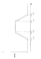
図3は、上記基本時間波形の一例を示している。
同図3の実線に示すように、基本時間波形としては、燃料噴射弁20の開弁動作が開始される時期(開弁動作開始時期Tos)、燃料噴射率が最大になる時期(最大噴射率到達時期Toe)、閉弁動作が開始される時期(閉弁動作開始時期Tcs)、および閉弁動作が完了する時期(閉弁動作完了時期Tce)により規定される台形の波形が設定される。
FIG. 3 shows an example of the basic time waveform.
As shown by the solid line in FIG. 3, the basic time waveform includes a timing at which the valve opening operation of the
その一方で、圧力センサ51により検出される燃料圧力PQに基づいて、実際の燃料噴射率の時間波形(検出時間波形)が形成される。具体的には先ず、燃料圧力PQの推移に基づいて燃料噴射弁20の開弁動作開始時期Tosr、最大噴射率到達時期Toer、閉弁動作開始時期Tcsr、および閉弁動作完了時期Tcerがそれぞれ特定される。燃料噴射弁20の内部(詳しくは、ノズル室25)の燃料圧力は、同燃料噴射弁20が開弁駆動されるとリフト量の増加に伴って低下し、その後において閉弁駆動されるとリフト量の減少に伴って上昇するようになる。本実施形態では、そうした燃料噴射弁20内部の燃料圧力(詳しくは、燃料圧力PQ)の推移をもとに、上記開弁動作開始時期Tosr、最大噴射率到達時期Toer、閉弁動作開始時期Tcsr、および閉弁動作完了時期Tcerが精度よく特定される。
On the other hand, based on the fuel pressure PQ detected by the
なお本実施形態では、燃料圧力PQの変化速度(詳しくは、燃料圧力PQの一階微分値)が算出されるとともに、同変化速度が上記開弁動作開始時期Tosr、最大噴射率到達時期Toer、閉弁動作開始時期Tcsr、および閉弁動作完了時期Tcerの特定に用いられる。これにより、燃料噴射弁20の開弁動作の開始に伴って燃料圧力PQが急低下を開始する時期や、開弁動作開始後に燃料圧力PQの変化速度が下降から上昇に転じる時期、閉弁動作の開始に伴って燃料圧力PQが急上昇を開始する時期、閉弁動作開始後に燃料圧力PQの変化速度が上昇から下降に転じる時期などを容易に特定することが可能になる。そのため、燃料圧力PQに基づく燃料噴射弁20の動作態様の把握が適正に行われて、上記開弁動作開始時期Tosr、最大噴射率到達時期Toer、閉弁動作開始時期Tcsr、および閉弁動作完了時期Tcerの特定が精度よく行われるようになる。そして、図3中に一点鎖線で示すように、それら特定した時期によって実際の燃料噴射率の時間波形(検出時間波形)が形成される。
In this embodiment, the change speed of the fuel pressure PQ (specifically, the first derivative value of the fuel pressure PQ) is calculated, and the change speed is calculated based on the valve opening operation start timing Tosr, the maximum injection rate arrival time Toer, It is used to specify the valve closing operation start timing Tcsr and the valve closing operation completion timing Tcer. As a result, the timing at which the fuel pressure PQ starts to suddenly drop with the start of the valve opening operation of the
本実施形態の補正制御では、この検出時間波形と前記基本時間波形とが比較されるとともに、それら検出時間波形および前記基本時間波形の差を小さく抑えることの可能な値が噴射時期についての補正項K1および噴射時間についての補正項K2としてそれぞれ算出されて電子制御ユニット40Bに記憶される。
In the correction control of the present embodiment, the detected time waveform and the basic time waveform are compared, and a value that can suppress the difference between the detected time waveform and the basic time waveform is a correction term for the injection timing. K1 and the correction term K2 for the injection time are respectively calculated and stored in the
詳しくは、基本時間波形の開弁動作開始時期Tosと検出時間波形の開弁動作開始時期Tosrとの差を補償することの可能な値が補正項K1として算出されるとともに電子制御ユニット40Bに記憶される。そして、メイン噴射の実行に際しては、前記目標メイン噴射時期を補正項K1によって補正した値が最終的な目標メイン噴射時期として設定される。また、基本時間波形の面積と検出時間波形の面積との差を補償することの可能な値が上記補正項K2として算出されるとともに電子制御ユニット40Bに記憶される。そして、メイン噴射の実行に際しては、前記目標メイン噴射時間を補正項K2によって補正した値が最終的な目標メイン噴射時間として設定される。
Specifically, a value capable of compensating for the difference between the valve opening operation start timing Tos of the basic time waveform and the valve opening operation start timing Tosr of the detection time waveform is calculated as the correction term K1 and stored in the
なお上記補正制御は、例えば内燃機関10の気筒11[♯1]に設けられた圧力センサ51の検出信号に基づき同気筒11[♯1]の燃料噴射弁20についての上記各補正項K1,K2の学習を実行するなどといったように、内燃機関10の気筒11(♯1〜♯4)毎にそれぞれ対応する圧力センサ51の出力信号に基づき実行される。
The correction control is performed based on the detection signal of the
以下、電子制御ユニット40A,40Bから各燃料噴射弁20に同燃料噴射弁20を開閉動作させるための作動信号の出力経路について詳しく説明する。
図4に示すように、電子制御ユニット40Bは二つの中央処理装置(メインCPU41およびサブCPU42)を内蔵している。この電子制御ユニット40Bは、図中に白抜きの矢印で示すように、メインCPU41とサブCPU42との間でデータ転送が可能な構造になっている。
Hereinafter, the output path of the operation signal for causing the
As shown in FIG. 4, the
またメインCPU41と電子制御ユニット40Aとの間には四本の信号線路SA[♯1],SA[♯2],SA[♯3],SA[♯4]が設けられている。これら信号線路SA[♯1]〜SA[♯4]を介して各燃料噴射弁20(詳しくは、電子制御ユニット40A)に対して上記作動信号が各別に出力される。
Four signal lines SA [# 1], SA [# 2], SA [# 3], and SA [# 4] are provided between the
これら信号線路SA[♯1]〜SA[♯4]はそれぞれ途中で分岐されており、それら分岐された信号線路SB[♯1],SB[♯2],SB[♯3],SB[♯4]はそれぞれサブCPU42に接続されている。これら信号線路SB[♯1]〜SB[♯4]を介して各作動信号がサブCPU42に各別に入力される。
These signal lines SA [# 1] to SA [# 4] are branched on the way, and the branched signal lines SB [# 1], SB [# 2], SB [# 3], SB [# 4] are connected to the
さらに電子制御ユニット40Aと各燃料噴射弁20との間には四本の信号線路SC[♯1],SC[♯2],SC[♯3],SC[♯4]が設けられている。これら信号線路SC[♯1]〜SC[♯4]を介して各燃料噴射弁20に対して前記駆動信号が各別に出力される。
Further, four signal lines SC [# 1], SC [# 2], SC [# 3], SC [# 4] are provided between the
また各燃料噴射弁20に設けられた圧力センサ51と電子制御ユニット40BのサブCPU42との間には四本の信号線路SD[♯1],SD[♯2],SD[♯3],SD[♯4]が設けられている。これら信号線路SD[♯1]〜SD[♯4]を介して各圧力センサ51の検出信号がサブCPU42に各別に入力される。
Four signal lines SD [# 1], SD [# 2], SD [# 3], SD are provided between the
上記メインCPU41は以下の[機能1]〜[機能5]に記載する機能を有している。
[機能1]クランクセンサ53の検出信号とカムセンサ54の検出信号との関係に基づいてクランク角の変化に伴い変化するクランク信号を形成し、同クランク信号に基づいて燃焼行程を迎える気筒11の特定(いわゆる気筒判別)を行う。
[機能2]メインCPU41とサブCPU42との間におけるデータ転送を通じてサブCPU42から検出時間波形を受信するとともに同検出時間波形を気筒11毎に記憶する。
[機能3]機関運転状態に基づいて燃料噴射制御についての各種の制御目標値を算出する。
[機能4]サブCPU42から受信した検出時間波形に基づく補正制御を実行する。
[機能5]燃料噴射制御についての各種の制御目標値に基づいて各燃料噴射弁20を開閉動作させるための駆動パルス(燃料噴射弁20の開弁期間を規定するパルス)を含む作動信号を形成するとともに、それら作動信号を上記信号経路SA[♯1]〜SA[♯4]を介して電子制御ユニット40Aに各別に出力する。
The
[Function 1] Based on the relationship between the detection signal of the
[Function 2] The detection time waveform is received from the
[Function 3] Various control target values for the fuel injection control are calculated based on the engine operating state.
[Function 4] The correction control based on the detection time waveform received from the
[Function 5] Forming an operation signal including a drive pulse (a pulse defining a valve opening period of the fuel injection valve 20) for opening and closing each
また上記サブCPU42は以下の[機能6]〜[機能10]に記載する機能を有している。
[機能6]燃料噴射弁20の開弁時(具体的には、圧縮行程中期から燃焼行程中期までの期間)において同燃料噴射弁20に対応する圧力センサ51の検出信号に基づき燃料圧力PQを検出するとともに、その検出値を気筒11毎に記憶する。
[機能7]燃料噴射弁20の閉弁時(具体的には、吸気行程中期から圧縮行程中期までの期間)において同燃料噴射弁20に対応する圧力センサ51の検出信号に基づき燃料圧力PQを検出するとともに、その検出値を気筒11毎に記憶する。なお本実施形態では、このようにして検出された燃料圧力PQの平均値が算出されるとともに、同平均値が、検出時間波形の形成に際して燃料噴射弁20の開閉動作に伴う燃料圧力PQの変化の基準となる圧力として用いられる。
[機能8]燃料噴射弁20の開弁時に検出した燃料圧力PQと閉弁時に検出した燃料圧力PQとに基づいて同燃料噴射弁20の開閉動作に伴う燃料圧力PQの変動波形(前記検出時間波形)を形成するとともに気筒11毎に記憶する。
[機能9]検出時間波形を、データ転送を通じて適宜のタイミングでメインCPU41に出力する。
[機能10]信号線路SB[♯1]〜SB[♯4]を介して入力される各作動信号を監視するなどして、メインCPU41の作動状態を監視する。
The
[Function 6] When the
[Function 7] When the
[Function 8] Based on the fuel pressure PQ detected when the
[Function 9] The detection time waveform is output to the
[Function 10] The operation state of the
また電子制御ユニット40Aは以下の[機能11]に記載する機能を有している。
[機能11]電子制御ユニット40BのメインCPU41から入力される各作動信号に応じて、燃料噴射弁20を開弁させるための駆動信号(開弁信号)と閉弁させるための駆動信号(閉弁信号)とを信号線路SB[♯1]〜SB[♯4]を介して適宜のタイミングで出力する。具体的には先ず、電子制御ユニット40Aが開弁信号を出力してから実際に燃料噴射弁20の開弁動作が開始されるまでの時間(開弁遅れ時間TA)と電子制御ユニット40Bから入力される作動信号(詳しくは、その駆動パルス)とに基づいて開弁信号の出力タイミングが設定される。また電子制御ユニット40Aから閉弁信号が出力されてから実際に燃料噴射弁20の閉弁動作が開始されるまでの時間(閉弁遅れ時間TB)と電子制御ユニット40Bから入力される作動信号とに基づいて閉弁信号の出力タイミングが設定される。そして電子制御ユニット40Aは、それら出力タイミングにおいて各燃料噴射弁20に開弁信号や閉弁信号を出力する。
The
[Function 11] In response to each operation signal input from the
ここで本実施形態では、電子制御ユニット40Bに設けられたメインCPU41およびサブCPU42が共に、直後に燃料噴射が実行される気筒11を特定するとともに同気筒11についての演算処理(駆動パルスの出力、あるいは燃料圧力PQの検出)を実行する。
Here, in this embodiment, both the
そのため本実施形態の装置では、気筒判別のための演算処理をメインCPU41に実行させることに加えてサブCPU42にも実行させることにより、メインCPU41による駆動パルスの出力とサブCPU42による燃料圧力PQの検出とをそれぞれ適切なタイミングで実行することが可能になる。ただし気筒判別のための演算処理は、単にクランクセンサ53やカムセンサ54の検出信号を取り込むだけの処理ではなく、クランクセンサ53の検出信号とカムセンサ54の検出信号との関係に基づいてクランク角を特定するといった煩雑な処理を含むため、その演算負荷が大きくなり易い。そのため、そうした気筒判別にかかる演算処理をメインCPU41とサブCPU42との双方において実行することは効率が悪く、望ましくない。
Therefore, in the apparatus according to the present embodiment, in addition to causing the
この点をふまえて本実施形態では、メインCPU41から駆動パルスを出力するのに先立ち、同駆動パルスより前の予め定められた時期(本実施形態では、圧縮行程中のBTDC90°)において所定のパルス幅のパルス状の信号(以下、ダミーパルス)を出力するようにしている。これら駆動パルスとダミーパルスとからなる作動信号は気筒11毎に設定される。そのため各作動信号は信号線路SA[♯1]〜SA[♯4]を介して電子制御ユニット40Aに各別に入力されることに加えて、信号線路SB[♯1]〜SB[♯4]を介して電子制御ユニット40BのサブCPU42にも各別に入力される。なお、上記ダミーパルスとしては、燃料噴射弁20の無効噴射時間に相当するパルス幅より短いパルス幅、すなわち燃料噴射弁20を開弁させないパルス幅の信号が出力される。
In view of this point, in the present embodiment, prior to outputting the drive pulse from the
そして電子制御ユニット40BのサブCPU42はダミーパルスの入力に基づいて、直後に燃料噴射が実行される気筒11を特定する。そして、その特定した気筒11に対応する圧力センサ51の検出信号に基づく燃料圧力PQの検出と、特定した気筒11の次に燃料噴射が実行される気筒11に対応する圧力センサ51の検出信号に基づく燃料圧力PQの検出とを実行する。
Then, the
以下、図5に示すタイムチャートを参照して、そうしたサブCPU42による燃料圧力PQの検出態様を具体的に説明する。
図5に示すように、時刻t1において、電子制御ユニット40BのサブCPU42に気筒11[♯1]に対応する信号線路SB[♯1]を介してダミーパルスが入力されると、その直後において燃料噴射が実行される気筒11[♯1]が特定される。そして、その後の時刻t1〜t2において、気筒11[♯1]に対応する圧力センサ51の検出信号に基づく燃料圧力PQの検出と同気筒11[♯1]の次に燃料噴射が実行される気筒11[♯3]に対応する圧力センサ51の検出信号に基づく燃料圧力PQの検出とが実行される。
Hereinafter, the detection mode of the fuel pressure PQ by the
As shown in FIG. 5, at time t1, when a dummy pulse is input to the
同様に、サブCPU42に気筒11[♯3]に対応する信号線路SB[♯3]を介してダミーパルスが入力されると(時刻t2)、直後に燃料噴射が実行される気筒11[♯3]についての燃料圧力PQの検出と、同気筒11[♯3]の次に燃料噴射が実行される気筒11[♯4]についての燃料圧力PQの検出とが実行される(時刻t2〜t3)。
Similarly, when a dummy pulse is input to the
また、サブCPU42に気筒11[♯4]に対応する信号線路SB[♯4]を介してダミーパルスが入力されると(時刻t3)、直後に燃料噴射が実行される気筒11[♯4]についての燃料圧力PQの検出と、同気筒11[♯4]の次に燃料噴射が実行される気筒11[♯2]についての燃料圧力PQの検出とが実行される(時刻t3〜t4)。
In addition, when a dummy pulse is input to the
さらに、サブCPU42に気筒11[♯2]に対応する信号線路SB[♯2]を介してダミーパルスが入力されると(時刻t4)、直後に燃料噴射が実行される気筒11[♯2]についての燃料圧力PQの検出と、同気筒11[♯2]の次に燃料噴射が実行される気筒11[♯1]についての燃料圧力PQの検出とが実行される(時刻t4〜t5)。
Further, when a dummy pulse is input to the
以下、このようにして駆動パルスとダミーパルスとを含む作動信号を電子制御ユニット40BのメインCPU41からサブCPU42と電子制御ユニット40Aとにそれぞれ出力することによる作用について説明する。
Hereinafter, the operation by outputting the operation signal including the driving pulse and the dummy pulse from the
本実施形態の装置では、メインCPU41によって気筒判別を行う演算処理が実行されるとともに、その結果に基づいて燃料噴射弁20を開弁駆動するための駆動パルスが信号線路SA[♯1]〜SA[♯4]を介して、気筒11毎に設けられた燃料噴射弁20のいずれかに対して選択的に出力される。これにより、各燃料噴射弁20に対してそれぞれ適切なタイミングで駆動パルス(詳しくは、電子制御ユニット40Aからの駆動信号)が出力されるようになる。
In the apparatus according to the present embodiment, the
またメインCPU41から駆動パルスを出力することに加えて同駆動パルスより前の予め定められた時期においてダミーパルスが出力されており、このダミーパルスが信号線路SB[♯1]〜SB[♯4]を介してサブCPU42に入力されている。そのため、このダミーパルスが信号線路SB[♯1]〜SB[♯4]のいずれかを介してサブCPU42に入力されたことをもって、直後に開弁駆動される燃料噴射弁20に対応する気筒11を同サブCPU42に把握させることができる。これにより、直後に燃料噴射が実行される気筒11に対応する圧力センサ51の検出信号に基づく燃料圧力PQの検出と、同気筒11の次に燃料噴射が実行される気筒11に対応する圧力センサ51の検出信号に基づく燃料圧力PQの検出とを実行することができる。
In addition to outputting a drive pulse from the
このように本実施形態では、メインCPU41とサブCPU42とにおいて共に、直後に燃料噴射が実行される気筒11の特定と同気筒11についての演算処理(駆動パルスの出力、あるいは燃料圧力PQの検出)とが実行されるものの、メインCPU41による気筒判別の結果をもとにサブCPU42による演算処理を適正に行うことができる。したがって、メインCPU41およびサブCPU42の双方において気筒判別を行うための演算処理を実行する装置と比較して演算負荷を小さく抑えつつ、それらメインCPU41およびサブCPU42における気筒11毎の演算処理をそれぞれ適切なタイミングで実行することができるようになる。
As described above, in the present embodiment, both the
なお本実施形態では、ダミーパルスが信号線路SA[♯1]〜SA[♯4]を介して電子制御ユニット40Aに入力されるとはいえ、ダミーパルスのパルス幅が燃料噴射弁20を開弁させない長さに設定されているため、ダミーパルスが入力されたことをもって燃料噴射弁20が不要に開弁駆動されることはない。
In this embodiment, although the dummy pulse is input to the
また本実施形態では、サブCPU42によってメインCPU41の作動状態を監視する前記[機能10]を実現するために、メインCPU41から出力される各作動信号が信号線路SB[♯1]〜SB[♯4]を介してサブCPU42に入力されている。
In the present embodiment, in order to realize the [Function 10] in which the
本実施形態では、そうした各作動信号の入出力のための構成(具体的には、信号線路SB[♯1]〜SB[♯4]や回路、プログラムなど)を利用して、気筒判別のための信号(ダミーパルス)がメインCPU41からサブCPU42に出力される。
In the present embodiment, the configuration for input / output of each operation signal (specifically, signal lines SB [# 1] to SB [# 4], circuits, programs, etc.) is used for cylinder discrimination. The signal (dummy pulse) is output from the
そのため、専用の構成を別途設けて気筒判別のための信号の入出力を行う装置と比較して、同信号の入出力のためのプログラムや電子制御ユニット40Bの構造の簡素化を図ることができる。また、前記[機能10]の実現のためにメインCPU41から出力される各作動信号が信号線路SB[♯1]〜SB[♯4]を介してサブCPU42に入力される装置に本実施形態にかかる装置を適用する場合には、既存の構成を利用することができるため、新たな構成の追加を極力抑えることができる。
Therefore, as compared with a device that inputs and outputs a signal for cylinder discrimination by separately providing a dedicated configuration, it is possible to simplify the program for inputting and outputting the signal and the structure of the
以下、ダミーパルスを出力する処理や同ダミーパルスの入力に基づいて燃料圧力PQの検出を行う処理の具体的な実行手順について説明する。
ここでは先ず、図6に示すフローチャートを参照して、ダミーパルスを含む作動信号を出力するべくメインCPU41により実行される処理(メインCPU処理)の実行手順を説明する。このフローチャートに示される一連の処理は所定周期毎の割り込み処理として実行される。
Hereinafter, a specific execution procedure of the process of outputting the dummy pulse and the process of detecting the fuel pressure PQ based on the input of the dummy pulse will be described.
First, an execution procedure of a process (main CPU process) executed by the
図6に示すように、この処理では、クランク角が検出基準角度になると(ステップS11:YES)、直後に燃料噴射が実行される気筒11に対応する信号線路(SA[♯1]〜SA[♯4]のいずれか)を介してダミーパルスが出力される(ステップS12)。上記検出基準角度としては、いずれかの気筒11が圧縮行程中におけるBTDC90°になる四つの角度(Cd[♯1],Cd[♯2],Cd[♯3],Cd[♯4])が予め設定されている。本実施形態では、それら検出基準角度Cd[♯1]〜Cd[♯4]として、クランク角で180°間隔になる四つの角度が設定される。そのため本処理では、いずれかの気筒11が圧縮行程中におけるBTDC90°になる度に、同気筒11に対応する信号線路(SA[♯1]〜SA[♯4]のいずれか)を介してダミーパルスが出力されるようになる。
As shown in FIG. 6, in this process, when the crank angle becomes the detection reference angle (step S11: YES), the signal line (SA [# 1] to SA [SA [#] corresponding to the
また、クランク角が噴射基準角度になると(ステップS13:YES)、直後に燃料噴射が実行される気筒11についての前回の燃焼サイクルにおける検出時間波形に基づいて同気筒11のメイン噴射についての前記補正制御が実行される(ステップS14)。なお、この検出時間波形としてはサブCPU42から予め受信して気筒11毎に記憶されている値が用いられる。
Further, when the crank angle becomes the injection reference angle (step S13: YES), the correction for the main injection of the
上記噴射基準角度としても、上記検出基準角度と同様に、クランク角で180°間隔になる四つの角度(Ci[♯1],Ci[♯2],Ci[♯3],Ci[♯4])が予め設定されている。ただし、これら噴射基準角度としてはそれぞれ、検出基準角度(詳しくは、直後に燃料噴射が実行される気筒11の圧縮行程中におけるBTDC90°)から同気筒11に対応する燃料噴射弁20への駆動パルスの出力が開始される可能性のあるクランク角までの範囲における所定角度が設定される。
As the injection reference angle, similarly to the detection reference angle, four angles (Ci [# 1], Ci [# 2], Ci [# 3], Ci [# 4], which are 180 ° apart in crank angle, are used. ) Is preset. However, each of these injection reference angles is a drive reference pulse from the detection reference angle (specifically, BTDC 90 ° during the compression stroke of the
そのため本処理では、燃料噴射が実行される気筒順序(気筒11[♯1]→気筒11[♯3]→気筒11[♯4]→気筒11[♯2])で、180°クランク角毎のタイミングにおいて、いずれかの気筒11についての補正制御が選択的に実行される。言い換えれば、一回の燃焼サイクルにおいて前回の燃焼サイクルにおける検出時間波形に基づく補正制御が各気筒11について一回ずつ実行される。
Therefore, in this process, the cylinder order in which the fuel injection is executed (cylinder 11 [# 1] → cylinder 11 [# 3] → cylinder 11 [# 4] → cylinder 11 [# 2]) is performed every 180 ° crank angle. At the timing, the correction control for any one of the
さらに本処理では、ステップS14の処理を通じて設定されたメイン噴射についての制御目標値や別途の処理を通じて設定されたメイン噴射以外の噴射についての制御目標値に基づいて駆動パルスの出力タイミングが設定される。そして、その出力タイミングにおいて、駆動パルスの出力対象である気筒11に対応する信号線路(SA[♯1]〜SA[♯4]のいずれか)を介して同駆動パルスが出力される(ステップS15)。
Furthermore, in this process, the output timing of the drive pulse is set based on the control target value for the main injection set through the process of step S14 and the control target value for the injection other than the main injection set through a separate process. . Then, at the output timing, the drive pulse is output via a signal line (any one of SA [# 1] to SA [# 4]) corresponding to the
次に、ダミーパルスの入力に基づき燃料圧力PQを検出するべくサブCPU42により実行される処理(サブCPU処理)を図7に示すフローチャートを参照して説明する。このフローチャートに示される一連の処理は所定周期毎の割り込み処理として実行される。
Next, processing (sub CPU processing) executed by the
図7に示すように、この処理では先ず、信号線路SB[♯1]〜SB[♯4]のいずれかを介してダミーパルスが入力されたか否かが判断される(ステップS21)。
そして、ダミーパルスが入力されたと判断される場合には(ステップS21:YES)、ダミーパルスが入力された信号線路(SB[♯1]〜SB[♯4]のいずれか)に基づいて直後に燃料噴射が実行される気筒11が特定されるとともに、同気筒11の気筒番号が今回パルス気筒Nとして記憶される(ステップS22)。例えば、信号線路SB[♯1]を介してダミーパルスが入力された場合には、気筒11[♯1]の気筒番号「1」が今回パルス気筒Nとして記憶される。なおダミーパルスが入力されない場合には(ステップS21:NO)、今回パルス気筒Nが変更されない(ステップS22の処理がジャンプされる)。また本実施形態では、運転スイッチの操作によって内燃機関10が始動される際に、今回パルス気筒Nの初期値として、いずれかの気筒番号(1〜4)以外の所定値(例えば「0」)が設定される。
As shown in FIG. 7, in this process, first, it is determined whether or not a dummy pulse is input via any of the signal lines SB [# 1] to SB [# 4] (step S21).
If it is determined that a dummy pulse has been input (step S21: YES), immediately after based on the signal line (any one of SB [# 1] to SB [# 4]) to which the dummy pulse is input. The
その後、燃料圧力PQの検出対象となる気筒11を切り替えるタイミングであるか否かが判断される(ステップS23)。ここでは、今回パルス気筒Nと後述する前回パルス気筒[N−1]とが一致していないことをもって、検出対象となる気筒11を切り替えるタイミングであると判断される。そして、検出対象の気筒11を切り替えるタイミングであると判断される場合には(ステップS23:YES)、共に後述するステップS24の処理とステップS25の処理とが実行された後、今回パルス気筒Nに記憶されている値が前回パルス気筒[N−1]として記憶される(ステップS26)。なお本実施形態では、運転スイッチの操作によって内燃機関10が始動される際に、前回パルス気筒[N−1]の初期値として、いずれかの気筒番号(1〜4)以外の所定値(例えば「0」)が設定される。
Thereafter, it is determined whether it is time to switch the
こうしたことから本処理では、ダミーパルスが入力されて今回パルス気筒Nが更新された直後においてのみ(ステップS21:YES)、今回パルス気筒Nと前回パルス気筒[N−1]とが一致しなくなる。したがって、ステップS24の処理およびステップS25の処理がダミーパルスの入力の度に一回のみ実行される。 For this reason, in this process, the current pulse cylinder N and the previous pulse cylinder [N-1] do not match only immediately after the dummy pulse is input and the current pulse cylinder N is updated (step S21: YES). Therefore, the process of step S24 and the process of step S25 are executed only once each time a dummy pulse is input.
ステップS24の処理は次のように実行される。すなわち先ず、今回パルス気筒Nに基づいて、直後に燃料噴射が実行される気筒11の次に燃料噴射が実行される気筒11(次回パルス気筒[N+1])が特定される。本実施形態では、気筒順序により定まる今回パルス気筒Nと次回パルス気筒[N+1]との関係(例えばN=1なら[N+1]=3、N=3なら[N+1]=4など)がサブCPU42のメモリに予め記憶されており、同対応関係に基づいて今回パルス気筒Nから次回パルス気筒[N+1]が特定される。そして、今回パルス気筒Nに対応する圧力センサ51に基づいて燃料圧力PQ(すなわち、燃料噴射の実行時における燃料圧力PQ)を検出する処理の実行と、次回パルス気筒[N+1]に対応する圧力センサ51に基づいて燃料圧力PQ(すなわち、燃料噴射の非実行時における燃料圧力PQ)を検出する処理の実行とがそれぞれ開始される。また、それら検出された燃料圧力PQはサブCPU42のメモリに各別に記憶される。なお、このとき今回パルス気筒Nおよび次回パルス気筒[N+1]に対応する圧力センサ51以外の圧力センサ51による燃料圧力PQの検出および記憶は実行されない。
The process of step S24 is performed as follows. That is, first, based on the current pulse cylinder N, the cylinder 11 (next pulse cylinder [N + 1]) in which fuel injection is performed next to the
また、ステップS25の処理は次のように実行される。先のステップS23の処理において検出対象の気筒11が切り替わったと判断される直前において検出されて記憶されていた各燃料圧力PQ、すなわち直後に燃料噴射が実行される気筒11の燃料噴射の非実行時における燃料圧力PQと直前に燃料噴射が実行された気筒11の燃料噴射の実行時における燃料圧力PQとに基づいて検出時間波形を形成する処理の実行が開始される。なお、この検出時間波形の形成が完了すると、同波形が直前に燃料噴射が実行された気筒11に対応する検出時間波形としてメインCPU41に転送される。
Moreover, the process of step S25 is performed as follows. Each fuel pressure PQ detected and stored immediately before it is determined that the
このように本処理では、ダミーパルスが入力される度に、燃料圧力PQの検出対象となる気筒11の切り替えと、その切り替え前において検出されていた燃料圧力PQに基づく検出時間波形の形成および同波形のメインCPU41への転送とが実行される。
As described above, in this process, every time a dummy pulse is input, the
以上説明したように、本実施形態によれば、以下に記載する効果が得られる。
(1)メインCPU41によって気筒判別を行う演算処理を実行するとともに、その結果に基づいて駆動パルスを気筒11毎に設けられた燃料噴射弁20のいずれかに対して選択的に出力するようにした。またメインCPU41から駆動パルスを出力することに加えて同駆動パルスより前の予め定められた時期においてダミーパルスを出力するとともに、このダミーパルスをサブCPU42に入力させるようにした。そのため、メインCPU41とサブCPU42とにおいて共に、直後に燃料噴射が実行される気筒11の特定と同気筒11についての演算処理(駆動パルスの出力、あるいは燃料圧力PQの検出)とが実行されるものの、メインCPU41による気筒判別の結果をもとにサブCPU42による演算処理を適正に行うことができる。したがって、メインCPU41およびサブCPU42の双方において気筒判別を行うための演算処理を実行する装置と比較して演算負荷を小さく抑えつつ、それらメインCPU41およびサブCPU42における気筒11毎の演算処理をそれぞれ適切なタイミングで実行することができるようになる。
As described above, according to the present embodiment, the following effects can be obtained.
(1) The
(2)サブCPU42により、ダミーパルスの入力に基づき直後に燃料噴射が実行される気筒11を特定する処理と、同気筒11に対応する圧力センサ51によって燃料圧力PQを検出する処理とを実行するようにした。そのため、燃料噴射の実行時における燃料圧力PQの検出を、気筒11毎に、燃料噴射弁20の開弁駆動に合わせて適切なタイミングで実行することができる。
(2) The
(3)直後に燃料噴射が実行される気筒11に対応する圧力センサ51によって燃料圧力PQを検出する処理を実行することに合わせて、さらにその次に燃料噴射が実行される気筒11に対応する圧力センサ51によって燃料圧力PQを検出する処理を実行するようにした。そのため、ダミーパルスが入力されたことにより、燃料噴射の実行時における燃料圧力PQを検出することに加えて、燃料噴射の非実行時における燃料圧力PQ、言い換えれば検出時間波形の形成に際して燃料噴射弁20の開閉動作に伴う燃料圧力PQの変化の基準となる圧力を検出することができる。そして、それら燃料圧力PQに基づいて検出時間波形を精度よく形成することができる。
(3) Immediately after the process of detecting the fuel pressure PQ by the
なお、上記実施形態は、以下のように変更して実施してもよい。
・ダミーパルスが入力された直後に燃料圧力PQの検出の実行を開始することに限らず、ダミーパルスが入力されてから若干の時間をおいた後に燃料圧力PQの検出の実行を開始してもよい。
The above embodiment may be modified as follows.
The detection of the fuel pressure PQ is not limited to start immediately after the dummy pulse is input, but the detection of the fuel pressure PQ is started after some time has elapsed after the dummy pulse is input. Good.
・上記実施形態では、サブCPU42によって気筒11毎に検出されて記憶されている燃料圧力PQのうちの、異なる気筒11についての二つの燃料圧力PQ(具体的には、燃料噴射の実行時における燃料圧力PQと燃料噴射の非実行時における燃料圧力PQ)に基づいて検出時間波形を形成するようにした。これに代えて、同一の気筒11についての燃料噴射の実行時における燃料圧力PQと燃料噴射の非実行時における燃料圧力PQとに基づいて検出時間波形を形成してもよい。
In the above embodiment, two fuel pressures PQ for
・燃料噴射の実行時における燃料圧力PQを、直後に燃料噴射が実行される気筒11の次に燃料噴射が実行される気筒11に対応する圧力センサ51によって検出することに限らず、次に燃料噴射が実行される気筒11のさらに次(二回後)に燃料噴射が実行される気筒11に対応する圧力センサ51により検出してもよい。また燃料噴射の実行時における燃料圧力PQを、三回後に燃料噴射が実行される気筒11に対応する圧力センサ51によって検出することもできる。
The fuel pressure PQ at the time of executing the fuel injection is not limited to being detected by the
・ダミーパルスの出力時期は、圧縮行程中のBTDC90°に限らず、任意に変更することができる。なお、ダミーパルスの出力時期を早くすると、その分だけダミーパルスがサブCPU42に入力されてから燃料圧力PQの検出対象となる気筒11を切り替えるタイミングまでの期間が長くなるために、その切り替えのタイミングや燃料圧力PQの検出期間の設定精度の低下を招き易くなる。また、ダミーパルスの出力時期を遅くしすぎると、燃料噴射弁20の開弁が開始される前のタイミングで燃料圧力PQの検出を開始することができなくなってしまう。そのため、ダミーパルスの出力時期としては、次の[要件1]および[要件2]を共に満たす時期を設定することが望ましい。[要件1]直後に燃料噴射が実行される気筒11の燃料噴射弁20の開弁が開始される前において確実に燃料圧力PQの検出を開始することができるクランク角であること。[要件2]例えば直前に燃料噴射が行われる気筒11の燃料噴射弁20が開弁状態になる可能性のあるクランク角範囲より後のクランク角など、直後に燃料噴射が実行される気筒11の燃料噴射弁20の開弁開始タイミングから離れすぎていないクランク角であること。
The output timing of the dummy pulse is not limited to BTDC 90 ° during the compression stroke, but can be arbitrarily changed. Note that if the output timing of the dummy pulse is advanced, the period from when the dummy pulse is input to the
・サブCPU42によってメインCPU41の作動状態を監視する機能(前記[機能10])を省略してもよい。
・燃料噴射の実行時における燃料圧力PQの検出のためのダミーパルスと燃料噴射の非実行時における燃料圧力PQの検出のためのダミーパルスとを各別に設定してもよい。
The function of monitoring the operating state of the
A dummy pulse for detecting the fuel pressure PQ when the fuel injection is performed and a dummy pulse for detecting the fuel pressure PQ when the fuel injection is not performed may be set separately.
・上記実施形態にかかる制御装置は、燃料噴射の非実行時における燃料圧力PQの検出を実行しない装置にも、その構成を適宜変更した上で適用することができる。この場合には、検出時間波形の形成に際して燃料噴射弁20の開閉動作に伴う燃料圧力PQの変化の基準となる圧力として、燃料噴射弁20が開弁される直前に検出された燃料圧力PQを用いるようにすればよい。
-The control device concerning the above-mentioned embodiment can be applied to the device which does not perform detection of fuel pressure PQ at the time of non-execution of fuel injection, after changing the composition suitably. In this case, the fuel pressure PQ detected immediately before the
・燃料噴射弁20の内部(詳しくは、ノズル室25内)の燃料圧力の指標となる圧力、言い換えれば同燃料圧力の変化に伴って変化する燃料圧力を適正に検出することができるのであれば、圧力センサ51を燃料噴射弁20に直接取り付けることに限らず、同圧力センサ51の取り付け態様は任意に変更することができる。具体的には、圧力センサ51を燃料供給通路におけるコモンレール34と燃料噴射弁20との間の部位(分岐通路31a)に取り付けたり、コモンレール34に取り付けたりしてもよい。
If the pressure that is an index of the fuel pressure inside the fuel injection valve 20 (specifically, in the nozzle chamber 25), in other words, the fuel pressure that changes with the change in the fuel pressure can be properly detected. The
・ダミーパルスの入力に基づき直後に燃料噴射が実行される気筒11を特定して、同気筒11の内部における燃料燃焼時における圧力を検出する処理を実行するなど、その特定した気筒11についてのなんらかの演算処理であって、同気筒11に対応する圧力センサ51によって燃料圧力PQを検出する処理以外の演算処理を実行するようにしてもよい。こうした構成を採用する場合には、各圧力センサ51や前記補正制御を実行するための制御プログラムなど、同補正制御を実行するための構成を省略することができる。
-Something about the specified
・ダミーパルスの入力に基づき直後に燃料噴射が実行される気筒11を特定することに限らず、同気筒11の次(二回後)に燃料噴射が実行される気筒11を特定したり、三回後に燃料噴射が実行される気筒11を特定したりして、その特定した気筒11についての演算処理を実行するようにしてもよい。
Not only specifying the
・直後に燃料噴射が実行される気筒11以外の気筒11に対応する信号線路(SB[♯1]〜SB[♯4]のいずれか)を介して予め定めた所定のクランク角においてダミーパルスを出力させるとともに、そのダミーパルスの入力に基づき同気筒11を実行対象となる気筒11として特定するようにしてもよい。例えば直前に燃料噴射が実行される気筒11に対応する信号線路(SB[♯1]〜SB[♯4]のいずれか)を介して同気筒11の圧縮行程中期における予め定めた所定のクランク角においてダミーパルスを出力させるとともに、同ダミーパルスの入力に基づき直前に燃料噴射が実行される気筒11を特定することができる。
A dummy pulse is applied at a predetermined crank angle through a signal line (any one of SB [# 1] to SB [# 4]) corresponding to the
・圧電アクチュエータ29により駆動されるタイプの燃料噴射弁20に代えて、例えばソレノイドコイルなどを備えた電磁アクチュエータによって駆動されるタイプの燃料噴射弁を採用することもできる。
In place of the type of
・四つの気筒を有する内燃機関に限らず、二つの気筒を有する内燃機関や、三つの気筒を有する内燃機関、あるいは五つ以上の気筒を有する内燃機関にも、本発明は適用することができる。 The present invention can be applied not only to an internal combustion engine having four cylinders but also to an internal combustion engine having two cylinders, an internal combustion engine having three cylinders, or an internal combustion engine having five or more cylinders. .
・本発明は、ディーゼル機関に限らず、ガソリン燃料を用いるガソリン機関や天然ガス燃料を用いる天然ガス機関にも適用することができる。 The present invention can be applied not only to a diesel engine but also to a gasoline engine using gasoline fuel and a natural gas engine using natural gas fuel.
10…内燃機関、11…気筒、12…吸気通路、13…ピストン、14…クランクシャフト、15…排気通路、20…燃料噴射弁、21…ハウジング、22…ニードル弁、23…噴射孔、24…スプリング、25…ノズル室、26…圧力室、27…導入通路、28…連通路、29…圧電アクチュエータ、29a…弁体、30…排出路、31a…分岐通路、31b…供給通路、32…燃料タンク、33…燃料ポンプ、34…コモンレール、35…リターン通路、40A,40B…電子制御ユニット、41…メインCPU(第1中央処理装置)、42…サブCPU(第2中央処理装置)、51…圧力センサ、52…吸気量センサ、53…クランクセンサ、54…カムセンサ、55…アクセルセンサ。
DESCRIPTION OF
Claims (5)
前記第1中央処理装置は、気筒判別を行う演算処理と燃料噴射量についての制御目標値を算出する演算処理とを実行するとともに、それら演算処理の結果に基づいて燃料噴射弁を開弁駆動するための駆動パルスと予め定められた時期に設定される前記燃料噴射弁を開弁させないパルス幅のダミーパルスとを含む作動信号を前記内燃機関の各気筒に設けられた燃料噴射弁および前記第2中央処理装置に各別に出力し、
前記第2中央処理装置は、前記ダミーパルスの入力に基づき演算処理の実行対象となる気筒を特定し、その特定した気筒についての演算処理を実行する
ことを特徴とする多気筒内燃機関の制御装置。 A control device for a multi-cylinder internal combustion engine comprising an electronic control unit having a first central processing unit and a second central processing unit,
The first central processing unit performs arithmetic processing for performing cylinder discrimination and arithmetic processing for calculating a control target value for the fuel injection amount, and opens the fuel injection valve based on the result of the arithmetic processing. A fuel injection valve provided in each cylinder of the internal combustion engine and a second operation signal including a drive pulse for driving and a dummy pulse having a pulse width that is set at a predetermined time and does not open the fuel injection valve Output to the central processing unit separately,
The control apparatus for a multi-cylinder internal combustion engine, wherein the second central processing unit specifies a cylinder to be subjected to calculation processing based on the input of the dummy pulse, and executes calculation processing for the specified cylinder. .
前記内燃機関は、昇圧された状態の燃料を蓄える蓄圧容器を有し、且つ前記各気筒に設けられた燃料噴射弁が前記蓄圧容器に各別に接続され、且つ前記各気筒にそれぞれ、前記燃料噴射弁に燃料を供給する燃料供給通路内における前記蓄圧容器と前記燃料噴射弁の噴射孔との間の部位の圧力を検出する圧力センサが設けられ、
前記第1中央処理装置は、前記ダミーパルスの出力時期を前記駆動パルスより前の時期に設定し、
前記第2中央処理装置は、前記実行対象となる気筒として直後に燃料噴射が実行される気筒を特定するものであり、前記特定した気筒についての演算処理として同気筒に対応する圧力センサによって前記燃料圧力を検出する処理を実行する
ことを特徴とする多気筒内燃機関の制御装置。 The control apparatus for a multi-cylinder internal combustion engine according to claim 1,
The internal combustion engine has a pressure accumulating container that stores fuel in a pressurized state, and a fuel injection valve provided in each cylinder is separately connected to the pressure accumulating container, and the fuel injection is performed in each cylinder. A pressure sensor for detecting a pressure at a portion between the pressure accumulating container and an injection hole of the fuel injection valve in a fuel supply passage for supplying fuel to the valve;
The first central processing unit sets the output time of the dummy pulse to a time before the drive pulse,
The second central processing unit specifies a cylinder in which fuel injection is executed immediately after as the cylinder to be executed, and the fuel is detected by a pressure sensor corresponding to the cylinder as calculation processing for the specified cylinder. A control apparatus for a multi-cylinder internal combustion engine, characterized by executing a process for detecting pressure.
前記予め定められた時期は、前記実行対象となる気筒の圧縮行程中の時期である
ことを特徴とする多気筒内燃機関の制御装置。 The control apparatus for a multi-cylinder internal combustion engine according to claim 2,
The control apparatus for a multi-cylinder internal combustion engine, wherein the predetermined time is a time during a compression stroke of the cylinder to be executed.
前記第2中央処理装置は、前記直後に燃料噴射が実行される気筒に対応する圧力センサによって燃料圧力を検出する処理の実行に合わせて、前記直後に燃料噴射が実行される気筒の次に燃料噴射が実行される気筒に対応する圧力センサによって燃料圧力を検出する処理を実行する
ことを特徴とする多気筒内燃機関の制御装置。 The control apparatus for a multi-cylinder internal combustion engine according to claim 2 or 3,
In accordance with the execution of the process of detecting the fuel pressure by the pressure sensor corresponding to the cylinder in which fuel injection is performed immediately after the second central processing unit, the fuel is next to the cylinder in which fuel injection is performed immediately after the cylinder. A control apparatus for a multi-cylinder internal combustion engine, wherein a process for detecting a fuel pressure is performed by a pressure sensor corresponding to a cylinder in which injection is performed.
前記圧力センサは前記燃料噴射弁に取り付けられてなる
ことを特徴とする多気筒内燃機関の制御装置。 In the control device for a multi-cylinder internal combustion engine according to any one of claims 2 to 4,
The control apparatus for a multi-cylinder internal combustion engine, wherein the pressure sensor is attached to the fuel injection valve.
Priority Applications (1)
| Application Number | Priority Date | Filing Date | Title |
|---|---|---|---|
| JP2011029959A JP5708004B2 (en) | 2011-02-15 | 2011-02-15 | Control device for multi-cylinder internal combustion engine |
Applications Claiming Priority (1)
| Application Number | Priority Date | Filing Date | Title |
|---|---|---|---|
| JP2011029959A JP5708004B2 (en) | 2011-02-15 | 2011-02-15 | Control device for multi-cylinder internal combustion engine |
Publications (2)
| Publication Number | Publication Date |
|---|---|
| JP2012167617A true JP2012167617A (en) | 2012-09-06 |
| JP5708004B2 JP5708004B2 (en) | 2015-04-30 |
Family
ID=46971991
Family Applications (1)
| Application Number | Title | Priority Date | Filing Date |
|---|---|---|---|
| JP2011029959A Expired - Fee Related JP5708004B2 (en) | 2011-02-15 | 2011-02-15 | Control device for multi-cylinder internal combustion engine |
Country Status (1)
| Country | Link |
|---|---|
| JP (1) | JP5708004B2 (en) |
Cited By (1)
| Publication number | Priority date | Publication date | Assignee | Title |
|---|---|---|---|---|
| WO2015110893A1 (en) | 2014-01-22 | 2015-07-30 | Toyota Jidosha Kabushiki Kaisha | Method and apparatus for controlling fuel injection of an internal combustion engine |
Citations (5)
| Publication number | Priority date | Publication date | Assignee | Title |
|---|---|---|---|---|
| JPH0219629A (en) * | 1988-07-08 | 1990-01-23 | Toyota Motor Corp | Fuel injection device for internal combustion engine |
| JPH06213063A (en) * | 1993-01-19 | 1994-08-02 | Nippondenso Co Ltd | Electronic control unit for vehicle |
| JP2008088897A (en) * | 2006-10-02 | 2008-04-17 | Denso Corp | Injection quantity control device and injection quantity control method |
| JP2009085074A (en) * | 2007-09-28 | 2009-04-23 | Denso Corp | Control device for accumulator fuel-injection system |
| JP2010535977A (en) * | 2007-08-07 | 2010-11-25 | デルファイ・テクノロジーズ・インコーポレーテッド | Fuel injector and control method thereof |
-
2011
- 2011-02-15 JP JP2011029959A patent/JP5708004B2/en not_active Expired - Fee Related
Patent Citations (5)
| Publication number | Priority date | Publication date | Assignee | Title |
|---|---|---|---|---|
| JPH0219629A (en) * | 1988-07-08 | 1990-01-23 | Toyota Motor Corp | Fuel injection device for internal combustion engine |
| JPH06213063A (en) * | 1993-01-19 | 1994-08-02 | Nippondenso Co Ltd | Electronic control unit for vehicle |
| JP2008088897A (en) * | 2006-10-02 | 2008-04-17 | Denso Corp | Injection quantity control device and injection quantity control method |
| JP2010535977A (en) * | 2007-08-07 | 2010-11-25 | デルファイ・テクノロジーズ・インコーポレーテッド | Fuel injector and control method thereof |
| JP2009085074A (en) * | 2007-09-28 | 2009-04-23 | Denso Corp | Control device for accumulator fuel-injection system |
Cited By (2)
| Publication number | Priority date | Publication date | Assignee | Title |
|---|---|---|---|---|
| WO2015110893A1 (en) | 2014-01-22 | 2015-07-30 | Toyota Jidosha Kabushiki Kaisha | Method and apparatus for controlling fuel injection of an internal combustion engine |
| JP2015137595A (en) * | 2014-01-22 | 2015-07-30 | トヨタ自動車株式会社 | Fuel injection characteristic detection device |
Also Published As
| Publication number | Publication date |
|---|---|
| JP5708004B2 (en) | 2015-04-30 |
Similar Documents
| Publication | Publication Date | Title |
|---|---|---|
| JP4353256B2 (en) | Fuel injection control device and fuel injection control system | |
| JP5267446B2 (en) | Fuel supply device for internal combustion engine | |
| US10634069B2 (en) | Control apparatus for internal combustion engine | |
| JP6135580B2 (en) | Engine control device | |
| JP5886500B2 (en) | Fuel injection characteristic learning device for internal combustion engine | |
| CN109312644B (en) | Control device for internal combustion engine | |
| JP6215718B2 (en) | Fuel injection characteristic detection device | |
| JP6087726B2 (en) | Fuel injection characteristic detection device | |
| JP5708004B2 (en) | Control device for multi-cylinder internal combustion engine | |
| JP2011236770A (en) | Fuel injection control device of internal combustion engine | |
| JP5718841B2 (en) | Control device for internal combustion engine | |
| JP6163852B2 (en) | Engine fuel injection control device | |
| JP5781959B2 (en) | Fuel injection control device for internal combustion engine | |
| JP5267441B2 (en) | Fuel injection device for internal combustion engine | |
| EP2802761B1 (en) | Abnormality determination apparatus and abnormality determination method for fuel supply system | |
| JP2013185548A (en) | Fuel injection characteristic learning device for internal combustion engine | |
| JP6030502B2 (en) | Fuel injection characteristic learning device for internal combustion engine | |
| JP2011038454A (en) | Control method of internal combustion engine and internal combustion engine | |
| JP2015218643A (en) | Engine control device | |
| JP2014101780A (en) | Fuel injection characteristic detecting device | |
| JP4951573B2 (en) | Fuel pressure control device for internal combustion engine | |
| JP2015101986A (en) | Start control device for cylinder injection internal combustion engine | |
| JP2014227950A (en) | Fuel injection control device | |
| KR20130049553A (en) | Cylinder de-activation control system for vehicle and method thereof | |
| JP2014222037A (en) | Fuel injection control device of internal combustion engine |
Legal Events
| Date | Code | Title | Description |
|---|---|---|---|
| A621 | Written request for application examination |
Free format text: JAPANESE INTERMEDIATE CODE: A621 Effective date: 20131017 |
|
| A977 | Report on retrieval |
Free format text: JAPANESE INTERMEDIATE CODE: A971007 Effective date: 20140526 |
|
| A131 | Notification of reasons for refusal |
Free format text: JAPANESE INTERMEDIATE CODE: A131 Effective date: 20140603 |
|
| A521 | Written amendment |
Free format text: JAPANESE INTERMEDIATE CODE: A523 Effective date: 20140730 |
|
| TRDD | Decision of grant or rejection written | ||
| A01 | Written decision to grant a patent or to grant a registration (utility model) |
Free format text: JAPANESE INTERMEDIATE CODE: A01 Effective date: 20150203 |
|
| A61 | First payment of annual fees (during grant procedure) |
Free format text: JAPANESE INTERMEDIATE CODE: A61 Effective date: 20150216 |
|
| LAPS | Cancellation because of no payment of annual fees |