JP2012166786A - Seat belt pretensioner - Google Patents
Seat belt pretensioner Download PDFInfo
- Publication number
- JP2012166786A JP2012166786A JP2012134067A JP2012134067A JP2012166786A JP 2012166786 A JP2012166786 A JP 2012166786A JP 2012134067 A JP2012134067 A JP 2012134067A JP 2012134067 A JP2012134067 A JP 2012134067A JP 2012166786 A JP2012166786 A JP 2012166786A
- Authority
- JP
- Japan
- Prior art keywords
- seat belt
- tube
- piston
- cable
- curved
- Prior art date
- Legal status (The legal status is an assumption and is not a legal conclusion. Google has not performed a legal analysis and makes no representation as to the accuracy of the status listed.)
- Granted
Links
Images


Classifications
-
- B—PERFORMING OPERATIONS; TRANSPORTING
- B60—VEHICLES IN GENERAL
- B60R—VEHICLES, VEHICLE FITTINGS, OR VEHICLE PARTS, NOT OTHERWISE PROVIDED FOR
- B60R22/00—Safety belts or body harnesses in vehicles
- B60R22/18—Anchoring devices
- B60R22/195—Anchoring devices with means to tension the belt in an emergency, e.g. means of the through-anchor or splitted reel type
- B60R22/1952—Transmission of tensioning power by cable; Return motion locking means therefor
-
- B—PERFORMING OPERATIONS; TRANSPORTING
- B60—VEHICLES IN GENERAL
- B60R—VEHICLES, VEHICLE FITTINGS, OR VEHICLE PARTS, NOT OTHERWISE PROVIDED FOR
- B60R22/00—Safety belts or body harnesses in vehicles
- B60R22/34—Belt retractors, e.g. reels
- B60R22/46—Reels with means to tension the belt in an emergency by forced winding up
-
- B—PERFORMING OPERATIONS; TRANSPORTING
- B60—VEHICLES IN GENERAL
- B60R—VEHICLES, VEHICLE FITTINGS, OR VEHICLE PARTS, NOT OTHERWISE PROVIDED FOR
- B60R22/00—Safety belts or body harnesses in vehicles
- B60R22/18—Anchoring devices
- B60R22/20—Anchoring devices adjustable in position, e.g. in height
-
- B—PERFORMING OPERATIONS; TRANSPORTING
- B60—VEHICLES IN GENERAL
- B60R—VEHICLES, VEHICLE FITTINGS, OR VEHICLE PARTS, NOT OTHERWISE PROVIDED FOR
- B60R22/00—Safety belts or body harnesses in vehicles
- B60R22/34—Belt retractors, e.g. reels
- B60R22/36—Belt retractors, e.g. reels self-locking in an emergency
-
- B—PERFORMING OPERATIONS; TRANSPORTING
- B60—VEHICLES IN GENERAL
- B60R—VEHICLES, VEHICLE FITTINGS, OR VEHICLE PARTS, NOT OTHERWISE PROVIDED FOR
- B60R22/00—Safety belts or body harnesses in vehicles
- B60R22/34—Belt retractors, e.g. reels
- B60R22/46—Reels with means to tension the belt in an emergency by forced winding up
- B60R22/4628—Reels with means to tension the belt in an emergency by forced winding up characterised by fluid actuators, e.g. pyrotechnic gas generators
- B60R22/4633—Linear actuators, e.g. comprising a piston moving along reel axis and rotating along its own axis
- B60R2022/4638—Linear actuators, e.g. comprising a piston moving along reel axis and rotating along its own axis comprising a piston moving along or in parallel to the reel axis
-
- B—PERFORMING OPERATIONS; TRANSPORTING
- B60—VEHICLES IN GENERAL
- B60R—VEHICLES, VEHICLE FITTINGS, OR VEHICLE PARTS, NOT OTHERWISE PROVIDED FOR
- B60R22/00—Safety belts or body harnesses in vehicles
- B60R22/18—Anchoring devices
- B60R22/195—Anchoring devices with means to tension the belt in an emergency, e.g. means of the through-anchor or splitted reel type
- B60R22/1954—Anchoring devices with means to tension the belt in an emergency, e.g. means of the through-anchor or splitted reel type characterised by fluid actuators, e.g. pyrotechnic gas generators
- B60R22/1955—Linear actuators
Abstract
Description
本発明は概して、シートベルトシステムに関し、特にシートベルトプリテンショナまたはベルトタイトナに関する。 The present invention relates generally to seat belt systems, and more particularly to seat belt pretensioners or belt tighters.
シートベルトプリテンショナは、ベルトタイトナとも呼ばれ、何年も前から車両に使用されている。一般に、車両の衝突の開始時には直線状チューブに沿ってパイロテクニック的に駆動されるピストンが押される。ピストンは、他方の端部がシートベルトバックルに取り付けられたケーブルに取り付けられている。バックルは、たとえば3点シートベルトシステムの膝ベルトおよび肩ベルトに取り付けられたシートベルトタングに連結されている。バックルプリテンショナでは、ケーブルの一部が、チャネルを形成し、ケーブルを支持し、ケーブルの隣接する部分の方向変更部材としても機能するプーリまたは鋳造物の周りに巻かれることが少なくない。ピストンは、バックルに連結されたケーブルの延長部材に対して鋭角に向けられた直線状チューブを通って移動する。プリテンショナは通常、たとえば車両構造またはシート構造の一部にプリテンショナを取り付けるのに使用されるハウジング部材またはブラケットを含む。ハウジング部材またはブラケットは、政府または工業規格によって指定されたバックルゾーン要件を満たすようにケーブル組立体のケーブル/バックル部を位置させるのを助ける部材も含む。 Seat belt pretensioners, also called belt tighters, have been used in vehicles for many years. Generally, at the start of a vehicle collision, a piston driven in a pyrotechnic manner is pushed along a straight tube. The piston is attached to a cable having the other end attached to a seat belt buckle. The buckle is connected to a seat belt tongue attached to, for example, a knee belt and a shoulder belt of a three-point seat belt system. In buckle pretensioners, a portion of the cable is often wound around a pulley or casting that forms a channel, supports the cable, and also functions as a redirecting member for adjacent portions of the cable. The piston moves through a straight tube oriented at an acute angle with respect to the cable extension connected to the buckle. The pretensioner typically includes a housing member or bracket that is used, for example, to attach the pretensioner to a portion of the vehicle structure or seat structure. The housing member or bracket also includes a member that assists in positioning the cable / buckle portion of the cable assembly to meet the buckle zone requirements specified by government or industry standards.
本発明は、高価なキャスティングを使用しなくて済む軽量でコスト的に有利なプリテンショナを提供する。 The present invention provides a lightweight and cost-effective pretensioner that eliminates the need for expensive casting.
したがって、本発明は、シートベルトプリテンショナであって、円筒形の壁と、第1の端および第2の端とを有する直線状チューブと、直線状チューブ内に配置され、燃焼生成物を生成して、ピストンを直線状チューブの内部に沿って駆動するパイロテクニック装置と、を有し、直線状チューブは、壁に設けられた、曲線状チューブを受け入れる開口部を有し、曲線状チューブは、第1の端部と、第2の端部と、曲線状中央セグメントとを有するとともに、直線状チューブに固定され、曲線状中央セグメントは、円形から直線へ移行する2つの遷移部を有し、曲線状チューブ内には、ピストンに連結されたケーブルが延びており、ピストンは、ピストンの運動によって、車両の乗員の周りのベルトの弛みを少なくするようにシートベルトを移動させる方向にケーブルを移動させることにより、シートベルトを移動させる、シートベルトプリテンショナを提供する。 Accordingly, the present invention is a seat belt pretensioner that is disposed within a straight tube having a cylindrical wall, a first end and a second end, and produces a combustion product. A pyrotechnical device for driving the piston along the inside of the linear tube, the linear tube having an opening in the wall for receiving the curved tube, the curved tube being , Having a first end, a second end, and a curvilinear central segment, fixed to a straight tube, the curvilinear central segment having two transitions that transition from a circle to a straight line In the curved tube, a cable connected to the piston extends, and the piston moves the seat belt so that the movement of the piston reduces the slack of the belt around the vehicle occupant. By moving the cable in a direction to move the seat belt, to provide a seat belt pretensioner.
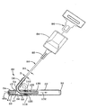
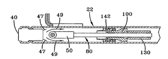
図1〜4は、本発明の第1の実施形態の様々な特徴を示している。プリテンショナ20は、第1の端24および第2の端部26を有する押し出し成形されたスチール製の直線状チューブ22を有している。直線状チューブ22の端部24、26は開放されている。組み立てプロセス時に、パイロテクニック装置40を直線状チューブ22の内側に固定するクリンプ28が直線状チューブ22の端部24の近くに形成される。直線状チューブ22の端部26の先端30は、端部開口部32の直径をフェルール130の直径より小さくするように下方に圧延されている。パイロテクニック装置40は、公知の構成を有し、直線状チューブ22の端部24に挿入される。パイロテクニック装置は、図4に示されているようにクリンプ28および直線状チューブ22の圧延された端部34によって所定の位置に拘束される拡大ヘッド41を含んでよい。パイロテクニック装置40(図4には示されていない)は、パイロテクニック材料が充填されたハウジング46を有している。パイロテクニック装置40は、制御ユニットからの電流を受ける1本または2本以上のリード線またはワイヤ48aを含んでいる。パイロテクニック装置を作動させると、パイロテクニック装置40によって生成された燃焼生成物が、直線状チューブ22の領域36の近くに配置されたパイロテクニック装置のアーム開放端部45から出る。直線状チューブ22は、図1および4に示されているように直線状チューブ22の頂部22a上に配置された楕円形の開口部38を有している。パイロテクニック装置40の開放端部45は、箔47によって密閉され、パイロテクニック材料を保護している。
1-4 illustrate various features of the first embodiment of the present invention. The
プリテンショナ20は、曲線状チューブ50を通って延びる金属製ケーブルまたはワイヤロープ80の直径D1より大きい約1.5mmの直径Dの内壁52を有する曲線状チューブ50を含んでいる。直径の差は、曲線状チューブ50を曲げて、ケーブルの曲がった部分を受け入れるのを可能にする。曲線状チューブ50は、図示の実施形態では一定の曲率を有する中央セグメント54を含んでいる。一般に、曲線状チューブが互いに接する2つまたは3つ以上の曲線を用いて実現されるような滑らかさを有するかぎり、一定の曲率は必要とされない。中央部54は、領域または点56から始まり、曲線状チューブ50の点または領域58まで延びている。図示のように、中央セグメントは弧状の湾曲を有するように構成されている。曲線状チューブは、曲線状部分に対して概ね接線方向に向けられ、ケーブル80が内部を延びる円形から直線への遷移領域を形成する延長部60を含んでいる。曲線状チューブ50は、曲線から直線の遷移セグメント62を含んでいる。
The
組み立て時には、曲線状チューブ50が直線状チューブ22の開口部38内に配置される。曲線状チューブ50は、直線状セグメント62が直線状チューブ22の中央長手方向軸64と共線的である。この構成では、曲線状チューブ50の曲線から直線への遷移部62の中心は、直線状チューブ22の中心と共線的である。この関係は、図4および4Aにも見られる。図2および3では、曲線状チューブ50はパイロテクニック装置40から間隔を置いて配置されている。パイロテクニック装置とケーブル案内部として機能する曲線状チューブとの間の空間は、パイロテクニック装置の箔シールが拘束されずに移動して開くのを可能にし、燃焼生成物が直線状チューブを通って流れるときに、図4Bの矢印49で示されているように、曲線状チューブ50の下部の周りに直線状の流れが生じるはずである。図4および4Aでは、ピストン、ケーブルフェルール、およびケーブルが省略され、直線状チューブ22内の曲線状チューブ50の向きがより明確に示されていることに留意されたい。
At the time of assembly, the
図4Aでは、曲線状チューブ50の部分54、60は、直線状チューブ22の頂面22aに概ね垂直に向けられている。組み立て時には、ケーブル80が曲線状チューブ50に通される。図1に最もよく示されているように、ケーブル80の一端82は、プリテンショナの動作で使用される種類のシートベルトバックル84に直接連結されるかまたはバックル84に連結可能なフェルール85を通して連結されている。図1は、バックル84とロック関係に固定されようとしているシートベルトタング90を概略的に示している。当技術分野で公知の多数の方法の1つでタング90に固定または連結されたシートベルトシステム96の肩ベルト92、膝ベルト94の一部も概略的に示されている。ケーブル80は、可動ピストン100に固定された向かい合う端部86を含んでいる。ピストン100は、ケーブルの一端86の周りを覆うように示されている。フェルール130などのケーブル終端部材は、ケーブル80の端部86の周りを滑らされ縁曲げされ、それによってフェルール130とケーブル80が機械的に連結されている。
In FIG. 4A, the
ピストン100は、図5に示されているように、前部円筒形部102と後部円筒形部104とを含んでいる。ピストンの前部および後部102、104は、直線状チューブ22の内壁22bに滑りながら係合し、ピストンが直線状チューブ内を移動するときにピストン100を直線状チューブの長手方向軸64に揃ったままに維持する。ピストン100は、ケーブル80を受け入れる中央ボア105を有している。ピストンの前部および後部102、104は、協働してV字形溝、くぼみ、または拘束部106を形成している。ゴム製Oリングやスポンジ状材料などの弾性部材115は、複数の玉軸受120を弾性的に支持している。ピストン100は、より小さい直径の領域D2からより大きい直径の領域D3まで遷移する漏斗状の表面110を含んでいる。より大きい直径D3は、徐々に直線状チューブ22の内径のサイズに近くなっている。
The
ピストン100と曲線状チューブ50の曲線から直線への遷移セグメント62の端部との間に、通常、耐熱性または高温定格を有するエラストマで作られた可動可とう性シール142が配置されている。シール142は、火器で使用される詰綿または送弾筒と同様にチューブを密封している。ピストン100およびシール142は、端部104がシール142のくぼみ144に嵌り、シール142とピストン100が一緒に移動するときにピストン組立体140として機能する。シール142は、中央ボア148を有する本体146も含んでいる。本体146の頂部は、くぼみ144を形成するリップを含んでいる。本体146の反対側の端部は、2つの滑りまたはリップシール、すなわち、直線状チューブ22の内径に対する第1のシールおよび曲線状チューブ50の外径、特に曲線から直線への遷移セグメント62に対する第2のシール、として構成されている。本体146の反対側の端部は、先細りで可とう性の円筒形外壁150を含んでいる。可とう性の円筒形壁150はその最も薄い部分が一方の端部に位置するように外側に先細りになっている。本体146の反対側の端部は、可とう性の円筒形壁150と同心の、可とう性の円筒形内壁152を含んでいる。円筒形内壁152は、その最も薄い部分が端部に位置するように内側に先細りになっている。円筒形内壁152の内径は、曲線状チューブ50の曲線から直線への遷移セグメント62の周りに流体密封シールを形成している。2枚の壁150、152は先細りの円筒形キャビティ154を形成している。組み立て時には、シール142が曲線状チューブ50の曲線から直線への遷移セグメント62の端部の周りに配置され、ピストン100の端部104がくぼみ144内に受け入れられる。
Between the
図2および5は、作動させる前のプリテンショナ20の様々な部分の位置を示している。この構成では、ピストン100の端面114がくぼみ144に受け入れられる。密封部材142は、曲線状チューブ50の曲線から直線への遷移セグメント62に隣接しかつセグメント62の周りに位置している。各玉軸受120は、直線状チューブ内の、ピストンの狭い直径の部分112の周りに、Oリング118に隣接して、緩く受け入れられる。
2 and 5 show the position of the various parts of the
パイロテクニック装置40の作動時には、燃焼生成物が生成され、燃焼生成物は直線状チューブ22の領域36に進入する。その後、燃焼生成物は、直線状チューブ22内を流れ、曲線状チューブ50の外壁に沿って、曲線状チューブ50の曲線から直線への遷移セグメント62の周りと曲線状チューブ50の中央部54の周りを流れる。燃焼生成物は、先細りの円筒形キャビティ154に受け入れられ、リップ、シール、または壁150を直線状チューブ22の内径に押し付けて、リップ、シール、または壁150と直線状チューブ22の内径との間にシールを形成し、リップ、シール、または壁152を曲線状チューブ50の外径に押し付けてリップ、シール、または壁152と曲線状チューブ50の外径との間に他のシールを形成する。燃焼生成物は、高圧の気体を含み、密封部材142、ピストン100、Oリング118、および玉軸受120を高速に直線状チューブ22に沿って矢印132の方向に移動させる。移動するピストンはフェルール130を押し、フェルールとケーブル端部86は直線状チューブ22に沿って高速に移動する。ケーブルの端部86が移動すると、ケーブル80が曲線状チューブ50を通して引かれ、それによってシートベルトバックル84が矢印132の方向に移動し、この移動は、上述のように、弛みを取り、シートベルトシステムを車両の乗員の周りに締め付ける傾向がある。シール142は、曲線状チューブ50と係合したままであるが、曲線状チューブ50を通したガス漏れを防止する。シール142は、この事前に付与された張力が大きくなるにつれて曲線状チューブ50から分離していく。シール142、ピストン100、Oリング118、玉軸受120、およびフェルール130は、燃焼生成物に応じて、パイロテクニック装置40が作動してから約10ミリ秒後に直線状チューブ22の端部へ約100mm接近するように位置を変更される。
During operation of the
本発明の一実施形態では、ピストンの直径は直線状チューブ22の端部30の縮小時の直径より大きく、フェルール130の直径は直線状チューブ22の端部30の直径より大きくてよい。フェルールは、直線状チューブ22の端部30に衝撃を与えた場合、直線状チューブを変形させる。この衝撃は、エネルギーが直線状チューブ22を変形させるのに消費されるため、ケーブル80とバックル84およびケーブルに連結された他の部品の移動を減速させる。さらに、シートベルトシステムに多量の弛みがある場合、ピストン100は引き続き移動し、フェルールに接触している場合にはいくらか拡大している可能性のある直線状チューブの端部30に接触する。このように、より多くのエネルギーが吸収され、ピストンおよびフェルールおよびケーブルの移動が減速させられる。
In one embodiment of the present invention, the diameter of the piston may be greater than the reduced diameter of the
衝突が進行すると、シートベルトシステムおよびプリテンショナによって保護された車両の乗員は、前方に移動し、肩ベルト92および膝ベルト94に負荷をかける。この負荷は、矢印132の方向とは概ね逆の、矢印134によって示されている方向にバックル84およびケーブル80を引っ張る傾向がある。車両の乗員によってケーブルにかけられる力は、抑制が効かない場合、ピストンをその始動位置の方へ引き、再び弛ませる。ケーブルが移動し、それによって車両の乗員の周りに再び緩むのを防止するために、ピストンは、表面110および玉軸受120の形をした一方向ロック装置を有するように構成される。このようなロック装置は従来技術で使用されている。バックルが外側にその最初の位置の方へ移動すると、玉軸受がピストン100の傾斜面110を転がり、ピストン100の表面110と直線状チューブ22の内壁22bとの間に閉じ込められ、ピストン100を機械的にロックするため、玉軸受120の相対位置が変化する。この種の一方向ロック装置は、衝突時に力が発生したときにその力に応じてピストンを所定の位置に保持するか、あるいはピストンを矢印132と逆の方向に制御可能に移動させるように構成することができる。
As the collision progresses, the vehicle occupant protected by the seat belt system and the pretensioner moves forward and loads the
プリテンショナ20は、プリテンショナを車両またはシート構造に取り付ける働きをする、ハウジングやブラケットなどの取り付け部材160をさらに含んでいる。取り付け部材160は、取り付け固定具(不図示)を受け入れて部材160を車両またはシートに固定するための取り付け穴163を有するプレート部162を含んでいる。プレート部162は、それぞれ溶接やろう付けなどによって曲線状および直線状チューブ50、22に固定された頂部および下部曲線部またはタブ166、168を含んでいる。タブ166、168は、曲線状チューブ50の移動を防止する。プレート部162は、タブ166、168から逆方向に曲げられ、プレート部162から外側に延び、プリテンショナ20を取り付け面に適切に揃える配置タブを形成する。
The
本発明は、プリテンショナ20を車両組み立て工場に輸送しているときの火災時または自動車自体内での火災時に生じる極端な温度に対する耐熱性を有するプリテンショナ20を提供する。この保護は、従来技術で使用されているようにパイロテクニック装置40を収納する従来の亜鉛ダイカスト構成部材とは異なりスチール製チューブ22、50によって実現される。パイロテクニック装置は、極度の高熱または炎のような熱源にさらされると、気体発生組成物が自動着火する前に軟化および溶融を開始し、溶融した金属を装置から突き出させることができる。本発明で使用され、パイロテクニック装置40を収納するスチール製チューブ22、50のガラス転移温度は、亜鉛ダイカストのガラス転移温度より数倍高く、したがって、車両の乗員または緊急隊員が負傷する可能性が低くなる。
The present invention provides a pretensioner 20 that has heat resistance against extreme temperatures that occur during a fire when the
このプリテンショナの他の態様は、事前張力付与時およびその後のシートベルトバックルの加速および減速に関して、交互に測定によるエネルギー管理を行うことである。過度に加速すると、シートベルトバックル84の内部構成部材が損傷し、いくつかの対策を使用してこのような影響を軽減させることが必要になることが分かっている。本発明では、第1の減速部材は、直線状チューブ22の先細り部に接触し、直線状チューブをわずかに変形させ、エネルギーを吸収するフェルール130である。
Another aspect of this pretensioner is to perform energy management by measurement alternately with respect to acceleration and deceleration of the seat belt buckle during pre-tensioning and thereafter. Excessive acceleration has been found to damage the internal components of the
本発明はさらに、より有効なケーブル遷移経路を提供する。最も古いプリテンショナは、方向変更部材として機能するプーリまたは鋳造ケーブルチャネルを含んでいる。ケーブルは、これらの装置の周りで引かれると、摩擦レベルが高くなり、プリテンショナの性能に影響を及ぼし、効率を低下させる。亜鉛鋳造物のようなより柔らかな材料とは異なり硬化された材料を使用してケーブル経路を形成すると、ケーブル、たとえば撚線ロープが、より柔らかい支持材料に食い込むことはなくなる。本発明のプリテンショナのケーブル経路は、従来技術の欠点を解消するのに十分な大きさの直径を有する曲線状チューブ50によって形成される。
The present invention further provides a more effective cable transition path. The oldest pretensioners include pulleys or cast cable channels that function as redirecting members. As the cable is pulled around these devices, the level of friction increases, affecting the performance of the pretensioner and reducing efficiency. When a cable path is formed using a hardened material, unlike softer materials such as zinc castings, cables, such as stranded rope, do not bite into the softer support material. The cable path of the pretensioner of the present invention is formed by a
Claims (12)
円筒形の壁と、第1の端および第2の端とを有する直線状チューブと、
前記直線状チューブ内に配置され、燃焼生成物を生成して、ピストンを前記直線状チューブの内部に沿って駆動するパイロテクニック装置と、を有し、
前記直線状チューブは、前記壁に設けられた、曲線状チューブを受け入れる開口部を有し、前記曲線状チューブは、第1の端部と、第2の端部と、円形から直線へ移行する遷移部を含む曲線状中央セグメントとを有するとともに、前記直線状チューブに固定され、前記曲線状チューブ内には、前記ピストンに連結されたケーブルが延びており、
前記ピストンは、該ピストンの運動によって、車両の乗員の周りのベルトの弛みを少なくするようにシートベルトを移動させる方向にケーブルを移動させることにより、シートベルトを移動させる、シートベルトプリテンショナ。 A seat belt pretensioner,
A linear tube having a cylindrical wall and a first end and a second end;
A pyrotechnical device disposed within the linear tube to generate combustion products and drive a piston along the interior of the linear tube;
The straight tube has an opening provided in the wall for receiving a curved tube, and the curved tube transitions from a first end and a second end to a straight line from a circle. A curved central segment including a transition portion, and fixed to the straight tube, and a cable connected to the piston extends in the curved tube,
A seat belt pretensioner in which the piston moves the seat belt by moving the cable in a direction to move the seat belt so as to reduce slack of the belt around the vehicle occupant by movement of the piston.
Applications Claiming Priority (2)
| Application Number | Priority Date | Filing Date | Title |
|---|---|---|---|
| US11/421,165 | 2006-05-31 | ||
| US11/421,165 US7533902B2 (en) | 2006-05-31 | 2006-05-31 | Seat belt pretensioner using preformed tubes |
Related Parent Applications (1)
| Application Number | Title | Priority Date | Filing Date |
|---|---|---|---|
| JP2009510939A Division JP5129241B2 (en) | 2006-05-31 | 2007-02-09 | Seat belt pretensioner |
Publications (2)
| Publication Number | Publication Date |
|---|---|
| JP2012166786A true JP2012166786A (en) | 2012-09-06 |
| JP5394539B2 JP5394539B2 (en) | 2014-01-22 |
Family
ID=38778962
Family Applications (2)
| Application Number | Title | Priority Date | Filing Date |
|---|---|---|---|
| JP2009510939A Expired - Fee Related JP5129241B2 (en) | 2006-05-31 | 2007-02-09 | Seat belt pretensioner |
| JP2012134067A Expired - Fee Related JP5394539B2 (en) | 2006-05-31 | 2012-06-13 | Seat belt pretensioner |
Family Applications Before (1)
| Application Number | Title | Priority Date | Filing Date |
|---|---|---|---|
| JP2009510939A Expired - Fee Related JP5129241B2 (en) | 2006-05-31 | 2007-02-09 | Seat belt pretensioner |
Country Status (8)
| Country | Link |
|---|---|
| US (1) | US7533902B2 (en) |
| EP (2) | EP2292479B1 (en) |
| JP (2) | JP5129241B2 (en) |
| KR (1) | KR100957256B1 (en) |
| CN (1) | CN101454184B (en) |
| DE (1) | DE602007011631D1 (en) |
| RU (1) | RU2386556C1 (en) |
| WO (1) | WO2007139599A1 (en) |
Cited By (2)
| Publication number | Priority date | Publication date | Assignee | Title |
|---|---|---|---|---|
| JP2018034550A (en) * | 2016-08-29 | 2018-03-08 | 株式会社東海理化電機製作所 | Buckle device |
| JP7001492B2 (en) | 2018-02-26 | 2022-01-19 | オートリブ ディベロップメント エービー | How to manufacture a seatbelt pretensioner and a seatbelt pretensioner |
Families Citing this family (44)
| Publication number | Priority date | Publication date | Assignee | Title |
|---|---|---|---|---|
| US7263750B2 (en) | 2005-06-09 | 2007-09-04 | Amsafe, Inc. | Buckle assembly having single release for multiple belt connectors |
| DE102005049659B3 (en) * | 2005-10-18 | 2007-04-05 | Autoliv Development Ab | Tightening device for safety belt system in motor vehicle has piston, which is formed in form of olive, with radius in longitudinal direction of pipe is larger than effective radius in transverse direction of pipe |
| WO2009008039A1 (en) * | 2007-07-06 | 2009-01-15 | Autoliv Development Ab | Pretensioner and process for manufacturing the same |
| US7823924B2 (en) * | 2008-06-24 | 2010-11-02 | Autoliv Asp, Inc. | Seatbelt pretensioner for a vehicle |
| FR2933351B1 (en) | 2008-07-07 | 2010-08-13 | Autoliv Dev | SAFETY DEVICE FOR A SEAT OF A MOTOR VEHICLE |
| KR100968829B1 (en) * | 2008-08-29 | 2010-07-08 | 현대자동차주식회사 | Seat belt pretensioner |
| US8303043B2 (en) | 2008-09-29 | 2012-11-06 | Amsafe, Inc. (Phoenix Group) | Tensioning apparatuses for occupant restraint systems and associated systems and methods |
| JP2010095080A (en) * | 2008-10-15 | 2010-04-30 | Tokai Rika Co Ltd | Pre-tensioner |
| JP5473322B2 (en) * | 2008-12-29 | 2014-04-16 | テイ・エス テック株式会社 | Vehicle seat |
| US8469401B2 (en) | 2009-02-23 | 2013-06-25 | Amsafe, Inc. | Seat harness pretensioner |
| JP5399183B2 (en) * | 2009-09-18 | 2014-01-29 | 株式会社東海理化電機製作所 | Pretensioner |
| CA2719846A1 (en) | 2009-11-02 | 2011-05-02 | Amsafe Commercial Products, Inc. | Devices for adjusting tension in seat belts and other restraint system webs, and associated methods |
| WO2011056989A1 (en) | 2009-11-04 | 2011-05-12 | Amsafe Commercial Products, Inc. | Restraint system buckle components having tactile surfaces, and associated methods of use and manufacture |
| US7997620B1 (en) * | 2010-03-10 | 2011-08-16 | GM Global Technology Operations LLC | Adaptive load-limiting seat belt buckle presenter |
| JP5011415B2 (en) * | 2010-03-25 | 2012-08-29 | オートリブ ディベロップメント エービー | Seat belt device |
| US8627554B1 (en) | 2010-05-03 | 2014-01-14 | Amsafe, Inc. (Phoenix Group) | Buckle assemblies with swivel and dual release features and associated methods of use and manufacture |
| US8585090B2 (en) | 2010-06-29 | 2013-11-19 | Autoliv Asp, Inc. | High efficiency pretensioner |
| US8777323B2 (en) | 2010-07-20 | 2014-07-15 | Amsafe, Inc. | Restraint harnesses and associated methods of use and manufacture |
| USD655223S1 (en) | 2010-09-15 | 2012-03-06 | Amsafe Commercial Products, Inc. | Buckle assembly |
| USD661619S1 (en) | 2010-09-15 | 2012-06-12 | Amsafe Commercial Products, Inc. | Buckle assembly |
| CN102205832B (en) * | 2011-01-26 | 2012-11-28 | 浙江吉利汽车研究院有限公司 | Safety belt spring bolt structure with locking function |
| DE102011108349A1 (en) * | 2011-07-25 | 2013-01-31 | Trw Automotive Gmbh | Tensor for a safety belt |
| US9200881B1 (en) | 2011-10-24 | 2015-12-01 | F. Richard Langner | Systems and methods for an improved firing assembly |
| US9322625B1 (en) | 2011-10-24 | 2016-04-26 | F. Richard Langner | Systems and methods for launching water from a disrupter cannon |
| US8915004B1 (en) * | 2011-10-24 | 2014-12-23 | F. Richard Langner | Systems and methods for a firing pin |
| US8528987B2 (en) | 2012-01-30 | 2013-09-10 | Autoliv Asp, Inc. | Linear seat belt pretensioner |
| US9022483B2 (en) | 2012-06-07 | 2015-05-05 | Shield Restraint Systems, Inc. | Seatbelt buckle tongue assembly |
| EP2958453A4 (en) | 2013-02-19 | 2016-07-27 | Amsafe Inc | Buckle assemblies with lift latches and associated methods and systems |
| US9277788B2 (en) | 2013-02-19 | 2016-03-08 | Amsafe, Inc. | Dual release buckle assemblies and associated systems and methods |
| US8814211B1 (en) * | 2013-03-14 | 2014-08-26 | Autoliv Asp, Inc. | Linear pretensioner for motor vehicle seatbelt restraint systems |
| CN103223919A (en) * | 2013-05-08 | 2013-07-31 | 黄绍勇 | Automobile safety belt pretensioner |
| JP6173812B2 (en) * | 2013-07-18 | 2017-08-02 | タカタ株式会社 | Vehicle seat |
| KR101366609B1 (en) | 2013-09-17 | 2014-02-25 | 장옥 | Multi-functional buckle device for seat belt |
| DE102014002006B4 (en) * | 2014-02-17 | 2022-08-04 | Zf Automotive Germany Gmbh | Pretensioner for a vehicle safety device |
| JP6310350B2 (en) * | 2014-07-18 | 2018-04-11 | 株式会社東海理化電機製作所 | Buckle device |
| US9775410B2 (en) | 2014-12-16 | 2017-10-03 | Shield Restraint Systems, Inc. | Web adjusters for use with restraint systems and associated methods of use and manufacture |
| FR3042756B1 (en) * | 2015-10-22 | 2019-06-21 | Renault S.A.S. | VEHICLE COMPRISING AT LEAST ONE IMPROVED BELT PRETENSIONER |
| US10604259B2 (en) | 2016-01-20 | 2020-03-31 | Amsafe, Inc. | Occupant restraint systems having extending restraints, and associated systems and methods |
| JP2017128311A (en) * | 2016-01-22 | 2017-07-27 | 株式会社東海理化電機製作所 | Buckle device |
| US9814282B2 (en) | 2016-02-02 | 2017-11-14 | Shield Restraint Systems, Inc. | Harsh environment buckle assemblies and associated systems and methods |
| WO2018148221A1 (en) | 2017-02-07 | 2018-08-16 | Shield Restraint Systems, Inc. | Web adjuster |
| JP6977641B2 (en) * | 2018-03-20 | 2021-12-08 | トヨタ自動車株式会社 | Vehicle seat belt device |
| JP7040407B2 (en) * | 2018-11-05 | 2022-03-23 | トヨタ自動車株式会社 | Vehicle seat |
| DE102020103913A1 (en) | 2020-02-14 | 2021-08-19 | Autoliv Development Ab | Tensioning device for a seat belt component |
Citations (5)
| Publication number | Priority date | Publication date | Assignee | Title |
|---|---|---|---|---|
| JPH106925A (en) * | 1996-03-28 | 1998-01-13 | Trw Occupant Restraint Syst Gmbh | Occupant restraint device provided with belt pretension device |
| JP2001039268A (en) * | 1999-07-27 | 2001-02-13 | Mazda Motor Corp | Occupant crash protection device for vehicle |
| JP2001225723A (en) * | 2000-02-15 | 2001-08-21 | Honda Motor Co Ltd | Pretensioner for seat belt device |
| JP2003127829A (en) * | 2001-08-10 | 2003-05-08 | Takata Corp | Pretensioner |
| JP2007022519A (en) * | 2005-06-17 | 2007-02-01 | Tokai Rika Co Ltd | Pre-loader |
Family Cites Families (26)
| Publication number | Priority date | Publication date | Assignee | Title |
|---|---|---|---|---|
| DE3729505A1 (en) | 1987-09-03 | 1989-03-23 | Bsrd Ltd | DEVICE FOR TIGHTENING A SEAT BELT OF A VEHICLE, IN PARTICULAR MOTOR VEHICLE |
| DE4201359A1 (en) * | 1992-01-20 | 1993-07-22 | Trw Repa Gmbh | BELT TENSIONER WITH PYROTECHNICAL PISTON / CYLINDER DRIVE |
| DE4201374A1 (en) * | 1992-01-20 | 1993-07-22 | Trw Repa Gmbh | DRIVE UNIT IN A RESTRAINT SYSTEM FOR VEHICLE PASSENGERS |
| DE4307062A1 (en) * | 1993-03-06 | 1994-09-08 | Trw Repa Gmbh | Belt tensioners for seat belt systems in vehicles |
| DE9303276U1 (en) * | 1993-03-06 | 1993-04-22 | Trw Repa Gmbh, 7077 Alfdorf, De | |
| DE4332206C2 (en) * | 1993-09-22 | 1997-08-14 | Hs Tech & Design | Drive device |
| GB9516540D0 (en) * | 1995-08-11 | 1995-10-11 | Alliedsignal Ltd | Pretensioner |
| US5639120A (en) | 1995-09-27 | 1997-06-17 | Ford Motor Company | Seat belt buckle pretensioner with end cap |
| US5676397A (en) | 1995-10-05 | 1997-10-14 | Trw Vehicle Safety Systems Inc. | Seat belt pretensioner including flexible strap |
| CZ121597A3 (en) * | 1996-04-23 | 1997-11-12 | Trw Repa Gmbh | Vehicle seat with integrated tension mechanism of the belt |
| US5887897A (en) * | 1997-02-06 | 1999-03-30 | Breed Automoive Technology, Inc. | Apparatus for pretensioning a vehicular seat belt |
| US5944350A (en) * | 1997-11-14 | 1999-08-31 | Takata Inc. | Buckle pretensioner |
| US5924730A (en) * | 1998-02-17 | 1999-07-20 | Breed Automotive Technology, Inc. | Pretensioning buckle |
| US6238003B1 (en) * | 1998-10-13 | 2001-05-29 | Breed Automotive Technology, Inc. | Outboard sill pretensioner |
| US6264281B1 (en) * | 1999-08-25 | 2001-07-24 | Daimlerchrysler Corporation | Seat belt buckle pretensioner mounting mechanism |
| JP4448626B2 (en) * | 2001-07-18 | 2010-04-14 | 本田技研工業株式会社 | Crew protection device |
| US6866296B2 (en) * | 2001-11-14 | 2005-03-15 | Delphi Technologies, Inc. | Seat restraint tensioner |
| JP2003237533A (en) * | 2002-02-21 | 2003-08-27 | Araco Corp | Vehicle seat |
| JP4573295B2 (en) * | 2004-01-14 | 2010-11-04 | タカタ株式会社 | Seat belt device |
| ATE398557T1 (en) | 2002-06-06 | 2008-07-15 | Autoliv Dev | IMPROVEMENTS TO OR RELATING TO A PRETENSIONER |
| DE20209284U1 (en) * | 2002-06-14 | 2003-10-16 | Breed Automotive Tech | Seat belt tensioning device |
| DE60203165T2 (en) * | 2002-06-14 | 2005-12-29 | Key Safety Systems, Inc., Sterling Heights | biasing device |
| US6840544B2 (en) * | 2002-11-19 | 2005-01-11 | Key Safety Systems, Inc. | Restraint system tensioning device with load limiting capability |
| US7159478B2 (en) * | 2004-04-14 | 2007-01-09 | Takata Seat Belts Inc. | Pretensioner testing apparatus and method |
| US7380832B2 (en) * | 2005-04-05 | 2008-06-03 | Takata Seat Belts, Inc. | Pretensioner with integrated gas generator |
| DE102005041678B3 (en) * | 2005-09-01 | 2006-11-02 | Autoliv Development Ab | Taut unit for seatbelt system, has layer of nitrogen particles formed to inner circumference of taut pipe |
-
2006
- 2006-05-31 US US11/421,165 patent/US7533902B2/en not_active Expired - Fee Related
-
2007
- 2007-02-09 CN CN2007800198025A patent/CN101454184B/en active Active
- 2007-02-09 JP JP2009510939A patent/JP5129241B2/en not_active Expired - Fee Related
- 2007-02-09 EP EP10015944A patent/EP2292479B1/en active Active
- 2007-02-09 RU RU2008147132/11A patent/RU2386556C1/en not_active IP Right Cessation
- 2007-02-09 WO PCT/US2007/003518 patent/WO2007139599A1/en active Application Filing
- 2007-02-09 DE DE602007011631T patent/DE602007011631D1/en active Active
- 2007-02-09 KR KR1020087025129A patent/KR100957256B1/en not_active IP Right Cessation
- 2007-02-09 EP EP07750361A patent/EP2051882B1/en active Active
-
2012
- 2012-06-13 JP JP2012134067A patent/JP5394539B2/en not_active Expired - Fee Related
Patent Citations (5)
| Publication number | Priority date | Publication date | Assignee | Title |
|---|---|---|---|---|
| JPH106925A (en) * | 1996-03-28 | 1998-01-13 | Trw Occupant Restraint Syst Gmbh | Occupant restraint device provided with belt pretension device |
| JP2001039268A (en) * | 1999-07-27 | 2001-02-13 | Mazda Motor Corp | Occupant crash protection device for vehicle |
| JP2001225723A (en) * | 2000-02-15 | 2001-08-21 | Honda Motor Co Ltd | Pretensioner for seat belt device |
| JP2003127829A (en) * | 2001-08-10 | 2003-05-08 | Takata Corp | Pretensioner |
| JP2007022519A (en) * | 2005-06-17 | 2007-02-01 | Tokai Rika Co Ltd | Pre-loader |
Cited By (3)
| Publication number | Priority date | Publication date | Assignee | Title |
|---|---|---|---|---|
| JP2018034550A (en) * | 2016-08-29 | 2018-03-08 | 株式会社東海理化電機製作所 | Buckle device |
| US10351095B2 (en) | 2016-08-29 | 2019-07-16 | Kabushiki Kaisha Tokai-Rika-Denki-Seisakusho | Buckle device |
| JP7001492B2 (en) | 2018-02-26 | 2022-01-19 | オートリブ ディベロップメント エービー | How to manufacture a seatbelt pretensioner and a seatbelt pretensioner |
Also Published As
| Publication number | Publication date |
|---|---|
| CN101454184B (en) | 2010-12-29 |
| EP2292479A3 (en) | 2011-03-30 |
| US7533902B2 (en) | 2009-05-19 |
| JP5394539B2 (en) | 2014-01-22 |
| KR20080100491A (en) | 2008-11-18 |
| WO2007139599A1 (en) | 2007-12-06 |
| JP5129241B2 (en) | 2013-01-30 |
| EP2051882B1 (en) | 2010-12-29 |
| EP2051882A1 (en) | 2009-04-29 |
| EP2292479B1 (en) | 2012-07-04 |
| US20070278779A1 (en) | 2007-12-06 |
| EP2292479A2 (en) | 2011-03-09 |
| JP2009537382A (en) | 2009-10-29 |
| EP2051882A4 (en) | 2009-12-23 |
| KR100957256B1 (en) | 2010-05-12 |
| RU2386556C1 (en) | 2010-04-20 |
| CN101454184A (en) | 2009-06-10 |
| DE602007011631D1 (en) | 2011-02-10 |
Similar Documents
| Publication | Publication Date | Title |
|---|---|---|
| JP5394539B2 (en) | Seat belt pretensioner | |
| CN101492038B (en) | Pretensioner and seat belt apparatus | |
| US8585090B2 (en) | High efficiency pretensioner | |
| JP4242520B2 (en) | Seat belt device | |
| US7350734B2 (en) | Seat belt pretensioner | |
| KR100455641B1 (en) | Seat belt pretensioner | |
| EP1892163B1 (en) | Pretensioner | |
| CA2146977A1 (en) | Seat belt pretensioner | |
| US8226122B2 (en) | Thin linear seatbelt pretensioner | |
| EP2671764A1 (en) | Pretensioner device and seat belt device | |
| MXPA06014904A (en) | Safety belt tensioning device comprising a tube with a bottleneck. | |
| US9371055B2 (en) | Pre-tensioning mechanism | |
| JP2010116142A (en) | Pretensioner | |
| EP1201513B1 (en) | Soft-start piston actuator | |
| JP2020132144A (en) | Retractor pretensioner assembly | |
| US6095615A (en) | Occupant restraint system with a belt pretensioner | |
| JP5108643B2 (en) | Preloader | |
| WO2006044541A2 (en) | Seatbelt pretensioner | |
| JP5027033B2 (en) | Preloader | |
| US20230001884A1 (en) | Pretensioner tube for a belt tensioner | |
| EP1532025B1 (en) | A pre-tensioner | |
| JP5291416B2 (en) | Limiting device and method of assembling limiting device | |
| JP2023012221A (en) | Pretensioner |
Legal Events
| Date | Code | Title | Description |
|---|---|---|---|
| A621 | Written request for application examination |
Free format text: JAPANESE INTERMEDIATE CODE: A621 Effective date: 20120613 |
|
| TRDD | Decision of grant or rejection written | ||
| A01 | Written decision to grant a patent or to grant a registration (utility model) |
Free format text: JAPANESE INTERMEDIATE CODE: A01 Effective date: 20131001 |
|
| A61 | First payment of annual fees (during grant procedure) |
Free format text: JAPANESE INTERMEDIATE CODE: A61 Effective date: 20131016 |
|
| R150 | Certificate of patent or registration of utility model |
Ref document number: 5394539 Country of ref document: JP Free format text: JAPANESE INTERMEDIATE CODE: R150 Free format text: JAPANESE INTERMEDIATE CODE: R150 |
|
| R250 | Receipt of annual fees |
Free format text: JAPANESE INTERMEDIATE CODE: R250 |
|
| R250 | Receipt of annual fees |
Free format text: JAPANESE INTERMEDIATE CODE: R250 |
|
| R250 | Receipt of annual fees |
Free format text: JAPANESE INTERMEDIATE CODE: R250 |
|
| S343 | Written request for registration of root pledge or change of root pledge |
Free format text: JAPANESE INTERMEDIATE CODE: R316354 |
|
| SZ02 | Written request for trust registration |
Free format text: JAPANESE INTERMEDIATE CODE: R316Z02 |
|
| R350 | Written notification of registration of transfer |
Free format text: JAPANESE INTERMEDIATE CODE: R350 |
|
| R250 | Receipt of annual fees |
Free format text: JAPANESE INTERMEDIATE CODE: R250 |
|
| R250 | Receipt of annual fees |
Free format text: JAPANESE INTERMEDIATE CODE: R250 |
|
| R250 | Receipt of annual fees |
Free format text: JAPANESE INTERMEDIATE CODE: R250 |
|
| S531 | Written request for registration of change of domicile |
Free format text: JAPANESE INTERMEDIATE CODE: R316531 Free format text: JAPANESE INTERMEDIATE CODE: R313531 |
|
| S533 | Written request for registration of change of name |
Free format text: JAPANESE INTERMEDIATE CODE: R316533 |
|
| S803 | Written request for registration of cancellation of provisional registration |
Free format text: JAPANESE INTERMEDIATE CODE: R316803 |
|
| SZ03 | Written request for cancellation of trust registration |
Free format text: JAPANESE INTERMEDIATE CODE: R313Z03 |
|
| S531 | Written request for registration of change of domicile |
Free format text: JAPANESE INTERMEDIATE CODE: R313531 |
|
| S343 | Written request for registration of root pledge or change of root pledge |
Free format text: JAPANESE INTERMEDIATE CODE: R316354 |
|
| SZ02 | Written request for trust registration |
Free format text: JAPANESE INTERMEDIATE CODE: R316Z02 |
|
| R350 | Written notification of registration of transfer |
Free format text: JAPANESE INTERMEDIATE CODE: R350 |
|
| R350 | Written notification of registration of transfer |
Free format text: JAPANESE INTERMEDIATE CODE: R350 |
|
| LAPS | Cancellation because of no payment of annual fees | ||
| S531 | Written request for registration of change of domicile |
Free format text: JAPANESE INTERMEDIATE CODE: R316531 |
|
| S533 | Written request for registration of change of name |
Free format text: JAPANESE INTERMEDIATE CODE: R316533 |
|
| R350 | Written notification of registration of transfer |
Free format text: JAPANESE INTERMEDIATE CODE: R350 |