JP2012166693A - Heat shield cover of railroad vehicle - Google Patents
Heat shield cover of railroad vehicle Download PDFInfo
- Publication number
- JP2012166693A JP2012166693A JP2011029456A JP2011029456A JP2012166693A JP 2012166693 A JP2012166693 A JP 2012166693A JP 2011029456 A JP2011029456 A JP 2011029456A JP 2011029456 A JP2011029456 A JP 2011029456A JP 2012166693 A JP2012166693 A JP 2012166693A
- Authority
- JP
- Japan
- Prior art keywords
- heat
- heat shield
- railway vehicle
- cover
- shield cover
- Prior art date
- Legal status (The legal status is an assumption and is not a legal conclusion. Google has not performed a legal analysis and makes no representation as to the accuracy of the status listed.)
- Granted
Links
Images


Abstract
Description
本発明は、車体の床下に艤装された発熱機器による熱から床や電線、隣接する機器の損傷を防ぐための鉄道車両の遮熱カバーに関する。 The present invention relates to a heat shield cover for a railway vehicle for preventing damage to a floor, electric wires, and adjacent devices from heat generated by a heat generating device mounted under the floor of a vehicle body.
鉄道車両では、速度を減速させるためにエアブレーキによる機械的な方法の他、制動エネルギーを電気エネルギーに変換し、負荷の運動エネルギーを電源に回収する回生制動が利用されるものがある。その際、交流電動機がブレーキトルクを出力するようにインバータ装置を回生動作させ、インバータ装置が出力する回生電力を昇降圧チョッパ装置を介して蓄電装置あるいは、架線を介して電気的に接続された別の列車の動力として消費することで吸収する。しかしその際、回生電力を吸収しきれないときには、エネルギーが抵抗器を介して熱として放出される。 In some railway vehicles, in addition to a mechanical method using an air brake to reduce the speed, regenerative braking is used in which braking energy is converted into electric energy and kinetic energy of a load is recovered by a power source. At that time, the inverter device is regeneratively operated so that the AC motor outputs the brake torque, and the regenerative power output by the inverter device is electrically connected via the buck-boost chopper device to the power storage device or via the overhead wire. It absorbs by consuming it as train power. However, at that time, when the regenerative power cannot be absorbed, energy is released as heat through the resistor.
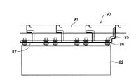
抵抗器は500℃程度の発熱に耐え得るものであるが、そこで発生した高熱は空気を介して車体の床へと伝わるため、高熱から床を保護するための構造が必要になる。図5及び図6は、抵抗器の取付構造を示した図であり、図5はレール方向に見た図で、図6は図5の右側から枕木方向に見た側面図である。抵抗器81は、走行風を通すようにメッシュの筐体82内に収められ、その筐体82が車体の床下に吊設されている。床90の横梁91に吊金具85が固定され、その吊金具85に対し碍子86を介して筐体82が吊設され、更に床90と筐体82との間には吊金具85に無機系絶縁材料の遮熱板87が固定されている。
The resistor can withstand a heat generation of about 500 ° C. However, since the high heat generated there is transmitted to the floor of the vehicle body via the air, a structure for protecting the floor from the high heat is required. 5 and 6 are views showing the resistor mounting structure, FIG. 5 is a view seen in the rail direction, and FIG. 6 is a side view seen from the right side of FIG. 5 in the sleeper direction. The
こうした従来の取付構造では、回生制動時に抵抗器81が500℃程度にまで発熱するが、その熱は遮熱板87によって遮断されるため床90が直接受けることはない。しかし、それでも抵抗器81からの熱は空気を介して200℃程度で床90に伝わってしまうため、熱による床の損傷は避けられなかった。こうした熱による床の損傷は寿命を縮めるなど好ましくはないため、更に遮熱効果を高めることが必要であった。
In such a conventional mounting structure, the
そこで、本発明は、かかる課題を解決すべく、床に対する遮熱効果を高めた鉄道車両の遮熱カバーを提供することを目的とする。 Therefore, an object of the present invention is to provide a heat shield cover for a railway vehicle with an enhanced heat shield effect on the floor in order to solve such a problem.
本発明に係る鉄道車両の遮熱カバーは、鉄道車両の車体床下に艤装された発熱機器を囲むようにして車体床下に取り付けられたものであって、前記発熱機器の少なくとも上方及びレール方向の前後両端部に遮熱板が配置されたカバー部と、前記鉄道車両の走行風が前記発熱機器に当たるように骨部材で形成され、走行風を上昇させる誘導部材を前記発熱機器の下に備えた通風部とを有するものであることを特徴とする。
また、本発明に係る鉄道車両の遮熱カバーは、前記誘導部材が板の上に起立板を備えたものであり、前記起立板は、枕木方向の幅がレール方向に従って徐々に狭くなるようにした流路部分を複数有し、その複数の流路部分は上から見て枕木方向に交互に逆転して配置されたものであることが好ましい。
また、本発明に係る鉄道車両の遮熱カバーは、前記起立板がノコ歯状に折り曲げられた板材であることが好ましい。
また、本発明に係る鉄道車両の遮熱カバーは、前記カバー部の上方及び側方に配置された遮熱板が隙間無く形成されたものであることが好ましい。
A heat shield cover for a railway vehicle according to the present invention is attached to the floor of a vehicle body so as to surround a heat generating device fitted under the vehicle body floor of the railway vehicle, and is at least above the heat generating device and both front and rear end portions in the rail direction. A cover portion in which a heat shield plate is disposed, and a ventilation portion that is formed of a bone member so that the traveling wind of the railway vehicle hits the heat generating device and includes a guide member that raises the traveling wind under the heat generating device; It is characterized by having.
Further, in the heat shield cover for a railway vehicle according to the present invention, the guide member is provided with an upright plate on the plate, and the upright plate has a width in the sleeper direction that gradually narrows according to the rail direction. It is preferable that a plurality of the flow path portions are provided, and the plurality of flow path portions are alternately reversed in the sleeper direction as viewed from above.
Moreover, it is preferable that the heat shield cover for a railway vehicle according to the present invention is a plate material in which the upright plate is bent in a sawtooth shape.
Moreover, it is preferable that the heat insulation cover of the railway vehicle which concerns on this invention is what the heat insulation board arrange | positioned above the said cover part and the side is formed without the clearance gap.
本発明の鉄道車両の遮熱カバーによれば、抵抗器などの発熱機器から放出された熱が、その発熱機器を囲んだカバー部によって上方へ伝わり難く床の加熱が抑えられ、通風部では、走行する鉄道車両の走行風が発熱機器へ直接当たる他、誘導部材の起立板によって上昇した走行風も当たって冷却が行われ、床に対する遮熱効果を高めることができる。 According to the heat shield cover of the railway vehicle of the present invention, the heat released from the heat generating device such as a resistor is not easily transmitted upward by the cover portion surrounding the heat generating device, and the floor heating is suppressed. The traveling wind of the traveling railway vehicle directly hits the heat generating device, and the traveling wind raised by the upright plate of the guide member also hits and cools, so that the heat shielding effect on the floor can be enhanced.
次に、本発明に係る鉄道車両の遮熱カバーについて、その実施形態を図面を参照しながら以下に説明する。本実施形態も抵抗器81の取付構造について説明する。従って、従来のものと同じ構成については同じ符号を付して説明する。図1及び図2は抵抗器の取付構造を示した図であり、図1はレール方向に見た断面図で、図2は図1の右側から枕木方向に見た側面図である。取付構造を構成する遮熱カバー10は、抵抗器81からの熱を遮断する従来の遮熱板87に代わるものであり、無機系絶縁材料によって形成されている。
Next, an embodiment of a heat shield cover for a railway vehicle according to the present invention will be described below with reference to the drawings. In this embodiment, the mounting structure of the
抵抗器81は、走行風を通すようにメッシュの筐体82内に収められ、その筐体82が車体の床下に吊設されている。床90の横梁91に吊金具88が固定され、その吊金具88に対し碍子86を介して筐体82が吊設され、更に吊金具88には遮熱カバー10が固定されている。ここで、図3は遮熱カバー10を示した斜視図である。この遮熱カバー10は、抵抗器81を納めた筐体82を覆うことにより、熱の伝達を遮断するとともに下方から風を当て抵抗器81に対する空冷効果を高めるようにしたものである。
The
遮熱カバー10は、骨組11に遮熱板12が張られたものであり、その遮熱板12が張られた骨組上部のカバー部10Aと、その下に骨組だけの通風部10Bとが構成されている。骨組11は、断面がL字形の部材が骨部材として使用され、カバー部10Aに張られた遮断板12は、上面板12aとレール方向の両端に位置する前後板12bと、図3には現れない枕木方向の車両中心側に位置する側面板12c(図1及び図2参照)とがある。なお、図面では詳しく示していないが、カバー部10Aと通風部10Bの各骨組は別体であって留め金によって一体にすることができるようになっている。
The
遮熱カバー10に収められた抵抗器81は、図1に示すように枕木方向の車体の片側に配置されており、遮熱板12は、車体側面に近い側(図3の手前側)には側面板が存在せずに開放した開放側面部13が形成されている。このように、遮熱カバー10は、抵抗器81の入った筐体82を囲む遮熱板12によって熱の上昇を防止し、遮熱板の無い開放側面部13から熱を外へ逃がすことができるようになっている。
The
また、遮熱カバー10は、通風部10Bには遮熱板12が存在しないため、走行風が抵抗器81に当たって空冷が行われるようになっている。ところが、この抵抗器81のレール方向前後には図示しないが、他の機器などが取り付けられており、走行風が十分には当たらないため空冷の効果が低い。このことは、本実施形態のように遮熱板12(特に前後板12b)が無い従来の取付構造であっても同様である。従って、遮熱板12は、従来のものと比べて空冷の効果を落とすわけではなく、隣接する機器や電線などへの熱の伝達を防止する点で有効である。この点、熱が開放側面部13以外に漏れないように、上面板12a、前後板12bおよび側面板12cが隙間無く構成されている。そして、本実施形態の遮熱カバー10には、抵抗器81に対する空冷効果を向上させるとともに、内部の熱が開放側面部13から放出されるように、走行風を下方から上方へと抵抗器81側へ導く誘導部材15が設けられている。
Moreover, since the
誘導部材15は、遮熱カバー10の底部に枕木方向に沿って設けられた底板15aと、底板15aの上に枕木方向に沿って山部と谷部とが交互に複数形成されたノコ歯状の起立板15bとから構成されている。起立板15bは、図示するようにリボン状の板材がつづら折りにして形成されたものであり、これが底板15aの上に起立した状態で接合されている。そして、こうした誘導部材15は、レール方向に見て遮熱カバー10の中央付近に配置されている。
The
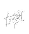
誘導部材15の起立板15bは、鉄道車両の走行方向に関係なく同じように山部と谷部とが生じるように形成されている。これは図4に示すように、山部151から谷部152(走行方向が逆転すれば山部151から谷部152も逆転する)へと流路155の幅(枕木方向の寸法)が狭くなるようにしたものであり、谷部152へ向かって流れ込んだ走行風が所定の範囲で上向きになるようにしたものである。
The standing
ところで誘導部材15は、水平に流れる走行風を上昇させて抵抗器81を冷却するよう構成されている。前述したように、発熱した抵抗器81を冷却するには水平方向の走行風だけでは十分ではなく、しかも鉄道車両が減速する短時間の間に発熱した抵抗器81を効率良く冷却する必要がある。それには、より効率的に走行風を当てることが望ましく、本実施形態は、上昇する走行風の流れを作りだすことにより、その目的を達成させるようにしたものである。特に誘導部材15は、流路155の幅が徐々に狭くなる形状にしたことで、行き場を失った走行風が段階的に上昇し、レール方向に見た所定距離の間で上昇風を作りだしている。
By the way, the
この点、仮に一枚の平板をレール方向に直交して立てただけの起立板では抵抗が大き過ぎてしまい、走行風が誘導部材の下側へ逃げて流れてしまうことが予想される。それでは、抵抗器81に向けて走行風を当てることができず、希望する冷却効果が得られない。また、レール方向に傾斜した山形の起立板などでは、その起立板を走行風がスムーズに乗り越える流れだけで、抵抗器81に当たる上昇風を作りだすことができないと考えられる。
In this regard, it is expected that a standing plate that is a single flat plate that stands up perpendicular to the rail direction will have too much resistance, and the traveling wind will escape and flow downward. Then, traveling wind cannot be applied toward the
そこで本実施形態の誘導部材15は、水平方向に流れる走行風を抵抗器81に当たる上昇風にし、且つレール方向(走行風の流れる方向)の広い範囲で抵抗器81に当たることで効率よく冷却できるように、起立板15bが形成されている。なお、加工の便宜から山部151と谷部152とを三角形状にしたが、湾曲した形状や台形形状で山部と谷部とを構成してもよい。また、起立板15bは底板15aに対して直交した形状であるが、山部や谷部を形成する壁を傾かせた形状のものも考えられる。
Therefore, the
そこで本実施形態の遮熱カバーでは、次のようにして床90に対する遮熱効果を高めることができる。走行中の鉄道車両が回生制動により減速する場合、吸収しきれない回生電力が抵抗器81を介して熱として放出される。その際、遮熱カバー10によれば、走行する鉄道車両の走行風により抵抗器81の冷却が行われるとともに、その抵抗器81から放出された高熱による床90の加熱が防止できる。また、上面板12a、前後板12bおよび側面板12cによって閉じられた遮熱板12によって、抵抗器81に隣接する機器や電線などへの熱による影響を防止できる。
Therefore, in the heat shield cover of this embodiment, the heat shield effect on the
すなわち、遮熱カバー10は通風部10Bが開放されているため、走行風が当たって抵抗器81が冷却され、更に誘導部材15の起立板15bにより走行風が上昇し、下からも走行風が当たって抵抗器81が冷却される。その遮熱カバー10は、起立板15bが走行風の流れる方向に流路155の断面積が徐々に小さくなっているので、広い範囲で上昇風を作りだし、効率よく抵抗器81を冷却することができる。鉄道車両が停止する場合、完全に停止するまでの間に如何に多くの走行風を抵抗器81に当てて冷却できるかが重要である。その点、本実施形態では下からも走行風を当てる構成であるため冷却効果は高い。また、誘導部材15がレール方向に見て遮熱カバー10の中央付近に配置されているため、走行風が通常では当たり難い抵抗器81の後方側にも当てることができるため、その点で冷却効率をより高めることができる。
That is, since the
また、抵抗器81から発せられた高熱は上方の床90に向かって伝わるが、本実施形態では、抵抗器81を囲んだ遮熱板12によって上方へは伝わり難く、床90の加熱が抑えられる。その際、カバー部10A内に高熱が滞留するが、前述したように誘導部材15によって下から走行風が送り込まれるため、滞留した高熱は開放側面部13から外へと送り出される。そして、開放側面部13は車体側面に面しているため、送り出された熱は走行風に流され、床90への影響は小さく抑えられる。また、鉄道車両が停止した状態では、走行風による冷却効果などは得られないが、遮熱板12が抵抗器81を囲んでいることにより床90や隣接する機器、電線などへの熱の伝達が抑えられる。
Moreover, although the high heat emitted from the
以上、本発明に係る鉄道車両の遮熱カバーについて実施形態を説明したが、本発明はこれに限定されることなく、その趣旨を逸脱しない範囲で様々な変更が可能である。
例えば、誘導部材15は、前述したように起立板15bの形状以外でも同様に効果を得ることができ、実施形態では誘導部材15をレール方向の中央に一つを配置した構成としたが、複数設けたり、寸法をレール方向に長いものとしたものであってもよい。
前記実施形態では抵抗器81を発熱機器の例として説明したが、その外にも例えば、半導体によって直流から交流に電力を変換するコンバーター装置、トランス・コイル(リアクトル)、蓄電池、キャパシタ、ディーゼルエンジンなどの内燃機関、発電機、液体変速機(トルクコンバーター)、排気管、消音器、放熱器が挙げられる。
また、前記実施形態では遮熱板12が、上面板12a、前後板12bおよび側面板12cによって構成されたもの示したが、例えば抵抗器が車体の全幅に配置されるものでは、枕木方向両側を開放側面にしてもよいため、その場合には上面板と前後板だけを配した構成になる。
As mentioned above, although embodiment was described about the thermal insulation cover of the rail vehicle which concerns on this invention, this invention is not limited to this, A various change is possible in the range which does not deviate from the meaning.
For example, as described above, the
In the above embodiment, the
In the above embodiment, the
10 遮熱カバー
10A カバー部
10B 通風部
11 骨組
12 遮熱板
15 誘導部材
81 抵抗器
82 筐体
90 床
DESCRIPTION OF
Claims (4)
前記発熱機器の少なくとも上方及びレール方向の前後両端部に遮熱板が配置されたカバー部と、
前記鉄道車両の走行風が前記発熱機器に当たるように骨部材で形成され、走行風を上昇させる誘導部材を前記発熱機器の下に備えた通風部とを有するものであることを特徴とする鉄道車両の遮熱カバー。 In the heat shield cover of the railway vehicle attached under the vehicle body floor so as to surround the heat generating equipment mounted under the vehicle body floor of the rail vehicle,
A cover part in which heat shield plates are arranged at least at the upper part of the heat generating device and at both front and rear ends in the rail direction;
The railway vehicle is formed of a bone member so that the traveling wind of the railway vehicle hits the heat generating device, and has a ventilation portion provided below the heat generating device with a guide member for raising the traveling wind. Heat shield cover.
前記誘導部材は、板の上に起立板を備えたものであり、前記起立板は、枕木方向の幅がレール方向に従って徐々に狭くなるようにした流路部分を複数有し、その複数の流路部分は上から見て枕木方向に交互に逆転して配置されたものであることを特徴とする鉄道車両の遮熱カバー。 In the heat shield cover for a railway vehicle according to claim 1,
The guide member is provided with an upright plate on a plate, and the upright plate has a plurality of flow path portions in which the width in the sleeper direction is gradually narrowed in the rail direction, and the plurality of flow paths are provided. A heat insulation cover for a railway vehicle, characterized in that the road portion is alternately reversed in the sleeper direction as viewed from above.
前記起立板は、ノコ歯状に折り曲げられた板材であることを特徴とする鉄道車両の遮熱カバー。 In the heat shield cover for a railway vehicle according to claim 2,
The heat-insulating cover for a railway vehicle, wherein the upright plate is a plate material bent into a sawtooth shape.
前記カバー部は、上方及び側方に配置された遮熱板が隙間無く形成されたものであることを特徴とする鉄道車両の遮熱カバー。 In the heat shield cover for a railway vehicle according to any one of claims 1 to 3,
A heat shield cover for a railway vehicle, wherein the cover portion is formed by a heat shield plate disposed on the upper side and the side without gaps.
Priority Applications (1)
| Application Number | Priority Date | Filing Date | Title |
|---|---|---|---|
| JP2011029456A JP5769980B2 (en) | 2011-02-15 | 2011-02-15 | Rail vehicle heat shield cover |
Applications Claiming Priority (1)
| Application Number | Priority Date | Filing Date | Title |
|---|---|---|---|
| JP2011029456A JP5769980B2 (en) | 2011-02-15 | 2011-02-15 | Rail vehicle heat shield cover |
Publications (2)
| Publication Number | Publication Date |
|---|---|
| JP2012166693A true JP2012166693A (en) | 2012-09-06 |
| JP5769980B2 JP5769980B2 (en) | 2015-08-26 |
Family
ID=46971272
Family Applications (1)
| Application Number | Title | Priority Date | Filing Date |
|---|---|---|---|
| JP2011029456A Active JP5769980B2 (en) | 2011-02-15 | 2011-02-15 | Rail vehicle heat shield cover |
Country Status (1)
| Country | Link |
|---|---|
| JP (1) | JP5769980B2 (en) |
Cited By (2)
| Publication number | Priority date | Publication date | Assignee | Title |
|---|---|---|---|---|
| WO2015190226A1 (en) * | 2014-06-13 | 2015-12-17 | 株式会社日立製作所 | Railway vehicle provided with plurality of underfloor equipment |
| US9863302B2 (en) | 2011-12-09 | 2018-01-09 | Mitsubishi Electric Corporation | Cooling device for under-floor device for vehicle |
Citations (4)
| Publication number | Priority date | Publication date | Assignee | Title |
|---|---|---|---|---|
| JPS5465909A (en) * | 1977-11-05 | 1979-05-28 | Hitachi Ltd | Apparatus for cooling vehicle control device |
| JPS6216554U (en) * | 1985-07-17 | 1987-01-31 | ||
| JPH0692226A (en) * | 1992-09-16 | 1994-04-05 | Toshiba Corp | Control device for vehicle |
| JP2007182208A (en) * | 2005-12-09 | 2007-07-19 | Kinki Sharyo Co Ltd | Installation method and installation structure for underfloor equipment |
-
2011
- 2011-02-15 JP JP2011029456A patent/JP5769980B2/en active Active
Patent Citations (4)
| Publication number | Priority date | Publication date | Assignee | Title |
|---|---|---|---|---|
| JPS5465909A (en) * | 1977-11-05 | 1979-05-28 | Hitachi Ltd | Apparatus for cooling vehicle control device |
| JPS6216554U (en) * | 1985-07-17 | 1987-01-31 | ||
| JPH0692226A (en) * | 1992-09-16 | 1994-04-05 | Toshiba Corp | Control device for vehicle |
| JP2007182208A (en) * | 2005-12-09 | 2007-07-19 | Kinki Sharyo Co Ltd | Installation method and installation structure for underfloor equipment |
Cited By (3)
| Publication number | Priority date | Publication date | Assignee | Title |
|---|---|---|---|---|
| US9863302B2 (en) | 2011-12-09 | 2018-01-09 | Mitsubishi Electric Corporation | Cooling device for under-floor device for vehicle |
| WO2015190226A1 (en) * | 2014-06-13 | 2015-12-17 | 株式会社日立製作所 | Railway vehicle provided with plurality of underfloor equipment |
| JP2016002774A (en) * | 2014-06-13 | 2016-01-12 | 株式会社日立製作所 | Railway vehicle including multiple underfloor devices |
Also Published As
| Publication number | Publication date |
|---|---|
| JP5769980B2 (en) | 2015-08-26 |
Similar Documents
| Publication | Publication Date | Title |
|---|---|---|
| EP3130517B1 (en) | Moving vehicle | |
| WO2014203374A1 (en) | Vehicular power conversion device | |
| US9943007B2 (en) | Power converter for railroad vehicle | |
| JP4879370B1 (en) | Vehicle control device | |
| JP2000092819A (en) | Semiconductor cooling apparatus | |
| WO2018097271A1 (en) | Power conversion device for railway vehicle | |
| JP5769980B2 (en) | Rail vehicle heat shield cover | |
| EP2447961A1 (en) | Transformer | |
| JP2000134950A (en) | Power-converting device for vehicle | |
| JP2005286020A (en) | Mounting structure of reactor and vibration damping method | |
| WO2015198616A1 (en) | Power conversion device and vehicle control device | |
| JP2011151924A (en) | Power converter for railway vehicle | |
| CN209358383U (en) | A kind of frequency converter installation of variable-frequency power generation unit and cooling structure | |
| JP5305836B2 (en) | Railway vehicle power converter | |
| JP5827599B2 (en) | Railway vehicle power converter | |
| JP2007048741A (en) | Conductor and heat radiating structure of conductor | |
| JP2018079810A (en) | Vehicular power conversion device unit | |
| JP2018037642A (en) | Railway vehicle power conversion device | |
| JP6837565B2 (en) | Railroad vehicle power converters and railroad vehicles equipped with power converters | |
| JP2007244130A (en) | Power converter | |
| JP4421132B2 (en) | Railway vehicle power converter | |
| JP2005039914A (en) | Power converter for vehicle | |
| JP6359202B2 (en) | Transformer for vehicle | |
| CN203434844U (en) | Vehicle-mounted parallel auxiliary current transformer of railway vehicle and heat-radiation device thereof | |
| CN211951395U (en) | Rail transit vehicle gear box heat sink |
Legal Events
| Date | Code | Title | Description |
|---|---|---|---|
| A621 | Written request for application examination |
Free format text: JAPANESE INTERMEDIATE CODE: A621 Effective date: 20140116 |
|
| A977 | Report on retrieval |
Free format text: JAPANESE INTERMEDIATE CODE: A971007 Effective date: 20141118 |
|
| A131 | Notification of reasons for refusal |
Free format text: JAPANESE INTERMEDIATE CODE: A131 Effective date: 20141125 |
|
| A521 | Request for written amendment filed |
Free format text: JAPANESE INTERMEDIATE CODE: A523 Effective date: 20150112 |
|
| TRDD | Decision of grant or rejection written | ||
| A01 | Written decision to grant a patent or to grant a registration (utility model) |
Free format text: JAPANESE INTERMEDIATE CODE: A01 Effective date: 20150623 |
|
| A61 | First payment of annual fees (during grant procedure) |
Free format text: JAPANESE INTERMEDIATE CODE: A61 Effective date: 20150624 |
|
| R150 | Certificate of patent or registration of utility model |
Ref document number: 5769980 Country of ref document: JP Free format text: JAPANESE INTERMEDIATE CODE: R150 |
|
| R250 | Receipt of annual fees |
Free format text: JAPANESE INTERMEDIATE CODE: R250 |
|
| R250 | Receipt of annual fees |
Free format text: JAPANESE INTERMEDIATE CODE: R250 |
|
| R250 | Receipt of annual fees |
Free format text: JAPANESE INTERMEDIATE CODE: R250 |
|
| R250 | Receipt of annual fees |
Free format text: JAPANESE INTERMEDIATE CODE: R250 |
|
| R250 | Receipt of annual fees |
Free format text: JAPANESE INTERMEDIATE CODE: R250 |