JP2012166676A - Vehicle and control method therefor - Google Patents
Vehicle and control method therefor Download PDFInfo
- Publication number
- JP2012166676A JP2012166676A JP2011028821A JP2011028821A JP2012166676A JP 2012166676 A JP2012166676 A JP 2012166676A JP 2011028821 A JP2011028821 A JP 2011028821A JP 2011028821 A JP2011028821 A JP 2011028821A JP 2012166676 A JP2012166676 A JP 2012166676A
- Authority
- JP
- Japan
- Prior art keywords
- value
- vehicle
- driving force
- drive
- threshold value
- Prior art date
- Legal status (The legal status is an assumption and is not a legal conclusion. Google has not performed a legal analysis and makes no representation as to the accuracy of the status listed.)
- Granted
Links
Images


Classifications
-
- Y—GENERAL TAGGING OF NEW TECHNOLOGICAL DEVELOPMENTS; GENERAL TAGGING OF CROSS-SECTIONAL TECHNOLOGIES SPANNING OVER SEVERAL SECTIONS OF THE IPC; TECHNICAL SUBJECTS COVERED BY FORMER USPC CROSS-REFERENCE ART COLLECTIONS [XRACs] AND DIGESTS
- Y02—TECHNOLOGIES OR APPLICATIONS FOR MITIGATION OR ADAPTATION AGAINST CLIMATE CHANGE
- Y02T—CLIMATE CHANGE MITIGATION TECHNOLOGIES RELATED TO TRANSPORTATION
- Y02T10/00—Road transport of goods or passengers
- Y02T10/60—Other road transportation technologies with climate change mitigation effect
- Y02T10/62—Hybrid vehicles
Abstract
Description
本発明は、内燃機関と駆動輪とが機械的に連結された車両の駆動力の制御に関する。 The present invention relates to control of driving force of a vehicle in which an internal combustion engine and driving wheels are mechanically coupled.
車両が波状路等の悪路を走行している場合には、駆動輪に回転変動が生じて、動力源から駆動輪までの部品を含む駆動システムにおいて共振が発生する場合がある。発生した共振による過大な入力から部品を保護するため、たとえば、特開2009−040174号公報(特許文献1)には、路面の凹凸に応じて車両の駆動力を低下させる技術が開示されている。 When the vehicle is traveling on a rough road such as a wavy road, rotational fluctuations occur in the drive wheels, and resonance may occur in the drive system including components from the power source to the drive wheels. In order to protect parts from excessive input due to the generated resonance, for example, Japanese Unexamined Patent Application Publication No. 2009-040174 (Patent Document 1) discloses a technique for reducing the driving force of a vehicle in accordance with road surface unevenness. .
しかしながら、共振を検出して車両の走行路面が悪路であるか否かを判定する場合に誤判定すると、車両が悪路を走行していないときに車両の駆動力を低下させるという問題が生じる。上述した公報においては、このような問題について何ら考慮されておらず、誤判定の抑制には、改善の余地がある。 However, if it is erroneously determined when resonance is detected and it is determined whether or not the road surface of the vehicle is a rough road, there arises a problem that the driving force of the vehicle is reduced when the vehicle is not traveling on a bad road. . The above-mentioned publication does not consider such a problem at all, and there is room for improvement in suppressing erroneous determination.
本発明は、上述した課題を解決するためになされたものであって、その目的は、走行路面の誤判定を抑制して、走行路面に応じた駆動力制御を実現する車両および車両用制御方法を提供することである。 The present invention has been made to solve the above-described problem, and an object of the present invention is to provide a vehicle and a vehicle control method that suppresses erroneous determination of a traveling road surface and realizes driving force control according to the traveling road surface. Is to provide.
この発明のある局面に係る車両は、車両に駆動力を発生させるための駆動輪、内燃機関、および、内燃機関と駆動輪とを機械的に連結するための駆動伝達装置を含む駆動システムと、駆動輪および駆動輪の回転に連動して回転する部品のうちの少なくともいずれか一方についての回転速度を検出するための検出部と、検出部によって検出された回転速度に基づいて駆動力を制御するための制御部とを含む。制御部は、回転速度の変動成分の大きさが第1しきい値よりも大きい場合であって、かつ、積算値の増加傾向を示す値が第2しきい値よりも大きい場合には、駆動力を制限する。 A vehicle according to an aspect of the present invention includes a drive system including a drive wheel for generating a drive force in the vehicle, an internal combustion engine, and a drive transmission device for mechanically connecting the internal combustion engine and the drive wheel; A detection unit for detecting a rotation speed of at least one of the driving wheel and a part that rotates in conjunction with the rotation of the driving wheel, and a driving force is controlled based on the rotation speed detected by the detection unit. And a control unit. When the magnitude of the fluctuation component of the rotational speed is greater than the first threshold value and the value indicating the increasing tendency of the integrated value is greater than the second threshold value, the control unit drives Limit power.
好ましくは、制御部は、駆動力が制限された後において、変動成分の大きさが第1しきい値以下の第3しきい値よりも小さい場合には、変動成分の大きさに基づいて駆動力の復帰レートを決定し、決定された復帰レートにしたがって駆動力の制限を解除する。 Preferably, after the driving force is limited, the control unit drives based on the magnitude of the fluctuation component when the magnitude of the fluctuation component is smaller than a third threshold value equal to or less than the first threshold value. The force return rate is determined, and the driving force restriction is released according to the determined return rate.
さらに好ましくは、第1しきい値および第2しきい値は、いずれも駆動システムにおいて車両の悪路走行に起因した共振が発生していることを判定するための値である。制御部は、現在の時点以前の所定期間における回転速度の共振周波数帯における変動成分を抽出して、抽出された変動成分に基づいて変動成分の大きさを算出する。 More preferably, each of the first threshold value and the second threshold value is a value for determining that resonance has occurred due to a rough road traveling of the vehicle in the drive system. The control unit extracts a fluctuation component in the resonance frequency band of the rotation speed in a predetermined period before the current time point, and calculates the magnitude of the fluctuation component based on the extracted fluctuation component.
さらに好ましくは、制御部は、変動成分の大きさの所定期間における変化量が第4しきい値よりも大きくなる回数を増加傾向を示す値として算出する。 More preferably, the control unit calculates the number of times that the amount of change in the magnitude of the fluctuation component in the predetermined period becomes larger than the fourth threshold value as a value indicating an increasing tendency.
さらに好ましくは、駆動伝達装置は、駆動輪を回転させるための駆動軸と、第1回転電機と、駆動軸に設けられる第2回転電機と、駆動軸、内燃機関の出力軸および第1回転電機の回転軸の三要素の各々を機械的に連結し、三要素のうちのいずれか一つを反力要素とすることによって、他の2つの要素間での動力伝達が可能な動力伝達装置とを含む。 More preferably, the drive transmission device includes a drive shaft for rotating the drive wheels, a first rotating electrical machine, a second rotating electrical machine provided on the driving shaft, a drive shaft, an output shaft of the internal combustion engine, and the first rotating electrical machine. A power transmission device capable of transmitting power between the other two elements by mechanically connecting each of the three elements of the rotating shaft of the motor, and using any one of the three elements as a reaction force element; including.
この発明の他の局面に係る車両用制御方法は、駆動力を発生させるための駆動輪、内燃機関、および、内燃機関と駆動輪とを機械的に連結するための駆動伝達装置を含む駆動システムを搭載した車両に用いられる車両用制御方法である。この車両用制御方法は、駆動輪および駆動輪の回転に連動して回転する部品のうちの少なくともいずれか一方についての回転速度を検出するステップと、回転速度の変動成分の大きさが第1しきい値よりも大きい場合であって、かつ、変動成分の大きさの増加傾向を示す値が第2しきい値よりも大きい場合には、車両の駆動力を制限するステップとを含む。 A vehicle control method according to another aspect of the present invention includes a drive system including a drive wheel for generating a drive force, an internal combustion engine, and a drive transmission device for mechanically connecting the internal combustion engine and the drive wheel. It is the control method for vehicles used for the vehicle which mounts. In this vehicle control method, the step of detecting the rotational speed of at least one of the drive wheels and the parts that rotate in conjunction with the rotation of the drive wheels and the magnitude of the fluctuation component of the rotational speed are the first. And a step of limiting the driving force of the vehicle when the value indicating the increasing tendency of the magnitude of the fluctuation component is larger than the second threshold value.
本発明によると、駆動システムに振動が発生して、一時的に共振周波数帯の変動成分の大きさが増加した場合でも、増加傾向を示す値がしきい値を超えない限り、駆動力の制限が行なわれることを抑制することができる。そのため、車両が悪路を走行していると誤判定することを抑制することができる。また、車両が悪路を走行していると判定された場合には、駆動力の制限制御を実行することによって、駆動システムの部品の保護が図られる。したがって、走行路面の誤判定を抑制して、走行路面に応じた駆動力制御を実現する車両および車両用制御方法を提供することができる。 According to the present invention, even when a vibration occurs in the drive system and the magnitude of the fluctuation component of the resonance frequency band temporarily increases, as long as the value indicating the increase tendency does not exceed the threshold value, the drive force is limited. Can be suppressed. Therefore, erroneous determination that the vehicle is traveling on a rough road can be suppressed. In addition, when it is determined that the vehicle is traveling on a rough road, the driving force limiting control is executed to protect the components of the driving system. Therefore, it is possible to provide a vehicle and a vehicle control method that can suppress erroneous determination of the traveling road surface and realize driving force control according to the traveling road surface.
以下、図面を参照しつつ、本発明の実施の形態は、説明される。以下の説明では、同一の部品には同一の符号が付されている。それらの名称および機能も同じである。したがってそれらについての詳細な説明は繰り返されない。 Hereinafter, embodiments of the present invention will be described with reference to the drawings. In the following description, the same parts are denoted by the same reference numerals. Their names and functions are also the same. Therefore, detailed description thereof will not be repeated.
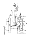
図1を参照して、本実施の形態に係る車両1の全体ブロック図が説明される。車両1は、PCU(Power Control Unit)60と、メインバッテリ70と、駆動システム84と、ECU(Electronic Control Unit)200とを含む。駆動システム84は、エンジン10と、第1モータジェネレータ(以下、第1MGと記載する)20と、第2モータジェネレータ(以下、第2MGと記載する)30と、駆動輪80と、トランスミッション86とを含む。トランスミッション86は、駆動軸16と、動力分割装置40と、減速機58と、ドライブシャフト82とを含む駆動力伝達装置である。
With reference to FIG. 1, an overall block diagram of a
この車両1は、エンジン10および第2MG30の少なくとも一方から出力される駆動力によって走行する。エンジン10が発生する動力は、動力分割装置40によって2経路に分割される。2経路のうちの一方の経路は減速機58を介して駆動輪80へ伝達される経路であり、他方の経路は第1MG20へ伝達される経路である。
The
第1MG20および第2MG30は、たとえば、三相交流回転電機である。第1MG20および第2MG30は、PCU60によって駆動される。 First MG 20 and second MG 30 are, for example, three-phase AC rotating electric machines. First MG 20 and second MG 30 are driven by PCU 60.
第1MG20は、動力分割装置40によって分割されたエンジン10の動力を用いて発電してPCU60を経由してメインバッテリ70を充電するジェネレータとしての機能を有する。また、第1MG20は、メインバッテリ70からの電力を受けてエンジン10の出力軸であるクランク軸を回転させる。これによって、第1MG20は、エンジン10を始動するスタータとしての機能を有する。
First MG 20 has a function as a generator that generates power using the power of
第2MG30は、メインバッテリ70に蓄えられた電力および第1MG20により発電された電力の少なくともいずれか一方を用いて駆動輪80に駆動力を与える駆動用モータとしての機能を有する。また、第2MG30は、回生制動によって発電された電力を用いてPCU60を経由してメインバッテリ70を充電するためのジェネレータとしての機能を有する。
Second MG 30 has a function as a drive motor that applies driving force to drive
エンジン10は、たとえば、ガソリンエンジンやディーゼルエンジン等の内燃機関である。エンジン10は、複数の気筒102を含む。さらに、エンジン10には、エンジン10のクランク軸の回転速度(以下、エンジン回転速度と記載する)Neを検出するためのエンジン回転速度センサ11が設けられる。エンジン回転速度センサ11は、検出されたエンジン回転速度Neを示す信号をECU200に送信する。
The
動力分割装置40は、駆動輪80を回転させるための駆動軸16、エンジン10の出力軸および第1MG20の回転軸の三要素の各々を機械的に連結する。動力分割装置40は、上述の三要素のうちのいずれか一つを反力要素とすることによって、他の2つの要素間での動力の伝達を可能とする。第2MG30の回転軸は、駆動軸16に連結される。
動力分割装置40は、サンギヤと、ピニオンギヤと、キャリアと、リングギヤとを含む遊星歯車機構である。ピニオンギヤは、サンギヤおよびリングギヤの各々と噛み合う。キャリアは、ピニオンギヤを自転可能に支持するとともに、エンジン10のクランク軸に連結される。サンギヤは、第1MG20の回転軸に連結される。リングギヤは、駆動軸16を介在して第2MG30の回転軸および減速機58に連結される。
減速機58は、動力分割装置40や第2MG30からの動力を駆動輪80に伝達する。また、減速機58は、駆動輪80が受けた路面からの反力を動力分割装置40や第2MG30に伝達する。
PCU60は、メインバッテリ70に蓄えられた直流電力を第1MG20および第2MG30を駆動するための交流電力に変換する。PCU60は、ECU200からの制御信号S2に基づいて制御される昇圧コンバータ62およびインバータ64を含む。
昇圧コンバータ62は、メインバッテリ70から受けた直流電力の電圧を昇圧してインバータ64に出力する。インバータ64は、昇圧コンバータ62が出力した直流電力を交流電力に変換して第1MG20および/または第2MG30に出力する。これにより、メインバッテリ70に蓄えられた電力を用いて第1MG20および/または第2MG30が駆動される。また、インバータ64は、第1MG20および/または第2MG30によって発電される交流電力を直流電力に変換して昇圧コンバータ62に出力する。昇圧コンバータ62は、インバータ64が出力した直流電力の電圧を降圧してメインバッテリ70へ出力する。これにより、第1MG20および/または第2MG30により発電された電力を用いてメインバッテリ70が充電される。なお、昇圧コンバータ62は、省略されてもよい。
メインバッテリ70は、蓄電装置であり、再充電可能な直流電源である。メインバッテリ70は、PCU60に接続される。メインバッテリ70としては、たとえば、ニッケル水素やリチウムイオン等の二次電池が用いられる。メインバッテリ70の電圧は、たとえば200V程度である。メインバッテリ70は、上述したように第1MG20および/または第2MG30により発電された電力を用いて充電される。なお、メインバッテリ70は、二次電池に限らず、直流電圧を生成できるもの、たとえば、キャパシタ、太陽電池、燃料電池等であってもよい。
The
メインバッテリ70には、メインバッテリ70の電池温度TMBを検出するための電池温度センサ156と、メインバッテリ70の電流IBを検出するための電流センサ158と、メインバッテリ70の電圧VBを検出するための電圧センサ160とが設けられる。
The
電池温度センサ156は、電池温度TMBを示す信号をECU200に送信する。電流センサ158は、電流IBを示す信号をECU200に送信する。電圧センサ160は、電圧VBを示す信号をECU200に送信する。
アクセルポジションセンサ162は、アクセルペダル(図示せず)の踏み込み量APを検出する。アクセルポジションセンサ162は、アクセルペダルの踏み込み量Apを示す信号をECU200に送信する。
The
第1レゾルバ12は、第1MG20の回転速度Nm1を検出する。第1レゾルバ12は、検出された回転速度Nm1を示す信号をECU200に送信する。第2レゾルバ13は、第2MG30の回転速度Nm2を検出する。第2レゾルバ13は、検出された回転速度Nm2を示す信号をECU200に送信する。
The
車輪速センサ14は、駆動輪80の回転速度Nwを検出する。車輪速センサ14は、検出された回転速度Nwを示す信号をECU200に送信する。ECU200は、受信した回転速度Nwに基づいて車速Vを算出する。なお、ECU200は、回転速度Nwに代えて第2MG30の回転速度Nm2に基づいて車速Vを算出するようにしてもよい。
The
ECU200は、エンジン10を制御するための制御信号S1を生成し、その生成した制御信号S1をエンジン10へ出力する。また、ECU200は、PCU60を制御するための制御信号S2を生成し、その生成した制御信号S2をPCU60へ出力する。
ECU200は、エンジン10およびPCU60等を制御することによって車両1が最も効率よく運行できるようにハイブリッドシステム全体、すなわち、メインバッテリ70の充放電状態、エンジン10、第1MG20および第2MG30の動作状態を制御する。
ECU200は、アクセルペダルの踏み込み量APに対応する要求駆動力を算出する。ECU200は、算出された要求駆動力に応じて、第1MG20および第2MG30のトルクと、エンジン10の出力とを制御する。
上述したような構成を有する車両1においては、発進時や低速走行時等であってエンジン10の効率が悪い場合には、エンジン10を停止させた状態で第2MG30のみによる走行が行なわれる。また、通常走行時には、たとえば動力分割装置40によりエンジン10の動力が2経路の動力に分けられる。一方の動力で駆動輪80が直接的に駆動される。他方の動力で第1MG20を駆動して発電が行なわれる。このとき、ECU200は、発電された電力を用いて第2MG30を駆動させる。このように第2MG30を駆動させることにより駆動輪80の駆動補助が行なわれる。
In the
車両1の減速時には、駆動輪80の回転に従動する第2MG30がジェネレータとして機能して回生制動が行なわれる。回生制動によって回収した電力は、メインバッテリ70に蓄えられる。なお、ECU200は、蓄電装置の残容量(以下の説明においては、SOC(State of Charge)と記載する)が低下し、充電が特に必要な場合には、エンジン10の出力を増加させて第1MG20による発電量を増加させる。これにより、メインバッテリ70のSOCが増加させられる。また、ECU200は、低速走行時でも必要に応じてエンジン10からの駆動力を増加させる制御を行なう場合もある。たとえば、上述のようにメインバッテリ70の充電が必要な場合や、エアコン等の補機が駆動される場合や、エンジン10の冷却水の温度を所定温度まで上げる場合等である。
When the
以上のような車両1が悪路を走行している場合には、駆動輪80の回転状態がスリップ状態とグリップ状態とを繰り返すことによって回転変動が生じて、駆動システム84において共振が発生する場合がある。このような共振が発生した場合には、共振による過大な入力から駆動システム84の部品を保護するため、車両の駆動力を低下させることが望ましい。しかしながら、共振を検出して車両の走行路面が悪路であるか否かを判定する場合に誤判定すると、車両1が悪路を走行していないときに車両1の駆動力を低下させる場合がある。
When the
そこで、本実施の形態においては、ECU200が、第2MG30の回転速度Nm2の変動成分の大きさの積算値が第1しきい値よりも大きい場合であって、かつ、積算値の増加傾向を示す値が第2しきい値よりも大きい場合には、駆動力を制限する点を特徴とする。第1しきい値および第2しきい値は、いずれも車両1が悪路を走行していることを判定するための値である。なお、悪路とは、地面に凹凸を有する波状路面あるいは部分的に低摩擦係数の部分を有する路面等の駆動輪がスリップ状態とグリップ状態とを交互に繰り返す状態となる路面をいう。
Therefore, in the present embodiment,
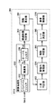
図2に、本実施の形態に係る車両1に搭載されたECU200の機能ブロック図を示す。ECU200は、積算処理部350と、経過時間判定部358と、回数算出部360と、共振判定部362と、駆動力制限部364と、解除判定部366と、レート決定部368と、復帰制御部370とを含む。
FIG. 2 shows a functional block diagram of
積算処理部350は、バンドパスフィルタ352と、積算部354と、ローパスフィルタ356とを含む。
バンドパスフィルタ352は、第2レゾルバ13から取得した回転速度Nm2から共振周波数帯に対応する所定周波数帯の変動成分を第1フィルタ出力値Fo1として抽出する。なお、バンドパスフィルタ352の動作については、周知の技術であるため、その詳細な説明は行なわない。また、共振周波数帯に対応する所定周波数帯は、車両1の種類等によって異なるため、実験的あるいは設計的に適合されればよい。
The
積算部354は、現在の時点以前の所定期間Taにおける、バンドパスフィルタ352によって抽出された第1フィルタ出力値Fo1の絶対値を積算して(時間積分して)積算値Inを算出する。所定期間Taとは、たとえば、変動成分の一周期に対応する時間であることが望ましい。所定期間Taは、一定値に限定されるものではなく、たとえば、第2MG30の回転速度Nm2に応じて変化させるようにしてもよい。ローパスフィルタ356は、積算部354によって算出された積算値Inから所定周波数以上のノイズ成分を除去した第2フィルタ出力値Fo2を算出する。なお、ローパスフィルタの動作については、周知の技術であるため、その詳細な説明は行なわない。なお、ローパスフィルタ356は、省略してもよい。
The integrating
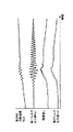
たとえば、第2レゾルバ13から図3の最上段のタイミングチャートのような変化を示す第2MG30の回転速度Nm2が積算処理部350に入力された場合を想定する。
For example, a case is assumed where the rotation speed Nm2 of the
バンドパスフィルタ352は、図3の上から2段目のタイミングチャートに示すように、入力された回転速度Nm2に基づいて共振周波数帯の変動成分を第1フィルタ出力値Fo1として出力する。
As shown in the second timing chart from the top in FIG. 3, the
積算部354は、図3の上から3段目のタイミングチャートに示すように、現在以前の所定期間Taにおける第1フィルタ出力値Fo1の絶対値を積算することによって、積算値Inを算出する。
As shown in the third timing chart from the top in FIG. 3, the integrating
ローパスフィルタ356は、図3の最下段のタイミングチャートに示すように、積算部354によって算出された積算値Inから所定周波数以上のノイズ成分を除去して、第2フィルタ出力値Fo2を出力する。
The low-
経過時間判定部358は、タイマカウント値Ctが初期値Ct(0)(本実施の形態においては、Ct(0)=0)にリセットされてから所定時間Tbが経過したか否かを判定する。すなわち、経過時間判定部358は、タイマカウント値Ctが所定時間Tbに対応する値Ct(1)以上であるか否かを判定する。なお、以下の説明においては、「タイマカウント値Ctを初期値Ct(0)にリセットする」ことを「タイマをクリアする」と記載する。また、本実施の形態において、所定時間Tbは、たとえば、一定値であってもよいし、あるいは、回転速度Nm2から算出される変動成分の1周期であってもよい。
The elapsed
タイマカウント値Ctには、計算サイクル毎に所定値A(本実施の形態においては、A=1)が加算される。なお、経過時間判定部358は、たとえば、タイマがクリアされてから所定時間Tbが経過したと判定した場合に経過判定フラグをオンするようにしてもよい。経過時間判定部358は、タイマカウント値CtがCt(1)以上であると判定した場合に、タイマをクリアする。
A predetermined value A (A = 1 in the present embodiment) is added to the timer count value Ct every calculation cycle. For example, the elapsed
回数算出部360は、第2フィルタ出力値Fo2の所定時間Tbの変化量がしきい値αよりも大きくなる回数を増加傾向を示す値として算出する。
The
具体的には、回数算出部360は、経過時間判定部358においてタイマクリアから所定時間Tbが経過したと判定される毎に、その時点における第2フィルタ出力値(以下、今回の第2フィルタ出力値と記載する)Fo2と、所定時間Tb前の第2フィルタ出力値(以下、前回の第2フィルタ出力値と記載する)Fo2’との出力差Fo2−Fo2’がしきい値α以上であるか否かを判定する。しきい値αは、正の値であって、かつ、第2フィルタ出力値Fo2が増加傾向にあるか否かを判定するための値である。
Specifically, every time the elapsed
回数算出部360は、出力差Fo2−Fo2’がしきい値α以上である場合には、増加カウント値Ciに所定値B(本実施の形態においては、B=1)を加算して、加算された値を増加傾向を示す回数として算出する。
When the output difference Fo2−Fo2 ′ is greater than or equal to the threshold value α, the
回数算出部360は、出力差Fo2−Fo2’がしきい値αよりも小さい場合には、増加カウント値Ciを初期値Ci(0)(本実施の形態においては、Ci(0)=0)にリセットする。
When the output difference Fo2−Fo2 ′ is smaller than the threshold value α, the
たとえば、積算処理部350によって、図4の上段のタイミングチャートに示す第2フィルタ出力値が算出された場合を想定する。図4の中段のタイミングチャートに示すように、所定時間Tbが経過する毎にタイマがクリアされる。 For example, it is assumed that the second filter output value shown in the upper timing chart of FIG. As shown in the middle timing chart of FIG. 4, the timer is cleared every time a predetermined time Tb elapses.
たとえば、時間T(1)にて、経過時間判定部358が所定時間Tbが経過したと判定した場合、回数算出部360は、時間T(1)における第2フィルタ出力値Fo2(1)と、時間T(1)の所定時間Tb前の時間T(0)における第2フィルタ出力値Fo2(0)との出力差Fo2(1)−Fo2(0)を算出する。回数算出部360は、出力差Fo2(1)−Fo2(0)がしきい値α以上である場合に、現在の増加カウント値Ciに所定値B(=1)を加算する。
For example, when the elapsed
時間T(2)にて、経過時間判定部358が再び所定時間Tbが経過したと判定した場合、回数算出部360は、時間T(2)における第2フィルタ出力値Fo2(2)と、時間T(2)の所定時間Tb前の時間T(1)における第2フィルタ出力値Fo2(1)との出力差Fo2(2)−Fo2(1)を算出する。回数算出部360は、出力差Fo2(2)−Fo2(1)がしきい値よりも小さい場合に、増加カウント値Ciを初期値Ci(0)(=0)にリセットする。
When the elapsed
共振判定部362は、第2フィルタ出力値Fo2がしきい値β以上であって、かつ、増加カウント値Ciがしきい値γ以上であるか否かを判定する。なお、共振判定部362は、第2フィルタ出力値Fo2がしきい値β以上であって、かつ、増加カウント値Ciがしきい値γ以上である場合に、共振判定フラグをオン状態にするようにしてもよい。また、共振判定部362は、第2フィルタ出力値Fo2が算出される毎、所定時間Tbが経過する毎に、あるいは、今回の第2フィルタ出力値Fo2と前回の第2フィルタ出力値Fo2’との出力差が算出される毎に、第2フィルタ出力値Fo2がしきい値β以上であって、かつ、増加カウント値Ciがしきい値γ以上であるか否かを判定するようにしてもよい。。しきい値β,γは、いずれも駆動システム84において車両1の悪路走行に起因した共振が発生していることを判定するための値である。
The
駆動力制限部364は、共振判定部362によって第2フィルタ出力値Fo2がしきい値β以上であって、かつ、増加カウント値Ciがしきい値γ以上であると判定された場合に、駆動力の制限制御を実行する。
The driving
駆動力制限部364は、車両1に要求される要求駆動力に対して、通常時の上限値Fd(0)よりも低い値Fd(1)を上限値とした駆動力の制限制御を実行する。通常時の上限値とは、第2フィルタ出力値Fo2がしきい値βよりも低い場合、あるいは、増加カウント値Ciがしきい値γよりも低い場合の要求駆動力の上限値である。
The driving
駆動力制限部364は、要求駆動力が上限値Fd(1)以下である場合には、要求駆動力を最終的な要求駆動力として、車両1(すなわち、第1MG20、第2MG30およびエンジン10)を制御する。駆動力制限部364は、要求駆動力が上限値Fd(1)よりも大きい場合には、Fd(1)を最終的な要求駆動力として車両1を制御する。
When the required driving force is equal to or less than the upper limit value Fd (1), the driving
なお、駆動力制限部364は、たとえば、共振判定フラグがオン状態である場合に駆動力の制限制御を実行するようにしてもよい。また、駆動力制限部364は、第2フィルタ出力値Fo2がしきい値β以上であって、かつ、増加カウント値Ciがしきい値γ以上であると判定された時点で駆動力の制限制御を実行するようにしてもよいし、あるいは、第2フィルタ出力値Fo2がしきい値β以上であって、かつ、増加カウント値Ciがしきい値γ以上であると判定された時点から要求駆動力の上限値を時間の経過とともにFd(1)に近づくように変化させるようにしてもよい。上限値の変化の態様としては、時間の経過に対して線形に変化させてもよいし、非線形に変化させてもよい。
For example, the driving
解除判定部366は、駆動力の制限制御の実行時に、第2フィルタ出力値Fo2がしきい値δ以下であるか否かを判定する。しきい値δは、しきい値β以下の値であれば、特に限定されるものではない。なお、解除判定部366は、たとえば、共振判定フラグがオン状態である場合に、第2フィルタ出力値Fo2がしきい値δ以下であるか否かを判定し、第2フィルタ出力値Fo2がしきい値δ以下である場合に、解除判定フラグをオンするようにしてもよい。
The
レート決定部368は、解除判定部366において第2フィルタ出力値Fo2がしきい値δ以下であると判定された場合に、第2フィルタ出力値Fo2とマップ等とを用いて駆動力の復帰時における復帰レートを決定する。復帰レートとは、駆動力の制限制御からの復帰時に、要求駆動力の上限値をFd(1)からFd(0)に変化させる際の変化特性を規定する値である。
When the
本実施の形態においては、レート決定部368は、たとえば、時間の経過とともに要求駆動力の上限値の変化量が増加していくように復帰レートを決定してもよいし、時間の経過とともに要求駆動力の上限値の変化量が減少していくように復帰レートを決定してもよいし、あるいは、時間の経過に関わらず一定の値を復帰レートとして決定してもよい。レート決定部368は、第2フィルタ出力値Fo2と復帰レート(一定値あるいは変化量)との関係が規定されたマップ、数式あるいは表等から復帰レートを決定する。
In the present embodiment, for example,
復帰制御部370は、解除判定部366において第2フィルタ出力値Fo2がしきい値δ以下であると判定された場合に、レート決定部368によって決定された復帰レートに基づいて駆動力の復帰制御を実行する。
When the
復帰制御部370は、解除判定部366によって第2フィルタ出力値Fo2がしきい値δ以下であると判定された場合に、要求駆動力の上限値をFd(1)からFd(0)まで復帰レートに従って時間の経過とともに変化させる。復帰制御部370は、要求駆動力の上限値がFd(0)まで復帰した場合に上限値Fd(0)を維持する。
The
なお、復帰制御部370は、解除判定部366において第2フィルタ出力値Fo2がしきい値δ以下であると判定された時点に駆動力の復帰制御を開始するようにしてもよいし、あるいは、第2フィルタ出力値Fo2がしきい値δ以下であると判定された時点から所定時間の経過後に駆動力の復帰制御を開始するようにしてもよい。
The
本実施の形態において、積算処理部350と、経過時間判定部358と、回数算出部360と、共振判定部362と、駆動力制限部364と、解除判定部366と、レート決定部368と、復帰制御部370とは、いずれもECU200のCPUがメモリに記憶されたプログラムを実行することにより実現される、ソフトウェアとして機能するものとして説明するが、ハードウェアにより実現されるようにしてもよい。なお、このようなプログラムは記憶媒体に記録されて車両に搭載される。
In the present embodiment, an
図5を参照して、本実施の形態に係る車両に搭載されたECU200で実行される、第2フィルタ出力値Fo2に応じて駆動力を制限するプログラムの制御構造について説明する。
With reference to FIG. 5, a control structure of a program that limits the driving force in accordance with second filter output value Fo2 executed by
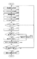
ステップ(以下、ステップをSと記載する)100にて、ECU200は、第2MG30の回転速度Nm2を第2レゾルバ13から取得する。S102にて、ECU200は、取得した回転速度Nm2に対してバンドパスフィルタ処理を実行する。すなわち、ECU200は、回転速度Nm2に基づいて共振周波数帯の変動成分に対応する第1フィルタ出力値Fo1を算出する。
In step (hereinafter, step is referred to as S) 100,
S104にて、ECU200は、積算値算出処理を実行する。すなわち、ECU200は、現在の時点以前の所定期間Taにおける第1フィルタ出力値Fo1の絶対値を積算して積算値Inを算出する。S106にて、ECU200は、積算値Inに対してローパスフィルタ処理を実行する。すなわち、ECU200は、積算値Inに基づいて所定周波数以上のノイズ成分を除去した第2フィルタ出力値Fo2を算出する。
In S104,
S108にて、ECU200は、タイマカウント値Ctに「1」を加算する。S110にて、ECU200は、タイマカウント値Ctが所定時間Tbに対応する値Ct(1)以上であるか否かを判定する。タイマカウント値Ctが所定時間Tbに対応する値Ct(1)以上である場合(S110にてYES)、処理はS112に移される。もしそうでない場合(S110にてNO)、処理はS100に戻される。S112にて、ECU200は、タイマカウント値Ctを初期値「0」にリセットして、タイマをクリアする。
In S108,
S114にて、ECU200は、今回の第2フィルタ出力値Fo2と所定時間Tb前の前回の第2フィルタ出力値Fo2’との出力差Fo2−Fo2’がしきい値α以上であるか否かを判定する。出力差Fo2−Fo2’がしきい値α以上である場合(S114にてYES)、処理はS116に移される。もしそうでない場合(S114にてNO)、処理はS118に移される。
In S114,
S116にて、ECU200は、増加カウント値Ciに「1」を加算する。S118にて、ECU200は、増加カウント値Ciを初期値「0」にリセットする。S120にて、ECU200は、今回の第2フィルタ出力値Fo2をメモリに保存する。なお、保存した今回の第2フィルタ出力値Fo2は、次回の(すなわち、所定時間Tb経過後の)出力差の算出時において「前回の第2フィルタ出力値Fo2’」として用いられる。
In S116,
S122にて、ECU200は、第2フィルタ出力値Fo2がしきい値β以上であって、かつ、増加カウント値Ciがしきい値γ以上であるか否かを判定する。第2フィルタ出力値Fo2がしきい値β以上であって、かつ、増加カウント値Ciがしきい値γ以上である場合(S122にてYES)、処理はS124に移される。もしそうでない場合(S122にてNO)、処理はS100に戻される。S122にて、ECU200は、駆動力の制限制御を実行する。
In S122,
次に、図6を参照して、本実施の形態に係る車両に搭載されたECU200で実行される、第2フィルタ出力値Fo2に応じて駆動力を制限するプログラムの制御構造について説明する。
Next, with reference to FIG. 6, a control structure of a program that limits the driving force according to the second filter output value Fo2 executed by the
S200にて、ECU200は、駆動力の制限時であるか否か、すなわち、駆動力の制限制御が実行中であるか否かを判定する。駆動力の制限時である場合(S200にてYES)、処理はS202に移される。もしそうでない場合(S200にてNO)、処理はS200に戻される。
In S200,
S202にて、ECU200は、第2フィルタ出力値Fo2がしきい値δ以下であるか否かを判定する。第2フィルタ出力値Fo2がしきい値δ以下である場合(S202にてYES)、処理はS204に移される。もしそうでない場合(S202にてNO)、処理はS200に移される。
In S202,
S204にて、ECU200は、第2フィルタ出力値Fo2とマップとを用いて復帰レートを決定する。復帰レートの決定方法については、上述したとおりであり、その詳細な説明は繰り返さない。S206にて、ECU200は、決定された復帰レートに従って、駆動力の復帰制御を実行する。
In S204,
以上のような構造およびフローチャートに基づく本実施の形態に係る車両1に搭載されたECU200の動作について図7−図9を用いて説明する。
The operation of
たとえば、車両1が走行している場合を想定する。このとき、第2MG30の回転速度Nm2が取得され(S100)、取得された第2MG30の回転速度Nm2に対してバンドパスフィルタ処理が実行されることによって共振周波数帯の変動成分に対応する第1フィルタ出力値Fo1が算出される(S100)。さらに、算出された第1フィルタ出力値Fo1に基づいて所定期間Taにおける積算値Inが算出される(S104)。算出された積算値Inに対してローパスフィルタ処理が実行されることによって所定周波数以上のノイズ成分が除去された第2フィルタ出力値Fo2が算出される(S106)。
For example, it is assumed that the
タイマカウント値Ctには、計算サイクル毎に「1」ずつ加算され(S108)、所定時間Tbが経過する毎に(S110にてYES)、タイマがクリアされるとともに(S112)、今回の第2フィルタ出力値Fo2と、所定時間Tb前の前回の第2フィルタ出力値Fo2’との出力差Fo2−Fo2’としきい値αとの比較が行なわれる(S114)。出力差Fo2−Fo2’がしきい値α以上である場合には(S114にてYES)、増加カウント値Ciに「1」が加算される(S116)。 The timer count value Ct is incremented by “1” every calculation cycle (S108), and whenever the predetermined time Tb elapses (YES in S110), the timer is cleared (S112), The output difference Fo2−Fo2 ′ between the filter output value Fo2 and the previous second filter output value Fo2 ′ before the predetermined time Tb is compared with the threshold value α (S114). If output difference Fo2−Fo2 ′ is greater than or equal to threshold value α (YES in S114), “1” is added to increase count value Ci (S116).
<車両の悪路走行に起因した共振が発生した場合>
車両1が悪路で走行している場合において、駆動輪80が、スリップ状態とグリップ状態とを繰り返して、駆動システム84において共振が発生する場合を想定する。このとき、第2MG30の回転速度Nm2の共振周波数帯において回転変動が生じる。そのため、図7に示すように、第2フィルタ出力値Fo2は、時間の経過とともに増加していく。出力差Fo2−Fo2’がしきい値α以上である場合には(S114にてYES)、増加カウント値Ciには、「1」が加算される(S116)。
<When resonance occurs due to driving on a rough road>
When the
共振が発生した場合には、共振周波数帯においての回転変動が継続的に生じるため、出力差Fo2−Fo2’がしきい値α以上となる状態が継続する。その結果、増加カウント値Ciは、時間の経過とともに増加していくこととなる。 When resonance occurs, rotation fluctuations in the resonance frequency band continuously occur, and thus the state where the output difference Fo2−Fo2 ′ is equal to or greater than the threshold value α continues. As a result, the increase count value Ci increases with the passage of time.
時間T(3)にて、増加カウント値Ciがしきい値γ以上となる場合、第2フィルタ出力値Fo2がしきい値βよりも小さいため(S122にてNO)、駆動力の制限制御は実行されない。一方、時間T(4)にて、増加カウント値Ciがしきい値γ以上となる場合であって、かつ、第2フィルタ出力値Fo2がしきい値β以上となる場合には(S122にてYES)、駆動力の制限制御が実行される(S124)。 When increase count value Ci is equal to or greater than threshold value γ at time T (3), second filter output value Fo2 is smaller than threshold value β (NO in S122), so that drive force limiting control is performed. Not executed. On the other hand, when increase count value Ci is equal to or greater than threshold value γ at time T (4) and second filter output value Fo2 is equal to or greater than threshold value β (in S122). YES), driving force limiting control is executed (S124).
駆動力の制限制御が実行されることによって、要求駆動力の上限値がFd(0)からFd(1)に低下するため、車両1の駆動力は低下する傾向にある。そのため、駆動輪80のスリップ状態とグリップ状態とを繰り返す状態が抑制されるため、共振の発生が抑制される。その結果、駆動システム84において共振による過大な入力が抑制されるため、部品の保護が図られる。
When the driving force limit control is executed, the upper limit value of the required driving force decreases from Fd (0) to Fd (1), and thus the driving force of the
<車両に単発的な振動が発生した場合>
車両1に単発的な振動が発生した場合には、図8に示すように、共振周波数帯においても回転変動が生じる。しかしながら、単発的な振動が発生した場合には、共振が発生した場合よりも共振周波数帯の回転変動は、一時的な発生に留まる。そのため、増加カウント値Ciは、しきい値γ以上となるまでに、出力差Fo2−Fo2’がしきい値αよりも小さくなることによって(S114にてNO)、増加カウント値Ciがクリアされる(S118)。その結果、時間T(5)にて、第2フィルタ出力値Fo2がしきい値β以上となった場合においても、増加カウント値Ciは、しきい値γよりも小さいため(S122にてNO)、駆動力の制限制御は実行されない。
<When a single vibration occurs in the vehicle>
When a single vibration is generated in the
<駆動力の制限制御から復帰する場合>
図9に示すように、たとえば、時間T(6)にて、第2フィルタ出力値Fo2がしきい値β以上となり、増加カウント値Ciもしきい値γ以上となることによって(S122にてYES)、駆動力の制限制御が実行された場合を想定する(S124)。
<When returning from drive force limit control>
As shown in FIG. 9, for example, at time T (6), second filter output value Fo2 becomes equal to or greater than threshold value β and increase count value Ci is also equal to or greater than threshold value γ (YES in S122). Assume that the driving force limiting control is executed (S124).
このとき、要求駆動力の上限値が通常時の上限値Fd(0)からFd(1)に制限されるため、車両1に対する要求駆動力は、時間T(6)の時点から減少を開始し、時間T(7)にて、要求駆動力の上限値は、Fd(1)となる。時間T(7)よりも後においては、要求駆動力の上限値としてFd(1)が維持される。
At this time, since the upper limit value of the required driving force is limited to the normal upper limit value Fd (0) to Fd (1), the required driving force with respect to the
要求駆動力の上限値が通常時よりも減少することによって、車両1の駆動力は減少することとなる。その結果、第2MG30の共振周波数帯での回転変動成分の大きさが減少する。そのため、第2フィルタ出力値Fo2は、減少していくこととなる。
When the upper limit value of the required driving force is reduced as compared with the normal time, the driving force of the
時間T(8)にて、駆動力の制限制御の実行中に(S200にてYES)、第2フィルタ出力値Fo2がしきい値δ以下になる場合(S202にてYES)、復帰レートが決定される(S204)。そして、第2フィルタ出力値Fo2がしきい値δ以下であると判定された時点から所定時間経過後の時間T(9)にて、駆動力の復帰制御が実行される(S206)。 If the second filter output value Fo2 is equal to or less than the threshold value δ (YES in S202) during execution of the driving force limiting control at time T (8) (YES in S200), the return rate is determined. (S204). Then, at the time T (9) after a predetermined time has elapsed from the time when it is determined that the second filter output value Fo2 is equal to or less than the threshold value δ, the driving force return control is executed (S206).
決定された復帰レートにしたがって駆動力の復帰制御が実行される。そのため、要求駆動力の上限値は、Fd(1)からFd(0)に向けて時間が経過するほど上限値の変化量が増加するように変化する。時間T(10)にて、要求駆動力の上限値がFd(0)に復帰した場合には、時間T(10)よりも後においては、要求駆動力の上限値としてFd(0)が維持される。 Drive force return control is executed in accordance with the determined return rate. Therefore, the upper limit value of the required driving force changes so that the amount of change in the upper limit value increases as time elapses from Fd (1) to Fd (0). When the upper limit value of the required driving force returns to Fd (0) at time T (10), Fd (0) is maintained as the upper limit value of the required driving force after time T (10). Is done.
以上のようにして、本実施の形態に係る車両によると、第2MG30の回転速度Nm2に単発的な振動が発生して、一時的に共振周波数帯の回転変動成分の大きさが増加した場合でも、車両の悪路走行に起因した共振が発生したと誤判定することを抑制することができる。また、車両が悪路を走行していると判定された場合には、駆動力の制限制御を実行することによって、駆動システム84の部品の保護が図られる。さらに、復帰レートを第2フィルタ出力値Fo2に応じて決定することによって、悪路から抜けた場合には、すばやく駆動力の上限値を復帰させ、悪路走行の継続中の場合には、駆動力の上限値を徐々に復帰させることができる。このように、車両の走行路面に応じて駆動力を復帰させることができる。したがって、走行路面の誤判定を抑制して、走行路面に応じた駆動力制御を実現する車両および車両用制御方法を提供することができる。
As described above, according to the vehicle according to the present embodiment, even when a single vibration occurs at the rotational speed Nm2 of the
本実施の形態においては、ECU200が第2MG30の回転速度Nm2を用いて第2フィルタ出力値Fo2を算出するとして説明したが、駆動輪80および駆動輪80の回転に連動して回転する部品のうちの少なくともいずれか一方の回転速度を用いて第2フィルタ出力値Fo2を算出すればよく、特に第2MG30の回転速度Nm2を用いることに限定されるものではない。
In the present embodiment, the
また、本実施の形態において、ECU200は、駆動力の制限制御実行時に、通常時の上限値Fd(0)よりも小さいFd(1)を要求駆動力の上限値とするとして説明したが、ECU200は、たとえば、駆動力の制限制御実行時に、要求駆動力に対して1よりも小さい係数を乗算した値を最終的な要求駆動力として車両1を制御するようにしてもよい。
In the present embodiment, the
なお、本実施の形態において、車両1は、ハイブリッド車両であるとして説明したが、特にハイブリッド車両に限定されるものではない。車両1は、たとえば、電気自動車であってもよいし、あるいは、内燃機関のみを動力源とする車両であってもよい。
In the present embodiment, the
今回開示された実施の形態はすべての点で例示であって制限的なものではないと考えられるべきである。本発明の範囲は上記した説明ではなくて特許請求の範囲によって示され、特許請求の範囲と均等の意味および範囲内でのすべての変更が含まれることが意図される。 The embodiment disclosed this time should be considered as illustrative in all points and not restrictive. The scope of the present invention is defined by the terms of the claims, rather than the description above, and is intended to include any modifications within the scope and meaning equivalent to the terms of the claims.
1 車両、10 エンジン、11 エンジン回転速度センサ、12,13 レゾルバ、14 車輪速センサ、16 駆動軸、20,30 MG、40 動力分割装置、58 減速機、60 PCU、62 昇圧コンバータ、64 インバータ、70 メインバッテリ、80 駆動輪、82 ドライブシャフト、84 駆動システム、86 トランスミッション、102 気筒、156 電池温度センサ、158 電流センサ、160 電圧センサ、162 アクセルポジションセンサ、200 ECU、350 積算処理部、352 バンドパスフィルタ、354 積算部、356 ローパスフィルタ、358 経過時間判定部、360 回数算出部、362 共振判定部、364 駆動力制限部、366 解除判定部、368 レート決定部、370 復帰制御部。 1 vehicle, 10 engine, 11 engine rotation speed sensor, 12, 13 resolver, 14 wheel speed sensor, 16 drive shaft, 20, 30 MG, 40 power split device, 58 speed reducer, 60 PCU, 62 boost converter, 64 inverter, 70 main battery, 80 drive wheel, 82 drive shaft, 84 drive system, 86 transmission, 102 cylinder, 156 battery temperature sensor, 158 current sensor, 160 voltage sensor, 162 accelerator position sensor, 200 ECU, 350 integration processing unit, 352 band Pass filter, 354 integrating unit, 356 low-pass filter, 358 elapsed time determining unit, 360 times calculating unit, 362 resonance determining unit, 364 driving force limiting unit, 366 release determining unit, 368 rate determining unit, 370 return control unit
Claims (6)
前記駆動輪および前記駆動輪の回転に連動して回転する部品のうちの少なくともいずれか一方についての回転速度を検出するための検出部と、
前記検出部によって検出された前記回転速度に基づいて前記駆動力を制御するための制御部とを含み、
前記制御部は、前記回転速度の変動成分の大きさが第1しきい値よりも大きい場合であって、かつ、前記変動成分の大きさの増加傾向を示す値が第2しきい値よりも大きい場合には、前記駆動力を制限する、車両。 A drive system including a drive wheel for generating a drive force in a vehicle, an internal combustion engine, and a drive transmission device for mechanically connecting the internal combustion engine and the drive wheel;
A detection unit for detecting a rotation speed of at least one of the drive wheel and a component that rotates in conjunction with the rotation of the drive wheel;
A control unit for controlling the driving force based on the rotation speed detected by the detection unit,
The control unit is a case where the magnitude of the fluctuation component of the rotational speed is greater than a first threshold value, and a value indicating an increasing tendency of the magnitude of the fluctuation component is greater than the second threshold value. If large, the vehicle limits the driving force.
前記制御部は、現在の時点以前の所定期間における前記回転速度の共振周波数帯における前記変動成分を抽出して、抽出された前記変動成分に基づいて前記変動成分の大きさを算出する、請求項1または2に記載の車両。 Each of the first threshold value and the second threshold value is a value for determining that a resonance caused by a rough road traveling of the vehicle is occurring in the drive system,
The control unit extracts the fluctuation component in a resonance frequency band of the rotational speed in a predetermined period before a current time point, and calculates the magnitude of the fluctuation component based on the extracted fluctuation component. The vehicle according to 1 or 2.
前記駆動輪および前記駆動輪の回転に連動して回転する部品のうちの少なくともいずれか一方についての回転速度を検出するステップと、
前記回転速度の変動成分の大きさが第1しきい値よりも大きい場合であって、かつ、前記変動成分の大きさの増加傾向を示す値が第2しきい値よりも大きい場合には、前記車両の前記駆動力を制限するステップとを含む、車両用制御方法。 A vehicle control method for use in a vehicle equipped with a drive system including a drive wheel for generating a drive force, an internal combustion engine, and a drive transmission device for mechanically connecting the internal combustion engine and the drive wheel. There,
Detecting a rotational speed of at least one of the drive wheel and a component that rotates in conjunction with rotation of the drive wheel;
When the magnitude of the fluctuation component of the rotational speed is larger than the first threshold and the value indicating the increasing tendency of the magnitude of the fluctuation component is larger than the second threshold, Limiting the driving force of the vehicle.
Priority Applications (1)
| Application Number | Priority Date | Filing Date | Title |
|---|---|---|---|
| JP2011028821A JP5582056B2 (en) | 2011-02-14 | 2011-02-14 | Vehicle and vehicle control method |
Applications Claiming Priority (1)
| Application Number | Priority Date | Filing Date | Title |
|---|---|---|---|
| JP2011028821A JP5582056B2 (en) | 2011-02-14 | 2011-02-14 | Vehicle and vehicle control method |
Publications (2)
| Publication Number | Publication Date |
|---|---|
| JP2012166676A true JP2012166676A (en) | 2012-09-06 |
| JP5582056B2 JP5582056B2 (en) | 2014-09-03 |
Family
ID=46971257
Family Applications (1)
| Application Number | Title | Priority Date | Filing Date |
|---|---|---|---|
| JP2011028821A Active JP5582056B2 (en) | 2011-02-14 | 2011-02-14 | Vehicle and vehicle control method |
Country Status (1)
| Country | Link |
|---|---|
| JP (1) | JP5582056B2 (en) |
Cited By (5)
| Publication number | Priority date | Publication date | Assignee | Title |
|---|---|---|---|---|
| JP2013208960A (en) * | 2012-03-30 | 2013-10-10 | Denso Corp | Driving force control device |
| JP2016007097A (en) * | 2014-06-20 | 2016-01-14 | トヨタ車体株式会社 | Controller of electric vehicle |
| JP2016094153A (en) * | 2014-11-17 | 2016-05-26 | トヨタ自動車株式会社 | Vehicular drive apparatus |
| JP2021088247A (en) * | 2019-12-03 | 2021-06-10 | トヨタ自動車株式会社 | Driving force control device of vehicle |
| CN113183941A (en) * | 2020-01-10 | 2021-07-30 | 丰田自动车株式会社 | Vehicle control device and input reduction system during wave-shaped road running |
Citations (6)
| Publication number | Priority date | Publication date | Assignee | Title |
|---|---|---|---|---|
| JPH0238174A (en) * | 1988-07-29 | 1990-02-07 | Aisin Seiki Co Ltd | Road surface condition sensor and vehicle level controller |
| JPH07324641A (en) * | 1994-04-07 | 1995-12-12 | Mitsubishi Motors Corp | Driving force control device for vehicle |
| JPH0966825A (en) * | 1995-08-30 | 1997-03-11 | Toyota Motor Corp | Wheel slip control device |
| JP2002200974A (en) * | 2001-11-29 | 2002-07-16 | Toyota Motor Corp | Wheel slip control device |
| JP2008072868A (en) * | 2006-09-15 | 2008-03-27 | Nissan Motor Co Ltd | Motor controller for vehicle |
| JP2008180392A (en) * | 2008-04-14 | 2008-08-07 | Toyota Motor Corp | Road surface condition detector, and control device for continuously variable transmission |
-
2011
- 2011-02-14 JP JP2011028821A patent/JP5582056B2/en active Active
Patent Citations (6)
| Publication number | Priority date | Publication date | Assignee | Title |
|---|---|---|---|---|
| JPH0238174A (en) * | 1988-07-29 | 1990-02-07 | Aisin Seiki Co Ltd | Road surface condition sensor and vehicle level controller |
| JPH07324641A (en) * | 1994-04-07 | 1995-12-12 | Mitsubishi Motors Corp | Driving force control device for vehicle |
| JPH0966825A (en) * | 1995-08-30 | 1997-03-11 | Toyota Motor Corp | Wheel slip control device |
| JP2002200974A (en) * | 2001-11-29 | 2002-07-16 | Toyota Motor Corp | Wheel slip control device |
| JP2008072868A (en) * | 2006-09-15 | 2008-03-27 | Nissan Motor Co Ltd | Motor controller for vehicle |
| JP2008180392A (en) * | 2008-04-14 | 2008-08-07 | Toyota Motor Corp | Road surface condition detector, and control device for continuously variable transmission |
Cited By (10)
| Publication number | Priority date | Publication date | Assignee | Title |
|---|---|---|---|---|
| JP2013208960A (en) * | 2012-03-30 | 2013-10-10 | Denso Corp | Driving force control device |
| JP2016007097A (en) * | 2014-06-20 | 2016-01-14 | トヨタ車体株式会社 | Controller of electric vehicle |
| JP2016094153A (en) * | 2014-11-17 | 2016-05-26 | トヨタ自動車株式会社 | Vehicular drive apparatus |
| JP2021088247A (en) * | 2019-12-03 | 2021-06-10 | トヨタ自動車株式会社 | Driving force control device of vehicle |
| JP7188368B2 (en) | 2019-12-03 | 2022-12-13 | トヨタ自動車株式会社 | Vehicle driving force control device |
| CN113183941A (en) * | 2020-01-10 | 2021-07-30 | 丰田自动车株式会社 | Vehicle control device and input reduction system during wave-shaped road running |
| JP2021110299A (en) * | 2020-01-10 | 2021-08-02 | トヨタ自動車株式会社 | Control device of vehicle and wavy road traveling-time input reduction system |
| US20220266846A1 (en) * | 2020-01-10 | 2022-08-25 | Toyota Jidosha Kabushiki Kaisha | Control device of vehicle and system for reducing input during running on wavy road |
| JP7272281B2 (en) | 2020-01-10 | 2023-05-12 | トヨタ自動車株式会社 | VEHICLE CONTROL DEVICE AND INPUT REDUCTION SYSTEM WHEN RUNNING ON WAVED ROAD |
| US11787433B2 (en) | 2020-01-10 | 2023-10-17 | Toyota Jidosha Kabushiki Kaisha | Control device of vehicle and system for reducing input during running on wavy road |
Also Published As
| Publication number | Publication date |
|---|---|
| JP5582056B2 (en) | 2014-09-03 |
Similar Documents
| Publication | Publication Date | Title |
|---|---|---|
| JP6011541B2 (en) | Charge control device and charge control method | |
| JP5879251B2 (en) | Electric motor drive control device | |
| US9266527B2 (en) | Method and system for setting motor torque for hybrid vehicle | |
| JP5664769B2 (en) | Vehicle and vehicle control method | |
| JP5716823B2 (en) | Deterioration diagnosis method for vehicle and power storage device | |
| JP5949731B2 (en) | Hybrid vehicle | |
| JP5598555B2 (en) | Vehicle and vehicle control method | |
| JP5582056B2 (en) | Vehicle and vehicle control method | |
| JP5928418B2 (en) | vehicle | |
| JP6075018B2 (en) | Electric vehicle control device, electric vehicle including the same, and electric vehicle control method | |
| JP5919434B2 (en) | Internal combustion engine control device and internal combustion engine control method | |
| JP6122958B2 (en) | Power generation control device and power generation control method | |
| US8935030B2 (en) | Vehicle control device | |
| JP2007185986A (en) | Controller for vehicle | |
| WO2012101798A1 (en) | Vehicle, and vehicle control method | |
| JP5765419B2 (en) | Vehicle and vehicle control method | |
| JP5607434B2 (en) | Vehicle control device | |
| JP2012224304A (en) | Damping control device of vehicle | |
| JP6361299B2 (en) | Hybrid vehicle | |
| JP2017094835A (en) | Hybrid-vehicular regenerative electric power volume control system, hybrid vehicle, and hybrid-vehicular regenerative electric power volume control method | |
| JP5728447B2 (en) | Vehicle control device | |
| JP2009023496A (en) | Regenerative control device and hybrid car | |
| JP2016094111A (en) | Hybrid vehicle | |
| JP6269325B2 (en) | Hybrid vehicle | |
| JP5673828B2 (en) | Hybrid vehicle |
Legal Events
| Date | Code | Title | Description |
|---|---|---|---|
| A621 | Written request for application examination |
Free format text: JAPANESE INTERMEDIATE CODE: A621 Effective date: 20131017 |
|
| A977 | Report on retrieval |
Free format text: JAPANESE INTERMEDIATE CODE: A971007 Effective date: 20140529 |
|
| TRDD | Decision of grant or rejection written | ||
| A01 | Written decision to grant a patent or to grant a registration (utility model) |
Free format text: JAPANESE INTERMEDIATE CODE: A01 Effective date: 20140617 |
|
| A61 | First payment of annual fees (during grant procedure) |
Free format text: JAPANESE INTERMEDIATE CODE: A61 Effective date: 20140630 |
|
| R151 | Written notification of patent or utility model registration |
Ref document number: 5582056 Country of ref document: JP Free format text: JAPANESE INTERMEDIATE CODE: R151 |