JP2012166318A - Vehicular glass-processing apparatus - Google Patents
Vehicular glass-processing apparatus Download PDFInfo
- Publication number
- JP2012166318A JP2012166318A JP2011030737A JP2011030737A JP2012166318A JP 2012166318 A JP2012166318 A JP 2012166318A JP 2011030737 A JP2011030737 A JP 2011030737A JP 2011030737 A JP2011030737 A JP 2011030737A JP 2012166318 A JP2012166318 A JP 2012166318A
- Authority
- JP
- Japan
- Prior art keywords
- glass
- vehicle glass
- vehicle
- positioning
- positioning member
- Prior art date
- Legal status (The legal status is an assumption and is not a legal conclusion. Google has not performed a legal analysis and makes no representation as to the accuracy of the status listed.)
- Withdrawn
Links
- 239000011521 glass Substances 0.000 claims abstract description 186
- 238000001514 detection method Methods 0.000 claims abstract description 42
- 239000000853 adhesive Substances 0.000 claims description 14
- 230000001070 adhesive effect Effects 0.000 claims description 13
- 238000000034 method Methods 0.000 abstract description 44
- 238000000576 coating method Methods 0.000 description 7
- 230000000052 comparative effect Effects 0.000 description 5
- 230000003028 elevating effect Effects 0.000 description 4
- 239000011248 coating agent Substances 0.000 description 3
- 238000001035 drying Methods 0.000 description 3
- 238000005286 illumination Methods 0.000 description 3
- 238000001179 sorption measurement Methods 0.000 description 3
- 239000007921 spray Substances 0.000 description 3
- JOYRKODLDBILNP-UHFFFAOYSA-N Ethyl urethane Chemical compound CCOC(N)=O JOYRKODLDBILNP-UHFFFAOYSA-N 0.000 description 2
- 238000005238 degreasing Methods 0.000 description 2
- 238000000465 moulding Methods 0.000 description 2
- PXFBZOLANLWPMH-UHFFFAOYSA-N 16-Epiaffinine Natural products C1C(C2=CC=CC=C2N2)=C2C(=O)CC2C(=CC)CN(C)C1C2CO PXFBZOLANLWPMH-UHFFFAOYSA-N 0.000 description 1
- 238000005516 engineering process Methods 0.000 description 1
- 239000007788 liquid Substances 0.000 description 1
- 238000004904 shortening Methods 0.000 description 1
- 230000009466 transformation Effects 0.000 description 1
Images
Landscapes
- Coating Apparatus (AREA)
- Automatic Assembly (AREA)
- Automobile Manufacture Line, Endless Track Vehicle, Trailer (AREA)
Abstract
Description
本発明は、車両用ガラスの処理装置に関する。 The present invention relates to a vehicle glass processing apparatus.
この種の車両用ガラスの処理装置として、車両用ガラスに接着剤を塗布する処理装置が公知である(特許文献1を参照)。車両用ガラスは、略矩形の平板状部材であり、その周囲にはゴム部材(モール)が取付けられる。
この処理装置は、複数のロボット(第1ロボット,第2ロボット)と、一対の位置決め部材と、複数のスプレーガン(脱脂液ガン,プライマガン,ウレタン等の接着剤ガン)を有する。複数のロボットは、典型的にアーム状の部材であり、車両用ガラスを保持して三次元的に動くことができる。
また位置決め部材は、車両用ガラスを適正な向きに補正する部材であり、中継台と、複数の棒状部材を有する。中継台は、車両用ガラスを載置可能な平板部材であり、第1ロボットと第2ロボットの動作領域が重なる位置(両ロボットの中間位置)に配設される。複数の棒状部材は、中継台を囲むように配置しており、それぞれ中継台に向かって進退する(車両用ガラスに向かって移動する)ことができる。
As this type of vehicle glass processing apparatus, a processing apparatus for applying an adhesive to vehicle glass is known (see Patent Document 1). The glass for vehicles is a substantially rectangular flat plate member, and a rubber member (mall) is attached to the periphery thereof.
This processing apparatus has a plurality of robots (first robot, second robot), a pair of positioning members, and a plurality of spray guns (adhesive guns such as a degreasing liquid gun, a primer gun, and urethane). The plurality of robots are typically arm-shaped members, and can move three-dimensionally while holding the glass for a vehicle.
The positioning member is a member that corrects the vehicle glass in an appropriate direction, and includes a relay stand and a plurality of rod-shaped members. The relay stand is a flat plate member on which vehicle glass can be placed, and is arranged at a position where the operation areas of the first robot and the second robot overlap (intermediate position between both robots). The plurality of rod-shaped members are arranged so as to surround the relay stand, and can move forward and backward toward the relay stand (moves toward the vehicle glass).
公知技術では、車両用ガラスに付属品を取付けたのち、第1ロボットにて車両用ガラスを中継台に移動する。つぎに複数の棒状部材を車両用ガラスに向かって移動させる。そして複数の棒状部材によって車両用ガラスを把持しつつ適正な向きに補正したのち、第1ロボットにて車両用ガラスをスプレーガンに対面させて脱脂及びプライマ処理を行う。
つぎに第2ロボットにて車両用ガラスを別の中継台に移動する。そして別の位置決め部材(棒状部材)にて車両用ガラスを適正な向きに補正したのち、第2ロボットにて車両用ガラスを別のスプレーガンに対面させて、ウレタン等の接着剤を塗布する(車両に取付け可能な状態とする)。
In the known technique, after attaching accessories to the vehicle glass, the vehicle glass is moved to the relay stand by the first robot. Next, a plurality of rod-shaped members are moved toward the vehicle glass. After the vehicle glass is gripped by a plurality of rod-shaped members and corrected in an appropriate direction, the vehicle glass is made to face the spray gun by the first robot, and degreasing and primer processing are performed.
Next, the glass for vehicles is moved to another relay stand by the second robot. Then, after correcting the vehicle glass in an appropriate direction with another positioning member (rod-like member), the second glass is made to face another spray gun with a second robot, and an adhesive such as urethane is applied ( It can be attached to the vehicle).
ところで公知技術では、複数の棒状部材を、中継台(車両用ガラス)を囲むように配置する。このため位置決め部材が場所をとるなどして、装置の大型化及び複雑化を招いていた。
また公知技術では、上述の位置決め時に、車両用ガラスやモールに傷がつかないよう配慮する必要があった。このため複数の棒状部材の移動速度を比較的遅めに設定する必要があり、作業時間の短縮には不向きな構成であった。
本発明は上述の点に鑑みて創案されたものであり、本発明が解決しようとする課題は、よりシンプルな構成によって、車両用ガラスを迅速に処理することにある。
By the way, in a well-known technique, a some rod-shaped member is arrange | positioned so that a relay stand (vehicle glass) may be enclosed. For this reason, the positioning member has taken up space, and the apparatus has been increased in size and complexity.
Further, in the known technology, it is necessary to consider that the vehicle glass and the molding are not damaged during the positioning described above. For this reason, it is necessary to set the moving speed of the plurality of rod-like members to be relatively slow, which is not suitable for shortening the working time.
The present invention has been made in view of the above points, and a problem to be solved by the present invention is to quickly process glass for a vehicle with a simpler configuration.
上記課題を解決するための手段として、第1発明の車両用ガラスの処理装置では、付属品を取付けた凹状の車両用ガラスを搬送部材上に配置する。そして車両用ガラスの搬送途中に、位置決め部材によって、車両用ガラスを適正な向きに補正しつつ持ち上げたのち、車両用ガラスの表面に接着剤を塗布して車両に取付け可能とする。
この種の処理装置は、よりシンプルな構成によって、車両用ガラスを迅速に処理できることが望ましい。
As means for solving the above problems, in the vehicle glass processing apparatus according to the first aspect of the present invention, the concave vehicle glass to which the accessory is attached is disposed on the conveying member. In the middle of the transportation of the vehicle glass, the vehicle glass is lifted while being corrected in an appropriate direction by the positioning member, and then an adhesive is applied to the surface of the vehicle glass so that it can be attached to the vehicle.
It is desirable for this type of processing apparatus to be able to process vehicle glass quickly with a simpler configuration.
そこで本発明では、上述の位置決め部材が、検出部材と、検出部材の検出結果に基づいて位置決め部材を移動させる移動部材とを有する。そして位置決め部材の基準点(例えば中心)を搬送部材の基準位置に配置しつつ、位置決め部材を搬送部材上に配置する。ここで検出部材により、車両用ガラスの基準点(例えば中心)と位置決め部材の基準点の双方をそれらの上方から検出可能とする。
そして検出部材が、車両用ガラスの基準点と位置決め部材の基準点がずれていることを検出したとき、移動部材によって位置決め部材を水平方向に移動(スライド移動又は回転移動)させて同ずれを補正したのち(好ましくは予め補正したのち)、車両用ガラスを持ち上げる構成である。
本発明では、位置決め部材を水平方向に移動させる(よりシンプルな)構成で、車両用ガラスの位置決めを迅速に行うことができる。
So, in this invention, the above-mentioned positioning member has a detection member and a moving member which moves a positioning member based on the detection result of a detection member. Then, the positioning member is arranged on the conveying member while the reference point (for example, the center) of the positioning member is arranged at the reference position of the conveying member. Here, the detection member can detect both the reference point (for example, the center) of the vehicle glass and the reference point of the positioning member from above.
When the detection member detects that the reference point of the vehicle glass and the reference point of the positioning member are deviated, the moving member moves the positioning member in the horizontal direction (sliding or rotating) to correct the deviation. After that (preferably after correction in advance), the vehicle glass is lifted.
In the present invention, the positioning of the vehicle glass can be quickly performed with a (simpler) configuration in which the positioning member is moved in the horizontal direction.
第2発明の車両用ガラスの処理装置は、第1発明の車両用ガラスの処理装置であって、上述のように車両用ガラスを持ち上げたのち、検出部材が、車両用ガラスの基準点と搬送部材の基準位置がずれていることを検出する。そこで移動部材によって、位置決め部材とともに車両用ガラスを水平方向に移動させて同ずれを補正する構成とした。
本発明によれば、位置決め部材が、車両用ガラスとともに水平方向に移動することで、車両用ガラスの基準点を搬送部材の基準位置に合わせることができる。
The processing apparatus for glass for vehicles of 2nd invention is a processing apparatus for glass for vehicles of 1st invention, Comprising: After raising glass for vehicles as mentioned above, a detection member carries with the reference point of glass for vehicles, and conveyance It is detected that the reference position of the member is shifted. Therefore, the moving glass is used to move the vehicle glass together with the positioning member in the horizontal direction to correct the deviation.
According to the present invention, the reference point of the vehicle glass can be adjusted to the reference position of the transport member by moving the positioning member in the horizontal direction together with the vehicle glass.
本発明に係る第1発明によれば、よりシンプルな構成によって、車両用ガラスを迅速に処理することができる。また第2発明によれば、より正確に、車両用ガラスを迅速に処理することができる。 According to the 1st invention concerning the present invention, glass for vehicles can be processed quickly with a simpler configuration. According to the second invention, the vehicle glass can be processed more accurately and quickly.
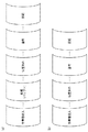
以下、本発明を実施するための形態を、図1〜図11を参照して説明する。各図には、適宜、処理装置及び各部材前方に符号F、処理装置及び各部材後方に符号B、処理装置及び各部材上方に符号UP、処理装置及び各部材下方に符号DWを付す。 Hereinafter, embodiments for carrying out the present invention will be described with reference to FIGS. In each drawing, reference numeral F is attached to the front of the processing apparatus and each member, reference numeral B is attached to the rear of the processing apparatus and each member, reference numeral UP is attached above the processing apparatus and each member, and reference numeral DW is attached below the processing apparatus and each member.
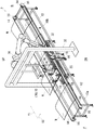
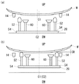
車両用ガラスの処理装置2は、車両用ガラスWに接着剤を塗布するための装置であり、搬送部材10a,10bと、位置決め部材20と、塗布部材30と、支持部材35を有する(図1〜図3を参照、各部材の詳細は後述)。
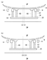
車両用ガラスWは、凹状のガラス(正面視で略矩形状)であり、接着剤の塗布により車両の窓枠(図示省略)に取付け可能となる。ここで車両用ガラスWとして、車両前部の車両用ガラスWや、車両後部の車両用ガラスWを例示できる。車両後部の車両用ガラスWには、車両前部の車両用ガラスWよりも多くの付属品(図示省略)が取付けられる。なお車両用ガラスWの周囲には、図示しないゴム部材(モール)が取付けられる。
The vehicle
The vehicle glass W is a concave glass (substantially rectangular in front view) and can be attached to a vehicle window frame (not shown) by application of an adhesive. Examples of the vehicle glass W include a vehicle glass W at the front of the vehicle and a vehicle glass W at the rear of the vehicle. More accessories (not shown) are attached to the vehicle glass W at the rear of the vehicle than the vehicle glass W at the front of the vehicle. A rubber member (mall) (not shown) is attached around the vehicle glass W.
本実施形態では、複数の車両用ガラスWに付属品を取付けたのち、搬送部材10a,10b上に順次配置する。つぎに各車両用ガラスWの搬送途中に、位置決め部材20によって、車両用ガラスWを適正な向きに補正しつつ上方に持ち上げる。そして車両用ガラスWの周縁に、塗布部材30にて接着剤を塗布して車両(図示省略)に取付け可能とする。
この種の処理装置2は、よりシンプルな構成によって、車両用ガラスWを迅速に処理できることが望ましい。そこで本実施形態では、後述のシンプルな構成により、車両用ガラスWを迅速に処理することとした。以下、各構成について詳述する。
In this embodiment, after attaching accessories to the plurality of vehicle glasses W, they are sequentially arranged on the conveying
It is desirable that this type of
[搬送部材]
搬送部材10a,10b(コンベア状の部材)は、基台12と、一対の無端状ベルト14と、搬送駆動部16と、一対のレール部材18を有する(図1〜図3を参照)。
基台12は、略直方体状の枠体(側面視で長方形状)である。また搬送駆動部16は、無端状ベルト14を駆動させる部材(滑車状)であり、基台12の上部頂点に各々取付けることができる。
そして一対の無端状ベルト14を、基台12の両側に取付けて対面状に配置する。各無端状ベルト14は、車両用ガラスWの搬送方向(搬送方向Y1)に並列する一対の搬送駆動部16間に巻回すことができる。
[Conveying member]
The
The
A pair of
本実施形態では、一対の搬送部材10a,10bを搬送方向Y1に並列配置する(図1を参照)。そして一対の搬送部材10a,10bの間に支持部材35を配置して、後述の塗布部材30と位置決め部材20を配設する。支持部材35は、略アーチ状の部材であり、後述の検出部材70と塗布部材30を支持することができる。
さらに一対のレール部材18を、両搬送部材10a,10bにまたがるように搬送部材10の下部位置に配設する。一対のレール部材18は、支持部材35の下部を通過しつつ、第一の搬送部材10aの途中(後述の検出部72直下)から第二の搬送部材10bの途中(後述の塗布部材30直下)まで配設することができる。
In this embodiment, a pair of
Further, a pair of
[位置決め部材]
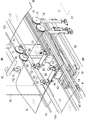
位置決め部材20は、移動部材40と、昇降部材50と、吸着部材60と、検出部材70を有する(図2〜図4を参照)。
本実施形態では、位置決め部材20を、一対のレール部材18(車両用ガラスWの下方)に配置して搬送方向Y1に移動可能とする。このとき位置決め部材20の基準点(中心C2)を、搬送部材10の基準位置(位置C3)に適宜配置できる(図8を参照)。
[Positioning member]
The positioning
In the present embodiment, the positioning
(移動部材)
移動部材40は、位置決め部材20を水平方向に移動(スライド移動又は回転移動)させる部材である(図3を参照)。
そして移動部材40は、複数の平板部(40b,40f,40s)と、複数の駆動部(42f,42s)と、一対のレール部44を有する。複数の平板部はいずれも平板状の部材であり、略矩形の基本平板部40b(最も大寸)と、長方形状の第一平板部40fと、長方形状の第二平板部40sを有する。
(Moving member)
The moving
The moving
本実施形態では、基本平板部40bを、一対のレール部材18上に摺動可能に配設して搬送方向Y1に移動可能とする。つぎに一対のレール部44を、同搬送方向Y1に直交する向き(直交方向X1)で基本平板部40b上に配設する。そして一対のレール部44上に第一平板部40fを摺動可能に配置しつつ、第一駆動部42fによって直交方向X1に移動可能とする(車両用ガラスWのスライド移動を可能とする)。
つぎに第一平板部40f上に第二平板部40sを配置する。そして第二平板部40sを、第二駆動部42sによって第一平板部40fに対して水平方向に相対回転可能に支持する(車両用ガラスWの回転移動を可能とする)。
In the present embodiment, the basic
Next, the second
(昇降部材・吸着部材)
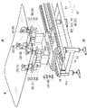
昇降部材50は、車両用ガラスWを昇降させるための部材であり、一対のガラス受部52と、支持部54と、昇降駆動部56を有する(図3を参照)。一対のガラス受部52は、その一端に弾性部を有する棒状部材である。
また吸着部材60は、その一端がラッパ状(パッド)の筒状部材であり、車両用ガラスWを吸引(吸着)できる。
本実施形態では、長方形状の支持部54(平板状)を直交方向X1に向けて、第二平板部40sの端部に配置するとともに、昇降駆動部56によって第二平板部40sに対して昇降可能に保持する。また支持部54の両端にガラス受部52を立設して、その一端側を車両用ガラスWに向ける。さらに支持部54の両側(ガラス受部52の内側)に吸着部材60を立設して、その一端側を車両用ガラスWに向ける。
(Elevating member / Adsorbing member)
The elevating
The
In the present embodiment, the rectangular support portion 54 (flat plate shape) is disposed at the end of the second
(検出部材)
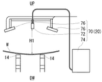
検出部材70は、各部材の基準点(中心C1,中心C2)及び基準位置(C3)を検出する部材である(図3〜図5を参照)。
そして検出部材70は、検出部72(典型的にカメラ)と、指示部74と、照明部76を有する(図4を参照)。指示部74は、検出部72の検出結果(画像処理の結果など)を基にして、移動部材40の移動を支持する部材であり、汎用のコンピュータを使用することができる。
本実施形態では、支持部材35に検出部72を配置して、車両用ガラスWの上方に位置させる(高さH1)。このとき一対の照明部76を、それぞれ検出部72の側方に配置して車両用ガラスWを上方から照らすことが望ましい。そして検出部72によって、車両用ガラスWの基準点(中心C1)と位置決め部材20の基準点(中心C2)の双方を検出する。つぎに各基準点にずれがある場合には、検出部72の検出結果を指示部74に送るとともに、指示部74の指示によって移動部材40が移動する構成とする。
さらに検出部72は、各部材の基準点(中心C1,中心C2)と搬送部材10の基準位置C3のズレを検出することもできる。
(Detection member)
The
And the
In this embodiment, the
Furthermore, the
[塗布部材]
塗布部材30は、先端部に吐出口32を有し、車両用ガラスWに接着剤を吐出可能な部材(アーム状)である(図1を参照)。本実施形態の塗布部材30は、複数の関節部により、吐出口32を三次元的に動かすことができる。
そして本実施形態では、車両用ガラスWを所定の向きで位置決めしておくことで、塗布部材30によって、車両用ガラスWの適切な位置(周縁)に接着剤を塗布できる。このとき塗布部材30は、予め設定されたプログラムにより、所定の決められた動作を行うことができる。例えば塗布部材30は、搬送部材10の基準位置C3を基準として、車両用ガラスWの周縁に沿って移動しつつ接着剤を塗布する動作を行うことができる。
[Coating member]
The
In the present embodiment, the adhesive can be applied to an appropriate position (periphery) of the vehicle glass W by the
[車両用ガラスの処理作業]
車両用ガラスWの処理作業は、投入工程と、位置決め工程と、塗布工程と、反転工程を有する(図9(b)を参照)。なお本実施形態においては、位置決め工程と塗布工程の間に、再位置決め工程を行うことがある(図8を参照)。
本実施形態の投入工程では、車両用ガラスWに各種付属品を取付けたのち、搬送部材10上に配置する。ここで処理装置2には、車両前部の車両用ガラスWを投入することもでき、車両後部の車両用ガラスWを投入することもできる。
[Vehicle glass processing]
The processing operation of the vehicle glass W includes a charging process, a positioning process, a coating process, and a reversing process (see FIG. 9B). In this embodiment, a repositioning process may be performed between the positioning process and the coating process (see FIG. 8).
In the charging process of the present embodiment, various accessories are attached to the vehicle glass W and then placed on the conveying
ところで車両後部の車両用ガラスWは、上述のとおり、車両前部の車両用ガラスWよりも多くの付属品が取付けられる。このため従来、車両前部の車両用ガラスWと車両後部の車両用ガラスWの総処理時間を合わせるため、投入工程と位置決め工程の間に乾燥(バッファ)工程を設ける必要があった(図9(a)を参照)。
これとは異なり本実施形態では、車両後部の車両用ガラスWの位置決め工程(後述)を迅速に行うことができる。このため乾燥(バッファ)工程を省略しつつ、車両前部の車両用ガラスWと車両後部の車両用ガラスWの総処理時間を合わせることができる(図9(b)及び図10を参照)。
By the way, as described above, the vehicle glass W at the rear of the vehicle is attached with more accessories than the vehicle glass W at the front of the vehicle. Therefore, conventionally, in order to match the total processing time of the vehicle glass W at the front of the vehicle and the vehicle glass W at the rear of the vehicle, it is necessary to provide a drying (buffer) process between the charging process and the positioning process (FIG. 9). (See (a)).
Unlike this, in this embodiment, the positioning step (described later) of the vehicle glass W at the rear of the vehicle can be performed quickly. Therefore, the total processing time of the vehicle glass W at the front of the vehicle and the vehicle glass W at the rear of the vehicle can be matched while omitting the drying (buffer) step (see FIGS. 9B and 10).
(位置決め工程)
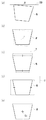
位置決め工程では、位置決め部材20によって、搬送途中の車両用ガラスWを適正な向きに補正する(図4〜図6及び図9(b)を参照)。
このとき検出部72によって、車両用ガラスWの中心C1(基準点)と、位置決め部材20の中心C2(基準点)がずれているかどうかを上方から検出する。つぎに指示部74が、車両用ガラスWの中心C1の座標と、位置決め部材20の中心C2の座標を画像処理(詳細後述)にて認識する。
このように検出部材70が、両部材の座標が異なるかどうかを検出することで、車両用ガラスWの基準点と位置決め部材20の基準点が水平方向にずれていること(いわゆる平面ズレ)を検出できる。そして平面ズレが発生した場合、移動部材40によって位置決め部材20を水平方向に移動(スライド移動又は回転移動)させて同ずれ(平面ズレ量)を補正する。
なお同工程時においては、位置決め部材20を、車両用ガラスWが直下に来る前に補正させ移動させることもできる。こうすることで位置決め工程(特に車両後部の車両用ガラスWの位置決め工程)を迅速に行うことができる。
(Positioning process)
In the positioning step, the vehicle glass W being conveyed is corrected to an appropriate direction by the positioning member 20 (see FIGS. 4 to 6 and FIG. 9B).
At this time, the
In this way, the
In the same step, the positioning
(画像処理)
ここで検出部材70の検出手法(画像処理)を詳述する(図7を参照)。
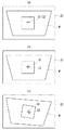
本実施形態では、検出部材70にて車両用ガラスWの外形一部を検出して、車両用ガラスWの傾き(角度θ)を画像水平線D0から算出する。そして車両用ガラスWの外形一部を水平に、アフィン変換を行う。
つぎに車両用ガラスWのx方向の中点を算出するとともに、車両用ガラスWのy方向の中点を算出する。これらx方向の中点とy方向の中点から、車両用ガラスWの中心C1の座標を算出することができる。
(Image processing)
Here, a detection method (image processing) of the
In the present embodiment, a part of the outer shape of the vehicle glass W is detected by the
Next, the midpoint of the vehicle glass W in the x direction is calculated, and the midpoint of the vehicle glass W in the y direction is calculated. From the midpoint of the x direction and the midpoint of the y direction, the coordinates of the center C1 of the vehicle glass W can be calculated.
つぎに図5(b)を参照して、昇降部材50にて車両用ガラスW(適正な向きに補正済)を上方に持ち上げる。そして吸着部材60にて車両用ガラスWを吸着することにより、位置決め部材20に車両用ガラスWを保持することができる(図8を参照)。
このように車両用ガラスWを適正な向きに位置合わせしたのち、位置決め部材20とともに搬送して塗布部材30の下方に移動させる(図1を参照)。つぎに塗布部材30により、車両用ガラスWの周縁に接着剤を塗布したのち(塗布工程ののち)、車両用ガラスWを反転して(反転工程により)車両に取付け可能とする。
Next, with reference to FIG.5 (b), the glass W for vehicles (correct | amended by the appropriate direction) is lifted upwards with the raising / lowering
After the vehicle glass W is thus aligned in an appropriate direction, it is transported together with the positioning
(再位置決め工程)
ところで位置決め工程後に、車両用ガラスWと位置決め部材20との間に角度ズレによるスキ残りCRが生じることがある(図5(b)を参照)。
例えば投入工程時に、搬送部材10に対して車両用ガラスWが直交方向X1にずれたとする。この状態で車両用ガラスWを上方に持ち上げると、角度ズレによるスキ残りCRが生じるとともに、車両用ガラスWの倒れによる位置ズレが発生する。このため車両用ガラスWの中心C1が搬送部材10上の基準位置C3からずれることがある。
そこで本実施形態では、車両用ガラスWを上方に持ち上げたのち、検出部材70によって、車両用ガラスWの中心C1と搬送部材10の基準位置C3がずれているかどうかを再度検出する。
そして倒れによる位置ズレが発生した場合、車両用ガラスWを、位置決め部材20とともに水平方向に移動させて同位置ズレを再補正する(図8を参照)。このように位置決め部材20が、車両用ガラスWとともに水平方向に移動することで、車両用ガラスWの中心C1(基準点)を搬送部材10上の基準位置C3に合わせることができる。
(Repositioning process)
By the way, after the positioning process, there may be a residual CR due to an angular deviation between the vehicle glass W and the positioning member 20 (see FIG. 5B).
For example, it is assumed that the vehicle glass W is displaced in the orthogonal direction X <b> 1 with respect to the conveying
Therefore, in the present embodiment, after the vehicle glass W is lifted upward, the
And when the position shift by a fall generate | occur | produces, the glass W for vehicles is moved to the horizontal direction with the positioning
以上説明したとおり本実施形態では、位置決め部材20を水平方向に移動させる(比較的シンプルな)構成で、車両用ガラスWの位置決めを迅速に行うことができる。そして位置決め部材20により車両用ガラスWを持ち上げることで、車両用ガラスWやモールに傷がつかないよう配慮する必要が極力ない構成となる。
また本実施形態では、位置決め部材20の大部分を車両用ガラスWの下方に配置できるため、公知技術の構成(車両用ガラスの周囲に配置する構成)と比較して装置のコンパクト化を図ることができる。
そして本実施形態では、乾燥(バッファ)工程を省略するなどして、車両用ガラスWの処理工程を簡略化することができる。
このため本実施形態によれば、よりシンプルな構成によって、車両用ガラスWを迅速に処理することができる。
As described above, in the present embodiment, the positioning of the vehicle glass W can be performed quickly with a (relatively simple) configuration in which the
Moreover, in this embodiment, since
In this embodiment, the process of processing the vehicle glass W can be simplified by omitting the drying (buffer) process.
For this reason, according to this embodiment, the glass W for vehicles can be processed rapidly by a simpler structure.
[実施例]
以下、本実施形態を実施例に基づいて説明するが、本発明は実施例に限定されない。
本実施例では、図1の処理装置を用いて車両用ガラスWを処理した。このとき支持部材35に検出部72を配置して、車両用ガラスWの上方に位置させた(高さH1:2000mm)。
本実施例では、車両用ガラスWの中心に紙を張り、その中心箇所に十字印(C1)をつけた(図6を参照)。また車両用ガラスWの十字印(C1)の座標を、検出部材70(画像処理装置)にも中心箇所と認識させた。そして車両用ガラスWを任意の位置に移動させ、車両用ガラスWの十字印を、検出部材70の認識するC1位置から移動させた(意識的に水平ズレを生じさせた)。このときのズレ量は、典型的に±0.3mm〜0.5mmの範囲に設定した。
[Example]
Hereinafter, although this embodiment is described based on an example, the present invention is not limited to the example.
In this example, the vehicle glass W was processed using the processing apparatus of FIG. At this time, the
In this example, paper was stretched at the center of the vehicle glass W, and a cross mark (C1) was added at the center (see FIG. 6). In addition, the coordinates of the cross mark (C1) of the vehicle glass W were also recognized as the central location by the detection member 70 (image processing apparatus). Then, the vehicle glass W was moved to an arbitrary position, and the cross mark of the vehicle glass W was moved from the C1 position recognized by the detection member 70 (consciously generated horizontal deviation). The amount of deviation at this time was typically set in a range of ± 0.3 mm to 0.5 mm.
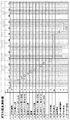
そして本実施例では、複数の車両用ガラスWを順次処理した(図1及び図10を参照)。このとき位置決め工程では、図10の「1ガラス搬送」〜「7位置補正」までの作業を行った。また塗布工程では、図10の「8ガラス塗布」〜「13ガラス払い出し」までの作業を行った。
ここで本実施例では、図10の「1ガラス搬送」及び「2カメラ映像+補正値演算」を予め行ったのち、位置決め工程において、図10の「3ガラス受け上昇」〜「7位置補正」を行った。すなわち第一の車両用ガラスWに対して、「3ガラス受け上昇」〜「7位置補正」を行う間に、第二の車両用ガラスWに対して「1ガラス搬送」及び「2カメラ映像+補正値演算」を(予め)行った。このように本実施例では、処理工程の一部を予め行うことで、車両用ガラスWの処理を迅速に行うことができた。
In this example, a plurality of vehicle glasses W were sequentially processed (see FIGS. 1 and 10). At this time, in the positioning step, the operations from “1 glass conveyance” to “7 position correction” in FIG. 10 were performed. In the coating process, the operations from “8 glass coating” to “13 glass dispensing” in FIG. 10 were performed.
In this embodiment, after “1 glass conveyance” and “2 camera image + correction value calculation” in FIG. 10 are performed in advance, in the positioning step, “3 glass receiving rise” to “7 position correction” in FIG. Went. That is, while performing “3 glass receiving rise” to “7 position correction” for the first vehicle glass W, “1 glass conveyance” and “2 camera image + “Correction value calculation” was performed (in advance). Thus, in the present Example, the processing of the vehicle glass W was able to be performed rapidly by performing a part of processing process previously.
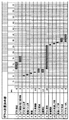
[比較例]
比較例では、図1の処理装置において、公知技術に類似した構成の位置決め部材を使用した(図11を参照)。この位置決め部材は、複数の棒状部材(センタリングローラ)と、昇降部材と、吸着部材を有する。複数の棒状部材(センタリングローラ)は、車両用ガラスWの周囲に配置して、同ガラスに向かって進退可能である。
より詳しくは、複数の棒状部材(センタリングローラ)は、支持部材に昇降可能に取付けられており、車両用ガラスWに向かって下降する(H方向に移動する)。そして複数の棒状部材は、車両用ガラスWに向かって下降したのち、車両用ガラスに向かって進退する(W方向に移動する)。
本比較例の位置決め工程では、図11の「1ガラス搬送」〜「12ガラス受渡し」までの作業を行った。また塗布工程では、図11の「13ガラス塗布」〜「17ローダー返送」までの作業を行った。
そして比較例の構成では、車両用ガラスに傷などがつかないように複数の棒状部材(センタリングローラ)の移動に時間をかける必要があったため、工程完了まで時間がかかった。また上述の構成を順番通りに行う必要があるため(工程一部を予め行うことができないため)位置決め工程に比較的時間がかかった。
[Comparative example]
In the comparative example, a positioning member having a configuration similar to that of a known technique was used in the processing apparatus of FIG. 1 (see FIG. 11). The positioning member includes a plurality of rod-shaped members (centering rollers), a lifting member, and an adsorption member. The plurality of rod-shaped members (centering rollers) are arranged around the vehicle glass W and can advance and retreat toward the glass.
More specifically, the plurality of rod-like members (centering rollers) are attached to the support member so as to be movable up and down, and descend toward the vehicle glass W (move in the H direction). The plurality of rod-shaped members descend toward the vehicle glass W and then move forward and backward toward the vehicle glass (moves in the W direction).
In the positioning process of this comparative example, the operations from “1 glass conveyance” to “12 glass delivery” in FIG. 11 were performed. In the coating process, the operations from “13 glass coating” to “17 loader return” in FIG. 11 were performed.
And in the structure of the comparative example, since it was necessary to take time for the movement of a some rod-shaped member (centering roller) so that the glass for vehicles might not be damaged, it took time to complete the process. Further, since the above-described configuration needs to be performed in order (part of the process cannot be performed in advance), the positioning process takes a relatively long time.
本実施形態の車両用ガラスの処理装置は、上述した実施形態に限定されるものではなく、その他各種の実施形態を取り得る。
(1)本実施形態では、支持部材に他の検出部材を取付けることができる。例えば他の検出部材にて、車両用ガラスを水平方向から検知して接着剤の塗布量を検出することで、車両用ガラスに適正量の接着剤が塗布されたかどうかを検出することができる。
(2)本実施形態では、車両用ガラスが適正位置にある場合には、位置決め部材を移動させることなく、車両用ガラスを持ち上げることができる。
(3)本実施形態における車両用ガラスの基準点と位置決め部材の基準点は、それら部材の中心の他、適宜適当な部位に設定することができる。
The vehicle glass processing apparatus of the present embodiment is not limited to the above-described embodiment, and can take other various embodiments.
(1) In this embodiment, another detection member can be attached to the support member. For example, it is possible to detect whether or not an appropriate amount of adhesive has been applied to the vehicle glass by detecting the glass for the vehicle from the horizontal direction and detecting the application amount of the adhesive with another detection member.
(2) In this embodiment, when the vehicle glass is in an appropriate position, the vehicle glass can be lifted without moving the positioning member.
(3) The reference point of the vehicle glass and the reference point of the positioning member in the present embodiment can be set as appropriate in addition to the center of these members.
2 処理装置
10a,10b 搬送部材
12 基台
14 無端状ベルト
16 搬送駆動部
18 レール部材
20 位置決め部材
30 塗布部材
32 吐出口
34 関節部
35 支持部材
40b 基本平板部
40 移動部材
40f 第一平板部
40s 第二平板部
42f 第一駆動部
42s 第二駆動部
44 レール部
50 昇降部材
52 ガラス受部
54 支持部
56 昇降駆動部
60 吸着部材
70 検出部材
72 検出部
74 指示部
76 照明部
2
Claims (2)
前記位置決め部材が、検出部材と、前記検出部材の検出結果に基づいて前記位置決め部材を移動させる移動部材とを有し、
前記位置決め部材の基準点を前記搬送部材の基準位置に配置しつつ、前記位置決め部材を前記搬送部材上に配置するとともに、前記検出部材によって、前記車両用ガラスの基準点と前記位置決め部材の基準点の双方をそれらの上方から検出可能とし、
前記検出部材が、前記車両用ガラスの基準点と前記位置決め部材の基準点がずれていることを検出したとき、前記移動部材によって前記位置決め部材を水平方向に移動させて同ずれを補正したのち、前記車両用ガラスを持ち上げる構成である車両用ガラスの処理装置。 A concave vehicle glass attached with an accessory is arranged on a conveying member, and the vehicle glass is lifted while correcting the vehicle glass in an appropriate direction by a positioning member during the conveyance of the vehicle glass. In the processing apparatus for vehicle glass that can be attached to the vehicle by applying an adhesive to the surface of the vehicle glass,
The positioning member includes a detection member and a moving member that moves the positioning member based on a detection result of the detection member;
While positioning the reference point of the positioning member at the reference position of the conveying member, the positioning member is disposed on the conveying member, and the reference point of the vehicle glass and the reference point of the positioning member are determined by the detection member. Both of them can be detected from above,
When the detection member detects that the reference point of the vehicle glass is shifted from the reference point of the positioning member, the moving member moves the positioning member in the horizontal direction and corrects the shift. The processing apparatus of the glass for vehicles which is the structure which lifts the said glass for vehicles.
前記車両用ガラスを持ち上げたのち、前記検出部材が、前記車両用ガラスの基準点と前記搬送部材の基準位置がずれていることを検出したとき、前記移動部材によって、前記位置決め部材とともに前記車両用ガラスを水平方向に移動させて同ずれを補正する構成である車両用ガラスの処理装置。
In the processing apparatus of the glass for vehicles of Claim 1,
After the vehicle glass is lifted, when the detection member detects that a reference point of the vehicle glass is shifted from a reference position of the transport member, the moving member and the positioning member are used together with the positioning member. A processing apparatus for glass for a vehicle, which is configured to correct the deviation by moving the glass in a horizontal direction.
Priority Applications (1)
| Application Number | Priority Date | Filing Date | Title |
|---|---|---|---|
| JP2011030737A JP2012166318A (en) | 2011-02-16 | 2011-02-16 | Vehicular glass-processing apparatus |
Applications Claiming Priority (1)
| Application Number | Priority Date | Filing Date | Title |
|---|---|---|---|
| JP2011030737A JP2012166318A (en) | 2011-02-16 | 2011-02-16 | Vehicular glass-processing apparatus |
Publications (1)
| Publication Number | Publication Date |
|---|---|
| JP2012166318A true JP2012166318A (en) | 2012-09-06 |
Family
ID=46970989
Family Applications (1)
| Application Number | Title | Priority Date | Filing Date |
|---|---|---|---|
| JP2011030737A Withdrawn JP2012166318A (en) | 2011-02-16 | 2011-02-16 | Vehicular glass-processing apparatus |
Country Status (1)
| Country | Link |
|---|---|
| JP (1) | JP2012166318A (en) |
Cited By (6)
| Publication number | Priority date | Publication date | Assignee | Title |
|---|---|---|---|---|
| JP2015196106A (en) * | 2014-03-31 | 2015-11-09 | 芝浦メカトロニクス株式会社 | Coating liquid coating apparatus and method |
| US9443717B2 (en) | 2014-07-16 | 2016-09-13 | Hirata Corporation | Conveyance system and conveyance method |
| CN111168347A (en) * | 2020-03-10 | 2020-05-19 | 杨浩 | Automatic assembling equipment for toothed plate of automobile glass lifter |
| JP2022516104A (en) * | 2019-03-11 | 2022-02-24 | 広汽本田汽車有限公司 | Adhesive application system for automobile windshields |
| CN114682449A (en) * | 2022-05-09 | 2022-07-01 | 中国第一汽车股份有限公司 | Integrated gluing table for overturning and rotating vehicle glass |
| CN118597644A (en) * | 2024-06-20 | 2024-09-06 | 山东华世力自动化科技有限公司 | A glass original sheet shuttle bin fetching machine control method and locking device thereof |
-
2011
- 2011-02-16 JP JP2011030737A patent/JP2012166318A/en not_active Withdrawn
Cited By (8)
| Publication number | Priority date | Publication date | Assignee | Title |
|---|---|---|---|---|
| JP2015196106A (en) * | 2014-03-31 | 2015-11-09 | 芝浦メカトロニクス株式会社 | Coating liquid coating apparatus and method |
| US9443717B2 (en) | 2014-07-16 | 2016-09-13 | Hirata Corporation | Conveyance system and conveyance method |
| JP2022516104A (en) * | 2019-03-11 | 2022-02-24 | 広汽本田汽車有限公司 | Adhesive application system for automobile windshields |
| JP7224473B2 (en) | 2019-03-11 | 2023-02-17 | 広汽本田汽車有限公司 | Automotive Windshield Adhesive Dispensing System |
| CN111168347A (en) * | 2020-03-10 | 2020-05-19 | 杨浩 | Automatic assembling equipment for toothed plate of automobile glass lifter |
| CN111168347B (en) * | 2020-03-10 | 2021-07-20 | 瑞安市汉宇汽车部件有限公司 | Automatic assembling equipment for toothed plate of automobile glass lifter |
| CN114682449A (en) * | 2022-05-09 | 2022-07-01 | 中国第一汽车股份有限公司 | Integrated gluing table for overturning and rotating vehicle glass |
| CN118597644A (en) * | 2024-06-20 | 2024-09-06 | 山东华世力自动化科技有限公司 | A glass original sheet shuttle bin fetching machine control method and locking device thereof |
Similar Documents
| Publication | Publication Date | Title |
|---|---|---|
| JP2012166318A (en) | Vehicular glass-processing apparatus | |
| CN102099272B (en) | Glass substrate packaging device and glass substrate packaging method | |
| CN112850145B (en) | Curved surface screen crack check out test set | |
| US11124366B2 (en) | Inspection apparatus for display panel and testing method for display panel | |
| CN101407283B (en) | Substrate conveying device | |
| TW201336762A (en) | Glass substrate transport device and transport method | |
| CN102105375A (en) | Apparatus and method for transferring board-like work | |
| CN104755396A (en) | Method and device for conveying large-area panels of extreme size | |
| CN102169253B (en) | Liquid crystal substrate bonding system | |
| CN107709014A (en) | Printing equipment and to base board operation device | |
| JP2009249091A (en) | Plate work reversing device | |
| WO2018003573A1 (en) | Conveyance system | |
| CN212845080U (en) | Article inspection device | |
| TW201314827A (en) | Carrying vehicle | |
| JP5512349B2 (en) | Substrate inversion apparatus and substrate inversion method | |
| JP3955576B2 (en) | Liquid crystal panel automatic gripping apparatus and method | |
| TW201804565A (en) | Robot, robot control method, teaching tool, and robot teaching method | |
| CN210972999U (en) | Glass plate manufacturing equipment | |
| CN221643839U (en) | Sheet turning machine and glass cutting equipment | |
| JP2018010273A (en) | Alignment device | |
| KR20150068575A (en) | Board grip and carrying device and method for using thereof | |
| JP2005017386A (en) | Flat work inspection and correction equipment | |
| JP2007099466A5 (en) | ||
| CN109585611A (en) | A kind of battery strings composition method and the battery strings type-setting machine using this method | |
| JP2014170871A (en) | Component mounting device and component mounting system |
Legal Events
| Date | Code | Title | Description |
|---|---|---|---|
| A300 | Withdrawal of application because of no request for examination |
Free format text: JAPANESE INTERMEDIATE CODE: A300 Effective date: 20140513 |