JP2012163575A - Distance measuring device - Google Patents
Distance measuring device Download PDFInfo
- Publication number
- JP2012163575A JP2012163575A JP2012104404A JP2012104404A JP2012163575A JP 2012163575 A JP2012163575 A JP 2012163575A JP 2012104404 A JP2012104404 A JP 2012104404A JP 2012104404 A JP2012104404 A JP 2012104404A JP 2012163575 A JP2012163575 A JP 2012163575A
- Authority
- JP
- Japan
- Prior art keywords
- pulse
- aircraft
- interrogation pulse
- waveform
- converter
- Prior art date
- Legal status (The legal status is an assumption and is not a legal conclusion. Google has not performed a legal analysis and makes no representation as to the accuracy of the status listed.)
- Abandoned
Links
Images

Landscapes
- Radar Systems Or Details Thereof (AREA)
Abstract
Description
本発明は、航空機が位置を把握するために航空機との間で送受信する際、パルスを補正する距離測定装置に関する。 The present invention relates to a distance measuring device that corrects a pulse when an aircraft transmits and receives to and from an aircraft in order to grasp a position.
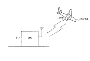
航空機では様々な方法で位置を検出しながら飛行を行なうが、航空機と地上局間の距離を距離測定装置(DME:Distance Measuring Equipment)を利用して測定し、航空機の位置を把握することがある(例えば、非特許文献1参照)。図4に示すように、距離測定装置1は地上局に設置される装置であり、航空機2から送信されるパルスを受信すると、受信したパルスに応答するパルスを航空機2に送信する。航空機2では、このパルスの送受信を利用して、距離測定装置1(地上局)との距離を測定し、飛行している位置を把握することができる。
Aircraft fly while detecting the position using various methods, but the distance between the aircraft and the ground station may be measured by using a distance measuring device (DME) to determine the position of the aircraft. (For example, refer nonpatent literature 1). As shown in FIG. 4, the distance measuring device 1 is a device installed in the ground station. When a pulse transmitted from the
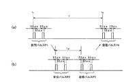
具体的には、図5に示すように、航空機2は、距離測定装置1に質問パルスP1を送信する。この質問パルスP1はパルス幅が3.5μsのツインパルスであり、国際的に運用モード毎のパルス間隔や遅延間隔等が規定されている。また、パルスに利用する周波数は、DME毎に異なる値が設定されている。図5に一例を示すパルスは、パルス間隔が12μsであるDME/Nの運用モードである。
Specifically, as shown in FIG. 5, the
航空機2から送信された質問パルスP1を受信した距離測定装置1は、質問パルスP1を受信して決められた時間(Td)の経過後、航空機2に対して質問パルスP1に応答する応答パルスP2を送信する。DME/Nモードの場合、この応答パルスP2もパルス幅が3.5μsで、パルス間隔が12μsである。
The distance measuring device 1 that has received the interrogation pulse P1 transmitted from the
航空機2は、距離測定装置1から送信された応答パルスP2として受信する。応答パルスP2を受信した航空機2は、質問パルスP1の送信時刻t1および応答パルスP2の受信時刻t2とから求められる応答時間Tと、電波(信号)の伝送速度とに基づいて、距離測定装置1から航空機2までの距離を測定している。
The
従来の距離測定装置1と航空機2では、受信するパルスP1,P2の検出に、パルス幅を利用している(例えば、特許文献1参照)。すなわち、所定のパルス幅及びパルス間隔で特定できるパルスを受信したとき、距離測定の為に送受信されるパルスであると判定し、処理を実行している。
In the conventional distance measuring device 1 and the
実際に距離測定装置1や航空機2で送受信される各パルスは、アナログ信号であるが、距離測定装置1におけるアナログ回路の経年変化により歪みが生じる問題がある。パルスが受けた歪みの影響を補正することが望ましいが、アナログ信号をアナログ回路を利用して補正することは困難であった(例えば、特許文献1および2参照)。
Each pulse actually transmitted and received by the distance measuring device 1 or the
上述したように、従来の距離測定装置1では、アナログ回路の経年変化により生じる歪みを補正することが困難であるという問題があった。 As described above, the conventional distance measuring apparatus 1 has a problem that it is difficult to correct distortion caused by aging of the analog circuit.
従って本発明は、パルスに発生した歪みを容易に補正する距離測定装置を提供する。 Therefore, the present invention provides a distance measuring device that easily corrects distortion generated in a pulse.
航空機から受信した質問パルスと航空機から受信する質問パルスの理想波形とを合成し、アナログ信号に変換するとともに質問パルスの検出用に処理するアナログ回路と、アナログ回路で処理された質問パルスをディジタル信号に変換するA/D変換器と、A/D変換器でディジタル信号に変換された質問パルスと航空機から受信する質問パルスの理想波形との差分を利用して、アナログ回路で質問パルスに生じた歪みを補正した新たな質問パルスを生成する補正実行部とを備える。 The interrogation pulse received from the aircraft and the ideal waveform of the interrogation pulse received from the aircraft are combined and converted to an analog signal, and the analog pulse processed for detection of the interrogation pulse, and the interrogation pulse processed by the analog circuit are converted into a digital signal An analog circuit generates an interrogation pulse by using the difference between the A / D converter that converts the signal to the digital signal and the interrogation pulse that is converted into a digital signal by the A / D converter and the ideal waveform of the interrogation pulse that is received from the aircraft. A correction execution unit that generates a new interrogation pulse in which distortion is corrected.
本発明によれば、パルスに発生した歪みを容易に補正することができる。 According to the present invention, distortion generated in a pulse can be easily corrected.
図1乃至図3を用いて本発明の最良の実施形態に係る距離測定装置(DME)1について説明する。 A distance measuring device (DME) 1 according to the best embodiment of the present invention will be described with reference to FIGS.
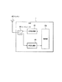
距離測定装置1は、送信処理部10、受信処理部20、サーキュレータ30、アンテナ40及び制御部50を備えている。送信処理部10は制御部50から入力するパルス送信トリガに従って応答パルス(ツインパルス)を生成し、生成した応答パルスをサーキュレータ30およびアンテナ40を介して航空機2に送信する。また、アンテナ40が質問パルス(ツインパルス)を受信すると、サーキュレータ30を介して受信処理部20に質問パルスを出力し、受信処理部20はこの質問パルスの処理結果を制御部50に出力する。
The distance measuring device 1 includes a
制御部50は、受信処理部20から入力する質問パルスに応じて、応答パルスを送信するタイミングを決定し、決定したタイミングで応答パルスが送信されるように送信処理部10にパルス送信トリガを出力する。応答パルスの送信のタイミングは、距離測定装置1で航空機2から質問パルスを受信してから応答パルスを送信するまでの時間として定められている時間に応じて決定される。
The
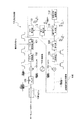
〈送信処理部〉
まず、図2を参照して送信処理部10について説明する。この送信処理部10は、航空機2に送信する応答パルスをアナログ信号に変換して送信用に処理するD/A変換器102、ミキサ104およびRFアンプ105等のアナログ回路で応答パルスに生じた歪みを逆方向に補正して新たな応答パルスを生成する送信信号補正処理部100を備えている。この新たな応答パルスは、アナログ回路で生じる歪みに対して逆方向に補正されているため、アナログ回路で処理された後に歪みのないパルス波形になり、歪みのない応答パルスを航空機に送信することができる。
<Transmission processing section>
First, the
パルス波形出力部101は、制御部50からパルス送信用トリガを入力すると、補正処理部100のIFFT実行部113から入力する応答パルスのパルス波形をD/A変換器102に出力する。ここで、パルス波形出力部101が出力するパルス波形は、D/A変換器102、ミキサ104およびRFアンプ105によって与えられる歪みが補正実行部113で逆補正された波形である。
When a pulse transmission trigger is input from the
D/A変換器102は、パルス波形出力部102から入力するパルス波形をアナログ信号からディジタル信号に変換し、ミキサ104に出力する。このD/A変換器102は、アナログ回路であるため、経年変化が生じる。したがって、D/A変換器102から出力されるパルス波形には、歪みが含まれることがある。
The D /
発振器103は、距離測定装置1で定められているチャネル周波数(例えば、1GHz)のRF信号をミキサ104とミキサ107に出力する。
The oscillator 103 outputs an RF signal having a channel frequency (for example, 1 GHz) determined by the distance measuring device 1 to the
ミキサ104は、D/A変換器102から入力するパルス波形と発振器103から入力するRF信号の周波数とをアップコンバートしてパルス波形を変調し、RF信号となったパルス波形をRFアンプ105に出力する。このミキサ104もD/A変換器102と同様にアナログ回路であるため、ミキサ104から出力されるパルス波形には経年変化によって生じる歪みが含まれることがある。
The
RFアンプ105は、ミキサ104から入力するパルス波形を増幅し、カプラ106に出力する。このRFアンプ105もD/A変換器102およびミキサ104と同様にアナログ回路であるため、RFアンプ105から出力されるパルス波形には経年変化によって生じる歪みが含まれることがある。
The
カプラ106は、RFアンプ105から入力したパルス波形を応答パルスとしてサーキュレータ30に出力し、アンテナ40を介して送信する。また、カプラ106は、RFアンプ105から入力した応答パルスをミキサ107に出力する。この応答パルスは、D/A変換器102、ミキサ104およびRFアンプ105を経ているため、D/A変換器102、ミキサ104およびRFアンプ105で生じた歪みが含まれることがある。
The coupler 106 outputs the pulse waveform input from the
ミキサ107は、カプラ106から入力する応答パルスと発振器103から入力するRF信号の周波数とをダウンコンバートして変調し、A/D変換器108に出力する。
The mixer 107 down-converts and modulates the response pulse input from the coupler 106 and the frequency of the RF signal input from the oscillator 103 and outputs the result to the A /
A/D変換器108は、ミキサ107から入力する応答パルスをアナログ信号からディジタル信号に変換し、FFT実行部109に出力する。すなわち、A/D変換器108は、パルス波形出力部101から出力される波形ではなく、実際に航空機に送信するアナログ回路の歪みを含む応答パルスと同一のパルス波形を入力することができる。
The A /
FFT実行部109は、アナログ回路によるパルス波形の歪みを補正するため、パルス波形をフーリエ変換して応答パルスの周波数成分(周波数スペクトラム)を求め、補正データ生成部110と、補正実行部111に出力する。
The
理想波形記憶部112は、距離測定装置1が送信する応答パルスの理想的なパルス波形の周波数成分(周波数スペクトラム)を記憶している。
The ideal
補正データ生成部110は、理想波形記憶部112から理想的なパルス波形の周波数成分を読み出し、FFT実行部109から入力した周波数成分と比較して各周波数成分の差分を求め、この差分を送信パルスに含まれる歪みを補正する補正データとし、補正実行部111に出力する。
The correction
補正実行部111は、FFT実行部109から入力する応用パルスの周波数成分を、補正データ生成部110で生成された補正データで逆方向に補正し、アナログ回路で応答パルスに加えられた歪みを補正する。また、補正実行部111は、補正後の周波数成分をIFFT実行部113に出力する。
The
IFFT実行部113は、補正後の周波数成分を逆フーリエ変換して時間領域のパルス波形に戻し、補正後のパルス波形を新たな応答パルスとしてパルス波形出力部101に出力する。すなわち、この新たな応答パルスはアナログ回路で発生する歪みが逆補正されているため、この新たな応答パルスを利用すれば、後にアナログ回路での歪みによって理想的なパルス波形に変化する。
The
パルス波形出力部101は、IFFT実行部から入力した新たなパルス波形を歪みに対応するパルス波形として制御部50から入力した出力タイミングに応じて出力する。
The pulse
このように、本発明の実施形態に係る距離測定装置1では、アナログ回路であるD/A変換器102、ミキサ104、RFアンプ105で処理された送信用のパルス波形を送信信号補正処理部100に出力し、この送信信号補正処理部100で記憶している理想波形と比較してアナログ回路で生じる歪みを予め逆方向に補正したパルス波形を送信用のパルス波形として利用している。したがって、距離測定装置1では、アナログ回路で生じる歪みを除くようなパルス波形を生成することで、歪みを含まないパルス波形を送信することができる。
As described above, in the distance measuring apparatus 1 according to the embodiment of the present invention, the transmission pulse waveform processed by the D /
〈受信処理部〉
続いて、図3を参照して受信処理部20について説明する。この受信処理部20は、航空機2から受信する質問パルスをディジタル信号に変換して処理するRFアンプ206、ミキサ207、A/D変換器208等のアナログ回路で質問パルスに生じた歪みを逆方向に補正して質問パルスとする受信信号補正処理部200を備えている。この補正後の新たな質問パルスは、アナログ回路で生じる歪みに対して補正されるため、歪みのない応答パルスとして制御部50に出力することができる。
<Reception processing section>
Next, the
リファレンス波形記憶部201では、距離測定装置1が受信する信号の理想的なパルス波形をリファレンス波形として記憶している。
The reference
D/A変換器202は、リファレンス波形記憶部201で記憶されているリファレンス波形をアナログ信号からディジタル信号に変換し、ミキサ204に出力する。
The D / A converter 202 converts the reference waveform stored in the reference
発振器203は、レーダ1で定められている周波数(例えば、1GHz)のRF信号をミキサ204とミキサ207に出力する。 The oscillator 203 outputs an RF signal having a frequency (for example, 1 GHz) determined by the radar 1 to the mixer 204 and the mixer 207.
ミキサ204は、A/D変換器202から入力するリファレンス波形と発振器203から入力するRF信号の周波数とをアップコンバートしてリファレンス波形を変調し、RF信号となったリファレンス波形をカプラ205に出力する。 The mixer 204 up-converts the reference waveform input from the A / D converter 202 and the frequency of the RF signal input from the oscillator 203 to modulate the reference waveform, and outputs the reference waveform as an RF signal to the coupler 205. .
カプラ205は、サーキュレータ30からアンテナ40で受信した応答パルスのパルス波形を入力する。また、カプラ205は、サーキュレータ30から入力したパルス波形にミキサ204から入力したRF信号のリファレンス波形を混合してRFアンプ206に出力する。
The coupler 205 inputs the pulse waveform of the response pulse received from the
RFアンプ206は、カプラ205から入力したパルス波形を増幅してミキサ207に出力する。このRFアンプ206は、アナログ回路であるため、経年変化が生じる。したがって、RFアンプ206から出力される波形には、歪みが含まれることがある。
The
ミキサ207は、RFアンプ206から入力するパルス波形と発振器203から入力するRF信号の周波数とをダウンコンバートしてパルス波形を変調し、A/D変換器208に出力する。このミキサ207もRFアンプ206と同様にアナログ回路であるため、ミキサ207から出力されるパルス波形には経年変化によって生じる歪みが含まれることがある。
The mixer 207 modulates the pulse waveform by down-converting the pulse waveform input from the
A/D変換器208は、ミキサ207から入力するパルス波形をアナログ信号からディジタル信号に変換し、FFT実行部209に出力する。このA/D変換器208もRFアンプ206およびミキサ207と同様にアナログ回路であるため、RFアンプ105から出力されるパルス波形には経年変化によって生じる歪みが含まれることがある。すなわち、A/D変換器208から出力される質問パルスは、受信した質問パルスにアナログ回路の歪みを含むことがある。
The A /
FFT実行部209は、アナログ回路によるパルス波形の歪みを補正するため、パルス波形をフーリエ変換してパルス波形の周波数成分(周波数スペクトラム)を求め、補正データ生成部211と、補正実行部212に出力する。
In order to correct the distortion of the pulse waveform caused by the analog circuit, the
理想波形記憶部210は、距離測定装置1が受信する信号の理想的なパルス波形の周波数成分(周波数スペクトラム)を記憶している。この周波数成分は、リファレンス波形記憶部201で記憶されているリファレンス波形をフーリエ変換することによって得ることができる。
The ideal
補正データ生成部211は、理想波形記憶部210から理想的なパルス波形の周波数成分を読み出し、FFT実行部209から入力した周波数成分と比較して各周波数成分の差分を求め、この差分を信号に含まれる歪みを補正する補正データとし、補正実行部212に出力する。
The correction
補正実行部212は、FFT実行部209から入力する質問パルスの周波数成分を、補正データ生成部211で生成された補正データで補正し、アナログ回路で質問パルスに加えられた歪みを補正する。また、補正実行部212は、補正後の周波数成分をIFFT実行部213に出力する。
The
IFFT実行部213は、補正後の周波数成分を逆フーリエ変換して時間領域のパルス波形に戻し、この補正後のパルス波形を新たな質問パルスとして制御部50に出力する。すなわち、この補正後の新たな質問パルスはアナログ回路で発生する歪みが補正されているため、この新たな質問パルスを利用すれば、アナログ回路で発生した歪みを含まないパルス波形を利用して航空機2に応答することができる。
The
このように、本発明の実施形態に係る距離測定装置1では、航空機から受信した質問パルスを処理するアナログ回路であるRFアンプ206、ミキサ207、A/D変換器208で処理されたパルス波形を受信信号補正処理部200に出力し、この受信信号補正処理部200で記憶している理想波形と比較してアナログ回路で生じる歪みを補正し、制御部50へ出力している。したがって、距離測定装置1では、アナログ回路で生じる歪みを含まないパルス波形から、質問パルスを判断して航空機に応答することができる。
As described above, in the distance measuring device 1 according to the embodiment of the present invention, the pulse waveforms processed by the
1…距離測定装置
10…送信処理部
101…パルス波形出力部
102…A/D変換器(アナログ回路)
103…発振器
104…ミキサ(アナログ回路)
105…RFアンプ(アナログ回路)
106…カプラ
107…ミキサ
108…D/A変換器
109…FFT実行部
110…補正データ生成部
111…補正実行部
112…理想波形記憶部
113…IFFT実行部
20…受信処理部
201…リファレンス波形記憶部
202…D/A変換器
203…発振器
204…ミキサ
205…カプラ
206…RFアンプ(アナログ回路)
207…ミキサ(アナログ回路)
208…A/D変換器(アナログ回路)
209…FFT実行部
210…理想波形記憶部
211…補正データ生成部
212…FFT実行部
213…IFFT実行部
30…サーキュレータ
40…アンテナ
50…制御部
2…航空機
DESCRIPTION OF SYMBOLS 1 ... Distance measuring
103 ...
105 ... RF amplifier (analog circuit)
DESCRIPTION OF SYMBOLS 106 ... Coupler 107 ...
207 ... Mixer (analog circuit)
208 ... A / D converter (analog circuit)
209:
Claims (2)
航空機から受信した質問パルスと前記航空機から受信する質問パルスの理想波形とを合成し、アナログ信号に変換するとともに質問パルスの検出用に処理するアナログ回路と、
前記アナログ回路で処理された質問パルスをディジタル信号に変換するA/D変換器と、
前記A/D変換器でディジタル信号に変換された質問パルスと航空機から受信する質問パルスの理想波形との差分を利用して、前記アナログ回路で質問パルスに生じた歪みを補正した新たな質問パルスを生成する補正実行部と、
を備えることを特徴とする距離測定装置。 A distance measuring device that receives an interrogation pulse transmitted from an aircraft and transmits a response pulse used to measure the distance from a reference position on the ground in the aircraft,
An analog circuit that synthesizes an interrogation pulse received from an aircraft and an ideal waveform of the interrogation pulse received from the aircraft, converts the analog pulse into an analog signal, and processes the interrogation pulse for detection;
An A / D converter that converts the interrogation pulse processed by the analog circuit into a digital signal;
A new interrogation pulse in which distortion generated in the interrogation pulse is corrected by the analog circuit using a difference between an interrogation pulse converted into a digital signal by the A / D converter and an ideal waveform of the interrogation pulse received from the aircraft A correction execution unit for generating
A distance measuring device comprising:
前記A/D変換器でディジタル信号に変換された時間成分の質問パルスを周波数成分にフーリエ変換するFFT実行部と、
質問パルスの理想波形の周波数成分を記憶する理想波形記憶部と、
前記補正実行部で補正された周波数成分の信号を時間成分の質問パルスに逆フーリエ変換するIFFT実行部と、
を備えることを特徴とする請求項1に記載の距離測定装置。 A reference waveform storage unit for storing a time component of an ideal waveform of an interrogation pulse;
An FFT execution unit that Fourier-transforms the interrogation pulse of the time component converted into a digital signal by the A / D converter into a frequency component;
An ideal waveform storage unit that stores the frequency component of the ideal waveform of the interrogation pulse;
An IFFT execution unit that performs inverse Fourier transform on the frequency component signal corrected by the correction execution unit into a time component interrogation pulse;
The distance measuring device according to claim 1, comprising:
Priority Applications (1)
| Application Number | Priority Date | Filing Date | Title |
|---|---|---|---|
| JP2012104404A JP2012163575A (en) | 2012-05-01 | 2012-05-01 | Distance measuring device |
Applications Claiming Priority (1)
| Application Number | Priority Date | Filing Date | Title |
|---|---|---|---|
| JP2012104404A JP2012163575A (en) | 2012-05-01 | 2012-05-01 | Distance measuring device |
Related Parent Applications (1)
| Application Number | Title | Priority Date | Filing Date |
|---|---|---|---|
| JP2008232010A Division JP2010066097A (en) | 2008-09-10 | 2008-09-10 | Distance measuring apparatus |
Publications (1)
| Publication Number | Publication Date |
|---|---|
| JP2012163575A true JP2012163575A (en) | 2012-08-30 |
Family
ID=46843066
Family Applications (1)
| Application Number | Title | Priority Date | Filing Date |
|---|---|---|---|
| JP2012104404A Abandoned JP2012163575A (en) | 2012-05-01 | 2012-05-01 | Distance measuring device |
Country Status (1)
| Country | Link |
|---|---|
| JP (1) | JP2012163575A (en) |
Citations (5)
| Publication number | Priority date | Publication date | Assignee | Title |
|---|---|---|---|---|
| JPS61154577U (en) * | 1985-03-15 | 1986-09-25 | ||
| JPS63208781A (en) * | 1987-02-24 | 1988-08-30 | Nec Corp | Waveform shaping circuit |
| JPS6426178A (en) * | 1987-07-22 | 1989-01-27 | Toshiba Corp | Transmitter-receiver |
| JP2006042227A (en) * | 2004-07-30 | 2006-02-09 | Nec Network & Sensor Systems Ltd | Automatic pulse waveform shaping system |
| JP2008190955A (en) * | 2007-02-02 | 2008-08-21 | Toshiba Corp | Pulse signal transmitting device, adjusting method of its waveform, and dme ground station device |
-
2012
- 2012-05-01 JP JP2012104404A patent/JP2012163575A/en not_active Abandoned
Patent Citations (5)
| Publication number | Priority date | Publication date | Assignee | Title |
|---|---|---|---|---|
| JPS61154577U (en) * | 1985-03-15 | 1986-09-25 | ||
| JPS63208781A (en) * | 1987-02-24 | 1988-08-30 | Nec Corp | Waveform shaping circuit |
| JPS6426178A (en) * | 1987-07-22 | 1989-01-27 | Toshiba Corp | Transmitter-receiver |
| JP2006042227A (en) * | 2004-07-30 | 2006-02-09 | Nec Network & Sensor Systems Ltd | Automatic pulse waveform shaping system |
| JP2008190955A (en) * | 2007-02-02 | 2008-08-21 | Toshiba Corp | Pulse signal transmitting device, adjusting method of its waveform, and dme ground station device |
Similar Documents
| Publication | Publication Date | Title |
|---|---|---|
| US11057862B2 (en) | Wi-Fi radar detection using synchronized wireless access point | |
| US9448301B2 (en) | Calibrated radar apparatus and associated methods | |
| US10371799B1 (en) | Methods of calibration for radar apparatus | |
| WO2007094266A1 (en) | Distance measuring system | |
| Suksmono et al. | Signal processing of range detection for SFCW radars using Matlab and GNU radio | |
| JP2016156620A (en) | Radar system | |
| JP6376901B2 (en) | Received signal processing device, radar device, and target detection method | |
| JP2013137268A (en) | Fmcw radar system | |
| JP2010066097A (en) | Distance measuring apparatus | |
| JP2008298597A (en) | Dme ground-based apparatus | |
| JP2012163575A (en) | Distance measuring device | |
| CN108226916B (en) | Frequency stepping signal speed compensation system based on difference frequency double waveforms | |
| US9797992B2 (en) | FMCW radar apparatus | |
| DE102011075936A1 (en) | Method and system for determining the time of flight of a signal | |
| JP2010281596A (en) | Temperature-compensated distance detection device | |
| KR101324172B1 (en) | Method and device for toa calibration of multi-channel digital receiver | |
| JP3303862B2 (en) | Pulse compression radar device | |
| EP3617745B1 (en) | Radar device | |
| KR101359344B1 (en) | Distance measuring apparatus based on FMCW | |
| JP2016156732A (en) | Distance measuring equipment and distance measuring method | |
| CN110058203A (en) | For handling the device and method and radar equipment of input signal | |
| JP2007078463A (en) | Monitoring radar system | |
| RU2591049C2 (en) | Pseudocoherent rls with high repetition frequency of sounding pulses | |
| KR101159657B1 (en) | Apparatus for estimating sweep nonlinearity in high range resolution radar seeker | |
| JP2019144082A (en) | Fmcw radar device |
Legal Events
| Date | Code | Title | Description |
|---|---|---|---|
| A131 | Notification of reasons for refusal |
Free format text: JAPANESE INTERMEDIATE CODE: A131 Effective date: 20130702 |
|
| A762 | Written abandonment of application |
Free format text: JAPANESE INTERMEDIATE CODE: A762 Effective date: 20130827 |