JP2012161456A - Wheelchair having detachable main wheel connected by axle - Google Patents
Wheelchair having detachable main wheel connected by axle Download PDFInfo
- Publication number
- JP2012161456A JP2012161456A JP2011023793A JP2011023793A JP2012161456A JP 2012161456 A JP2012161456 A JP 2012161456A JP 2011023793 A JP2011023793 A JP 2011023793A JP 2011023793 A JP2011023793 A JP 2011023793A JP 2012161456 A JP2012161456 A JP 2012161456A
- Authority
- JP
- Japan
- Prior art keywords
- wheelchair
- axle
- armrest
- seat
- diameter
- Prior art date
- Legal status (The legal status is an assumption and is not a legal conclusion. Google has not performed a legal analysis and makes no representation as to the accuracy of the status listed.)
- Granted
Links
Images


Abstract
Description
本願発明は、飛行機、列車等の座席の間の狭い通路を走行できる車椅子に関する。より詳しくは、飛行機、列車等の座席の間の狭い通路を走行できるように、車椅子の大径の主車輪を車軸で連結して着脱自在とし、狭い通路では大径の主車輪を外し、アームレストを折り畳んで車椅子の幅を狭くし、狭い通路を走行できるようにした車椅子に関する。 The present invention relates to a wheelchair that can travel in a narrow passage between seats such as airplanes and trains. More specifically, the large diameter main wheel of the wheelchair is connected by an axle so that it can travel in a narrow passage between seats of airplanes, trains, etc., and the large diameter main wheel is removed in the narrow passage and the armrest It is related with the wheelchair which folded the wheel and made the width of a wheelchair narrow and was able to drive | work a narrow passage.
車椅子の利用者は、乗り物に乗る際に入り口が広く、社内にも広いスペースのある電車等の場合は、駅員の介助の元で乗車することができる。しかし、飛行機や、新幹線のように、入り口も狭く、座席間の通路も狭い乗り物では、通常の車椅子は利用できず、介助者に多大な負担を掛けることになる。そのために、狭い通路でも走行できる車椅子が種々検討されている。 Wheelchair users can ride with the assistance of station staff in the case of trains and the like that have a wide entrance and a large space in the office when riding a vehicle. However, a vehicle with a narrow entrance and a narrow passage between seats, such as an airplane or a bullet train, cannot use a normal wheelchair and places a heavy burden on the assistant. Therefore, various wheelchairs that can travel even in narrow passages have been studied.
特許文献1の請求項1には「車輪着脱機構を介してフレームに着脱自在に軸支されるとともに常には走行面に接地する後輪と、前記フレーム下部に設けられ前記後輪を走行面から離隔した位置へ上昇可能なリフトアップ装置と、を備え、前記リフトアップ装置は、前端部が車椅子のフレーム下部に枢着されて揺動可能に設けられた支持アームと、前記支持アームの自由端部の下部に設けられたリフトアップ車輪と、ペダル部を有し上端部が前記フレーム下部に枢着された第1リンクバーと、下端部が前記支持アームの自由端部に枢着され上端部が前記第1リンクバー下端部に枢着された第2リンクバーと、前記支持アームを前記フレーム下部方向へ回動付勢するばねと、を備え、前記リフトアップ車輪が、前記フレーム下部に接近した非接地位置と走行面に接地した接地位置との間を昇降可能に形成され、該接地位置において前記フレームの高さ位置を上昇可能に形成されてなることを特徴とする車椅子。」が開示されている。 According to claim 1 of Patent Document 1, “a rear wheel that is pivotally supported by the frame via a wheel attaching / detaching mechanism and is always in contact with the running surface, and a rear wheel provided at the lower part of the frame from the running surface. A lift-up device capable of ascending to a separated position, wherein the lift-up device includes a support arm pivotally attached to a lower end of a wheelchair frame, and a free end of the support arm. A lift-up wheel provided at the lower part of the part, a first link bar having a pedal part and having an upper end pivoted to the lower part of the frame, and a lower end pivoted to the free end of the support arm. Includes a second link bar pivotally attached to the lower end of the first link bar, and a spring that urges the support arm to rotate toward the lower part of the frame, and the lift-up wheel approaches the lower part of the frame. Ungrounded A wheelchair characterized in that it is formed so as to be able to move up and down between a grounding position and a grounding position grounded to the traveling surface, and is formed so that the height position of the frame can be raised at the grounding position. .
特許文献2の段落[0005]の課題を解決するための手段には、「本発明は、座部、背も垂れ、アームレスト、フットレストを装着した台座及び台座に装着した小径車輪を設けた車椅子において、前記小径車輪より径が大きく、着脱自在の大径車輪とより構成する、車椅子装置である。また本発明は、前述した車椅子装置において、大径車輪の着脱を行うため、上面形状を傾斜部と水平部とで構成する二本のレールからなるスロープレールを備えたことを特徴とする、車椅子装置である。また本発明は、前述した車椅子装置において、リクライニング機構を有する背も垂れと、前記背も垂れの両側部に設けたレールをスライドする座部とを備えたことを特徴とする、車椅子装置である。さらに本発明は、前述したいずれかの車椅子装置において、台座に対して座部は、少なくとも90度の平面回転を許容するよう構成したことを特徴とする、車椅子装置である。本発明は、前述したいずれかの車椅子装置の利用方法であって、大径車輪を着脱する場合、スロープレールに小径車輪を乗せ、大径車輪が床面に接触しない位置まで車椅子装置を登らせて大径車輪の着脱を行うことを特徴とする、車椅子装置の利用方法である。」と開示されている。 The means for solving the problem of paragraph [0005] of Patent Document 2 includes: “In the wheelchair provided with a seat, a backrest, an armrest, a pedestal with a footrest attached, and a small-diameter wheel attached to the pedestal. The wheelchair device comprises a large-diameter wheel having a diameter larger than that of the small-diameter wheel, and the detachable large-diameter wheel. A wheelchair device comprising a slope rail composed of two rails composed of a horizontal portion and a horizontal portion.In addition, the present invention relates to the above-described wheelchair device, the backrest having a reclining mechanism, A wheelchair device comprising: a seat that slides on rails provided on both sides of the backrest, and the present invention includes any one of the wheelchair devices described above. The wheelchair device is characterized in that the seat portion is configured to allow at least 90 degree plane rotation with respect to the pedestal. Use of a wheelchair device to attach and detach a large-diameter wheel by placing the small-diameter wheel on a slope rail and climbing the wheelchair device to a position where the large-diameter wheel does not contact the floor surface. It is a method. "
特許文献3の段落[0007]の課題を解決するための手段には、「前記の課題を解決するため、請求項1の発明では、シート(座体)と、バックレスト(背もたれ)と、これらを支持する本体枠とを備えた車椅子において、本体枠の左右側部に、屋外用後輪(主輪)及びこれよりも小径の屋内用後輪の対と、屋外用後輪よりも小径の屋外用前輪及び屋内用前輪との対を、それら屋外用前後輪の群と屋内用前後輪の群とを選択的に使用できるように取り付けるという構成にした。」と記載され、
さらに段落[0008]に、「請求項2の発明はより好適な態様であり、この発明は、請求項1において、前記屋外用後輪は本体枠に対して着脱自在である一方、前記屋外用前輪と屋内用前輪とは、左右横長の軸心回りに回動させ得る支持部材に取り付けられており、支持部材の姿勢を変えることによって屋外用前輪と屋内用前輪とを選択的に接地できるようになっている。」と開示されている。
The means for solving the problem of paragraph [0007] of Patent Document 3 includes: “In order to solve the above-mentioned problem, in the invention of claim 1, a seat (seat body), a backrest (backrest), and these In a wheelchair equipped with a main body frame for supporting a pair of outdoor rear wheels (main wheels) and smaller indoor rear wheels, and a smaller diameter than the outdoor rear wheels, on the left and right sides of the main body frame The pair of outdoor front wheels and indoor front wheels is configured to be attached so that the group of outdoor front and rear wheels and the group of indoor front and rear wheels can be selectively used.
Further, in paragraph [0008], “the invention of claim 2 is a more preferable aspect, and in the invention of claim 1, the outdoor rear wheel is detachable from the body frame, while the outdoor The front wheel and the indoor front wheel are attached to a support member that can be rotated around a horizontally long axis, so that the outdoor front wheel and the indoor front wheel can be selectively grounded by changing the posture of the support member. It is disclosed.
上記のように、特許文献1では狭い場所でも走行できるように、大径の後輪を着脱自在にしたのに対し、特許文献2、及び3ではそれぞれ室内では屋外用の後輪を外して、屋外においては屋外用の後輪で走行できるように、後輪を着脱自在にした車椅子が開示されている。しかし、狭い通路を走行するためには、上記の車椅子でも十分ではなく、飛行機や列車の座席間等の狭い通路を走行できる車椅子の出現が望まれている。 As described above, in Patent Document 1, the large-diameter rear wheel is made detachable so that it can run even in a narrow place, whereas in Patent Documents 2 and 3, the outdoor rear wheel is removed indoors, A wheelchair is disclosed in which the rear wheels are detachable so that they can run outdoors with the rear wheels. However, in order to travel in a narrow passage, the above wheelchair is not sufficient, and the appearance of a wheelchair capable of traveling in a narrow passage such as between airplane seats or train seats is desired.
本願発明は、飛行機、列車等の座席の間の狭い通路を走行できる車椅子を提供するものである。より詳しくは、飛行機、列車等の座席の間の狭い通路を走行できるように、通常の車椅子の大径の主車輪を着脱自在にするとともに、座部の両側面に着設されたアームレストを折り畳んで、狭い通路でも走行できる車椅子を提供するものである。 This invention provides the wheelchair which can drive | work the narrow channel | path between seats, such as an airplane and a train. More specifically, the large diameter main wheel of a normal wheelchair is made detachable and the armrests attached to both sides of the seat are folded so that it can travel in a narrow passage between seats of airplanes, trains, etc. Therefore, it provides a wheelchair that can travel even in a narrow passage.
本願発明は上記事実に鑑み、飛行機、列車等の座席の間の狭い通路を走行できるように、通常の車椅子の両側の大径の主車輪を車軸で連結して、着脱自在にするとともに、座部の両側に着設されたアームレストを折り畳んで狭い通路でも走行できる車椅子とした。 In view of the above facts, the present invention makes it possible to connect a large main wheel on both sides of a normal wheelchair with an axle so that it can travel in a narrow passage between seats of airplanes, trains, etc. A wheelchair that can be run in a narrow passage by folding the armrests on both sides of the section.
本発明の特徴は、前部に回動自在の前部キャスターと後部に回動しない後部キャスターを有し、座部と座部の後部に背もたれと、座部の両サイドにタックルブレーキを着設したアームレストを有する車椅子に、車軸で連結された大径の主車輪の前記車軸が着脱自在に軸着された車椅子であって、前記車軸を取り外すと大径の両車輪が取り外されると共に、前記アームレストが折り畳み可能であることを特徴とする車椅子である。大径の主車輪を取り外すと、座部の両側に着設されたアームレストのフレームが回動可能となり、アームレストを回動させることにより、車椅子の幅がさらに狭くなって、新幹線、航空機等の通路を介助者により容易に通行することができる。 The feature of the present invention is that it has a front caster that can rotate at the front and a rear caster that does not rotate at the rear, and a backrest at the rear of the seat and the seat, and tackle brakes on both sides of the seat A wheelchair having a large-diameter main wheel connected by an axle to a wheelchair having an armrest that is detachably mounted, and when the axle is removed, both large-diameter wheels are removed, and the armrest Is a wheelchair characterized by being foldable. When the large-diameter main wheel is removed, the armrest frames attached to both sides of the seat can be turned. By turning the armrest, the width of the wheelchair is further reduced, and the passage of Shinkansen, aircraft, etc. It can be easily passed by an assistant.
本発明の別の特徴は、前記同様に車軸を取り外すと車軸に連結された左右の大径の主車輪が取り外されると共に、前記アームレストが車椅子の背もたれの後方に折り畳み可能となる車椅子である。大径の主車輪を取り外すと、座部の両側に着設されたアームレストのフレームが回動可能となり、アームレストを背もたれの後方に回動させることにより、車椅子の幅がさらに狭くなって、新幹線、航空機の通路を介助者により容易に通行することができる。 Another feature of the present invention is a wheelchair in which the left and right large-diameter main wheels connected to the axle are removed when the axle is removed, and the armrest can be folded behind the backrest of the wheelchair. When the main wheel with large diameter is removed, the frame of the armrest attached on both sides of the seat becomes rotatable, and by turning the armrest to the back of the backrest, the width of the wheelchair is further reduced, the Shinkansen, It can be easily passed by an assistant through an aircraft passage.
本発明の別の特徴は、前記同様に車軸を取り外すと車軸に連結された左右の大径の主車輪が取り外されると共に、前記アームレストが車椅子の座部の下側に折り畳み可能となる車椅子である。大径の主車輪を取り外すと、座部の両側に着設されたアームレストのフレームが座部の下側に回動可能となり、アームレストを座部の下に回動させることにより、車椅子の幅がさらに狭くなって、新幹線、航空機の通路を介助者により容易に通行することができる。 Another feature of the present invention is a wheelchair in which the left and right large-diameter main wheels connected to the axle are removed when the axle is removed, and the armrest can be folded under the seat of the wheelchair. . When the large-diameter main wheel is removed, the armrest frame attached to both sides of the seat can be turned to the lower side of the seat, and the width of the wheelchair can be increased by rotating the armrest under the seat. It becomes even narrower and can be easily passed by an assistant through the Shinkansen and aircraft passages.
本発明の車軸で連結された脱着自在の主車輪を有する車椅子は、大径の主車輪を取り外すと、座部の両側に着設されたアームレストのフレームが回動可能となり、アームレストを回動させることにより、車椅子の幅がさらに狭くなって、新幹線、航空機等の通路を介助者により容易に通行することができる。 In the wheelchair having removable main wheels connected by the axle according to the present invention, when the main wheel having a large diameter is removed, the frame of the armrest attached to both sides of the seat portion becomes rotatable, and the armrest is rotated. As a result, the width of the wheelchair is further narrowed and can be easily passed by the assistant through passages such as Shinkansen and aircraft.
以下に図面を用いて本発明の実施の態様についていくつかの好ましい形態を例示するが、特許請求の範囲に記載された発明の範囲を限定することは意図するものではない。 Several preferred embodiments of the embodiments of the present invention are illustrated below with reference to the drawings, but are not intended to limit the scope of the invention described in the claims.
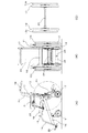
図1(A)に示すように、本願発明の車椅子は、車椅子の下部フレーム16に回動自在の前部キャスター11と後部に回動しない後部キャスター12を着設し、座部19と座部の後部に背もたれ20と、座部19の両サイドにタックルブレーキ22を着設したアームレスト21と前部フレーム14にフットレスト22を有する車椅子に、車軸26で連結された大径の主車輪13の前記車軸26が着脱自在に軸着された車椅子である。該車椅子の後部に着設されたリフトアップレバー24を上げると車軸狭持部27、28が開いて前記車軸26が取り外し可能となる。車軸26を取り外すと車軸26の両側に軸着された大径の主車輪13が取り外されると共に、前記アームレスト21が折り畳み可能となる車椅子である。
As shown in FIG. 1 (A), the wheelchair according to the present invention has a
図1(B)に示すように、本発明の車椅子は前部に回動可能な前部キャスター11と、座部19と座部の後部の背もたれフレーム17に着設された背もたれ20と、座部19の両サイドにアームレスト21とその両側にハンドリム13aを備えた大径の主車輪13が車軸で連結されて着脱自在に軸着された車椅子の後部のリフトアップレバー24部分を示している。図1(B)に示すように、リフトアップレバー24は車椅子の後方に着設されており、介助者がリフトアップレバー24を足で蹴り上げるか、手で持ち上げると上下の車軸狭持部27、28が開いて、車軸の脱抜を可能になるものである。
As shown in FIG. 1 (B), the wheelchair according to the present invention includes a
図1(C)は、車椅子の後部のリフトアップレバー24を介助者が手で持ち上げるか、足で蹴り上げて上下の車軸狭持部27、28を開いて、車椅子から取り外した車軸で連結された左右の大径の主車輪13を示している。
In FIG. 1 (C), the assistant lifts the lift-up
図2(A)は、本発明の車椅子のリフトアップレバー24の部分を示している。脱着可能な左右の主車輪13は車軸26で連結されており、車軸上部狭持部27と車軸下部狭持部28によって上下から挟むようにして狭持されている。車軸上部狭持部27はリフトアップレバー24に連結され、車軸狭持部27、28の開閉を行っている。
FIG. 2A shows a portion of the lift-up
図2(B)は、後部キャスター12に着設されたフットレバー25を踏んで後部キャスター12を固定し、リフトアップレバー24を持ち上げると左右の車軸上部狭持部27が回動して、車軸24が脱抜可能となり、車軸24に連結された左右の主車輪13を取り外すことができる。
FIG. 2B shows that when the
図3(A)は、大径の主車輪13を取り外した車椅子100のアームレスト21を背もたれ20の後方に折り畳んだ側面図を示している。アームレスト21にはタックルブレーキ22が着設されており、タックルブレーキ22もアームレスト21と共に後方に収納される。このようにアームレスト21を後方に折り畳むと、本発明の車椅子100の横幅は400mmとなり、航空機や新幹線等の列車の座席の間の狭い通路を介助者により容易に走行することができる。大径の主車輪を取り外した後の車椅子の横幅は前記の幅に限定されるものではなく、航空機や新幹線等の列車の座席の間の狭い通路を走行できる幅、例えば、350mm〜450mmの幅が望ましい。
FIG. 3A shows a side view in which the
図3(B)は、前部に回動自在のキャスター11と後部の回動しない後部キャスター12を有し、座部19と座部の後部に背もたれ20と、座部の両サイドにアームレスト21を有する車椅子の側面図を示す。本願発明の車椅子100は車軸26で連結された大径の主車輪13は車軸上部狭持部27と車軸下部狭持部28により狭持されている。左右の車軸上部狭持部27に連結されたリフトアップレバー24を持ち上げると左右の車軸上部狭持部27が回動して前記車軸26が取り外し可能となり、車軸26を取り外すことによって車軸に連結された左右の大径の主車輪13が取り外される。左右の大径の主車輪13が取り外されると、左右のアームレスト21は、アームレスト21の軸着部21aから回動可能となり、車椅子の背もたれ20の後部に折り畳むことができる車椅子100である。
FIG. 3 (B) has a
図4(A)は、大径の主車輪13を外した車椅子200のアームレスト21を車椅子の下に折り畳んだ正面図を示している。アームレスト21にはタックルブレーキ22が着設されており、タックルブレーキ22もアームレスト21と共に車椅子の座部19の下部に収納される。このような状態で本願発明の車椅子200の横幅は400mmとなり、航空機や新幹線等の列車の座席の間の狭い通路を介助者により容易に走行することができる。大径の主車輪13を取り外した後の車椅子200の横幅は前記の幅に限定されるものではなく、航空機や新幹線等の列車の座席の間の狭い通路を走行できる幅、例えば、350mm〜450mmの幅が望ましい。
FIG. 4A shows a front view in which the
図4(B)は、前部に回動自在のキャスター11と後部に回動しない後部キャスター12を有し、座部19と座部の後部に背もたれ20と、座部の両サイドにアームレスト21を有する車椅子200の側面図を示す。本発明の車椅子200は車軸26で連結された大径の主車輪13は車軸上部狭持部27と車軸下部狭持部28により狭持されている。左右の車軸上部狭持部27に連結されたリフトアップレバー24を持ち上げると左右の車軸上部狭持部27が回動して前記車軸26が取り外し可能となり、車軸26を取り外すことによって車軸に連結された左右の大径の主車輪13が取り外される。左右の大径の主車輪13が取り外されると、左右のアームレスト21は、アームレスト21の軸着部21aから回動可能となり、車椅子の座部19の下に折り畳むことができる車椅子200である。
FIG. 4 (B) has a
100:脱着可能な大径の主車輪を有する車椅子のアームレストを背もたれの後方に折り畳み可能な車椅子。
200:脱着可能な大径の主車輪を有する車椅子のアームレストを座部の下側に折り畳み可能な車椅子。
11:回動可能な前部キャスター
12:後部キャスター
13:大径の主車輪
14:前部フレーム
15:上部フレーム
16:下部フレーム
17:背もたれフレーム
18:グリップ
19:座部
20:背もたれ
21:アームレスト
22:タックルブレーキ
23:フットレスト
24:リフトアップレバー
25:フットレバー
26:車軸
27:車軸上部狭持部
28:車軸下部狭持部
100: A wheelchair in which an armrest of a wheelchair having a detachable large-diameter main wheel can be folded behind a backrest.
200: A wheelchair in which an armrest of a wheelchair having a detachable large-diameter main wheel can be folded under the seat.
11: Turnable front caster 12: Rear caster 13: Large diameter main wheel 14: Front frame 15: Upper frame 16: Lower frame 17: Back frame 18: Grip 19: Seat 20: Back 21: Armrest 22: Tackle brake 23: Footrest 24: Lift-up lever 25: Foot lever 26: Axle 27: Axle upper clamping part 28: Axle lower clamping part
Claims (3)
Priority Applications (1)
| Application Number | Priority Date | Filing Date | Title |
|---|---|---|---|
| JP2011023793A JP5829813B2 (en) | 2011-02-07 | 2011-02-07 | Wheelchair with removable main wheels connected by axle |
Applications Claiming Priority (1)
| Application Number | Priority Date | Filing Date | Title |
|---|---|---|---|
| JP2011023793A JP5829813B2 (en) | 2011-02-07 | 2011-02-07 | Wheelchair with removable main wheels connected by axle |
Publications (2)
| Publication Number | Publication Date |
|---|---|
| JP2012161456A true JP2012161456A (en) | 2012-08-30 |
| JP5829813B2 JP5829813B2 (en) | 2015-12-09 |
Family
ID=46841487
Family Applications (1)
| Application Number | Title | Priority Date | Filing Date |
|---|---|---|---|
| JP2011023793A Expired - Fee Related JP5829813B2 (en) | 2011-02-07 | 2011-02-07 | Wheelchair with removable main wheels connected by axle |
Country Status (1)
| Country | Link |
|---|---|
| JP (1) | JP5829813B2 (en) |
Cited By (5)
| Publication number | Priority date | Publication date | Assignee | Title |
|---|---|---|---|---|
| CN103800148A (en) * | 2012-11-14 | 2014-05-21 | 镇江艾康医疗器械有限公司 | Turnable short armrest for wheelchair |
| JP5798266B1 (en) * | 2015-02-06 | 2015-10-21 | 株式会社松永製作所 | Brake device and wheelchair |
| JP5852766B1 (en) * | 2014-10-15 | 2016-02-03 | 株式会社松永製作所 | Wheelchair and main wheel unit |
| JP6811932B1 (en) * | 2020-06-29 | 2021-01-13 | 株式会社キョウワコーポレーション | wheelchair |
| JP2021502200A (en) * | 2017-11-10 | 2021-01-28 | オービリフト ピーティーワイ エルティーディ | Transport vehicle for overcoming obstacles |
Citations (4)
| Publication number | Priority date | Publication date | Assignee | Title |
|---|---|---|---|---|
| JPS5830422U (en) * | 1981-08-11 | 1983-02-28 | 株式会社マンテン | wheelchair |
| JP3103640U (en) * | 2004-02-26 | 2004-08-19 | 有限会社エス・エイチ・アイ | Arm rest for hemiplegia |
| JP3137653U (en) * | 2007-07-24 | 2007-12-06 | 開大 小畑 | Nursing wheelchair |
| GB2459871A (en) * | 2008-05-08 | 2009-11-11 | Samuel Lesley | Detachable axle for a wheeled vehicle |
-
2011
- 2011-02-07 JP JP2011023793A patent/JP5829813B2/en not_active Expired - Fee Related
Patent Citations (4)
| Publication number | Priority date | Publication date | Assignee | Title |
|---|---|---|---|---|
| JPS5830422U (en) * | 1981-08-11 | 1983-02-28 | 株式会社マンテン | wheelchair |
| JP3103640U (en) * | 2004-02-26 | 2004-08-19 | 有限会社エス・エイチ・アイ | Arm rest for hemiplegia |
| JP3137653U (en) * | 2007-07-24 | 2007-12-06 | 開大 小畑 | Nursing wheelchair |
| GB2459871A (en) * | 2008-05-08 | 2009-11-11 | Samuel Lesley | Detachable axle for a wheeled vehicle |
Cited By (8)
| Publication number | Priority date | Publication date | Assignee | Title |
|---|---|---|---|---|
| CN103800148A (en) * | 2012-11-14 | 2014-05-21 | 镇江艾康医疗器械有限公司 | Turnable short armrest for wheelchair |
| JP5852766B1 (en) * | 2014-10-15 | 2016-02-03 | 株式会社松永製作所 | Wheelchair and main wheel unit |
| WO2016059658A1 (en) * | 2014-10-15 | 2016-04-21 | 株式会社松永製作所 | Wheelchair and main wheel unit |
| CN106999329A (en) * | 2014-10-15 | 2017-08-01 | 株式会社松永制作所 | Wheelchair and main wheel unit |
| JP5798266B1 (en) * | 2015-02-06 | 2015-10-21 | 株式会社松永製作所 | Brake device and wheelchair |
| JP2021502200A (en) * | 2017-11-10 | 2021-01-28 | オービリフト ピーティーワイ エルティーディ | Transport vehicle for overcoming obstacles |
| US11759379B2 (en) * | 2017-11-10 | 2023-09-19 | Orbilift Pty Ltd | Conveyance for surmounting obstacles |
| JP6811932B1 (en) * | 2020-06-29 | 2021-01-13 | 株式会社キョウワコーポレーション | wheelchair |
Also Published As
| Publication number | Publication date |
|---|---|
| JP5829813B2 (en) | 2015-12-09 |
Similar Documents
| Publication | Publication Date | Title |
|---|---|---|
| JP5829813B2 (en) | Wheelchair with removable main wheels connected by axle | |
| JP5675400B2 (en) | Lift-up wheelchair with removable main wheels | |
| KR20070115191A (en) | An electric motion wheel chair | |
| US10918543B2 (en) | Tracked chair | |
| JPH1043246A (en) | Wheel chair | |
| CA2074393A1 (en) | Wheelchairs | |
| JP6362287B1 (en) | Bench with wheels | |
| JP3840530B2 (en) | wheelchair | |
| JP2004089340A (en) | Tumble preventing mechanism of wheelchair | |
| KR101244451B1 (en) | Brake system for wheelchair | |
| JP5964154B2 (en) | wheelchair | |
| JP6483790B1 (en) | wheelchair | |
| TWI288634B (en) | Scooter with multifunction | |
| JP4953398B2 (en) | Transfer platform device | |
| JP6518373B1 (en) | wheelchair | |
| KR102304939B1 (en) | Wheelchair of variables type | |
| JP5650555B2 (en) | Narrow wheelchair | |
| JP6483791B1 (en) | wheelchair | |
| KR20190087852A (en) | Silver carriage for four-wheel | |
| JP3200266U (en) | wheelchair | |
| JPH0349696Y2 (en) | ||
| US20200113758A1 (en) | Wheelchair for caregivers | |
| JP2000024043A (en) | Wheelchair | |
| JP2002224164A (en) | Seat transferring device | |
| JP2003154877A (en) | Seat turning and outside lifting device for vehicle |
Legal Events
| Date | Code | Title | Description |
|---|---|---|---|
| A621 | Written request for application examination |
Free format text: JAPANESE INTERMEDIATE CODE: A621 Effective date: 20131125 |
|
| A977 | Report on retrieval |
Free format text: JAPANESE INTERMEDIATE CODE: A971007 Effective date: 20140910 |
|
| A131 | Notification of reasons for refusal |
Free format text: JAPANESE INTERMEDIATE CODE: A131 Effective date: 20140916 |
|
| A521 | Request for written amendment filed |
Free format text: JAPANESE INTERMEDIATE CODE: A523 Effective date: 20141015 |
|
| A02 | Decision of refusal |
Free format text: JAPANESE INTERMEDIATE CODE: A02 Effective date: 20150414 |
|
| A521 | Request for written amendment filed |
Free format text: JAPANESE INTERMEDIATE CODE: A523 Effective date: 20150714 |
|
| A911 | Transfer to examiner for re-examination before appeal (zenchi) |
Free format text: JAPANESE INTERMEDIATE CODE: A911 Effective date: 20150724 |
|
| TRDD | Decision of grant or rejection written | ||
| A01 | Written decision to grant a patent or to grant a registration (utility model) |
Free format text: JAPANESE INTERMEDIATE CODE: A01 Effective date: 20150929 |
|
| A61 | First payment of annual fees (during grant procedure) |
Free format text: JAPANESE INTERMEDIATE CODE: A61 Effective date: 20151023 |
|
| R150 | Certificate of patent or registration of utility model |
Ref document number: 5829813 Country of ref document: JP Free format text: JAPANESE INTERMEDIATE CODE: R150 |
|
| R250 | Receipt of annual fees |
Free format text: JAPANESE INTERMEDIATE CODE: R250 |
|
| R250 | Receipt of annual fees |
Free format text: JAPANESE INTERMEDIATE CODE: R250 |
|
| R250 | Receipt of annual fees |
Free format text: JAPANESE INTERMEDIATE CODE: R250 |
|
| LAPS | Cancellation because of no payment of annual fees |