JP2012160898A - Image processing apparatus - Google Patents
Image processing apparatus Download PDFInfo
- Publication number
- JP2012160898A JP2012160898A JP2011019066A JP2011019066A JP2012160898A JP 2012160898 A JP2012160898 A JP 2012160898A JP 2011019066 A JP2011019066 A JP 2011019066A JP 2011019066 A JP2011019066 A JP 2011019066A JP 2012160898 A JP2012160898 A JP 2012160898A
- Authority
- JP
- Japan
- Prior art keywords
- image
- camera
- monitor
- display
- observer
- Prior art date
- Legal status (The legal status is an assumption and is not a legal conclusion. Google has not performed a legal analysis and makes no representation as to the accuracy of the status listed.)
- Pending
Links
- 238000012545 processing Methods 0.000 title claims abstract description 35
- 238000012937 correction Methods 0.000 claims abstract description 44
- 230000005484 gravity Effects 0.000 claims abstract description 13
- 230000005540 biological transmission Effects 0.000 claims description 17
- 238000000034 method Methods 0.000 claims description 17
- 238000009966 trimming Methods 0.000 claims description 4
- 238000012806 monitoring device Methods 0.000 abstract 3
- 210000003128 head Anatomy 0.000 description 55
- 125000002066 L-histidyl group Chemical group [H]N1C([H])=NC(C([H])([H])[C@](C(=O)[*])([H])N([H])[H])=C1[H] 0.000 description 12
- 230000002093 peripheral effect Effects 0.000 description 7
- 230000015654 memory Effects 0.000 description 6
- 238000003672 processing method Methods 0.000 description 5
- 210000001525 retina Anatomy 0.000 description 4
- 238000001514 detection method Methods 0.000 description 3
- 238000003384 imaging method Methods 0.000 description 3
- 238000011160 research Methods 0.000 description 3
- 230000002194 synthesizing effect Effects 0.000 description 3
- 238000010586 diagram Methods 0.000 description 2
- 239000004973 liquid crystal related substance Substances 0.000 description 2
- 230000002207 retinal effect Effects 0.000 description 2
- 206010052143 Ocular discomfort Diseases 0.000 description 1
- 210000005069 ears Anatomy 0.000 description 1
- 230000000694 effects Effects 0.000 description 1
- 238000005401 electroluminescence Methods 0.000 description 1
- 208000013057 hereditary mucoepithelial dysplasia Diseases 0.000 description 1
- 238000012986 modification Methods 0.000 description 1
- 230000004048 modification Effects 0.000 description 1
- 239000013307 optical fiber Substances 0.000 description 1
Images


Classifications
-
- G—PHYSICS
- G02—OPTICS
- G02B—OPTICAL ELEMENTS, SYSTEMS OR APPARATUS
- G02B27/00—Optical systems or apparatus not provided for by any of the groups G02B1/00 - G02B26/00, G02B30/00
- G02B27/01—Head-up displays
- G02B27/017—Head mounted
-
- H—ELECTRICITY
- H04—ELECTRIC COMMUNICATION TECHNIQUE
- H04N—PICTORIAL COMMUNICATION, e.g. TELEVISION
- H04N5/00—Details of television systems
- H04N5/222—Studio circuitry; Studio devices; Studio equipment
- H04N5/262—Studio circuits, e.g. for mixing, switching-over, change of character of image, other special effects ; Cameras specially adapted for the electronic generation of special effects
- H04N5/2628—Alteration of picture size, shape, position or orientation, e.g. zooming, rotation, rolling, perspective, translation
-
- H—ELECTRICITY
- H04—ELECTRIC COMMUNICATION TECHNIQUE
- H04N—PICTORIAL COMMUNICATION, e.g. TELEVISION
- H04N5/00—Details of television systems
- H04N5/64—Constructional details of receivers, e.g. cabinets or dust covers
-
- H—ELECTRICITY
- H04—ELECTRIC COMMUNICATION TECHNIQUE
- H04N—PICTORIAL COMMUNICATION, e.g. TELEVISION
- H04N5/00—Details of television systems
- H04N5/76—Television signal recording
- H04N5/765—Interface circuits between an apparatus for recording and another apparatus
- H04N5/77—Interface circuits between an apparatus for recording and another apparatus between a recording apparatus and a television camera
-
- G—PHYSICS
- G02—OPTICS
- G02B—OPTICAL ELEMENTS, SYSTEMS OR APPARATUS
- G02B27/00—Optical systems or apparatus not provided for by any of the groups G02B1/00 - G02B26/00, G02B30/00
- G02B27/01—Head-up displays
- G02B27/0101—Head-up displays characterised by optical features
- G02B2027/014—Head-up displays characterised by optical features comprising information/image processing systems
-
- G—PHYSICS
- G02—OPTICS
- G02B—OPTICAL ELEMENTS, SYSTEMS OR APPARATUS
- G02B27/00—Optical systems or apparatus not provided for by any of the groups G02B1/00 - G02B26/00, G02B30/00
- G02B27/01—Head-up displays
- G02B27/017—Head mounted
- G02B2027/0178—Eyeglass type
-
- G—PHYSICS
- G02—OPTICS
- G02B—OPTICAL ELEMENTS, SYSTEMS OR APPARATUS
- G02B27/00—Optical systems or apparatus not provided for by any of the groups G02B1/00 - G02B26/00, G02B30/00
- G02B27/64—Imaging systems using optical elements for stabilisation of the lateral and angular position of the image
Abstract
Description
本発明は、ヘッドマウントディスプレイ(以下、「HMD」と略称する。)と一緒に観察者の頭部に装着されるカメラによって現実外界内の対象物が撮像されたカメラ画像をモニタ装置が観察者とは別の者に対して表示する技術に関し、特に、前記対象物が適切にモニタ装置によって表示されるように、前記カメラ画像に対して画像処理を行う技術に関する。 According to the present invention, a monitor device displays a camera image in which an object in the real outside world is captured by a camera mounted on the head of an observer together with a head-mounted display (hereinafter abbreviated as “HMD”). In particular, the present invention relates to a technique for performing image processing on the camera image so that the object is appropriately displayed on a monitor device.
表示すべき画像を表す画像光を観察者の眼の網膜に投影するために観察者の頭部に装着されるHMDを有する画像表示装置が既に知られている。この画像表示装置によれば、観察者は、画像が投影されるスクリーンを媒介にすることなく、画像を直接的に観察することができる。 An image display device having an HMD that is mounted on the observer's head to project image light representing an image to be displayed on the retina of the observer's eye is already known. According to this image display device, an observer can directly observe an image without using a screen on which the image is projected.
HMDを、画像光形成方式によって分類すると、空間変調型、すなわち、画像信号に応じて作動する空間変調素子(例えば、液晶または有機EL)を用いて、光源からの出射光を用いて前記画像光を形成する方式と、走査型、すなわち、光源からの出射光であって、前記画像信号に応じた強度を有するものを走査することによって前記画像光を形成する方式とに分類される。 When the HMDs are classified according to the image light forming method, the image light is emitted using light emitted from a light source using a spatial modulation type, that is, a spatial modulation element (for example, liquid crystal or organic EL) that operates according to an image signal. And a scanning type, that is, a method of forming the image light by scanning light emitted from a light source and having intensity corresponding to the image signal.
また、HMDを、表示画像の観察方式によって分類すると、シースルー型、すなわち、観察者が、当該HMDによる表示画像に重ねて、現実外界を観察することが可能である方式と、密閉型、すなわち、現実外界を表す外光の入射を完全にまたは部分的に(例えば、片眼についてのみ)遮断し、観察者が、主に、HMDによる表示画像のみを観察することを可能である方式とに分類される。 Further, when the HMD is classified according to the display image observation method, a see-through type, that is, a method in which an observer can superimpose a display image by the HMD and observe the actual outside world, and a sealed type, that is, The system is classified into a method in which the incident of external light representing the actual outside world is completely or partially blocked (for example, only for one eye) and the observer can mainly observe only the display image by the HMD. Is done.
HMDは、シースルー型である場合には、観察者は、自身の前方に位置する現実外界を実像として、HMDによる表示画像と一緒に観察することが可能である。しかし、HMDが密閉型である場合であっても、観察者の頭部に装着されたカメラによって現実外界を撮像し、そのカメラ画像を第2の表示画像として観察者に表示するようにHMDを構成することが可能である。この構成によれば、密閉型のHMDであっても、観察者は、自身の前方に位置する現実外界を虚像として、HMDによる表示画像と一緒に観察することが可能である。 When the HMD is a see-through type, the observer can observe the real outside world located in front of the HMD as a real image together with a display image by the HMD. However, even if the HMD is a hermetically sealed type, the HMD is captured so that the real external environment is imaged by a camera mounted on the observer's head and the camera image is displayed to the observer as a second display image. It is possible to configure. According to this configuration, even with a sealed HMD, an observer can observe the actual outside world located in front of the virtual HMD as a virtual image together with a display image by the HMD.
特許文献1は、シースルー型のHMDであって、画像信号に応じた画像を虚像として表示するが、現実外界を撮像するカメラを用いないものを開示している。そのHMDにおいては、そのHMDが装着される観察者の頭部の傾き角が検出され、その検出された傾き角に基づき、画像の傾きを、前記検出された傾き角の向きとは逆向きに、かつ、実質的に同じ角度で補正する画像傾き補正が、HMDによる表示画像に対して行われる。
特許文献2は、HMDであって、現実外界内の被写体を撮像しているカメラのファインダ画像を観察者に表示するものを開示している。このHMDにおいては、ファインダ画像(カメラ画像の一種)が、HMDによる表示画像である。このカメラは、観察者が自ら手で持って撮影するというように、観察者の頭部に装着されておらず、よって、HMDとは異なる動きをする可能性がある。それにもかかわらず、HMDによる表示画像内の被写体の向きが変化しないように、このHMDにおいては、前記画像傾き補正が前記表示画像に対して行われる。 Patent Document 2 discloses an HMD that displays to a viewer a finder image of a camera that captures a subject in the actual outside world. In this HMD, a finder image (a kind of camera image) is a display image by the HMD. This camera is not mounted on the observer's head so that the observer can take a picture with his / her hand. Therefore, the camera may move differently from the HMD. Nevertheless, the image tilt correction is performed on the display image in the HMD so that the orientation of the subject in the display image by the HMD does not change.
本発明者は、HMDを有する画像表示装置について研究を行い、その結果、HMDと一緒に観察者の頭部に装着されたカメラが撮像したカメラ画像を、観察者の位置から離れた遠隔地においてモニタ装置が観察者とは別の者に表示することが可能な遠隔支援システムを提案した。 The present inventor conducted research on an image display device having an HMD, and as a result, a camera image captured by a camera mounted on the observer's head together with the HMD can be obtained in a remote place away from the observer's position. We proposed a remote support system that the monitor device can display to a different person from the observer.
具体的には、この遠隔支援システムにおいては、観察者の頭部に装着されたカメラが、HMDによる表示画像と一緒に観察者が観察している現実外界内の対象物(被写体)をカメラ画像として撮像する。この遠隔支援システムにおいては、さらに、HMDを有する画像表示装置と、観察者とは別の者に対して前記カメラ画像をモニタ画像として表示するモニタ装置とが、無線または有線により、相互に通信可能となっている。この遠隔支援システムによれば、観察者の視界の状態および/または前記対象物の状態を遠隔地において、観察者とは別の者がモニタすることが可能となる。 Specifically, in this remote support system, the camera mounted on the observer's head is a camera image of an object (subject) in the real external environment that the observer observes together with the display image by the HMD. As an image. In this remote support system, an image display device having an HMD and a monitor device that displays the camera image as a monitor image to a person other than the observer can communicate with each other wirelessly or by wire. It has become. According to this remote support system, it is possible for a person other than the observer to monitor the state of view of the observer and / or the state of the object in a remote place.
本発明者は、この遠隔支援システムについてさらに研究を行った結果、この遠隔支援システムには改善の余地があることに気が付いた。以下、このことを説明するが、ここでは簡単に説明し、後に図面を参照して詳細に説明する。 As a result of further research on this remote support system, the present inventor has found that this remote support system has room for improvement. This will be described below, but will be briefly described here and will be described in detail later with reference to the drawings.
この遠隔支援システムにおいては、観察者が首を傾けると、カメラ画像内における対象物の像が傾き、この傾きに伴い、モニタ装置の画面上のモニタ画像内における対象物の像も傾く。その結果、そのモニタ画像を見ながら、観察者に対して何らかの指示や助言などの支援を行おうとする者(以下、「支援者」という。)にとっては、観察者が首を傾けるごとに、モニタ画像内において、対象物の像の向きが変化し、その結果、対象物の像が揺れる。これは、支援者がモニタ画像を分析して支援作業を行う際の効率を低下させる要因となり得、さらに、支援者に視覚的な不快感を与える要因ともなり得る。 In this remote support system, when the observer tilts his / her head, the image of the object in the camera image is tilted, and along with this tilt, the image of the object in the monitor image on the screen of the monitor device is also tilted. As a result, for a person who wants to provide some instructions or advice to the observer while watching the monitor image (hereinafter referred to as “supporter”), the monitor is tilted every time the observer tilts his / her head. In the image, the orientation of the object image changes, and as a result, the object image shakes. This can be a factor that reduces the efficiency when the supporter performs the support work by analyzing the monitor image, and can also cause a visual discomfort to the supporter.
さらに、この遠隔支援システムにおいては、観察者が首を傾けると、支援者には、対象物の像が、その対象物の、現実外界(絶対空間)内における実際の向きとは異なる向きを有するように表示される。これに対し、観察者にとっては、自身が首を傾けると、対象物の像が観察者に対して相対的に傾くが、その原因が、観察者が自ら首を傾けたことにあることを知っているため、観察者は、首を傾けても、対象物の向きは変化していないと認識する傾向がある。 Furthermore, in this remote support system, when the observer tilts his / her head, the image of the object has a different orientation from the actual orientation of the object in the real external environment (absolute space). Is displayed. In contrast, when an observer tilts his / her head, the image of the object tilts relative to the observer, but the cause is that the observer has tilted himself / herself. Therefore, the observer tends to recognize that the orientation of the object does not change even when the head is tilted.
そうすると、対象物の向きに関し、観察者と支援者との間で認識のずれが発生してしまう。このようなずれが存在するにもかかわらず、支援者が、モニタ画像を見ながら、方向に関する表現を用いたメッセージを観察者に対して発信すると、その表現の意味を観察者が誤解してしまう可能性がある。 If it does so, the shift | offset | difference of recognition will generate | occur | produce between an observer and supporter regarding the direction of a target object. Despite the existence of such a shift, if the supporter sends a message using an expression about the direction to the observer while watching the monitor image, the observer misunderstands the meaning of the expression. there is a possibility.
よって、この遠隔支援システムにおいては、観察者が首を傾けても、モニタ画像内における対象物の像の向きができる限り変化しないようにすることが、支援者の作業効率や作業快適性を向上させるために望ましい。 Therefore, in this remote support system, even if the observer tilts his / her head, the orientation of the image of the object in the monitor image is not changed as much as possible, thereby improving the work efficiency and work comfort of the support person. Desirable to make.
このような知見に基づき、本発明は、HMDと一緒に観察者の頭部に装着されるカメラによって現実外界内の対象物が撮像されたカメラ画像をモニタ装置が観察者とは別の者に対して表示する場合に、前記対象物が適切にモニタ装置によって表示されるように、前記カメラ画像に対して画像処理を行う技術を提供することを課題としてなされたものである。 Based on such knowledge, the present invention provides a camera image obtained by capturing an image of an object in the real outside world with a camera mounted on the observer's head together with the HMD. On the other hand, it is an object of the present invention to provide a technique for performing image processing on the camera image so that the object is appropriately displayed on a monitor device when displayed.
本発明によって下記の各態様が得られる。各態様は、項に区分し、各項には番号を付し、必要に応じて他の項の番号を引用する形式で記載するが、このように、各項を他の項の番号を引用する形式で記載することにより、各項に記載の技術的特徴をその性質に応じて適宜独立させることが可能となる。 The following aspects are obtained by the present invention. Each aspect is divided into sections, each section is numbered, and is described in the form of quoting the section numbers of other sections as necessary. In this way, each section is referred to the section number of the other section. By describing in the format, the technical features described in each section can be appropriately made independent according to the properties.
(1) ヘッドマウントディスプレイ(HMD)と一緒に観察者の頭部に装着されるカメラが撮像したカメラ画像であって、前記HMDによる表示画像と一緒に観察者が観察している現実外界内の対象物を撮像したものに対して画像処理を行う画像処理装置であって、
当該画像処理装置は、前記HMDを有する画像表示装置とモニタ装置とのうちの少なくとも前記画像表示装置に設けられ、
前記HMDは、画像信号に応じた画像を表す画像光を観察者の眼に投影し、それにより、前記画像を第1画像表示エリア内に表示画像として表示し、
前記モニタ装置は、前記画像表示装置から無線または有線で受信した、前記カメラ画像を表すカメラ画像データに基づき、前記カメラ画像をモニタ画像として第2画像表示エリア内に表示し、
当該画像処理装置は、
観察者の頭部の、重力方向に対する傾き角を検出し、その検出された傾き角を表す傾き角データを出力する傾き角検出部と、
その出力された傾き角データに基づき、画像の、重力方向に対する傾きを、前記検出された傾き角の向きとは逆向きに、かつ、実質的に同じ角度で補正する画像傾き補正を、前記カメラ画像データに対しては行うが、前記表示画像を表す表示画像データに対しては行わない画像傾き補正部と
を含み、
前記モニタ装置は、前記画像傾き補正が行われたカメラ画像データである補正後カメラ画像データに基づき、前記モニタ画像を前記第2画像表示エリア内に表示する画像処理装置。
(1) A camera image captured by a camera mounted on an observer's head together with a head-mounted display (HMD), and in an actual external environment observed by the observer together with the display image by the HMD An image processing apparatus that performs image processing on an image of an object,
The image processing device is provided in at least the image display device of the image display device and the monitor device having the HMD,
The HMD projects image light representing an image according to an image signal onto an observer's eye, thereby displaying the image as a display image in a first image display area,
The monitor device displays the camera image as a monitor image in a second image display area based on camera image data representing the camera image received wirelessly or by wire from the image display device;
The image processing apparatus
An inclination angle detector that detects an inclination angle of the head of the observer with respect to the direction of gravity and outputs inclination angle data representing the detected inclination angle;
Based on the output tilt angle data, image tilt correction for correcting the tilt of the image with respect to the gravitational direction in a direction opposite to the direction of the detected tilt angle and substantially the same angle is performed. An image tilt correction unit that performs image data but does not perform display image data representing the display image,
The monitor device displays the monitor image in the second image display area based on corrected camera image data which is camera image data on which the image tilt correction has been performed.
(2) さらに、
前記画像表示装置に設けられ、前記カメラ画像データおよび前記傾き角データを前記モニタ装置に送信する送信部を含み、
前記画像傾き補正部は、前記モニタ装置に設けられ、前記送信部から受信した傾き角データに基づき、前記送信部から受信したカメラ画像データに対して前記画像傾き補正を行う(1)項に記載の画像処理装置。
(2) Furthermore,
A transmission unit provided in the image display device, for transmitting the camera image data and the tilt angle data to the monitor device;
The said image inclination correction | amendment part is provided in the said monitor apparatus, Based on the inclination angle data received from the said transmission part, the said image inclination correction | amendment is performed with respect to the camera image data received from the said transmission part. Image processing apparatus.
(3) 前記画像傾き補正部は、前記画像表示装置に設けられ、前記傾き角データに基づき、前記カメラ画像データに対して前記画像傾き補正を行い、
当該画像処理装置は、さらに、
前記画像表示装置に設けられ、前記補正後カメラ画像データを前記モニタ装置に送信する送信部を含み、
前記モニタ装置は、その送信部から受信した補正後カメラ画像データに基づき、前記モニタ画像を前記第2画像表示エリア内に表示する(1)項に記載の画像処理装置。
(3) The image tilt correction unit is provided in the image display device, performs the image tilt correction on the camera image data based on the tilt angle data,
The image processing apparatus further includes:
A transmission unit that is provided in the image display device and transmits the corrected camera image data to the monitor device;
The image processing apparatus according to (1), wherein the monitor device displays the monitor image in the second image display area based on the corrected camera image data received from the transmission unit.
(4) さらに、
前記画像表示装置に設けられ、前記補正後カメラ画像を前記第1画像表示エリア内の所定位置に配置されたサブエリア内に、観察者のためのチェック画像として表示するチェック画像表示部を含む(1)ないし(3)項のいずれかに記載の画像処理装置。
(4) Furthermore,
A check image display unit that is provided in the image display device and displays the corrected camera image as a check image for an observer in a sub-area arranged at a predetermined position in the first image display area ( The image processing apparatus according to any one of items 1) to (3).
(5) さらに、
前記画像表示装置に設けられ、前記対象物を表す外光を、前記表示画像を表す表示光と一緒に前記第1画像表示エリアに投影するシースルー形式であるか、前記カメラによって前記対象物を撮像し、その撮像された画像と前記表示画像との双方を表す表示光を前記第1画像表示エリアに投影する形式であるかを問わず、観察者が前記第1画像表示エリア内において観察する全体画像であって前記表示画像と前記対象物の像とを含むもののうち、前記補正後カメラ画像と一致する一致部分画像を一致しない不一致部分画像から視覚的に区別するための枠画像を前記第1画像表示エリア内に表示する枠画像表示部を含む(1)ないし(3)項のいずれかに記載の画像処理装置。
(5) Furthermore,
The image display device is a see-through type in which external light representing the object is projected onto the first image display area together with display light representing the display image, or the object is imaged by the camera. Regardless of whether the display light representing both the captured image and the display image is projected onto the first image display area, the observer observes the entire image in the first image display area. Among the images including the display image and the image of the object, a frame image for visually distinguishing a matched partial image that matches the corrected camera image from a mismatched partial image is the first image. The image processing device according to any one of (1) to (3), including a frame image display unit for displaying in the image display area.
(6) 前記画像傾き補正部は、前記画像傾き補正前の前記カメラ画像を、位置が指定された回転中心点まわりに、前記傾き角とは逆向きに、かつ、実質的に同じ角度で回転させる画像回転処理と、その画像回転処理後のカメラ画像から、形状とサイズとが指定された部分画像を切り取るトリミング処理とを行うことにより、前記補正後カメラ画像を取得する(1)ないし(5)項のいずれかに記載の画像処理装置。
(6) The image tilt correction unit rotates the camera image before the image tilt correction around the rotation center point where the position is specified, in the direction opposite to the tilt angle and at substantially the same angle. The corrected camera image is acquired by performing an image rotation process to be performed and a trimming process of cutting out a partial image having a specified shape and size from the camera image after the image rotation process (1) to (5) The image processing apparatus according to any one of
(7) ヘッドマウントディスプレイ(HMD)と一緒に観察者の頭部に装着されるカメラが撮像したカメラ画像であって、前記HMDによる表示画像と一緒に観察者が観察している現実外界内の対象物を撮像したものに対して画像処理を行う画像処理方法であって、
当該画像処理方法は、前記HMDを有する画像表示装置とモニタ装置とのうちの少なくとも前記画像表示装置において実行され、
前記HMDは、画像信号に応じた画像を表す画像光を観察者の眼に投影し、それにより、前記画像を第1画像表示エリア内に表示画像として表示し、
前記モニタ装置は、前記画像表示装置から無線または有線で受信した、前記カメラ画像を表すカメラ画像データに基づき、前記カメラ画像をモニタ画像として第2画像表示エリア内に表示し、
当該画像処理方法は、
観察者の頭部の、重力方向に対する傾き角を検出し、その検出された傾き角を表す傾き角データを出力する傾き角検出工程と、
その出力された傾き角データに基づき、画像の、重力方向に対する傾きを、前記検出された傾き角の向きとは逆向きに、かつ、実質的に同じ角度で補正する画像傾き補正を、前記カメラ画像データに対しては行うが、前記表示画像を表す表示画像データに対しては行わない画像傾き補正工程と
を含み、
前記モニタ装置は、前記画像傾き補正が行われたカメラ画像データである補正後カメラ画像データに基づき、前記モニタ画像を前記第2画像表示エリア内に表示する画像処理方法。
(7) A camera image captured by a camera mounted on the observer's head together with a head-mounted display (HMD), and in an actual external environment observed by the observer together with the display image by the HMD An image processing method for performing image processing on an image of an object,
The image processing method is executed in at least the image display device of the image display device and the monitor device having the HMD,
The HMD projects image light representing an image according to an image signal onto an observer's eye, thereby displaying the image as a display image in a first image display area,
The monitor device displays the camera image as a monitor image in a second image display area based on camera image data representing the camera image received wirelessly or by wire from the image display device;
The image processing method is
An inclination angle detection step of detecting an inclination angle of the observer's head with respect to the direction of gravity and outputting inclination angle data representing the detected inclination angle;
Based on the output tilt angle data, image tilt correction for correcting the tilt of the image with respect to the gravitational direction in a direction opposite to the direction of the detected tilt angle and substantially the same angle is performed. An image inclination correction step that is performed on image data but not on display image data representing the display image, and
The image processing method, wherein the monitor device displays the monitor image in the second image display area based on corrected camera image data which is camera image data on which the image inclination correction has been performed.
(8) (7)項に記載の画像処理方法を実施するためにコンピュータによって実行されるプログラム。 (8) A program executed by a computer to implement the image processing method according to (7).
(9) (8)項に記載のプログラムをコンピュータ読取可能に記録した記録媒体。 (9) A recording medium on which the program according to item (8) is recorded so as to be readable by a computer.
本発明によれば、HMDと一緒に観察者の頭部に装着されるカメラによって現実外界内の対象物が撮像されたカメラ画像をモニタ装置が観察者とは別の者に対して表示する場合に、カメラ画像に対して前記画像傾き補正が行われる。よって、本発明によれば、モニタ画像の表示中に、観察者が首を傾けても、モニタ画像内における対象物の向きが実質的に変化せずに済む。 According to the present invention, when the monitor device displays a camera image in which an object in the real outside world is imaged by a camera mounted on the observer's head together with the HMD to a person other than the observer. In addition, the image inclination correction is performed on the camera image. Therefore, according to the present invention, even if the observer tilts his / her head while the monitor image is displayed, the orientation of the object in the monitor image does not substantially change.
以下、本発明のさらに具体的な実施の形態であって例示的なもののうちのいくつかを図面に基づいて詳細に説明する。 Hereinafter, some of the exemplary embodiments of the present invention will be described in detail with reference to the drawings.
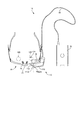
図1には、本発明の第1実施形態に従う画像処理装置を実現するために使用される画像表示装置10が平面図で示されている。この画像表示装置10は、シースルー型のHMD12を有する。このHMD12は、画像を表す画像光を観察者の眼に投影するように構成されている。このHMD12は、ヘッドマウント装置14により、観察者が眼鏡(図示しない)を装着している状態で、観察者の頭部に装着される。
FIG. 1 is a plan view showing an
ヘッドマウント装置14は、フレーム16と、アタッチメント装置18とを備えている。フレーム16は、観察者が装着している眼鏡(図示しない)のフレームであるか、専用のフレームであるかを問わず、観察者の両耳にかけられる状態で観察者の頭部に装着される。このフレーム16の一部に、アタッチメント装置18を介してHMD12が搭載される。
The
次に、図1および図2を参照することにより、HMD12およびそのHMD12を制御するための制御ユニット20であってコンピュータを主体として構成されているものを説明する。本実施形態おいては、共に独立した部品であるHMD12と制御ユニット20とが互いに組み合わされて画像表示装置10を構成しているが、制御ユニット20をHMD12内に組み込むことによって画像表示装置10を構成してもよい。
Next, referring to FIGS. 1 and 2, the
まず、HMD12の概略を説明する。図1には、このHMD12が平面図で示されている。このHMD12は、単眼式であり、画像を表す画像光を観察者の片眼に投影して前記画像を観察者に表示する。さらに、HMD12は、網膜走査型であり、レーザ等、光源からの、画像信号に応じた強度を有する光束をスキャナによって走査し、その走査された光束を観察者の網膜に投影することにより、観察者が画像を虚像として観察することを可能にする。さらに、HMD12は、シースルー型であり、表示画像を観察者が現実外界に重ねて観察することを可能にする。
First, the outline of the
なお付言するに、本実施形態においては、HMD12が単眼式、網膜走査型およびシースルー型であるが、両眼式に変更したり、光源からの面状の光を、LCD(液晶ディスプレイ)、有機EL(エレクトロ・ルミネッセンス)等、空間変調素子を用いて、各画素ごとに空間的に変調し、その変調された光を観察者の網膜に投影する型式に変更したり、表示画像の観察と並行して現実外界を観察することができないクローズド型に変更することが可能である。
In addition, in this embodiment, the
本発明は、HMD12がシースルー型であるかクローズド型であるかを問わず、そのHMD12を使用して実施することが可能である。しかし、そのHMD12は、観察者が、HMD12による表示画像(例えば、図3に示す支援画像)と一緒に観察者が現実外界を観察することを可能にするものであることが、HMD12を使用して本発明を実施するための必要条件である。
The present invention can be implemented using the
そのため、HMD12がクローズド型である場合には、HMD12を、観察者の前方に位置する現実外界であって、HMD12がシースルー型であったならば観察者が観察し得たであろうシースルー画像(例えば、昼間においてカメラ21により撮像された、例えば図5に示すシースルー画像や、夜間において赤外線カメラ(図示しない)により撮像された暗視野画像)と同じ画像を第2の表示画像として観察者に表示するように構成することが必要である。
Therefore, when the
本実施形態においては、カメラ21(例えば、CCD(Charge-Coupled Device)カメラ)が、観察者の前方に位置する現実外界を撮像するために、フレーム16に固定されている。それにより、カメラ21は、フレーム16を介して間接的に、観察者の頭部に装着されている。これにより、カメラ21は、観察者の頭部の動きに応じ、HMD12と一緒に動くことになる。ただし、カメラ21は、例えば、HMD12に直接的に装着してもよいことは言うまでもない。
In the present embodiment, a camera 21 (for example, a CCD (Charge-Coupled Device) camera) is fixed to the
次に、制御ユニット20を説明する。HMD12に制御ユニット20が、図1に示すように、ケーブル22を介して接続されている。ケーブル22は、制御信号を供給する制御ラインと、電力を供給するパワーラインと、光を伝送する光ファイバ82(後に詳述する)とを含んでいる。HMD12が観察者の頭部に装着されるのに対し、制御ユニット20は、観察者のうち、頭部以外の部分(例えば、腰)に装着される。
Next, the
制御ユニット20は、図2に機能ブロック図で概念的に表すように、プロセッサとしてのCPU(Central Processing Unit)26と、不揮発性メモリとしてのプログラムROM(Read Only Memory)27およびフラッシュROM28と、揮発性メモリとしてのRAM(Ramdom Access Memory)29とを備えている。
The
制御ユニット20は、さらに、画像表示装置10の電源を投入・切断するためにユーザによって操作される電源スイッチ30aと、画像表示装置10の電源がオン状態にあることを示すために点灯させられる電源ランプ30bと、操作部(図示しないが、例えば、複数のキーやボタン)とを備えている。
The
制御ユニット20は、さらに、ネットワーク・インタフェース(図2においては、「ネットワークI/F」で表す。)31aと、周辺インタフェース31b(図2においては、「周辺I/F」で表す。)と、ビデオRAM32aと、HMD接続インタフェース・コントローラ32b(図2においては、「HMD接続I/Fコントローラ」で表す。)と、バス33とを備えている。周辺インタフェース31bに、カメラ21と、電源スイッチ30aと、電源ランプ30bとが接続され、また、HMD接続インタフェース・コントローラ32bにHMD12が接続されている。
The
バス33を介して、CPU26、プログラムROM27、フラッシュROM28、RAM29、ネットワーク・インタフェース31a、周辺インタフェース31b、ビデオRAM32aおよびHMD接続インタフェース・コントローラ32bが相互に接続されている。さらに、ネットワーク・インタフェース31aおよびビデオRAM32aが相互に直接接続され、また、同様に、ビデオRAM32aおよびHMD接続インタフェース・コントローラ32bが相互に直接接続されている。
The
周辺インタフェース31bには、パーソナルコンピュータ等、外部機器(図示しない)が接続され、その外部機器から、周辺インタフェース31bを介して、映像信号が制御ユニット20に入力される。映像信号は、画像表示装置10によって再生されるべき表示コンテンツを表す。その入力された表示コンテンツを表すデータは、後述の支援画像を表す支援画像データを含んでおり、その支援画像データは、フラッシュROM28に保存される。
An external device (not shown) such as a personal computer is connected to the
網膜124に入射した画像光により、観察者が2次元画像を虚像として観察することが可能となる。観察者の片眼には、ハーフミラー112において反射した画像光のみならず、現実外界からの光(外光)がハーフミラー112を透過して入射する。その結果、観察者は、画像光によって表示される画像の観察と並行して現実外界を観察することが可能となる。
The image light incident on the
図3に示す例においては、HMD12が、画像信号に応じた画像を全体画像表示エリア(前記第1画像表示エリアの一例)126内に表示画像として表示する。この例においては、その表示画像が、第1画像表示エリア126内の所定位置に配置され、その第1画像表示エリア126より小さい第1サブエリア127内に表示される。その表示画像は、この例においては、前述のように、観察者である作業者による作業を支援するために作業者に表示される支援画像である。作業者は、その支援画像と共に、現実外界内の対象物128(図3に示す例においては、地面から垂直に真っ直ぐに延びる1本の樹木)をシースルー画像として観察する。作業者の頭部には、HMD12に加えて、カメラ21も装着されており、そのカメラ21は、前記表示画像と一緒に作業者が観察している対象物128を撮像する。
In the example shown in FIG. 3, the
本実施形態においては、カメラ21を使用する目的が、HMD12を装着しつつ対象物128を観察しながら作業を行っている作業者による作業を、遠隔地において、その作業者とは別の者である作業支援者が支援することを可能にすることにある。具体的には、カメラ21は、作業者が観察している対象物128を遠隔地において作業支援者がリアルタイムでモニタするために、対象物128を撮像する。
In the present embodiment, the purpose of using the
このような遠隔支援という目的を達するために、図2に示すように、作業者によって使用されるHMD12を有する画像表示装置10と、作業支援者によって使用されるモニタ装置130とが、無線または有線のネットワーク(例えば、LAN)140を介して相互に接続されている。図4(a)には、作業者が、自身の頭部にHMD12とカメラ21とが装着されている状態で対象物128を観察している様子と、遠隔地にいる作業支援者が、作業者が観察している対象物128であって、作業者の頭部に装着されたカメラ21によって撮像されたものをモニタ装置130においてモニタ画像としてリアルタイムで監視している様子とが概念的に示されている。この遠隔支援システムによれば、観察者の視界の状態および/または対象物の状態を遠隔地において、観察者とは別の者がモニタすることが可能となる。
In order to achieve the purpose of such remote support, as shown in FIG. 2, the
図2に示すように、モニタ装置130は、コンピュータを主体として構成されている。具体的には、モニタ装置130は、プロセッサとしてのCPU142と、不揮発性メモリとしてのROM144と、揮発性メモリとしてのRAM146と、それら要素を互いに接続するバス148とを備えている。
As shown in FIG. 2, the
そのバス148には、前記モニタ画像が表示される画像表示エリア(前記第2画像表示エリアの一例)を有する画面150(図4(a)参照)と、その画面150の表示動作を制御する表示コントローラ(図示しない)とを有する表示部160と、モニタ装置130にデータを入力するために作業支援者によって操作される操作部162とが接続され、さらに、ネットワーク・インタフェース(図2においては、「ネットワークI/F」で表す。)164も接続されている。このネットワーク・インタフェース164は、ネットワーク140に接続されており、このネットワーク140に、画像表示装置10内のネットワーク・インタフェース31aも接続されている。これにより、画像表示装置10とモニタ装置130とが相互に通信可能となっている。その結果、作業者と作業支援者との間に遠隔支援システムが構築される。
The
この遠隔支援システムにつき、本発明者が研究を行ったところ、特別の対策を講じない従来の遠隔支援システムには、次のような不都合があることが判明した。このことを、図4(b)を参照しつつ具体的に説明する。 As a result of research conducted by the inventor on the remote support system, it has been found that the conventional remote support system which does not take special measures has the following disadvantages. This will be specifically described with reference to FIG.
作業者が、自身の頭部にHMD12とカメラ21とが装着されている状態で、首を傾けると、HMD12およびカメラ21も一緒に傾き、その結果、カメラ21によって撮像されたカメラ画像内において対象物128の像も傾くことになる。
When the operator tilts his / her head with the
そのため、モニタ装置130を、カメラ画像をそのままモニタ画像として表示するように設計すると、対象物128自体は、図4(b)において中央位置に示すように、絶対空間に対して(重力方向に対して)、全く傾いていないにもかかわらず、モニタ装置130の画面150上に表示される対象物128の像が、図4(b)において右側に示すように、モニタ画像の枠に対して相対的に、作業者が首を傾けた向きとは逆の向きに、かつ、首の傾き角と同じ角度で傾くことになる。作業者が首を傾ける行為は、傾き角度の差はあるにしても、頻繁に起こるため、作業支援者は、現実には傾斜していない対象物128を、画面150上において、左右に繰り返し傾く状態で観察することになる。
Therefore, when the
ところで、特定の方向を表現するために、絶対空間上で方向を定義する用語を使用する場合がある。そのような用語としては、例えば、上、下、左、右、縦、横、垂直、水平などがある。そこで、対象物128が画面150上に傾斜状態で表示されている状態で、作業支援者が、対象物128である樹木について特定の方向を、絶対空間上で方向を定義する用語を用いて、指示する場合について検討する。
By the way, in order to express a specific direction, the term which defines a direction on absolute space may be used. Examples of such terms include up, down, left, right, portrait, landscape, vertical, and horizontal. Therefore, in a state where the
一例として、作業支援者が、絶対空間上で定義される方向を用いなければ、「樹木の先端部から、その樹木を延長する方向」とでも表現すべき方向を指示することが必要である場合を想定する。この場合、作業支援者は、樹木が傾斜して表示されているモニタ画像を見ながら、絶対空間上で定義される用語である「上方」という用語を使用して、例えば、「樹木の先端部から左斜め上方」と表現する可能性がある。 As an example, if the work supporter does not use the direction defined in the absolute space, it is necessary to indicate the direction to be expressed as "the direction in which the tree is extended from the tip of the tree" Is assumed. In this case, the work supporter uses the term “upward”, which is a term defined in absolute space, while looking at the monitor image in which the tree is displayed with an inclination, for example, “the tip of the tree” There is a possibility that it is expressed as “left diagonally upward”.
この場合、その表現を作業者が聞くと、作業者は、「現実外界において重力方向に延びる樹木の先端部から左斜め上方」を意味する表現であると解釈する可能性がある。この解釈は、上述の、「樹木の先端部から、その樹木を延長する方向」に一致しない。そのため、作業支援者の、方向に関する指示が、作業者によって正しく理解されないという不都合が発生する。 In this case, when the worker listens to the expression, the worker may interpret that the expression means “diagonally left upward from the tip of the tree extending in the direction of gravity in the real world”. This interpretation does not coincide with the above-mentioned “direction in which the tree extends from the tip of the tree”. For this reason, there arises a disadvantage that the instruction regarding the direction of the work supporter is not correctly understood by the worker.
このような、作業支援者と作業者との間の、方向に関する認識の不一致を防止するために、本実施形態においては、図4(c)に示すように、作業者の頭部の、重力方向に対する傾き角が検出され、その検出された傾き角に応じ、対象物128を撮像したカメラ画像の、重力方向に対する傾きを、前記傾き角の向きとは逆向きに、かつ、実質的に同じ角度で補正する画像傾き補正が行われる。ただし、この画像傾き補正は、HMD12による表示画像(前述の支援画像)に対しては行われない。
In order to prevent such a discrepancy in recognition of direction between the work supporter and the worker, in this embodiment, as shown in FIG. An inclination angle with respect to the direction is detected, and the inclination of the camera image obtained by imaging the
上述の画像傾き補正が実施されると、対象物128を撮像したカメラ画像に対して、モニタ装置130の画面150上に表示されるべきモニタ画像が生成され、その結果、作業者の頭部の傾斜の有無にかかわらず、対象物128が、絶対空間上における実際の向きと同じ向きを有するように、画面150上に表示される。図4に示す例においては、作業者の頭部の傾斜の有無にかかわらず、対象物128が常に、画面150上に重力方向に延びる姿勢で表示される。
When the above-described image inclination correction is performed, a monitor image to be displayed on the
その結果、作業者が認識している対象物128の向きと、作業支援者が画面130上において観察している対象物128の向き(絶対空間上における向き)とが常に互いに一致し、それにより、作業支援者と作業者との間の、方向に関する認識の不一致が防止される。
As a result, the orientation of the
さらに、上述の画像傾き補正が実施されると、実際の対象物128の向きが変化しない限り、作業者の頭部の傾斜の有無にかかわらず、対象物128が常に、画面150上に同じ方向に延びる姿勢で表示され、それにより、画面150上のモニタ画像における対象物128の向きが安定する。
Further, when the above-described image tilt correction is performed, the
以上、概略的に説明した画像傾き補正を実施するために、本実施形態においては、図2に示すように、HMD12が装着されている作業者の頭部に傾き角センサ170が装着され、さらに、前記画像傾き補正を行うためのいくつかのプログラムが画像表示装置10のプログラムROM27と、モニタ装置130のROM144とに予め記憶されている。傾き角センサ170は、周辺インタフェース31bに電気的に接続されている。
As described above, in order to perform the image tilt correction schematically described above, in the present embodiment, as shown in FIG. 2, the
傾き角センサ170は、作業者の頭部の傾きの向き(右方向か左方向か)と角度とを検出するために作業者の頭部に装着される。傾き角センサ170は、作業者の頭部に直接的に装着されてもよいが、頭部に直接的に装着される別の部材、例えば、HMD12、フレーム16、カメラ21などに直接的に装着してもよい。この傾き角センサ170は、作業者の頭部の、前後方向に延びる軸線まわりの回転を検出する。この傾き角センサ170は、例えば、ジャイロセンサを主体とするものとすることが可能である。この場合、ジャイロセンサによって検出された角速度を時間積分することにより、頭部の傾き角を計算することが可能である。
The
次に、前記画像傾き補正のための画像処理を詳細に説明する。 Next, image processing for correcting the image tilt will be described in detail.
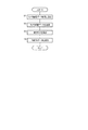
図5には、画像表示装置10のCPU26によって実行されるデータ送信プログラムが概念的にフローチャートで表されている。このデータ送信プログラムは、画像表示装置10の電源がオンである間、繰り返し実行される。各回の実行時には、まず、ステップS1において、カメラ21から、それの撮像結果を表すカメラ画像データ(補正前カメラ画像データ)がCPU26に取り込まれる。次に、ステップS2において、その取り込まれたカメラ画像データが、ネットワーク・インタフェース31aから、ネットワーク140を介して、モニタ装置130に送信される。
FIG. 5 conceptually shows a data transmission program executed by the
続いて、ステップS3において、傾き角センサ170からのセンサ信号がCPU26に取り込まれ、そのセンサ信号に基づき、作業者の頭部の傾き角θが検出される。その後、ステップS4において、その検出された傾き角θを表す傾き角データが、ネットワーク・インタフェース31aから、ネットワーク140を介して、モニタ装置130に送信される。以上で、このデータ送信プログラムの一回の実行が終了する。
Subsequently, in step S3, the sensor signal from the
図6には、モニタ装置130のCPU142によって実行される基準傾き角設定プログラムが概念的にフローチャートで表されている。この基準傾き角設定プログラムは、モニタ装置130の電源がオンである間、繰り返し実行される。
In FIG. 6, a reference inclination angle setting program executed by the
作業支援者は、各回の遠隔支援作業に先立ち、作業者の頭部傾き角検出値のためのキャリブレーション作業を行う。具体的には、作業支援者は、画像表示装置10から受信したカメラ画像データに基づいて画面150上に現在表示されている現実外界の向き(例えば、対象物128の向き)から、作業者の頭部に装着されているカメラ21が水平面上に位置するか否か(例えば、カメラ画像における対象物128が画面150上において垂直に延びているか否か)を判断する。作業支援者は、カメラ21が水平面上に位置すると判断すると、操作部162を介して、水平リセット操作を行う。
The work supporter performs a calibration work for the head inclination angle detection value of the worker prior to each remote support work. Specifically, the work supporter can determine the worker's direction from the direction of the actual outside world currently displayed on the screen 150 (for example, the direction of the object 128) based on the camera image data received from the
なお付言するに、同様なキャリブレーション作業は、作業支援者に代えて、カメラ21が装着されている作業者が自ら行うことも可能である。例えば、画像表示装置10において、前記ジャイロセンサによって検出された角速度を、基準時刻、すなわち、作業者の頭部が正立位置にあることが作業者によって入力された時刻から時間積分することにより、頭部の傾き角を、重力方向に対する相対角(絶対空間上における絶対角に等しい)として計算することが可能である。
It should be noted that the same calibration work can be performed by the worker wearing the
しかし、作業者は、カメラ21が作業者の頭部に傾いて装着されていても、そのことに気付くことができない可能性がある。この場合には、作業者は、上述のキャリブレーション作業を精度よく行うことができない。
However, even if the
これに対し、作業支援者は、作業者の頭部の傾きのみならず、カメラ21の、作業者に対する装着のずれ角をも反映するカメラ画像を用いて、作業者が観察している現実外界の向きを画面150上において確認できる。よって、作業支援者は、上述のキャリブレーション作業を精度よく行うことができる。
In contrast, the work supporter uses the camera image that reflects not only the inclination of the head of the worker but also the mounting angle of the
図6に示す基準傾き角設定プログラムは各回の実行時には、まず、ステップS101において、作業支援者が、操作部162に対し、前記水平リセット操作を行ったか否かが判定される。今回は、作業支援者が水平リセット操作を行っていないと仮定すると、直ちに、この基準傾き角設定プログラムの一回の実行が終了する。
When the reference inclination angle setting program shown in FIG. 6 is executed each time, first, in step S101, it is determined whether or not the work support person has performed the horizontal reset operation on the
これに対し、今回は、作業支援者が水平リセット操作を行ったと仮定すると、ステップS102において、画像表示装置10から最新の前記傾き角データを受信する。続いて、ステップS103において、その受信された傾き角データによって表される傾き角θが、基準傾き角θREFに設定される。その設定された基準傾き角θREFは、後の使用に備えて、RAM146に保存される。傾き角θと設定傾き角θREFとの差が、作業者の頭部の、絶対空間上における、重力方向からの傾き角(以下、「絶対傾き角θabs」という。)を表す。以上で、この基準傾き角設定プログラムの一回の実行が終了する。
On the other hand, this time, assuming that the work supporter has performed a horizontal reset operation, the latest tilt angle data is received from the
図7には、モニタ装置130のCPU142によって実行される画像表示プログラムが概念的にフローチャートで表されている。この画像表示プログラムは、モニタ装置130の電源がオンである間、繰り返し実行される。
FIG. 7 conceptually shows a flowchart of an image display program executed by the
各回の実行時には、まず、ステップS201において、画像表示装置10から、最新のカメラ画像データと、最新の傾き角データとが受信される。次に、ステップS202において、その受信された傾き角データにより表される現在の傾き角θが、前記基準傾き角θREFからずれているか否か、すなわち、前記絶対傾き角θabsが0であるか否かがが判定される。これにより、作業者の頭部が、重力方向に対して傾斜しているか否かが判定され、その結果、カメラ画像における対象物128が、そのカメラ画像の枠に対して傾斜しているか否かが判定される。
At the time of each execution, first, in step S201, the latest camera image data and the latest tilt angle data are received from the
今回は、現在の傾き角θが基準傾き角θREFからずれていないと仮定すると、ステップS203において、前記画像傾き補正が行われることなく、画面150上に表示されるべきモニタ画像を表すモニタ画像データが、カラー画像データと同じ画像を表すデータとなるように生成される。
This time, assuming that the current inclination angle θ is not deviated from the reference inclination angle θREF, monitor image data representing a monitor image to be displayed on the
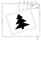
これに対し、今回は、現在の傾き角θが基準傾き角θREFからずれていると仮定すると、ステップS204において、カラー画像データに対して前記画像傾き補正が行われる。具体的には、図8(a)に示すように、まず、画像傾き補正前のカメラ画像である元カメラ画像を、指定された回転中心点(例えば、元カメラ画像の中心点と一致する位置)まわりに、絶対傾き角θabsとは逆向きに、かつ、絶対傾き角θabsと実質的に同じ角度で回転させる画像回転処理が行われる。図8(a)には、画像回転処理後の元カメラ画像が示されている。この段階で、その画像内の対象物128は、作業者の頭部の絶対傾き角θabsが0ではないにもかかわらず、重力方向に延びている。
In contrast, assuming that the current inclination angle θ is deviated from the reference inclination angle θREF this time, the image inclination correction is performed on the color image data in step S204. Specifically, as shown in FIG. 8A, first, an original camera image that is a camera image before image tilt correction is set to a position that matches a specified rotation center point (for example, the center point of the original camera image). ) Around the image is rotated in the direction opposite to the absolute inclination angle θabs and substantially the same as the absolute inclination angle θabs. FIG. 8A shows the original camera image after the image rotation process. At this stage, the
次に、その画像回転処理後の元カメラ画像から、形状とサイズとが指定された部分画像を切り取るトリミング処理が行われる。その部分画像は、それの中心点が、元カメラ画像の中心点と一致するように、元カメラ画像に対して位置決めされる。このトリミング処理により、画面150上に全体的に表示されるべきモニタ画像が生成される。画面150と、その画面150上に表示されるべきモニタ画像(矩形の画像)とは、サイズも形状も、互いに一致する。
Next, a trimming process is performed to cut out a partial image having a specified shape and size from the original camera image after the image rotation process. The partial image is positioned with respect to the original camera image such that its center point coincides with the center point of the original camera image. By this trimming process, a monitor image to be displayed on the
その後、ステップS205において、その生成されたモニタ画像を表すモニタ画像データが生成される。 Thereafter, in step S205, monitor image data representing the generated monitor image is generated.
ステップS203の実行時であるかステップS205の実行時であるかを問わず、その後、ステップS206において、生成されたモニタ画像データに基づき、モニタ画像が画面150上に表示される。
Regardless of whether step S203 is executed or step S205 is executed, a monitor image is then displayed on the
続いて、ステップS207において、画像表示装置10から送信された信号が、前記モニタ画像と同じ画像をHMD12でも表示するためのリクエスト(後述のチェック画像表示リクエスト)を作業者が画像表示装置10に対して入力したことを表しているか否かが判定される。そのチェック画像表示リクエストを作業者が入力していない場合には、直ちに、この画像表示プログラムの一回の実行が終了するが、そのチェック画像表示リクエストを作業者が入力した場合には、ステップS208において、前記モニタ画像データが、チェック画像をHMD12において表示するために、画像表示装置10に送信される。以上で、この画像表示プログラムの一回の実行が終了する。
Subsequently, in step S207, the operator sends a request (a check image display request described later) for displaying the same image as the monitor image on the
ここで、図8を参照することにより、画像傾き補正のアルゴリズムについてのいくつかの例を説明する。図8(a)に示すアルゴリズムの例においては、前述のように、モニタ画像の中心点がカメラ画像の中心点に一致する状態で、カメラ画像が回転させられ、その回転角がそれほど大きくないことと、モニタ画像のサイズがそれほど大きくないこととが相俟って、モニタ画像が、回転後のカメラ画像からはみ出さずに済む。 Here, with reference to FIG. 8, some examples of the image tilt correction algorithm will be described. In the example of the algorithm shown in FIG. 8A, as described above, the camera image is rotated in a state where the center point of the monitor image coincides with the center point of the camera image, and the rotation angle is not so large. In combination with the fact that the size of the monitor image is not so large, the monitor image does not protrude from the rotated camera image.
これに対し、図8(b)に示すアルゴリズムの例においては、作業支援者の操作により、モニタ画像の中心点が、カメラ画像の中心点から移動させられ、その結果、モニタ画像の一部が元カメラ画像からはみ出している。モニタ画像のうち、元カメラ画像からはみ出している部分は、カメラ画像データが存在しない部分であり、この部分は、特に対策を講じないと、画面150上に表示することができない。
On the other hand, in the example of the algorithm shown in FIG. 8B, the center point of the monitor image is moved from the center point of the camera image by the operation of the work supporter, so that a part of the monitor image is obtained. It protrudes from the original camera image. The portion of the monitor image that protrudes from the original camera image is a portion where no camera image data exists, and this portion cannot be displayed on the
そこで、このアルゴリズムの例においては、モニタ画像のうち、元カメラ画像からはみ出している部分が、黒色に着色されるように、モニタ画像データが生成される。これにより、作業支援者は、モニタ画像中に、カメラ21の視野からはみ出した部分が存在することを知ることができる。
Therefore, in this algorithm example, monitor image data is generated so that the portion of the monitor image that protrudes from the original camera image is colored black. Thereby, the work supporter can know that the monitor image includes a portion that protrudes from the field of view of the
図8(a)に示すアルゴリズムの例においては、カメラ画像がモニタ画像に対して回転させられる角度が小さいため、モニタ画像が、回転後のカメラ画像からはみ出さずに済むが、その角度が大きい場合には、モニタ画像が回転後のカメラ画像からはみ出してしまう。これに対し、図8(c)に示すアルゴリズムの例においては、モニタ画像が回転後のカメラ画像からはみ出すことがない最大面積を有するように、カメラ画像の回転角に応じて、モニタ画像のサイズが伸縮させられる。 In the example of the algorithm shown in FIG. 8A, since the angle at which the camera image is rotated with respect to the monitor image is small, the monitor image does not protrude from the rotated camera image, but the angle is large. In such a case, the monitor image protrudes from the rotated camera image. On the other hand, in the example of the algorithm shown in FIG. 8C, the size of the monitor image is set according to the rotation angle of the camera image so that the monitor image has a maximum area that does not protrude from the rotated camera image. Can be stretched.
図9には、画像表示装置10のCPU26によって実行される画像表示プログラムが概念的にフローチャートで表されている。この画像表示プログラムは、画像表示装置10の電源がオンである間、繰り返し実行される。各回の実行時には、まず、ステップS301において、フラッシュROM27から、第1サブエリア127内に表示すべき支援画像(図10参照)を表す支援画像データが読み込まれる。
FIG. 9 conceptually shows a flowchart of an image display program executed by the
次に、ステップS302において、作業者が、画像表示装置10に対し、前記支援画像と共に、前記チェック画像(図10参照)を第2サブエリア180内に表示するためのチェック画像表示リクエストを入力したか否かが判定される。第2サブエリア180は、全体画像表示エリア126内の所定位置であって、第1サブエリア127から視覚的に区別され、かつ、それとはオーバラップしない位置に配置されている。
Next, in step S302, the operator inputs a check image display request for displaying the check image (see FIG. 10) in the
作業者が前記チェック画像表示リクエストを入力していない場合には、ステップS303において、前記読み込まれた支援画像データをそのまま用いて、表示画像データが生成される。 If the operator has not input the check image display request, display image data is generated in step S303 using the read support image data as it is.
これに対し、作業者が前記チェック画像表示リクエストを入力した場合には、ステップS304において、モニタ装置130から前記モニタ画像データが受信される。続いて、ステップS305において、その受信されたモニタ画像データに基づき、作業支援者が現在観察しているモニタ画像を同じものを縮小状態で、第2サブエリア180内に前記チェック画像としてリアルタイムで表示するためのデータがチェック画像データとして生成される。
On the other hand, when the operator inputs the check image display request, the monitor image data is received from the
その後、ステップS306において、前記読み込まれた支援画像データと、前記生成されたチェック画像データとを合成することにより、表示画像データが生成される。その生成された表示画像データは、図10に示すように、支援画像を第1サブエリア126内に表示することと、チェック画像を第2サブエリア180内に表示することとを一緒に行うためのデータである。
Thereafter, in step S306, display image data is generated by synthesizing the read support image data and the generated check image data. As shown in FIG. 10, the generated display image data is used to display the support image in the
ステップS303の実行時であるかステップS306の実行時であるかを問わず、その後、ステップS307において、前記生成された表示画像データに基づき、HMD12において画像を表示するための表示信号(例えば、HMD12が前述の網膜走査型である場合には、レーザ等、光源を制御するための信号(例えば、輝度信号、強度信号)であり、また、HMD12が前述の空間変調型である場合には、LCD、有機EL等、空間変調素子を制御するための信号(例えば、画素信号)である)が生成される。続いて、ステップS308において、その生成された表示信号が、前記光源または前記空間変調素子に出力される。それにより、図10に示すように、支援画像が第1サブエリア126内に表示され、また、作業者が前記チェック画像表示リクエストを入力した場合には、併せて、チェック画像が第2サブエリア180内に表示される。以上で、この画像表示プログラムの一回の実行が終了する。
Regardless of whether step S303 is executed or step S306 is executed, after that, in step S307, based on the generated display image data, a display signal (for example, HMD12) for displaying an image on the
これにより、作業者は、現実外界内の対象物128をシースルー画像として観察しつつ、支援画像を観察し、さらに、チェック画像を観察することが可能となる。そのチェック画像の観察により、作業者は、作業支援者が観察しているモニタ画像(例えば、作業支援者が特定の方向を作業者に指示する際に、その指示の根拠となった画像)と同じ画像を、縮小状態で、リアルタイムで確認することが可能となる。
Thus, the operator can observe the support image and the check image while observing the
次に、本発明の第2実施形態を説明する。ただし、本実施形態は、第1実施形態と共通する要素が多いため、異なる要素についてのみ詳細に説明し、共通の要素については、同一の符号または名称を使用して引用することにより、重複した説明を省略する。 Next, a second embodiment of the present invention will be described. However, since this embodiment has many elements in common with the first embodiment, only different elements will be described in detail, and the common elements will be duplicated by quoting using the same symbols or names. Description is omitted.
第1実施形態においては、前記画像傾き補正という画像処理がモニタ装置130において実行されるようになっていた。これに対し、本実施形態においては、同じ画像処理が画像表示装置10において行われる。
In the first embodiment, the image processing called the image inclination correction is executed in the
本実施形態においては、画像表示装置10のCPU26により、図11に概念的にフローチャートで表されている画像表示プログラムが、図5に示すデータ送信プログラムおよび図9に示す画像表示プログラムに代えて実行される。さらに、図6に示す基準傾き角設定プログラムがモニタ装置130のCPU142により実行される代わりに、図6に示す基準傾き角設定プログラムと実質的に同じプログラムが、画像表示装置10のCPU26により実行される。
In the present embodiment, the
図11に示す画像表示プログラムの各回の実行時には、まず、ステップS401において、図9に示すステップS301と同様にして、前記支援画像データがフラッシュROM28から読み込まれ、次に、ステップS402において、図5に示すステップS3と同様にして、前記傾き角θが検出される。続いて、ステップS403において、図5に示すステップS1と同様にして、カメラ画像データがカメラ21から取り込まれる。
When the image display program shown in FIG. 11 is executed each time, first, in step S401, the support image data is read from the
その後、ステップS404ないしS407が、図7に示すステップS202ないしS205と同様にして実行される。続いて、ステップS408において、ステップS405またはS407の実行によって形成されたモニタ画像データがモニタ装置130に送信される。
Thereafter, steps S404 to S407 are executed in the same manner as steps S202 to S205 shown in FIG. Subsequently, in step S <b> 408, monitor image data formed by executing step S <b> 405 or S <b> 407 is transmitted to the
続いて、ステップS409において、図9に示すステップS302と同様にして、作業者が、画像表示装置10に対し、前記チェック画像表示リクエストを入力したか否かが判定される。作業者が前記チェック画像表示リクエストを入力していない場合には、ステップS410において、図9に示すステップS303と同様にして、前記読み込まれた支援画像データをそのまま用いて、表示画像データが生成される。
Subsequently, in step S409, similarly to step S302 shown in FIG. 9, it is determined whether or not the operator has input the check image display request to the
これに対し、作業者が前記チェック画像表示リクエストを入力した場合には、ステップS411において、図9に示すステップS305に準じて、ステップS403において取り込まれたモニタ画像データに基づき、前記チェック画像データとして生成される。その後、ステップS412において、図9に示すステップS306と同様に、ステップS401において読み込まれた支援画像データと、ステップS411において生成されたチェック画像データとを合成することにより、前記表示画像データが生成される。 On the other hand, when the operator inputs the check image display request, in step S411, as the check image data, based on the monitor image data captured in step S403 in accordance with step S305 shown in FIG. Generated. Thereafter, in step S412, the display image data is generated by synthesizing the support image data read in step S401 and the check image data generated in step S411 similarly to step S306 shown in FIG. The
ステップS410の実行時であるかステップS412の実行時であるかを問わず、その後、ステップS413において、図9に示すステップS307と同様にして、前記生成された表示画像データに基づき、前記表示信号が生成される。続いて、ステップS414において、図9に示すステップS308と同様にして、前記生成された表示信号が前記光源または前記空間変調素子に出力されることにより、支援画像が第1サブエリア126内に表示され、また、作業者が前記チェック画像表示リクエストを入力した場合には、併せて、チェック画像が第2サブエリア180内に表示される。以上で、この画像表示プログラムの一回の実行が終了する。
Regardless of whether step S410 is executed or step S412 is executed, in step S413, the display signal is generated based on the generated display image data in the same manner as step S307 shown in FIG. Is generated. Subsequently, in step S414, as in step S308 shown in FIG. 9, the generated display signal is output to the light source or the spatial modulation element, so that a support image is displayed in the
さらに、本実施形態においては、モニタ装置130のCPU142により、図12に概念的にフローチャートで表されている画像表示プログラムが、図7に示す画像表示プログラムに代えて実行される。
Further, in the present embodiment, the
図11に示す画像表示プログラムの各回の実行時には、まず、ステップS501において、画像表示装置10から、前記モニタ画像データが受信される。次に、ステップS502において、その受信されたモニタ画像データに基づき、前記モニタ画像が画面150上に表示される。以上で、この画像表示プログラムの一回の実行が終了する。
When the image display program shown in FIG. 11 is executed each time, first, the monitor image data is received from the
次に、本発明の第3実施形態を説明する。ただし、本実施形態は、第2実施形態と共通する要素が多いため、異なる要素についてのみ詳細に説明し、共通の要素については、同一の符号または名称を使用して引用することにより、重複した説明を省略する。 Next, a third embodiment of the present invention will be described. However, since this embodiment has many elements in common with the second embodiment, only different elements will be described in detail, and the common elements will be duplicated by quoting using the same reference numerals or names. Description is omitted.
第2実施形態においては、作業支援者がモニタ装置130において観察しているモニタ画像と同じものがチェック画像としてHMD12によって表示され、それにより、作業者が、作業支援者が観察しているモニタ画像を確認することが可能であった。
In the second embodiment, the same monitor image that the work supporter is observing on the
これに対し、本実施形態においては、図14に示すように、画像表示装置10が、作業者が全体画像表示エリア126内において観察する全体画像(前記支援画像(虚像)と前記シースルー画像(実像)とを含む。)のうち、作業支援者がモニタ装置130において観察しているモニタ画像(対象物128の像とそれの背景画像とを含む矩形の画像)と一致する一致部分画像190を一致しない不一致部分画像192から視覚的に区別するための枠画像200(一致部分画像190を包囲する矩形の枠を表す画像)を全体画像表示エリア126内に表示するように設計されている。
On the other hand, in the present embodiment, as shown in FIG. 14, the
本実施形態においては、画像表示装置10のCPU26により、図13に概念的にフローチャートで表されている画像表示プログラムが、図11に示す画像表示プログラムに代えて実行される。
In the present embodiment, the
図13に示す画像表示プログラムの各回の実行時には、ステップS501ないしS508が、図11に示すS401ないしS408と同様にして実行される。 At each execution of the image display program shown in FIG. 13, steps S501 to S508 are executed in the same manner as S401 to S408 shown in FIG.
その後、ステップS509において、作業者が、画像表示装置10に対し、枠画像200を全体画像表示エリア126内に表示するための枠画像表示リクエストを入力したか否かが判定される。作業者が前記枠画像表示リクエストを入力していない場合には、ステップS410において、前記読み込まれた支援画像データをそのまま用いて、表示画像データが生成される。
Thereafter, in step S509, it is determined whether or not the operator has input a frame image display request for displaying the
これに対し、作業者が前記枠画像表示リクエストを入力した場合には、ステップS411において、前記生成されたモニタ画像データに基づき、枠画像200を表す枠画像データが生成される。
On the other hand, when the worker inputs the frame image display request, in step S411, frame image data representing the
このステップS411の詳細を説明するに、画像表示装置10においては、全体画像表示エリア126の中心位置と、カメラ画像の中心位置とが、例えば互いに一致するというように、両者の中心位置間の相対位置が既知である。さらに、全体画像表示エリア126とカメラ画像との間の相対回転角が0であるというように、両者間の相対角も既知である。さらに、全体画像表示エリア126とカメラ画像とが互いに一致するというように、両者間の、サイズおよび形状に関する関係も既知である。
The details of step S411 will be described. In the
すなわち、画像表示装置10においては、全体画像表示エリア126(前記全体画像)とカメラ画像との間の、相対位置、相対角、サイズおよび形状に関する関係が既知であり、よって、全体画像表示エリア126の幾何学的情報から、カメラ画像の幾何学的情報を一義的に誘導することが可能である。
That is, in the
さらに、画像表示装置10においては、ステップS506の実行の結果、モニタ画像とカメラ画像との間の、相対位置、相対角、サイズおよび形状に関する関係が既知である。したがって、画像表示装置10においては、全体画像表示エリア126の幾何学的情報から、モニタ画像の幾何学的情報(モニタ画像の枠に関する幾何学的情報を含む)を一義的に誘導することが可能である。
Further, in the
そこで、このステップS411においては、前記生成されたモニタ画像データに基づき、全体画像表示エリア126内の全体画像のうち、モニタ画像と一致する一致部分画像190が特定され、さらに、その一致部分画像190の枠を表す枠画像200の幾何学的情報が特定される。枠画像200の太さおよび線種は既知である。そして、枠画像200を表す枠画像データが生成される。
Therefore, in this step S411, a matching
その後、ステップS512において、前記読み込まれた支援画像データと、前記生成された枠画像データとを合成することにより、表示画像データが生成される。その生成された表示画像データは、図14に示すように、支援画像を第1サブエリア126内に表示することと、枠画像200を全体画像表示エリア126内に表示することとを一緒に行うためのデータである。
After that, in step S512, display image data is generated by synthesizing the read support image data and the generated frame image data. As shown in FIG. 14, the generated display image data displays the support image in the
ステップS510の実行時であるかステップS512の実行時であるかを問わず、その後、ステップS513において、前記生成された表示画像データに基づき、前記表示信号が生成される。続いて、ステップS514において、その生成された表示信号が、前記光源または前記空間変調素子に出力される。それにより、図14に示すように、支援画像が第1サブエリア126内に表示され、また、作業者が前記枠画像表示リクエストを入力した場合には、併せて、枠画像200が全体画像表示エリア126内に表示される。以上で、この画像表示プログラムの一回の実行が終了する。
Regardless of whether step S510 is executed or step S512 is executed, the display signal is then generated in step S513 based on the generated display image data. Subsequently, in step S514, the generated display signal is output to the light source or the spatial modulation element. As a result, as shown in FIG. 14, when the support image is displayed in the
これにより、作業者は、現実外界内の対象物128をシースルー画像として観察しつつ、支援画像を観察し、さらに、作業支援者がモニタ装置130において観察しているモニタ画像と同じもの(モニタ画像における対象物128と同じ向き)を、枠画像200の向きを考慮して、リアルタイムで観察することが可能となる。これにより、作業者は、作業支援者が観察しているモニタ画像における対象物128の、そのモニタ画像の枠に対する相対的な向きを、作業支援者と共通に認識することができる。
Thus, the operator observes the support image while observing the
以上の説明から明らかなように、本実施形態においては、説明の便宜上、傾き角センサ170と、画像表示装置10のうち、図5に示すステップS3を実行する部分とが互いに共同して、前記(1)項における「傾き角検出部」の一例を構成し、また、画像表示装置10のうち、図5に示すステップS1、S2およびS4を実行する部分と、モニタ装置130のうち、図6に示す基準傾き角設定プログラムを実行する部分と、画像表示装置10のうち、図9に示すステップS302ないしS306を実行する部分とが互いに共同して、同項における「画像傾き補正部」の一例を構成していると考えることが可能である。
As is clear from the above description, in the present embodiment, for convenience of explanation, the
さらに、本実施形態においては、説明の便宜上、ネットワークI/F31aと、画像表示装置10のうち、図5に示すステップS1、S2およびS4を実行する部分とが互いに共同して、前記(2)項における「送信部」の一例を構成し、また、モニタ装置130のうち、図7に示すステップS201、S202、S204およびS205を実行する部分が、同項における「画像傾き補正部」の一例を構成していると考えることが可能である。
Furthermore, in the present embodiment, for convenience of explanation, the network I /
さらに、本実施形態においては、説明の便宜上、画像表示装置10のうち、図11に示すステップS402ないしS404、S406およびS407を実行する部分が、前記(3)項における「画像傾き補正部」の一例を構成し、また、ネットワークI/F31aと、画像表示装置10のうち、図11に示すステップS408を実行する部分とが互いに共同して、同項における「送信部」の一例を構成していると考えることが可能である。
Further, in the present embodiment, for convenience of explanation, the portion of the
さらに、本実施形態においては、説明の便宜上、画像表示装置10のうち、図9に示すステップS302およびS304ないしS306を実行する部分が、前記(4)項における「チェック画像表示部」の一例を構成し、また、画像表示装置10のうち、図13に示すステップS502ないしS504、S506、S507およびS509ないしS512を実行する部分が、前記(5)項における「枠画像表示部」の一例を構成していると考えることが可能である。
Furthermore, in the present embodiment, for the sake of convenience of explanation, the part that executes steps S302 and S304 to S306 shown in FIG. 9 in the
以上、本発明のいくつかの実施形態を図面に基づいて詳細に説明したが、これらは例示であり、前記[発明の概要]の欄に記載の態様を始めとして、当業者の知識に基づいて種々の変形、改良を施した他の形態で本発明を実施することが可能である。 As mentioned above, although several embodiment of this invention was described in detail based on drawing, these are illustrations and are based on the knowledge of those skilled in the art including the aspect as described in the above-mentioned [summary of invention] column. The present invention can be implemented in other forms with various modifications and improvements.
Claims (6)
当該画像処理装置は、前記HMDを有する画像表示装置とモニタ装置とのうちの少なくとも前記画像表示装置に設けられ、
前記HMDは、画像信号に応じた画像を表す画像光を観察者の眼に投影し、それにより、前記画像を第1画像表示エリア内に表示画像として表示し、
前記モニタ装置は、前記画像表示装置から無線または有線で受信した、前記カメラ画像を表すカメラ画像データに基づき、前記カメラ画像をモニタ画像として第2画像表示エリア内に表示し、
当該画像処理装置は、
観察者の頭部の、重力方向に対する傾き角を検出し、その検出された傾き角を表す傾き角データを出力する傾き角検出部と、
その出力された傾き角データに基づき、画像の、重力方向に対する傾きを、前記検出された傾き角の向きとは逆向きに、かつ、実質的に同じ角度で補正する画像傾き補正を、前記カメラ画像データに対しては行うが、前記表示画像を表す表示画像データに対しては行わない画像傾き補正部と
を含み、
前記モニタ装置は、前記画像傾き補正が行われたカメラ画像データである補正後カメラ画像データに基づき、前記モニタ画像を前記第2画像表示エリア内に表示する画像処理装置。 A camera image captured by a camera mounted on an observer's head together with a head-mounted display (HMD), and an object in the real outside world that the observer observes together with the display image by the HMD An image processing apparatus that performs image processing on a captured image,
The image processing device is provided in at least the image display device of the image display device and the monitor device having the HMD,
The HMD projects image light representing an image according to an image signal onto an observer's eye, thereby displaying the image as a display image in a first image display area,
The monitor device displays the camera image as a monitor image in a second image display area based on camera image data representing the camera image received wirelessly or by wire from the image display device;
The image processing apparatus
An inclination angle detector that detects an inclination angle of the head of the observer with respect to the direction of gravity and outputs inclination angle data representing the detected inclination angle;
Based on the output tilt angle data, image tilt correction for correcting the tilt of the image with respect to the gravitational direction in a direction opposite to the direction of the detected tilt angle and substantially the same angle is performed. An image tilt correction unit that performs image data but does not perform display image data representing the display image,
The monitor device displays the monitor image in the second image display area based on corrected camera image data which is camera image data on which the image tilt correction has been performed.
前記画像表示装置に設けられ、前記カメラ画像データおよび前記傾き角データを前記モニタ装置に送信する送信部を含み、
前記画像傾き補正部は、前記モニタ装置に設けられ、前記送信部から受信した傾き角データに基づき、前記送信部から受信したカメラ画像データに対して前記画像傾き補正を行う請求項1に記載の画像処理装置。 further,
A transmission unit provided in the image display device, for transmitting the camera image data and the tilt angle data to the monitor device;
The said image inclination correction | amendment part is provided in the said monitor apparatus, Based on the inclination angle data received from the said transmission part, the said image inclination correction | amendment is performed with respect to the camera image data received from the said transmission part. Image processing device.
当該画像処理装置は、さらに、
前記画像表示装置に設けられ、前記補正後カメラ画像データを前記モニタ装置に送信する送信部を含み、
前記モニタ装置は、その送信部から受信した補正後カメラ画像データに基づき、前記モニタ画像を前記第2画像表示エリア内に表示する請求項1に記載の画像処理装置。 The image tilt correction unit is provided in the image display device, performs the image tilt correction on the camera image data based on the tilt angle data,
The image processing apparatus further includes:
A transmission unit that is provided in the image display device and transmits the corrected camera image data to the monitor device;
The image processing device according to claim 1, wherein the monitor device displays the monitor image in the second image display area based on the corrected camera image data received from the transmission unit.
前記画像表示装置に設けられ、前記補正後カメラ画像を前記第1画像表示エリア内の所定位置に配置されたサブエリア内に、観察者のためのチェック画像として表示するチェック画像表示部を含む請求項1ないし3のいずれかに記載の画像処理装置。 further,
And a check image display unit that is provided in the image display device and displays the corrected camera image as a check image for an observer in a sub-area arranged at a predetermined position in the first image display area. Item 4. The image processing device according to any one of Items 1 to 3.
前記画像表示装置に設けられ、前記対象物を表す外光を、前記表示画像を表す表示光と一緒に前記第1画像表示エリアに投影するシースルー形式であるか、前記カメラによって前記対象物を撮像し、その撮像された画像と前記表示画像との双方を表す表示光を前記第1画像表示エリアに投影する形式であるかを問わず、観察者が前記第1画像表示エリア内において観察する全体画像であって前記表示画像と前記対象物の像とを含むもののうち、前記補正後カメラ画像と一致する一致部分画像を一致しない不一致部分画像から視覚的に区別するための枠画像を前記第1画像表示エリア内に表示する枠画像表示部を含む請求項1ないし3のいずれかに記載の画像処理装置。 further,
The image display device is a see-through type in which external light representing the object is projected onto the first image display area together with display light representing the display image, or the object is imaged by the camera. Regardless of whether the display light representing both the captured image and the display image is projected onto the first image display area, the observer observes the entire image in the first image display area. Among the images including the display image and the image of the object, a frame image for visually distinguishing a matched partial image that matches the corrected camera image from a mismatched partial image is the first image. The image processing apparatus according to claim 1, further comprising a frame image display unit that displays in the image display area.
Priority Applications (2)
| Application Number | Priority Date | Filing Date | Title |
|---|---|---|---|
| JP2011019066A JP2012160898A (en) | 2011-01-31 | 2011-01-31 | Image processing apparatus |
| PCT/JP2012/051994 WO2012105499A1 (en) | 2011-01-31 | 2012-01-30 | Image processing device |
Applications Claiming Priority (1)
| Application Number | Priority Date | Filing Date | Title |
|---|---|---|---|
| JP2011019066A JP2012160898A (en) | 2011-01-31 | 2011-01-31 | Image processing apparatus |
Publications (1)
| Publication Number | Publication Date |
|---|---|
| JP2012160898A true JP2012160898A (en) | 2012-08-23 |
Family
ID=46602713
Family Applications (1)
| Application Number | Title | Priority Date | Filing Date |
|---|---|---|---|
| JP2011019066A Pending JP2012160898A (en) | 2011-01-31 | 2011-01-31 | Image processing apparatus |
Country Status (2)
| Country | Link |
|---|---|
| JP (1) | JP2012160898A (en) |
| WO (1) | WO2012105499A1 (en) |
Cited By (16)
| Publication number | Priority date | Publication date | Assignee | Title |
|---|---|---|---|---|
| JP2014068335A (en) * | 2012-09-04 | 2014-04-17 | Panasonic Corp | Imaging apparatus and image processing method |
| JP2014191386A (en) * | 2013-03-26 | 2014-10-06 | Seiko Epson Corp | Head-mounted display device and method of controlling the same |
| WO2015046674A1 (en) * | 2013-09-26 | 2015-04-02 | Lg Electronics Inc. | Head-mounted display and method of controlling the same |
| JP2015087921A (en) * | 2013-10-30 | 2015-05-07 | セイコーエプソン株式会社 | Head-mounted display device and method for controlling head-mounted display device |
| JP2015087523A (en) * | 2013-10-30 | 2015-05-07 | セイコーエプソン株式会社 | Head-mounted display device, method for controlling head-mounted display device, and image display system |
| WO2015072195A1 (en) * | 2013-11-13 | 2015-05-21 | ソニー株式会社 | Display control device, display control method and program |
| JP2015115034A (en) * | 2013-12-16 | 2015-06-22 | コニカミノルタ株式会社 | Information display system with transmission type hmd and display control program |
| JP2017034494A (en) * | 2015-08-03 | 2017-02-09 | セイコーエプソン株式会社 | Display system |
| US9921646B2 (en) | 2013-03-25 | 2018-03-20 | Seiko Epson Corporation | Head-mounted display device and method of controlling head-mounted display device |
| KR101882776B1 (en) * | 2018-03-05 | 2018-07-27 | 엠텍비젼 주식회사 | Augmented reality device for golf using camera and display device and display method using the same |
| JPWO2017110645A1 (en) * | 2015-12-22 | 2018-11-08 | シャープ株式会社 | Work support device, work support method, work support program, and recording medium |
| US10347196B2 (en) | 2014-08-19 | 2019-07-09 | Konica Minolta, Inc. | Portable terminal, program therefor, apparatus, and operation display system |
| JP2020173861A (en) * | 2020-07-17 | 2020-10-22 | キヤノン株式会社 | Information processor, information processing method, and program |
| JP2021005397A (en) * | 2016-06-02 | 2021-01-14 | タレス ディフェンス アンド セキュリティー, インコーポレイテッドThales Defense & Security, Inc. | Miniature vision-inertial navigation system with extended dynamic range |
| DE102022103517A1 (en) | 2021-02-17 | 2022-08-18 | Canon Kabushiki Kaisha | IMAGE DEVICE, CONTROL METHOD FOR IMAGE DEVICE, AND RECORDING MEDIA |
| US20230228999A1 (en) * | 2020-09-15 | 2023-07-20 | Apple Inc. | Head-mountable device and connector |
Families Citing this family (2)
| Publication number | Priority date | Publication date | Assignee | Title |
|---|---|---|---|---|
| JP2021047227A (en) * | 2019-09-17 | 2021-03-25 | セイコーエプソン株式会社 | Display device, control program of display device, method for controlling display device, and display system |
| US11115599B2 (en) | 2020-01-14 | 2021-09-07 | International Business Machines Corporation | Automatic correction of camera views |
Citations (4)
| Publication number | Priority date | Publication date | Assignee | Title |
|---|---|---|---|---|
| JPH10314166A (en) * | 1997-05-15 | 1998-12-02 | Toshiba Iyou Syst Eng Kk | Ultrasonic diagnostic device |
| JP2006071691A (en) * | 2004-08-31 | 2006-03-16 | Seiko Epson Corp | Camera-shake image correcting device, camera-shake image correcting method and computer program |
| JP2007299326A (en) * | 2006-05-02 | 2007-11-15 | Canon Inc | Information processor, its control method, image processor, program and storage medium |
| JP2009055081A (en) * | 2007-08-23 | 2009-03-12 | Sony Corp | Wearable automatic imaging apparatus, image tilt correction method, and image tilt correction system and program |
-
2011
- 2011-01-31 JP JP2011019066A patent/JP2012160898A/en active Pending
-
2012
- 2012-01-30 WO PCT/JP2012/051994 patent/WO2012105499A1/en active Application Filing
Patent Citations (4)
| Publication number | Priority date | Publication date | Assignee | Title |
|---|---|---|---|---|
| JPH10314166A (en) * | 1997-05-15 | 1998-12-02 | Toshiba Iyou Syst Eng Kk | Ultrasonic diagnostic device |
| JP2006071691A (en) * | 2004-08-31 | 2006-03-16 | Seiko Epson Corp | Camera-shake image correcting device, camera-shake image correcting method and computer program |
| JP2007299326A (en) * | 2006-05-02 | 2007-11-15 | Canon Inc | Information processor, its control method, image processor, program and storage medium |
| JP2009055081A (en) * | 2007-08-23 | 2009-03-12 | Sony Corp | Wearable automatic imaging apparatus, image tilt correction method, and image tilt correction system and program |
Cited By (26)
| Publication number | Priority date | Publication date | Assignee | Title |
|---|---|---|---|---|
| JP2014068335A (en) * | 2012-09-04 | 2014-04-17 | Panasonic Corp | Imaging apparatus and image processing method |
| US9921646B2 (en) | 2013-03-25 | 2018-03-20 | Seiko Epson Corporation | Head-mounted display device and method of controlling head-mounted display device |
| JP2014191386A (en) * | 2013-03-26 | 2014-10-06 | Seiko Epson Corp | Head-mounted display device and method of controlling the same |
| US9477085B2 (en) | 2013-09-26 | 2016-10-25 | Lg Electronics Inc. | Head-mounted display and method of controlling the same |
| WO2015046674A1 (en) * | 2013-09-26 | 2015-04-02 | Lg Electronics Inc. | Head-mounted display and method of controlling the same |
| KR20150034449A (en) * | 2013-09-26 | 2015-04-03 | 엘지전자 주식회사 | A head mounted display and the method of controlling the same |
| KR102086510B1 (en) * | 2013-09-26 | 2020-04-14 | 엘지전자 주식회사 | A head mounted display and the method of controlling the same |
| JP2015087921A (en) * | 2013-10-30 | 2015-05-07 | セイコーエプソン株式会社 | Head-mounted display device and method for controlling head-mounted display device |
| JP2015087523A (en) * | 2013-10-30 | 2015-05-07 | セイコーエプソン株式会社 | Head-mounted display device, method for controlling head-mounted display device, and image display system |
| WO2015072195A1 (en) * | 2013-11-13 | 2015-05-21 | ソニー株式会社 | Display control device, display control method and program |
| CN105684045A (en) * | 2013-11-13 | 2016-06-15 | 索尼公司 | Display control device, display control method and program |
| US10460022B2 (en) | 2013-11-13 | 2019-10-29 | Sony Corporation | Display control device, display control method, and program for displaying an annotation toward a user |
| JP2015115034A (en) * | 2013-12-16 | 2015-06-22 | コニカミノルタ株式会社 | Information display system with transmission type hmd and display control program |
| US10347196B2 (en) | 2014-08-19 | 2019-07-09 | Konica Minolta, Inc. | Portable terminal, program therefor, apparatus, and operation display system |
| US10334169B2 (en) | 2015-08-03 | 2019-06-25 | Seiko Epson Corporation | Display system |
| JP2017034494A (en) * | 2015-08-03 | 2017-02-09 | セイコーエプソン株式会社 | Display system |
| JPWO2017110645A1 (en) * | 2015-12-22 | 2018-11-08 | シャープ株式会社 | Work support device, work support method, work support program, and recording medium |
| JP2021005397A (en) * | 2016-06-02 | 2021-01-14 | タレス ディフェンス アンド セキュリティー, インコーポレイテッドThales Defense & Security, Inc. | Miniature vision-inertial navigation system with extended dynamic range |
| WO2019172549A1 (en) * | 2018-03-05 | 2019-09-12 | 엠텍비젼 주식회사 | Augmented reality golf apparatus using camera and display unit, and display method using same |
| KR101882776B1 (en) * | 2018-03-05 | 2018-07-27 | 엠텍비젼 주식회사 | Augmented reality device for golf using camera and display device and display method using the same |
| JP2020173861A (en) * | 2020-07-17 | 2020-10-22 | キヤノン株式会社 | Information processor, information processing method, and program |
| JP7030906B2 (en) | 2020-07-17 | 2022-03-07 | キヤノン株式会社 | Information processing equipment, information processing methods and programs |
| US20230228999A1 (en) * | 2020-09-15 | 2023-07-20 | Apple Inc. | Head-mountable device and connector |
| US11953690B2 (en) * | 2020-09-15 | 2024-04-09 | Apple Inc. | Head-mountable device and connector |
| DE102022103517A1 (en) | 2021-02-17 | 2022-08-18 | Canon Kabushiki Kaisha | IMAGE DEVICE, CONTROL METHOD FOR IMAGE DEVICE, AND RECORDING MEDIA |
| US11671708B2 (en) | 2021-02-17 | 2023-06-06 | Canon Kabushiki Kaisha | Imaging device, control method for imaging device, and recording medium |
Also Published As
| Publication number | Publication date |
|---|---|
| WO2012105499A1 (en) | 2012-08-09 |
Similar Documents
| Publication | Publication Date | Title |
|---|---|---|
| WO2012105499A1 (en) | Image processing device | |
| US10579320B2 (en) | Display system, display device, information display method, and program | |
| KR102502404B1 (en) | Information processing device and method, and program | |
| JP6963820B2 (en) | Line-of-sight detector | |
| US20110234475A1 (en) | Head-mounted display device | |
| JP6899875B2 (en) | Information processing device, video display system, information processing device control method, and program | |
| JP5869712B1 (en) | Head-mounted display system and computer program for presenting a user's surrounding environment in an immersive virtual space | |
| TW201506444A (en) | Display device, head mounted display, display system, and control method for display device | |
| JP5949501B2 (en) | Work assistance system and program | |
| US20210004081A1 (en) | Information processing apparatus, information processing method, and program | |
| JP5695809B1 (en) | Display device, display method, and program | |
| JPWO2011102136A1 (en) | Stereoscopic image display system and stereoscopic glasses | |
| JP2014103585A (en) | Stereoscopic image display device | |
| JP6679856B2 (en) | Display control device, display control method, and program | |
| JP6419118B2 (en) | Image display system | |
| JP2013148599A (en) | Display device | |
| JP6649010B2 (en) | Information processing device | |
| JP2015007722A (en) | Image display device | |
| JP5907034B2 (en) | Work assistance system and program | |
| JP5610297B2 (en) | Head-mounted imaging system, head-mounted imaging device, and image display method | |
| JP2017032741A (en) | Display device, display control method and program for the same | |
| WO2017122508A1 (en) | Information display system and information display method | |
| JP6689095B2 (en) | Optical safety system, setting support device and setting support program for safety scanner | |
| WO2017094285A1 (en) | Distance measurement device | |
| JP2017215688A (en) | Image processor and image processing method |
Legal Events
| Date | Code | Title | Description |
|---|---|---|---|
| A621 | Written request for application examination |
Free format text: JAPANESE INTERMEDIATE CODE: A621 Effective date: 20120914 |
|
| A131 | Notification of reasons for refusal |
Free format text: JAPANESE INTERMEDIATE CODE: A131 Effective date: 20130205 |
|
| A02 | Decision of refusal |
Free format text: JAPANESE INTERMEDIATE CODE: A02 Effective date: 20130611 |