JP2012158048A - Method for making relief printing plate and relief printing plate - Google Patents
Method for making relief printing plate and relief printing plate Download PDFInfo
- Publication number
- JP2012158048A JP2012158048A JP2011018589A JP2011018589A JP2012158048A JP 2012158048 A JP2012158048 A JP 2012158048A JP 2011018589 A JP2011018589 A JP 2011018589A JP 2011018589 A JP2011018589 A JP 2011018589A JP 2012158048 A JP2012158048 A JP 2012158048A
- Authority
- JP
- Japan
- Prior art keywords
- relief
- printing plate
- engraving
- forming layer
- relief printing
- Prior art date
- Legal status (The legal status is an assumption and is not a legal conclusion. Google has not performed a legal analysis and makes no representation as to the accuracy of the status listed.)
- Pending
Links
- 0 C[C@](C1(C)[C@]2C1)C=*2O Chemical compound C[C@](C1(C)[C@]2C1)C=*2O 0.000 description 2
Images


Classifications
-
- B—PERFORMING OPERATIONS; TRANSPORTING
- B41—PRINTING; LINING MACHINES; TYPEWRITERS; STAMPS
- B41C—PROCESSES FOR THE MANUFACTURE OR REPRODUCTION OF PRINTING SURFACES
- B41C1/00—Forme preparation
- B41C1/02—Engraving; Heads therefor
- B41C1/04—Engraving; Heads therefor using heads controlled by an electric information signal
- B41C1/05—Heat-generating engraving heads, e.g. laser beam, electron beam
-
- B—PERFORMING OPERATIONS; TRANSPORTING
- B41—PRINTING; LINING MACHINES; TYPEWRITERS; STAMPS
- B41N—PRINTING PLATES OR FOILS; MATERIALS FOR SURFACES USED IN PRINTING MACHINES FOR PRINTING, INKING, DAMPING, OR THE LIKE; PREPARING SUCH SURFACES FOR USE AND CONSERVING THEM
- B41N1/00—Printing plates or foils; Materials therefor
- B41N1/12—Printing plates or foils; Materials therefor non-metallic other than stone, e.g. printing plates or foils comprising inorganic materials in an organic matrix
Abstract
Description
本発明は、レリーフ印刷版の製版方法及びレリーフ印刷版に関する。 The present invention relates to a method for making a relief printing plate and a relief printing plate.
レリーフ形成層をレーザーにより直接彫刻し製版する、いわゆる「直彫りCTP方式」が多く提案されている。この方式では、フレキソ原版に直接レーザーを照射し、光熱変換により熱分解及び揮発を生じさせ、凹部を形成する。直彫りCTP方式は、原画フィルムを用いたレリーフ形成と異なり、自由にレリーフ形状を制御することができる。このため、抜き文字の如き画像を形成する場合、その領域を他の領域よりも深く彫刻する、又は、微細網点画像では、印圧に対する抵抗を考慮し、ショルダーをつけた彫刻をすることなども可能である。この方式に用いられるレーザーは高出力の炭酸ガスレーザーが用いられることが一般的である。炭酸ガスレーザーの場合、全ての有機化合物が照射エネルギーを吸収して熱に変換できる。一方、安価で小型の半導体レーザーが開発されてきているが、これらは可視及び近赤外光であるため、該レーザー光を吸収して熱に変換することが必要となる。
従来のレーザー彫刻用樹脂組成物としては、例えば、特許文献1が知られている。
Many so-called “direct engraving CTP methods” have been proposed in which a relief forming layer is directly engraved with a laser to make a plate. In this method, the flexographic original plate is directly irradiated with a laser, and thermal decomposition and volatilization are caused by photothermal conversion to form a recess. Unlike the relief formation using the original film, the direct engraving CTP method can freely control the relief shape. For this reason, when an image such as a letter is formed, the area is engraved deeper than other areas, or the fine halftone dot image is engraved with a shoulder in consideration of resistance to printing pressure. Is also possible. In general, a high-power carbon dioxide laser is used as a laser for this method. In the case of a carbon dioxide laser, all organic compounds can absorb irradiation energy and convert it into heat. On the other hand, inexpensive and small-sized semiconductor lasers have been developed. However, since these are visible and near infrared light, it is necessary to absorb the laser light and convert it into heat.
For example, Patent Document 1 is known as a conventional resin composition for laser engraving.
本発明の目的は、生産性に優れ、高画質な画像を形成できるレリーフ印刷版の製版方法を提供することである。更に、本発明の他の目的は、前記製版方法により得られるレリーフ印刷版を提供することである。 An object of the present invention is to provide a plate making method of a relief printing plate which is excellent in productivity and can form a high quality image. Furthermore, another object of the present invention is to provide a relief printing plate obtained by the plate making method.
本発明の前記課題は、以下の<1>及び<6>に記載の手段により解決された。好ましい実施態様である<2>〜<5>と共に以下に記載する。
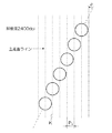
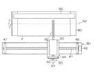
<1> 架橋レリーフ形成層を有するレリーフ印刷版原版を準備する工程、及び、前記レリーフ印刷版原版をレーザー彫刻する彫刻工程を含み、前記架橋レリーフ形成層は、(成分A)バインダーポリマー、及び、(成分B)光熱変換剤を含有するレリーフ形成層を架橋したものであり、前記成分Bの含有量が、レリーフ形成層の全固形分に対して0.1重量%以上であり、前記彫刻工程が、波長が700nm〜1,300nmの半導体レーザーを少なくとも2つ以上並べた露光ヘッドを用いて彫刻する工程であり、前記彫刻工程において、レーザー照射部に対して10m/s以上の風速で気体を吹き付け、且つ、前記気体の吹き付け角度は、版面に対して平行且つ描画方向と反対の角度を0°としたとき、0°以上90°未満であることを特徴とするレリーフ印刷版の製版方法、
<2> 前記架橋レリーフ形成層の架橋密度が10×102mol/mL以上である、<1>に記載のレリーフ印刷版の製版方法、
<3> 前記成分Bが、吸油量が150mL/100g未満のカーボンブラック、並びに/又は、800nm〜1,200nmにピーク光吸収がある顔料及び/若しくは染料である、<1>又は<2>に記載のレリーフ印刷版の製版方法、
<4> 前記成分Bをレリーフ形成層の全固形分に対して0.1重量%以上15重量%以下含有する、<1>〜<3>のいずれか1つに記載のレリーフ印刷版の製版方法、
<5> 前記半導体レーザーが、ファイバー付き半導体レーザーである、<1>〜<4>のいずれか1つに記載のレリーフ印刷版の製版方法、
<6> <1>〜<5>のいずれか1つに記載の方法により得られるレリーフ印刷版。
The above-mentioned problems of the present invention have been solved by means described in the following <1> and <6>. It is described below together with <2> to <5> which are preferred embodiments.
<1> including a step of preparing a relief printing plate precursor having a crosslinked relief forming layer, and an engraving step of laser engraving the relief printing plate precursor, wherein the crosslinked relief forming layer comprises (Component A) a binder polymer, and (Component B) A relief forming layer containing a photothermal conversion agent is crosslinked, and the content of Component B is 0.1% by weight or more based on the total solid content of the relief forming layer, and the engraving step Is a step of engraving using an exposure head in which at least two semiconductor lasers having wavelengths of 700 nm to 1,300 nm are arranged, and in the engraving step, gas is blown at a wind speed of 10 m / s or more with respect to the laser irradiation portion. The spraying angle of the gas is 0 ° or more and less than 90 ° when the angle parallel to the printing plate and the angle opposite to the drawing direction is 0 °. A method for making a relief printing plate,
<2> The plate making method of the relief printing plate according to <1>, wherein the crosslink relief forming layer has a crosslink density of 10 × 10 2 mol / mL or more,
<3> The component B is carbon black having an oil absorption of less than 150 mL / 100 g and / or a pigment and / or dye having peak light absorption at 800 nm to 1,200 nm, <1> or <2> Plate-making method of the relief printing plate as described,
<4> The plate making of a relief printing plate according to any one of <1> to <3>, wherein the component B is contained in an amount of 0.1% by weight to 15% by weight with respect to the total solid content of the relief forming layer. Method,
<5> The method for making a relief printing plate according to any one of <1> to <4>, wherein the semiconductor laser is a fiber-attached semiconductor laser,
<6> A relief printing plate obtained by the method according to any one of <1> to <5>.
本発明によれば、生産性に優れ、高画質な画像を形成できるレリーフ印刷版の製版方法を提供することができた。更に、本発明によれば、前記製版方法により得られるレリーフ印刷版を提供することができた。 ADVANTAGE OF THE INVENTION According to this invention, it was excellent in productivity and the plate making method of the relief printing plate which can form a high quality image was able to be provided. Furthermore, according to the present invention, a relief printing plate obtained by the plate making method can be provided.
本発明のレリーフ印刷版の製版方法は、架橋レリーフ形成層を有するレリーフ印刷版原版を準備する工程、及び、前記レリーフ印刷版原版をレーザー彫刻する彫刻工程を含み、前記架橋レリーフ形成層は、(成分A)バインダーポリマー、及び、(成分B)光熱変換剤を含有するレリーフ形成層を架橋したものであり、前記成分Bの含有量が、レリーフ形成層の全固形分に対して0.1重量%以上であり、前記彫刻工程が、波長が700nm〜1,300nmの半導体レーザーを少なくとも2つ以上並べた露光ヘッドを用いて彫刻する工程であり、前記彫刻工程において、レーザー照射部に対して10m/s以上の風速で気体を吹き付け、且つ、前記気体の吹き付け角度は、版面に対して平行且つ描画方向と反対の角度を0°としたとき、0°以上90°未満であることを特徴とする。
なお、本発明において、数値範囲を表す「下限〜上限」の記載は、「下限以上、上限以下」を表し、「上限〜下限」の記載は、「上限以下、下限以上」を表す。すなわち、上限及び下限を含む数値範囲を表す。また、本発明において、「(成分A)バインダーポリマー」等を単に「成分A」又は「バインダーポリマー」等ともいう。
The plate-making method of the relief printing plate of the present invention includes a step of preparing a relief printing plate precursor having a crosslinked relief forming layer, and an engraving step of laser engraving the relief printing plate precursor, wherein the crosslinked relief forming layer comprises: A relief forming layer containing component A) a binder polymer and (component B) a photothermal conversion agent is cross-linked, and the content of the component B is 0.1 weight with respect to the total solid content of the relief forming layer. The engraving step is a step of engraving using an exposure head in which at least two semiconductor lasers having wavelengths of 700 nm to 1,300 nm are arranged, and in the engraving step, 10 m is applied to the laser irradiation portion. The gas is blown at a wind speed of at least / s, and the gas blowing angle is 0 ° when the angle parallel to the printing plate and the direction opposite to the drawing direction is 0 °. The angle is less than 90 °.
In the present invention, the description of “lower limit to upper limit” representing a numerical range represents “lower limit or higher and lower limit or lower”, and the description of “upper limit to lower limit” represents “lower limit or higher and lower limit or higher”. That is, it represents a numerical range including an upper limit and a lower limit. In the present invention, “(component A) binder polymer” or the like is also simply referred to as “component A” or “binder polymer” or the like.
また、本明細書では、レリーフ印刷版の説明に関し、レーザー彫刻に供する画像形成層としての、表面が平坦な層であり、且つ、未架橋の架橋性層をレリーフ形成層といい、前記レリーフ形成層を架橋した層を架橋レリーフ形成層といい、これをレーザー彫刻して表面に凹凸を形成した層をレリーフ層という。
また、本発明において、成分A及び成分Bを含むレーザー彫刻用樹脂組成物(以下、単に「樹脂組成物」ともいう。)から形成されたレリーフ形成層を熱架橋し、架橋レリーフ形成層を有する印刷版原版を得ることが好ましい。
以下、レリーフ印刷版原版のレリーフ形成層の構成成分について説明する。
Further, in the present specification, regarding the description of the relief printing plate, the image forming layer used for laser engraving is a flat surface and an uncrosslinked crosslinkable layer is referred to as a relief forming layer, A layer obtained by crosslinking the layers is referred to as a crosslinked relief forming layer, and a layer in which irregularities are formed on the surface by laser engraving is referred to as a relief layer.
In the present invention, a relief forming layer formed from a resin composition for laser engraving containing component A and component B (hereinafter also simply referred to as “resin composition”) is thermally crosslinked to have a crosslinked relief forming layer. It is preferable to obtain a printing plate precursor.
Hereinafter, components of the relief forming layer of the relief printing plate precursor will be described.
(成分A)バインダーポリマー
本発明において、(成分A)バインダーポリマーは、水不溶、且つ、炭素数1〜4のアルコールに可溶のバインダーポリマーであることが好ましい。
成分Aは、エチレン性不飽和結合、エポキシ基、アミノ基、(メタ)アクリロイル基、メルカプト基、又は、ヒドロキシル基(−OH)を有することが好ましく、これらの中でも、ヒドロキシル基(−OH)を有することがより好ましい。以下、前記いずれかの基を有するバインダーポリマーを、(成分A−1)特定ポリマーともいう。
(Component A) Binder Polymer In the present invention, the (Component A) binder polymer is preferably a water-insoluble binder polymer that is soluble in an alcohol having 1 to 4 carbon atoms.
Component A preferably has an ethylenically unsaturated bond, an epoxy group, an amino group, a (meth) acryloyl group, a mercapto group, or a hydroxyl group (—OH). Among these, a hydroxyl group (—OH) is preferably present. More preferably. Hereinafter, the binder polymer having any of the above groups is also referred to as (Component A-1) specific polymer.
〔(成分A−1)特定ポリマー〕
本発明における特定ポリマーとして、水性インキ適性とUVインキ適性を両立しつつ、且つ彫刻感度が高く皮膜性も良好であるという観点で、ポリビニルブチラール(PVB)誘導体、側鎖にヒドロキシル基を有するアクリル樹脂及び側鎖にヒドロキシル基を有するエポキシ樹脂等が好ましく例示される。
[(Component A-1) Specific polymer]
As a specific polymer in the present invention, a polyvinyl butyral (PVB) derivative and an acrylic resin having a hydroxyl group in a side chain from the viewpoint of achieving both water-based ink suitability and UV ink suitability, and high engraving sensitivity and good film properties. An epoxy resin having a hydroxyl group in the side chain and the like are preferably exemplified.
本発明に用い得る特定ポリマーは、本発明においてレリーフ形成層を構成する併用成分である、(成分B)光熱変換剤と組み合わせた場合に、ガラス転移温度(Tg)が20℃以上のものとすることで、彫刻感度が向上するため、特に好ましい。このようなガラス転移温度を有するポリマーを以下、非エラストマーと称する。即ち、エラストマーとは、一般的に、ガラス転移温度が常温以下のポリマーであるとして学術的に定義されている(科学大辞典 第2版、編者 国際科学振興財団、発行 丸善(株)、P154参照)。従って、非エラストマーとはガラス転移温度が常温を超える温度であるポリマーを指す。特定ポリマーのガラス転移温度の上限には制限はないが、200℃以下であることが取り扱い性の観点から好ましく、25℃以上120℃以下であることがより好ましい。 The specific polymer that can be used in the present invention has a glass transition temperature (Tg) of 20 ° C. or higher when combined with a (component B) photothermal conversion agent, which is a combined component constituting the relief forming layer in the present invention. This is particularly preferable because the engraving sensitivity is improved. Hereinafter, a polymer having such a glass transition temperature is referred to as a non-elastomer. That is, an elastomer is generally defined scientifically as a polymer having a glass transition temperature of room temperature or lower (see Science Dictionaries 2nd Edition, Editor International Science Promotion Foundation, published by Maruzen Co., Ltd., P154). ). Therefore, a non-elastomer refers to a polymer having a glass transition temperature exceeding normal temperature. Although there is no restriction | limiting in the upper limit of the glass transition temperature of a specific polymer, it is preferable from a viewpoint of handleability that it is 200 degrees C or less, and it is more preferable that it is 25 degreeC or more and 120 degrees C or less.
ガラス転移温度が室温(20℃)以上のポリマーを用いる場合、特定ポリマーは常温ではガラス状態をとる。このためゴム状態をとる場合に比較して、熱的な分子運動はかなり抑制された状態にある。レーザー彫刻においては、レーザー照射時に、赤外線レーザーが付与する熱に加え、(成分B)光熱変換剤の機能により発生した熱が、周囲に存在する特定ポリマーに伝達され、これが熱分解、消散して、結果的に彫刻されて凹部が形成される。
本発明では、特定ポリマーの熱的な分子運動が抑制された状態の中に光熱変換剤が存在すると、特定ポリマーへの熱伝達と熱分解が効果的に起こるものと考えられ、このような効果によって彫刻感度が更に増大したものと推定される。
When a polymer having a glass transition temperature of room temperature (20 ° C.) or higher is used, the specific polymer takes a glass state at room temperature. For this reason, the thermal molecular motion is considerably suppressed as compared with the rubber state. In laser engraving, in addition to the heat imparted by the infrared laser during laser irradiation, the heat generated by the function of the (component B) photothermal conversion agent is transferred to the surrounding specific polymer, which decomposes and dissipates. As a result, engraving is performed to form a recess.
In the present invention, when a photothermal conversion agent is present in a state in which the thermal molecular motion of a specific polymer is suppressed, it is considered that heat transfer and thermal decomposition to the specific polymer occur effectively. It is estimated that the engraving sensitivity has further increased.
本発明において好ましく用いられる特定ポリマーの特に好ましい態様である非エラストマーであるポリマーの具体例を以下に挙げる。 Specific examples of the non-elastomer polymer which is a particularly preferable embodiment of the specific polymer preferably used in the present invention are given below.
(1)ポリビニルアセタール及びその誘導体
ポリビニルアセタールは、ポリビニルアルコール(ポリ酢酸ビニルを鹸化して得られる)を環状アセタール化することにより得られる化合物である。また、ポリビニルアセタール誘導体は、前記ポリビニルアセタールを変性させたり、他の共重合成分を加えたものである。
ポリビニルアセタール中のアセタール含量(原料の酢酸ビニルモノマーの総モル数を100%とし、アセタール化されるビニルアルコール単位のモル%)は、30%〜90%が好ましく、50%〜85%がより好ましく、55%〜78%が特に好ましい。
ポリビニルアセタール中のビニルアルコール単位としては、原料の酢酸ビニルモノマーの総モル数に対して、10モル%〜70モル%が好ましく、15モル%〜50モル%がより好ましく、22モル%〜45モル%が特に好ましい。
また、ポリビニルアセタールは、その他の成分として、酢酸ビニル単位を有していてもよく、その含量としては0.01〜20モル%が好ましく、0.1〜10モル%が更に好ましい。ポリビニルアセタール誘導体は、更に、その他の共重合単位を有していてもよい。
ポリビニルアセタールとしては、ポリビニルブチラール、ポリビニルプロピラール、ポリビニルエチラール、ポリビニルメチラールなどが挙げられ、中でもポリビニルブチラール(以下、PVBと称する。)が好ましい。
ポリビニルブチラールは、通常、ポリビニルアルコールをブチラール化して得られるポリマーである。また、ポリビニルブチラール誘導体を用いてもよい。
ポリビニルブチラール誘導体の例として、水酸基の少なくとも一部をカルボキシル基等の酸基に変性した酸変性PVB、水酸基の一部を(メタ)アクリロイル基に変性した変性PVB、水酸基の少なくとも一部をアミノ基に変性した変性PVB、水酸基の少なくとも一部にエチレングリコールやプロピレングリコール及びこれらの複量体を導入した変性PVB等が挙げられる。
ポリビニルアセタールの分子量としては、彫刻感度と皮膜性のバランスを保つ観点で、重量平均分子量として5,000〜800,000であることが好ましく、より好ましくは8,000〜500,000である。更に、彫刻カスのリンス性向上の観点からは、50,000〜300,000であることが特に好ましい。
(1) Polyvinyl acetal and derivatives thereof Polyvinyl acetal is a compound obtained by cyclic acetalization of polyvinyl alcohol (obtained by saponifying polyvinyl acetate). Further, the polyvinyl acetal derivative is obtained by modifying the polyvinyl acetal or adding another copolymer component.
The acetal content in the polyvinyl acetal (mole% of vinyl alcohol units to be acetalized with the total number of moles of the starting vinyl acetate monomer being 100%) is preferably 30% to 90%, more preferably 50% to 85%. 55% to 78% is particularly preferable.
The vinyl alcohol unit in the polyvinyl acetal is preferably 10 mol% to 70 mol%, more preferably 15 mol% to 50 mol%, more preferably 22 mol% to 45 mol, based on the total number of moles of the raw material vinyl acetate monomer. % Is particularly preferred.
Moreover, the polyvinyl acetal may have a vinyl acetate unit as another component, and the content thereof is preferably 0.01 to 20 mol%, more preferably 0.1 to 10 mol%. The polyvinyl acetal derivative may further have other copolymer units.
Examples of the polyvinyl acetal include polyvinyl butyral, polyvinyl propylal, polyvinyl ethylal, and polyvinyl methylal. Among them, polyvinyl butyral (hereinafter referred to as PVB) is preferable.
Polyvinyl butyral is usually a polymer obtained by converting polyvinyl alcohol into butyral. A polyvinyl butyral derivative may also be used.
Examples of polyvinyl butyral derivatives include acid-modified PVB in which at least part of the hydroxyl group is modified to an acid group such as a carboxyl group, modified PVB in which part of the hydroxyl group is modified to a (meth) acryloyl group, and at least part of the hydroxyl group is an amino group. Modified PVB, modified PVB in which ethylene glycol, propylene glycol, or a multimer thereof is introduced into at least a part of the hydroxyl group.
The molecular weight of the polyvinyl acetal is preferably 5,000 to 800,000, more preferably 8,000 to 500,000 as a weight average molecular weight from the viewpoint of maintaining a balance between engraving sensitivity and film property. Further, from the viewpoint of improving the rinse performance of engraving residue, it is particularly preferably 50,000 to 300,000.
以下、ポリビニルアセタールの特に好ましい例として、ポリビニルブチラール(PVB)及びその誘導体を挙げて説明するが、これに限定されない。
PVBとしては、市販品としても入手可能であり、その好ましい具体例としては、アルコール溶解性(特にエタノール溶解性)の観点で、積水化学工業(株)製の「エスレックB」シリーズ、「エスレックK(KS)」シリーズ、電気化学工業(株)製の「デンカブチラール」が好ましい。更に好ましくは、アルコール溶解性(特にエタノール)の観点で積水化学工業(株)製の「エスレックB」シリーズと電気化学工業(株)製の「デンカブチラール」であり、特に好ましくは「エスレックB」シリーズでは、「BL−1」、「BL−1H」、「BL−2」、「BL−5」、「BL−S」、「BX−L」、「BM−S」、「BH−S」、電気化学工業(株)製の「デンカブチラール」では「#3000−1」、「#3000−2」、「#3000−4」、「#4000−2」、「#6000−C」、「#6000−EP」、「#6000−CS」、「#6000−AS」である。
PVBを特定ポリマーとして用いてレリーフ形成層を製膜する際には、溶媒に溶かした溶液をキャストし乾燥させる方法が、膜の表面の平滑性の観点で好ましい。
Hereinafter, although polyvinyl butyral (PVB) and its derivative (s) are mentioned and demonstrated as a particularly preferable example of polyvinyl acetal, it is not limited to this.
As PVB, it can also be obtained as a commercial product, and preferred specific examples thereof include “ESREC B” series and “ESREC K” manufactured by Sekisui Chemical Co., Ltd. from the viewpoint of alcohol solubility (particularly ethanol solubility). (KS) "series," Denkabutyral "manufactured by Denki Kagaku Kogyo Co., Ltd. are preferred. More preferably, from the viewpoint of alcohol solubility (especially ethanol), “S Lec B” series manufactured by Sekisui Chemical Co., Ltd. and “Denka Butyral” manufactured by Denki Kagaku Kogyo Co., Ltd. are particularly preferable. In the series, “BL-1”, “BL-1H”, “BL-2”, “BL-5”, “BL-S”, “BX-L”, “BM-S”, “BH-S” In “Denka Butyral” manufactured by Denki Kagaku Kogyo Co., Ltd., “# 3000-1”, “# 3000-2”, “# 3000-4”, “# 4000-2”, “# 6000-C”, “ # 6000-EP ","# 6000-CS ", and"# 6000-AS ".
When a relief forming layer is formed using PVB as a specific polymer, a method in which a solution dissolved in a solvent is cast and dried is preferable from the viewpoint of the smoothness of the surface of the membrane.
(2)アクリル樹脂
本発明における特定ポリマーとして用い得るアクリル樹脂としては、公知のアクリル単量体を用いて得られるアクリル樹脂であって、分子内にヒドロキシル基を有するものであれば用いることができる。
ヒドロキシル基を有するアクリル樹脂の合成に用いられるアクリル単量体としては、例えば(メタ)アクリル酸エステル類、クロトン酸エステル類(メタ)アクリルアミド類であって分子内にヒドロキシル基を有するものが好ましい。この様な単量体の具体例としては例えば、2−ヒドロキシエチル(メタ)アクリレート、2−ヒドロキシプロピル(メタ)アクリレート、4−ヒドロキシブチル(メタ)アクリレート等が挙げられる。
(2) Acrylic resin The acrylic resin that can be used as the specific polymer in the present invention is an acrylic resin obtained by using a known acrylic monomer, and any acrylic resin having a hydroxyl group in the molecule can be used. .
As the acrylic monomer used for the synthesis of the acrylic resin having a hydroxyl group, for example, (meth) acrylic acid esters and crotonic acid esters (meth) acrylamides having a hydroxyl group in the molecule are preferable. Specific examples of such a monomer include 2-hydroxyethyl (meth) acrylate, 2-hydroxypropyl (meth) acrylate, 4-hydroxybutyl (meth) acrylate, and the like.
また、アクリル樹脂としては、上記ヒドロキシル基を有するアクリル単量体以外のアクリル単量体を共重合成分として含むこともできる。このようなアクリル単量体としては、(メタ)アクリル酸エステル類としては、メチル(メタ)アクリレート、エチル(メタ)アクリレート、n−プロピル(メタ)アクリレート、イソプロピル(メタ)アクリレート、n−ブチル(メタ)アクリレート、イソブチル(メタ)アクリレート、tert−ブチル(メタ)アクリレート、n−ヘキシル(メタ)アクリレート、2−エチルヘキシル(メタ)アクリレート、アセトキシエチル(メタ)アクリレート、フェニル(メタ)アクリレート、2−メトキシエチル(メタ)アクリレート、2−エトキシエチル(メタ)アクリレート、2−(2−メトキシエトキシ)エチル(メタ)アクリレート、シクロヘキシル(メタ)アクリレート、ベンジル(メタ)アクリレート、ジエチレングリコールモノメチルエーテル(メタ)アクリレート、ジエチレングリコールモノエチルエーテル(メタ)アクリレート、ジエチレングリコールモノフェニルエーテル(メタ)アクリレート、トリエチレングリコールモノメチルエーテル(メタ)アクリレート、トリエチレングリコールモノエチルエーテル(メタ)アクリレート、ジプロピレングリコールモノメチルエーテル(メタ)アクリレート、ポリエチレングリコールモノメチルエーテル(メタ)アクリレート、ポリプロピレングリコールモノメチルエーテル(メタ)アクリレート、エチレングリコールとプロピレングリコールとの共重合体のモノメチルエーテル(メタ)アクリレート、N,N−ジメチルアミノエチル(メタ)アクリレート、N,N−ジエチルアミノエチル(メタ)アクリレート、N,N−ジメチルアミノプロピル(メタ)アクリレート等が挙げられる。
更に、ウレタン結合やウレア結合を有するアクリル単量体を含んで構成される変性アクリル樹脂も好ましく使用することができる。
これらの中でも、水性インキ耐性の観点で、ラウリル(メタ)アクリレートなどのアルキル(メタ)アクリレート類、t−ブチルシクロヘキシルメタクリレートなど脂肪族環状構造を有する(メタ)アクリレート類が特に好ましい。
Moreover, as an acrylic resin, acrylic monomers other than the acrylic monomer which has the said hydroxyl group can also be included as a copolymerization component. Examples of such acrylic monomers include (meth) acrylic acid esters such as methyl (meth) acrylate, ethyl (meth) acrylate, n-propyl (meth) acrylate, isopropyl (meth) acrylate, n-butyl ( (Meth) acrylate, isobutyl (meth) acrylate, tert-butyl (meth) acrylate, n-hexyl (meth) acrylate, 2-ethylhexyl (meth) acrylate, acetoxyethyl (meth) acrylate, phenyl (meth) acrylate, 2-methoxy Ethyl (meth) acrylate, 2-ethoxyethyl (meth) acrylate, 2- (2-methoxyethoxy) ethyl (meth) acrylate, cyclohexyl (meth) acrylate, benzyl (meth) acrylate, diethylene glycol mono Tyl ether (meth) acrylate, diethylene glycol monoethyl ether (meth) acrylate, diethylene glycol monophenyl ether (meth) acrylate, triethylene glycol monomethyl ether (meth) acrylate, triethylene glycol monoethyl ether (meth) acrylate, dipropylene glycol monomethyl ether (Meth) acrylate, polyethylene glycol monomethyl ether (meth) acrylate, polypropylene glycol monomethyl ether (meth) acrylate, monomethyl ether (meth) acrylate of a copolymer of ethylene glycol and propylene glycol, N, N-dimethylaminoethyl (meta ) Acrylate, N, N-diethylaminoethyl (meth) acrylate, N N- dimethylaminopropyl (meth) acrylate.
Furthermore, a modified acrylic resin comprising an acrylic monomer having a urethane bond or a urea bond can also be preferably used.
Among these, alkyl (meth) acrylates such as lauryl (meth) acrylate and (meth) acrylates having an aliphatic cyclic structure such as t-butylcyclohexyl methacrylate are particularly preferable from the viewpoint of water-based ink resistance.
また、特定ポリマーとして、フェノール類とアルデヒド類を酸性条件下で縮合させた樹脂であるノボラック樹脂を用いることができる。
好ましいノボラック樹脂としては、例えばフェノールとホルムアルデヒドから得られるノボラック樹脂、m−クレゾールとホルムアルデヒドから得られるノボラック樹脂、p−クレゾールとホルムアルデヒドから得られるノボラック樹脂、o−クレゾールとホルムアルデヒドから得られるノボラック樹脂、オクチルフェノールとホルムアルデヒドから得られるノボラック樹脂、m−/p−混合クレゾールとホルムアルデヒドから得られるノボラック樹脂、フェノール/クレゾール(m−,p−,o−又はm−/p−,m−/o−,o−/p−混合のいずれでもよい)の混合物とホルムアルデヒドから得られるノボラック樹脂などが挙げられる。
これらのノボラック樹脂は、重量平均分子量が800〜200,000で、数平均分子量が400〜60,000のものが好ましい。
特定ポリマーとして、ヒドロキシル基を側鎖に有するエポキシ樹脂を用いることも可能である。好ましい具体例としては、ビスフェノールAとエピクロロヒドリンの付加物を原料モノマーとして重合して得られるエポキシ樹脂が好ましい。
これらのエポキシ樹脂は、重量平均分子量が800〜200,000で、数平均分子量が400〜60,000のものが好ましい。
Moreover, novolak resin which is resin which condensed phenols and aldehydes on acidic conditions can be used as a specific polymer.
Preferred novolak resins include, for example, novolak resins obtained from phenol and formaldehyde, novolak resins obtained from m-cresol and formaldehyde, novolak resins obtained from p-cresol and formaldehyde, novolak resins obtained from o-cresol and formaldehyde, and octylphenol. And novolak resins obtained from formaldehyde, m- / p-mixed cresol and novolak resins obtained from formaldehyde, phenol / cresol (m-, p-, o- or m- / p-, m- / o-, o- / P-mixed) and a novolak resin obtained from formaldehyde.
These novolak resins preferably have a weight average molecular weight of 800 to 200,000 and a number average molecular weight of 400 to 60,000.
It is also possible to use an epoxy resin having a hydroxyl group in the side chain as the specific polymer. As a preferable specific example, an epoxy resin obtained by polymerizing an adduct of bisphenol A and epichlorohydrin as a raw material monomer is preferable.
These epoxy resins preferably have a weight average molecular weight of 800 to 200,000 and a number average molecular weight of 400 to 60,000.
特定ポリマーの中でも、レリーフ形成層及び架橋レリーフ形成層としたときのリンス性及び耐刷性の観点でポリビニルブチラール及びその誘導体が特に好ましい。
本発明における特定ポリマーに含まれるヒドロキシル基の含有量は、前記いずれの態様のポリマーにおいても、0.1〜15mmol/gであることが好ましく、0.5〜7mmol/gであることがより好ましい。
本発明において、レーザー彫刻用樹脂組成物には特定ポリマーを1種のみ用いてもよく、2種以上を併用してもよい。
本発明に用いることができる特定ポリマーの重量平均分子量(GPC測定によるポリスチレン換算)は、5,000〜1,000,000であることが好ましく、8,000〜750,000であることがより好ましく、10,000〜500,000であることが更に好ましい。
本発明に用い得るレーザー彫刻用樹脂組成物における特定ポリマーの好ましい含有量は、塗膜の形態保持性と耐水性と彫刻感度をバランスよく満足する観点で、全固形分中、2〜95重量%であることが好ましく、より好ましくは5〜80重量%、特に好ましくは10〜60重量%である。
Among the specific polymers, polyvinyl butyral and derivatives thereof are particularly preferable from the viewpoint of rinsing properties and printing durability when used as a relief forming layer and a crosslinked relief forming layer.
The content of the hydroxyl group contained in the specific polymer in the present invention is preferably 0.1 to 15 mmol / g, more preferably 0.5 to 7 mmol / g in any of the above-described polymers. .
In the present invention, only one type of specific polymer may be used in the resin composition for laser engraving, or two or more types may be used in combination.
The weight average molecular weight of the specific polymer that can be used in the present invention (polystyrene conversion by GPC measurement) is preferably 5,000 to 1,000,000, and more preferably 8,000 to 750,000. More preferably, it is 10,000 to 500,000.
The preferable content of the specific polymer in the resin composition for laser engraving that can be used in the present invention is 2 to 95% by weight in the total solid content from the viewpoint of satisfying a good balance of form retention, water resistance and engraving sensitivity. More preferably, it is 5 to 80% by weight, particularly preferably 10 to 60% by weight.
〔(成分A−2)併用ポリマー〕
本発明において、レーザー彫刻用樹脂組成物には、(成分A)バインダーポリマーとして、上記(成分A−1)特定ポリマーに加え、ヒドロキシル基を有しないポリマーなど(成分A−1)特定ポリマーに包含されない公知のポリマーを併用することができる。以下、このようなポリマーを(成分A−2)併用ポリマーと称する。
併用ポリマーは、前記特定ポリマーとともに、レーザー彫刻用樹脂組成物に含有される主成分を構成するものであり、特定ポリマーに包含されない一般的な高分子化合物を適宜選択し、1種又は2種以上を併用して用いることができる。特に、レリーフ印刷版原版に用いる際は、レーザー彫刻性、インキ受与性、彫刻カス分散性などの種々の性能を考慮して選択することが必要である。
[(Component A-2) Combined Polymer]
In the present invention, the resin composition for laser engraving includes (Component A) as a binder polymer, in addition to the above (Component A-1) specific polymer, a polymer having no hydroxyl group, etc. (Component A-1) as a specific polymer Not known polymers can be used in combination. Hereinafter, such a polymer is referred to as (Component A-2) combined use polymer.
The combined polymer constitutes the main component contained in the resin composition for laser engraving together with the specific polymer, and a general polymer compound not included in the specific polymer is appropriately selected, and one or two or more types are used. Can be used in combination. In particular, when used for a relief printing plate precursor, it is necessary to select in consideration of various performances such as laser engraving property, ink acceptability, and engraving residue dispersibility.
併用ポリマーとしては、ポリスチレン樹脂、ポリエステル樹脂、ポリアミド樹脂、ポリウレアポリアミドイミド樹脂、ポリウレタン樹脂、ポリスルホン樹脂、ポリエーテルスルホン樹脂、ポリイミド樹脂、ポリカーボネート樹脂、ヒドロキシエチレン単位を含む親水性ポリマー、アクリル樹脂、ポリカーボネート樹脂、ゴム、熱可塑性エラストマーなどから選択して用いることができる。 As the polymer used, polystyrene resin, polyester resin, polyamide resin, polyurea polyamideimide resin, polyurethane resin, polysulfone resin, polyethersulfone resin, polyimide resin, polycarbonate resin, hydrophilic polymer containing hydroxyethylene unit, acrylic resin, polycarbonate resin , Rubber, thermoplastic elastomer and the like.
例えば、レーザー彫刻感度の観点からは、露光又は加熱により熱分解する部分構造を含むポリマーが好ましい。このようなポリマーは、特開2008−163081号公報[0038]に記載されているものが好ましく挙げられる。また、例えば、柔軟で可撓性を有する膜形成が目的とされる場合には、軟質樹脂や熱可塑性エラストマーが選択される。特開2008−163081号公報[0039]〜[0040]に詳述されている。更に、レリーフ形成層用組成物の調製の容易性、得られたレリーフ印刷版における油性インクに対する耐性向上の観点から、親水性又は親アルコール性ポリマーを使用することが好ましい。親水性ポリマーとしては、特開2008−163081号公報[0041]に詳述されているものを使用することができる。 For example, from the viewpoint of laser engraving sensitivity, a polymer containing a partial structure that is thermally decomposed by exposure or heating is preferable. Preferred examples of such a polymer include those described in JP 2008-163081 A [0038]. For example, when the purpose is to form a soft and flexible film, a soft resin or a thermoplastic elastomer is selected. JP-A-2008-163081 discloses details in [0039] to [0040]. Furthermore, it is preferable to use a hydrophilic or alcoholic polymer from the viewpoint of easy preparation of the composition for a relief forming layer and improvement in resistance to oil-based ink in the obtained relief printing plate. As the hydrophilic polymer, those described in detail in JP 2008-163081 A [0041] can be used.
また、ポリ乳酸などのヒドロキシカルボン酸ユニットからなるポリエステルを好ましく用いることができる。このようなポリエステルとしては、具体的には、ポリヒドロキシアルカノエート(PHA)、乳酸系ポリマー、ポリグリコール酸(PGA)、ポリカプロラクトン(PCL)、ポリ(ブチレンコハク酸)、これらの誘導体又は混合物から成る群から選択されるものが好ましい。 In addition, polyesters composed of hydroxycarboxylic acid units such as polylactic acid can be preferably used. Specific examples of such polyesters include polyhydroxyalkanoate (PHA), lactic acid-based polymer, polyglycolic acid (PGA), polycaprolactone (PCL), poly (butylene succinic acid), and derivatives or mixtures thereof. Those selected from the group consisting of are preferred.
加えて、加熱や露光により硬化させ、強度を向上させる目的に使用する場合には、分子内に炭素−炭素不飽和結合をもつポリマーが好ましく用いられる。
このようなポリマーとして、主鎖に炭素−炭素不飽和結合を含むポリマーとしては、例えば、SB(ポリスチレン−ポリブタジエン)、SBS(ポリスチレン−ポリブタジエン−ポリスチレン)、SIS(ポリスチレン−ポリイソプレン−ポリスチレン)、SEBS(ポリスチレン−ポリエチレン/ポリブチレン−ポリスチレン)等が挙げられる。
In addition, when used for the purpose of curing by heating or exposure and improving the strength, a polymer having a carbon-carbon unsaturated bond in the molecule is preferably used.
Examples of such a polymer that includes a carbon-carbon unsaturated bond in the main chain include SB (polystyrene-polybutadiene), SBS (polystyrene-polybutadiene-polystyrene), SIS (polystyrene-polyisoprene-polystyrene), and SEBS. (Polystyrene-polyethylene / polybutylene-polystyrene) and the like.
側鎖に炭素−炭素不飽和結合をもつポリマーとしては、前記の本発明で適用可能なバインダーポリマーの骨格に、アリル基、アクリロイル基、メタクリロイル基、スチリル基、ビニルエーテル基のような炭素−炭素不飽和結合を側鎖に導入することで得られる。バインダーポリマー側鎖に炭素−炭素不飽和結合を導入する方法は、重合性基に保護基を結合させてなる重合性基前駆体を有する構造単位をポリマーに共重合させ、保護基を脱離させて重合性基とする方法、水酸基、アミノ基、エポキシ基、カルボキシル基などの反応性基を複数有する高分子化合物を作製し、これらの反応性基と反応する基及び炭素−炭素不飽和結合を有する化合物を高分子反応させて導入する方法など、公知の方法をとることができる。これらの方法によれば、高分子化合物中への不飽和結合、重合性基の導入量を制御することができる。
このように、レリーフ印刷版の適用用途に応じた物性を考慮し、目的に応じた併用ポリマーを選択し、当該併用ポリマーの1種を、又は、2種以上を組み合わせて用いることができる。
Examples of the polymer having a carbon-carbon unsaturated bond in the side chain include carbon-carbon unsaturated groups such as an allyl group, an acryloyl group, a methacryloyl group, a styryl group, and a vinyl ether group in the skeleton of the binder polymer applicable in the present invention. It is obtained by introducing a saturated bond into the side chain. In the method of introducing a carbon-carbon unsaturated bond into the side chain of the binder polymer, a structural unit having a polymerizable group precursor formed by bonding a protective group to a polymerizable group is copolymerized with the polymer, and the protective group is eliminated. To prepare a polymer compound having a plurality of reactive groups such as a hydroxyl group, an amino group, an epoxy group, and a carboxyl group, and to react with these reactive groups and a carbon-carbon unsaturated bond. A known method such as a method of introducing the compound having a polymer reaction by polymer reaction can be employed. According to these methods, the amount of unsaturated bonds and polymerizable groups introduced into the polymer compound can be controlled.
As described above, in consideration of the physical properties according to the application application of the relief printing plate, a combination polymer can be selected according to the purpose, and one type of the combination polymer or a combination of two or more types can be used.
本発明における併用ポリマーの重量平均分子量(GPC測定によるポリスチレン換算)は、0.5万〜50万が好ましい。重量平均分子量が0.5万以上であれば、単体樹脂としての形態保持性に優れ、50万以下であれば、水など溶媒に溶解しやすくレリーフ形成層を調製するのに好都合である。併用ポリマーの重量平均分子量は、より好ましくは1万〜40万、特に好ましくは1.5万〜30万である。 The weight average molecular weight (in terms of polystyrene by GPC measurement) of the combined polymer in the present invention is preferably from 50,000 to 500,000. If the weight average molecular weight is 50,000 or more, the form retainability as a single resin is excellent, and if it is 500,000 or less, it is easy to dissolve in a solvent such as water, which is convenient for preparing a relief forming layer. The weight average molecular weight of the combined use polymer is more preferably 10,000 to 400,000, and particularly preferably 15,000 to 300,000.
バインダーポリマーの総含有量〔(成分A−1)特定ポリマーと(成分A−2)併用ポリマーとの合計含有量〕は、レーザー彫刻用樹脂組成物の固形分全重量に対し、5重量%〜95重量%が好ましく、15重量%〜80重量%がより好ましく、20重量%〜65重量%が更に好ましい。
例えば、レーザー彫刻用樹脂組成物をレリーフ印刷版原版のレリーフ形成層に適用した場合、バインダーポリマーの含有量を5重量%以上とすることで、得られたレリーフ印刷版を印刷版として使用するに足る耐刷性が得られ、また、95重量%以下とすることで、他成分が不足することがなく、レリーフ印刷版をフレキソ印刷版とした際においても印刷版として使用するに足る柔軟性を得ることができる。
The total content of the binder polymer [the total content of the (component A-1) specific polymer and the (component A-2) combined polymer] is 5% by weight to the total solid content of the resin composition for laser engraving. 95 weight% is preferable, 15 weight%-80 weight% is more preferable, and 20 weight%-65 weight% is still more preferable.
For example, when the resin composition for laser engraving is applied to the relief forming layer of the relief printing plate precursor, the resulting relief printing plate can be used as a printing plate by setting the binder polymer content to 5% by weight or more. Insufficient printing durability is obtained, and by making it 95% by weight or less, other components are not deficient, and flexibility sufficient to be used as a printing plate even when a relief printing plate is used as a flexographic printing plate. Obtainable.
(成分B)光熱変換剤
本発明において、レリーフ形成層は、(成分B)光熱変換剤を含有する。光熱変換剤は、レーザーの光を吸収し発熱することで、レーザー彫刻用樹脂組成物の硬化物の熱分解を促進すると考えられる。ゆえに、彫刻に用いるレーザー波長の光を吸収する光熱変換剤を選択することが好ましい。
(Component B) Photothermal Conversion Agent In the present invention, the relief forming layer contains (Component B) a photothermal conversion agent. It is considered that the photothermal conversion agent promotes thermal decomposition of the cured product of the resin composition for laser engraving by absorbing laser light and generating heat. Therefore, it is preferable to select a photothermal conversion agent that absorbs light having a laser wavelength used for engraving.
本発明において、波長700nm〜1,300nmの赤外線を発する半導体レーザーを光源としてレーザー彫刻に用いるので、本発明におけるレリーフ形成層は、700nm〜1,300nmの波長の光を吸収可能な光熱変換剤を含有することが好ましい。
本発明における光熱変換剤としては、種々の染料又は顔料が用いられる。
前記光熱変換剤は、吸油量が150mL/100g未満のカーボンブラック、並びに/又は、800nm〜1,200nmに吸収を有する顔料及び/又は染料から選択される1種以上の光熱変換剤であることがより好ましい。
また、前記光熱変換剤は、顔料であることが好ましい。
In the present invention, a semiconductor laser emitting an infrared ray having a wavelength of 700 nm to 1,300 nm is used as a light source for laser engraving. Therefore, the relief forming layer in the present invention is a photothermal conversion agent capable of absorbing light having a wavelength of 700 nm to 1,300 nm. It is preferable to contain.
Various dyes or pigments are used as the photothermal conversion agent in the present invention.
The photothermal conversion agent may be one or more photothermal conversion agents selected from carbon black having an oil absorption of less than 150 mL / 100 g and / or pigments and / or dyes having absorption at 800 nm to 1,200 nm. More preferred.
The photothermal conversion agent is preferably a pigment.
光熱変換剤のうち、染料としては、市販の染料及び例えば「染料便覧」(有機合成化学協会編集、昭和45年刊)等の文献に記載されている公知のものが利用できる。具体的には、700nm〜1,300nmに極大吸収波長を有するものが挙げられ、アゾ染料、金属錯塩アゾ染料、ピラゾロンアゾ染料、ナフトキノン染料、アントラキノン染料、フタロシアニン染料、カルボニウム染料、ジインモニウム化合物、キノンイミン染料、メチン染料、シアニン染料、スクワリリウム色素、ピリリウム塩、金属チオレート錯体等の染料が挙げられる。特に、ヘプタメチンシアニン色素等のシアニン系色素、ペンタメチンオキソノール色素等のオキソノール系色素、フタロシアニン系色素が好ましく用いられる。例えば、特開2008−63554号公報の段落[0124]〜[0137]に記載の染料を挙げることができる。 Among the photothermal conversion agents, as the dye, commercially available dyes and known ones described in documents such as “Dye Handbook” (edited by the Society for Synthetic Organic Chemistry, published in 1970) can be used. Specific examples include those having a maximum absorption wavelength at 700 nm to 1,300 nm. Azo dyes, metal complex azo dyes, pyrazolone azo dyes, naphthoquinone dyes, anthraquinone dyes, phthalocyanine dyes, carbonium dyes, diimmonium compounds, quinone imine dyes , Methine dyes, cyanine dyes, squarylium dyes, pyrylium salts, and metal thiolate complexes. In particular, cyanine dyes such as heptamethine cyanine dye, oxonol dyes such as pentamethine oxonol dye, and phthalocyanine dyes are preferably used. Examples thereof include the dyes described in paragraphs [0124] to [0137] of JP-A-2008-63554.
本発明において使用される光熱変換剤のうち、顔料としては、市販の顔料及びカラーインデックス(C.I.)便覧、「最新顔料便覧」(日本顔料技術協会編、1977年刊)、「最新顔料応用技術」(CMC出版、1986年刊)、「印刷インキ技術」CMC出版、1984年刊)に記載されている顔料が利用できる。 Among the photothermal conversion agents used in the present invention, commercially available pigments and color index (CI) manuals, “latest pigment manuals” (edited by the Japan Pigment Technical Association, published in 1977), “latest pigment application” The pigments described in “Technology” (CMC Publishing, 1986) and “Printing Ink Technology” CMC Publishing, 1984) can be used.
顔料の種類としては、黒色顔料、黄色顔料、オレンジ色顔料、褐色顔料、赤色顔料、紫色顔料、青色顔料、緑色顔料、蛍光顔料、金属粉顔料、その他、ポリマー結合色素が挙げられる。具体的には、不溶性アゾ顔料、アゾレーキ顔料、縮合アゾ顔料、キレートアゾ顔料、フタロシアニン系顔料、アントラキノン系顔料、ペリレン及びペリノン系顔料、チオインジゴ系顔料、キナクリドン系顔料、ジオキサジン系顔料、イソインドリノン系顔料、キノフタロン系顔料、染付けレーキ顔料、アジン顔料、ニトロソ顔料、ニトロ顔料、天然顔料、蛍光顔料、無機顔料、カーボンブラック等が使用できる。これらの顔料のうち好ましいものはカーボンブラックである。 Examples of the pigment include black pigments, yellow pigments, orange pigments, brown pigments, red pigments, purple pigments, blue pigments, green pigments, fluorescent pigments, metal powder pigments, and other polymer-bonded dyes. Specifically, insoluble azo pigments, azo lake pigments, condensed azo pigments, chelate azo pigments, phthalocyanine pigments, anthraquinone pigments, perylene and perinone pigments, thioindigo pigments, quinacridone pigments, dioxazine pigments, isoindolinone pigments In addition, quinophthalone pigments, dyed lake pigments, azine pigments, nitroso pigments, nitro pigments, natural pigments, fluorescent pigments, inorganic pigments, carbon black, and the like can be used. Among these pigments, carbon black is preferable.
本発明における光熱変換剤としては、安定性、光熱変換効率の観点からカーボンブラックを好ましく挙げることができる。カーボンブラックは、レリーフ形成層を構成する組成物中における分散安定性などに問題がない限り、ASTMにより分類される規格の製品以外でも、カラー用、ゴム用、乾電池用などの各種用途に通常使用されるいずれのカーボンブラックも使用可能である。
ここでいうカーボンブラックには、例えば、ファーネスブラック、サーマルブラック、チャンネルブラック、ランプブラック、アセチレンブラックなども包含される。なお、カーボンブラックなどの黒色着色剤は、分散を容易にするため、必要に応じて分散剤を用い、予めニトロセルロースやバインダーなどに分散させたカラーチップやカラーペーストとして、レリーフ形成層組成物の調整に使用することができ、このようなチップやペーストは市販品として容易に入手できる。
本発明においては、比較的低い比表面積及び比較的低いDBP吸収を有するカーボンブラックや比表面積の大きい微細化されたカーボンブラックまでを使用することも可能である。
好適なカーボンブラックの市販品の例としては、Printex A(登録商標)又はSpezialschwarz 4(登録商標)(いずれもDegussa社製)、シースト600 ISAF−LS(東海カーボン(株)製)、旭#70(N−300)(旭カーボン(株)製)、ショウブラックN110(キャボットジャパン(株)製)等が挙げられる。
Preferred examples of the photothermal conversion agent in the present invention include carbon black from the viewpoints of stability and photothermal conversion efficiency. Carbon black is usually used for various applications such as for color, rubber, and dry batteries, as long as there is no problem with dispersion stability in the composition constituting the relief forming layer, as well as products with standards classified by ASTM. Any carbon black can be used.
The carbon black here includes, for example, furnace black, thermal black, channel black, lamp black, acetylene black, and the like. In addition, in order to facilitate dispersion, black colorants such as carbon black use a dispersant as needed, and as a color chip or color paste previously dispersed in nitrocellulose or a binder, the relief forming layer composition Such chips and pastes can be easily obtained as commercial products.
In the present invention, it is also possible to use carbon black having a relatively low specific surface area and relatively low DBP absorption and even finer carbon black having a large specific surface area.
Examples of suitable carbon black commercial products include Printex A (registered trademark) or Special schwarz 4 (registered trademark) (both manufactured by Degussa), Seast 600 ISAF-LS (manufactured by Tokai Carbon Co., Ltd.), Asahi # 70 (N-300) (Asahi Carbon Co., Ltd.), Show Black N110 (Cabot Japan Co., Ltd.) and the like.
本発明においては、レーザー彫刻用樹脂組成物への分散性の観点から、吸油量150ml/100g未満のカーボンブラックが好ましい。
このようなカーボンブラックの選択については、例えば、「カーボンブラック便覧」カーボンブラック協会編、を参考にすることができる。
カーボンブラックの吸油量が150ml/100g未満のものを用いるとレリーフ形成層中で良好な分散性が得られるため好ましい。一方、カーボンブラックの吸油量が150ml/100g以上のものを用いた場合には、レリーフ形成層用塗布液への分散性が悪くなる傾向があり、カーボンブラックの凝集が生じやすくなるため、感度の不均一などが生じ、好ましくない。また、凝集防止のため、塗布液作製時に、カーボンブラックの分散を強化する必要があり、処方上の自由度が下がるといった問題を生じる場合がある。
カーボンブラックの吸油量は、10〜149ml/100gであることが好ましく、20〜135ml/100gであることがより好ましく、30〜125ml/100gであることが更に好ましい。
なお、DBP吸油量(DBP吸収量)の測定は、JIS K6217−4に従って行われる。
In the present invention, carbon black having an oil absorption of less than 150 ml / 100 g is preferred from the viewpoint of dispersibility in the resin composition for laser engraving.
For such selection of carbon black, for example, “Carbon Black Handbook” edited by Carbon Black Association can be referred to.
It is preferable to use carbon black having an oil absorption of less than 150 ml / 100 g because good dispersibility can be obtained in the relief forming layer. On the other hand, when carbon black having an oil absorption of 150 ml / 100 g or more is used, dispersibility in the relief forming layer coating solution tends to deteriorate, and carbon black tends to agglomerate. Unevenness occurs, which is not preferable. In addition, in order to prevent aggregation, it is necessary to strengthen the dispersion of carbon black at the time of preparing a coating solution, which may cause a problem that the degree of freedom in formulation is reduced.
The oil absorption of carbon black is preferably 10 to 149 ml / 100 g, more preferably 20 to 135 ml / 100 g, and still more preferably 30 to 125 ml / 100 g.
The DBP oil absorption amount (DBP absorption amount) is measured according to JIS K6217-4.
上述したカーボンブラックは酸性の又は塩基性のカーボンブラックであってよい。カーボンブラックは、好ましくは塩基性のカーボンブラックである。異なる特性を有するカーボンブラックの混合物も当然に、使用され得る。 The carbon black described above may be acidic or basic carbon black. The carbon black is preferably basic carbon black. Of course, mixtures of carbon blacks having different properties can also be used.
レリーフ形成層における光熱変換剤の含有量は、その分子固有の分子吸光係数の大きさにより大きく異なるが、固形分全重量の0.1重量%以上である。含有量が0.1重量%未満であると、光熱変換効率が低下し、生産性が低下する。光熱変換剤の含有量は、0.1〜15重量%であることが好ましく、0.2〜13重量%であることがより好ましく、0.3〜12重量%であることが更に好ましい。 The content of the photothermal conversion agent in the relief forming layer varies greatly depending on the molecular extinction coefficient inherent to the molecule, but is 0.1% by weight or more of the total weight of the solid content. When the content is less than 0.1% by weight, the photothermal conversion efficiency is lowered and the productivity is lowered. The content of the photothermal conversion agent is preferably 0.1 to 15% by weight, more preferably 0.2 to 13% by weight, and still more preferably 0.3 to 12% by weight.
本発明において、レリーフ形成層は、上述した(成分A)バインダーポリマー、及び、(成分B)光熱変換剤と共に、(成分C)化合物(I)、(成分D)重合性化合物、(成分E)アルコール交換反応触媒、(成分F)重合開始剤、(成分G)可塑剤等の任意成分を含むことが好ましい。以下、これらの各成分について詳述する。 In the present invention, the relief forming layer comprises (Component C) Compound (I), (Component D) polymerizable compound, (Component E) together with the above-described (Component A) binder polymer and (Component B) photothermal conversion agent. It preferably contains optional components such as an alcohol exchange reaction catalyst, (component F) polymerization initiator, and (component G) plasticizer. Hereinafter, each of these components will be described in detail.
(成分C)化合物(I)
本発明において、レリーフ形成層及びレーザー彫刻用樹脂組成物は、下記式(I)で表される基をポリマーに導入可能な化合物(化合物(I))を含有することが好ましい。
−M(R1)(R2)n (I)
(式(I)中、R1はOR3又はハロゲン原子を表し、MはSi、Ti又はAlを表し、MがSiであるときnは2であり、MがTiであるときnは2であり、MがAlであるときnは1であり、n個あるR2はそれぞれ独立に炭化水素基、OR3又はハロゲン原子を表し、R3は水素原子又は炭化水素基を表す。)
なお、前記化合物(I)は、ポリマーとの反応により上記式(I)で表される基をポリマーに導入するものでもよく、反応前から上記式(I)で表される基を有し、ポリマーに上記式(I)で表される基を導入するものでもよい。
(Component C) Compound (I)
In the present invention, the relief forming layer and the resin composition for laser engraving preferably contain a compound (compound (I)) capable of introducing a group represented by the following formula (I) into the polymer.
-M (R 1 ) (R 2 ) n (I)
(In the formula (I), R 1 represents OR 3 or a halogen atom, M represents Si, Ti, or Al. When M is Si, n is 2, and when M is Ti, n is 2. And when M is Al, n is 1, each of R 2 independently represents a hydrocarbon group, OR 3 or a halogen atom, and R 3 represents a hydrogen atom or a hydrocarbon group.)
In addition, the compound (I) may be one in which a group represented by the above formula (I) is introduced into the polymer by reaction with a polymer, and has a group represented by the above formula (I) before the reaction, A group represented by the above formula (I) may be introduced into the polymer.
前記化合物(I)としては、特にMがSiである態様が好ましい。
MがSiであるとき、式(I)で表される基を有する化合物(化合物(I))として、シランカップリング剤を使用することも可能である。なお、シランカップリング剤とは、アルコキシシリル基などの無機成分と反応可能な基と、メタクリロイル基などの有機成分と反応可能な基を有し、無機成分と有機成分とを結合可能な化合物である。なお、チタンカップリング剤、アルミネート系カップリング剤も同様である。
化合物(I)がビニル基、エポキシ基、メタクリロイルオキシ基、アクリロイルオキシ基、メルカプト基、アミノ基等の反応性基を有し、該反応性基でポリマーと反応し、これによりポリマーに式(I)で表される基が導入されることも好ましい。
As the compound (I), an embodiment in which M is Si is particularly preferable.
When M is Si, it is also possible to use a silane coupling agent as the compound having the group represented by the formula (I) (compound (I)). The silane coupling agent is a compound having a group capable of reacting with an inorganic component such as an alkoxysilyl group and a group capable of reacting with an organic component such as a methacryloyl group, and capable of binding the inorganic component and the organic component. is there. The same applies to titanium coupling agents and aluminate coupling agents.
Compound (I) has a reactive group such as a vinyl group, an epoxy group, a methacryloyloxy group, an acryloyloxy group, a mercapto group, and an amino group, and reacts with the polymer with the reactive group, whereby the polymer has the formula (I It is also preferred that a group represented by
上記シランカップリング剤としては、例えば、ビニルトリクロロシラン、ビニルトリメトキシシラン、ビニルトリエトキシシラン、β−(3,4−エポキシシクロヘキシル)エチルトリメトキシシラン、γ−グリシドキシプロピルトリメトキシシラン、γ−グリシドキシプロピルメチルジエトキシシラン、γ−グリシドキシプロピルトリエトキシシラン、γ−メタクリロキシプロピルメチルジメトキシシラン、γ−メタクリロキシプロピルトリメトキシシラン、γ−メタクリロキシプロピルメチルジエトキシシラン、γ−メタクリロキシプロピルトリエトキシシラン、γ−アクリロキシプロピルトリメトキシシラン、N−(β−アミノエチル)−γ−アミノプロピルメチルジメトキシシラン、N−(β−アミノエチル)−γ−アミノプロピルトリメトキシシラン、N−(β−アミノエチル)−γ−アミノプロピルトリエトキシシラン、γ−アミノプロピルトリメトキシシラン、γ−アミノプロピルトリエトキシシラン、N−フェニル−γ−アミノプロピルトリメトキシシラン、γ−メルカプトプロピルトリメトキシシラン、γ−クロロプロピルトリメトキシシラン、γ−ウレイドプロピルトリエトキシシラン等を挙げることができる。
前記化合物(I)としては、式(I)で表される基を複数有する化合物も好ましく用いられる。このような場合、式(I)で表される基の一部とポリマーとが反応することで、ポリマーに式(I)で表される基を導入することができる。例えば、化合物(I)のR1基、及び、場合によりR2基が、ポリマー中の該化合物と反応し得る原子及び/又は基(例えば、水酸基(−OH))と反応(例えば、アルコール交換反応)する。また、式(I)で表される基の複数がポリマーと結合することにより、化合物(I)は架橋剤としても機能し、架橋構造を形成することができる。
このような化合物(I)としては、式(I)で表される基を複数有する化合物であり、2〜6個の式(I)構造を有する化合物であることが好ましく、特に2〜3個の式(I)構造を有する化合物であることが好ましい。
以下の一般式で示す化合物が好ましいものとして挙げられるが、本発明はこれらの化合物に制限されるものではない。
Examples of the silane coupling agent include vinyltrichlorosilane, vinyltrimethoxysilane, vinyltriethoxysilane, β- (3,4-epoxycyclohexyl) ethyltrimethoxysilane, γ-glycidoxypropyltrimethoxysilane, γ -Glycidoxypropylmethyldiethoxysilane, γ-glycidoxypropyltriethoxysilane, γ-methacryloxypropylmethyldimethoxysilane, γ-methacryloxypropyltrimethoxysilane, γ-methacryloxypropylmethyldiethoxysilane, γ- Methacryloxypropyltriethoxysilane, γ-acryloxypropyltrimethoxysilane, N- (β-aminoethyl) -γ-aminopropylmethyldimethoxysilane, N- (β-aminoethyl) -γ-aminopropyltrimeth Sisilane, N- (β-aminoethyl) -γ-aminopropyltriethoxysilane, γ-aminopropyltrimethoxysilane, γ-aminopropyltriethoxysilane, N-phenyl-γ-aminopropyltrimethoxysilane, γ-mercapto Examples thereof include propyltrimethoxysilane, γ-chloropropyltrimethoxysilane, and γ-ureidopropyltriethoxysilane.
As the compound (I), a compound having a plurality of groups represented by the formula (I) is also preferably used. In such a case, the group represented by the formula (I) can be introduced into the polymer by reacting a part of the group represented by the formula (I) with the polymer. For example, the R 1 group and optionally the R 2 group of compound (I) react with an atom and / or group (eg, hydroxyl group (—OH)) that can react with the compound in the polymer (eg, alcohol exchange). react. In addition, when a plurality of groups represented by the formula (I) are bonded to the polymer, the compound (I) also functions as a crosslinking agent, and can form a crosslinked structure.
Such a compound (I) is a compound having a plurality of groups represented by the formula (I), preferably a compound having 2 to 6 formula (I) structures, particularly 2 to 3 compounds. A compound having the structure of formula (I) is preferred.
Although the compound shown with the following general formula is mentioned as a preferable thing, this invention is not restrict | limited to these compounds.
前記各式中、Rは以下の構造から選択される部分構造を表す。分子内に複数のR及びR1が存在する場合、これらは互いに同じでも異なっていてもよく、合成適性上は、同一であることが好ましい。 In the above formulas, R represents a partial structure selected from the following structures. When a plurality of R and R 1 are present in the molecule, these may be the same or different from each other, and are preferably the same in terms of synthesis suitability.
前記各式中、Rは以下に示す部分構造を表す。R1は前記したものと同義である。分子内に複数のR及びR1が存在する場合、これらは互いに同じでも異なっていてもよく、合成適性上は、同一であることが好ましい。 In the above formulas, R represents a partial structure shown below. R 1 has the same meaning as described above. When a plurality of R and R 1 are present in the molecule, these may be the same or different from each other, and are preferably the same in terms of synthesis suitability.
![]()
![]()
また、本発明において、上記の化合物(I)として、シリカ粒子、酸化チタン粒子、酸化アルミニウム粒子等を使用することもできる。これらの粒子は、特定ポリマーと反応して、ポリマーに、上記式(I)で表される基を導入することができる。例えば、シリカ粒子と、特定ポリマーとが反応することにより、−SiOHが導入される。
その他、チタンカップリング剤としては、味の素ファインテクノ(株)製プレンアクト、マツモトファインケミカル(株)製チタンテトライソプロポキシド、日本曹達(株)製チタニウム−I−プロポキシビス(アセチルアセトナート)チタンが例示され、アルミネート系カップリング剤としては、アセトアルコキシアルミニウムジイソプロピレートが例示される。
In the present invention, silica particles, titanium oxide particles, aluminum oxide particles, and the like can also be used as the compound (I). These particles can react with a specific polymer to introduce a group represented by the above formula (I) into the polymer. For example, -SiOH is introduced by the reaction between silica particles and a specific polymer.
Other examples of titanium coupling agents include Ajinomoto Fine Techno Co., Ltd. Preneact, Matsumoto Fine Chemical Co., Ltd. Titanium Tetraisopropoxide, Nippon Soda Co., Ltd. Titanium-I-propoxybis (acetylacetonate) titanium. An example of the aluminate coupling agent is acetoalkoxyaluminum diisopropylate.
本発明において、上記の化合物(I)は1種単独で使用してもよく、2種以上を併用してもよい。
化合物(I)は、分子量が100〜10,000の化合物が好ましく、100〜8,000の化合物がより好ましく、100〜5,000の化合物が更に好ましい。
本発明において、レリーフ形成層及びレーザー彫刻用樹脂組成物に含まれる化合物(I)の含有量は、固形分換算で0.1〜80重量%であることが好ましく、より好ましくは1〜40重量%であり、更に好ましくは5〜30重量%である。
In this invention, said compound (I) may be used individually by 1 type, and may use 2 or more types together.
Compound (I) is preferably a compound having a molecular weight of 100 to 10,000, more preferably a compound having a molecular weight of 100 to 8,000, and still more preferably a compound having a molecular weight of 100 to 5,000.
In the present invention, the content of the compound (I) contained in the relief forming layer and the resin composition for laser engraving is preferably 0.1 to 80% by weight, more preferably 1 to 40% by weight in terms of solid content. %, More preferably 5 to 30% by weight.
本発明において、レリーフ形成層が上記式(I)で表される基を有するポリマーを含有することにおける作用機構は定かではないが、以下のように推定される。なお、以下の説明においては、化合物(I)としてMがSiである化合物を使用した場合について説明するが、MがTiである化合物等を使用した場合も同様である。
化合物(I)のR1基や、R2基(ただし、R2基がハロゲン原子又は−OR3である場合に限る。)が、共存する特定ポリマー中のヒドロキシル基(−OH)等とアルコール交換反応を起こし、結果的に特定ポリマーの分子同士が化合物(I)により3次元的に架橋される。また、ポリマー内に式(I)で表される基が導入される。その結果、(I)レーザー彫刻により発生する彫刻カスのアルカリリンス液に対するリンス性向上効果、及び、(II)樹脂組成物を製膜したときの膜の弾性が向上し、塑性変形しにくくなるという効果が得られる。(II)膜弾性の向上は、本発明において、樹脂組成物をレリーフ形成層に適用した場合、形成された印刷版のインキ転移性及び耐刷性が向上するという効果をもたらす。
In the present invention, the mechanism of action in which the relief forming layer contains a polymer having a group represented by the above formula (I) is not clear, but is estimated as follows. In the following description, the case where a compound in which M is Si is used as the compound (I) will be described, but the same applies to the case where a compound or the like in which M is Ti is used.
The hydroxyl group (—OH) and the like in the specific polymer in which the R 1 group or R 2 group of the compound (I) (provided that the R 2 group is a halogen atom or —OR 3 ) coexist with alcohol An exchange reaction occurs, and as a result, the molecules of the specific polymer are three-dimensionally cross-linked by the compound (I). In addition, a group represented by the formula (I) is introduced into the polymer. As a result, (I) the effect of improving the rinsing property of the engraving residue generated by laser engraving with respect to the alkaline rinsing liquid, and (II) the elasticity of the film when the resin composition is formed is improved, and the plastic deformation is less likely to occur. An effect is obtained. (II) The improvement in film elasticity brings about the effect that, in the present invention, when the resin composition is applied to the relief forming layer, the ink transferability and printing durability of the formed printing plate are improved.
(I)リンス性向上効果については、化合物(I)でバインダー同士を架橋したことで、彫刻前の樹脂組成物からなる膜を構成する高分子化合物自体の分子量が大きくなっているために、レーザー彫刻で発生した彫刻カスについても、低分子量の液状成分に起因するベタつきが抑制された粉末化したカスとなるため、簡易に除去し得るリンス性が得られるものと考えられる。また、上記の式(I)で表される基は、アルカリ性のリンス液によりイオン化し、親水性が高まるので、より洗浄性が向上すると推定される。
また、特定ポリマー同士が化合物(I)を介して直接架橋されることで、分子内に三次元架橋構造が形成されてゴム弾性発現の要件を満たし、見かけ上ゴムのような挙動を示す結果として、(II)膜弾性向上効果が得られるものと考えられる。従って、本発明において前記樹脂組成物を製膜してレリーフ形成層を作製した場合、それにより得られるレリーフ層の膜弾性が向上し、長期間にわたる印刷において繰り返し印圧がかかった状態でも、塑性変形が抑制されて、優れたインク転移性を実現するとともに耐刷性も良化したものと推定される。
(I) About the rinse improvement effect, since the molecular weight of the high molecular compound itself which comprises the film | membrane which consists of a resin composition before engraving becomes large by having bridge | crosslinked binders with compound (I), it is laser. The engraving residue generated by engraving also becomes a powdered residue in which stickiness due to a low molecular weight liquid component is suppressed, and it is considered that a rinse property that can be easily removed is obtained. Moreover, since the group represented by the above formula (I) is ionized by an alkaline rinsing liquid and becomes hydrophilic, it is presumed that the detergency is further improved.
In addition, as a result of specific polymers being directly cross-linked via compound (I), a three-dimensional cross-linked structure is formed in the molecule to satisfy the requirements for rubber elasticity, and apparently behaves like rubber. (II) It is considered that the effect of improving the film elasticity can be obtained. Accordingly, when a relief forming layer is produced by forming the resin composition in the present invention, the film elasticity of the resulting relief layer is improved, and even in a state where repeated printing pressure is applied in printing over a long period of time, plasticity It is presumed that deformation is suppressed, excellent ink transferability is realized, and printing durability is improved.
このように、化合物(I)と特定ポリマーとを含有する樹脂組成物は、組成物の調製及び製膜時に、化合物(I)と特定ポリマー中のヒドロキシル基等が反応して架橋構造を形成することで種々の優れた物性を発現する。
樹脂組成物において化合物(I)と特定ポリマーとの反応が進行し、架橋構造が形成されたことの確認は、以下の方法で行うことができる。
架橋後の膜について“固体13C−NMR”を用いて同定可能である。
特定ポリマー中のOH基などの化合物(I)と反応し得る原子及び/又は基に直接結合した炭素原子は、化合物(I)との反応前後で電子的な環境が変化するので、これに伴いピークの位置が変化する。未反応のOH基などの化合物(I)と反応し得る原子及び/又は基に直接結合した炭素原子由来のピークと、化合物(I)と反応してアルコキシ基になった炭素原子のピーク同士の強度を、反応前後で比較することで、実際にアルコール交換反応が進行していること及びおおよその反応率を知ることができる。なお、ピークの位置の変化の程度は、用いる特定ポリマーの構造により異なるため、この変化は相対的な指標である。
また、他の方法として、反応前後の膜を溶剤に浸漬して膜の外観の変化を目視観察する方法が挙げられ、この方法によっても反応(架橋反応)の進行を知ることが可能である。
具体的には、樹脂組成物を製膜して、該膜をアセトン中に室温で24時間浸漬し外観を目視観察すると、架橋構造が形成されてない場合や、架橋構造が形成されてもわずかな場合は膜がアセトンに溶解し、外観を留めない程度に変形するか、又は、溶解して目視で固形物が確認できない状態になるが、架橋構造を有する場合には、膜が不溶化して膜の外観がアセトン浸漬前の状態を留めたままとなる。
Thus, the resin composition containing compound (I) and the specific polymer forms a crosslinked structure by reacting compound (I) with the hydroxyl group in the specific polymer during preparation of the composition and film formation. In this way, various excellent physical properties are expressed.
It can be confirmed by the following method that the reaction between the compound (I) and the specific polymer proceeds in the resin composition and a crosslinked structure is formed.
The crosslinked film can be identified using “solid 13 C-NMR”.
Atoms capable of reacting with compound (I) such as OH groups in a specific polymer and / or carbon atoms directly bonded to the group change the electronic environment before and after the reaction with compound (I). The peak position changes. A peak derived from an atom that can react with the compound (I) such as an unreacted OH group and / or a carbon atom directly bonded to the group, and a peak of a carbon atom that reacts with the compound (I) to become an alkoxy group. By comparing the strength before and after the reaction, it is possible to know that the alcohol exchange reaction is actually progressing and the approximate reaction rate. In addition, since the degree of the change of the peak position varies depending on the structure of the specific polymer used, this change is a relative index.
Another method is to immerse the membrane before and after the reaction in a solvent and visually observe the change in the appearance of the membrane, and it is possible to know the progress of the reaction (crosslinking reaction) by this method.
Specifically, when the resin composition is formed into a film, the film is immersed in acetone at room temperature for 24 hours, and the appearance is visually observed. Even when the crosslinked structure is not formed or slightly formed, In such a case, the film dissolves in acetone and deforms to such an extent that the appearance is not retained, or dissolves and a solid matter cannot be visually confirmed. The appearance of the film remains as it was before immersion in acetone.
(成分D)重合性化合物
本発明においては、レリーフ形成層中に架橋構造を形成し、架橋レリーフ形成層とする観点から、これを形成するために、レリーフ形成層は、(成分D)重合性化合物を含有することが好ましい。
ここで用い得る重合性化合物は、エチレン性不飽和二重結合を少なくとも1個、好ましくは2個以上、より好ましくは2〜6個有する化合物の中から任意に選択することができる。
(Component D) Polymerizable Compound In the present invention, from the viewpoint of forming a crosslinked structure in the relief forming layer to form a crosslinked relief forming layer, the relief forming layer is formed from (Component D) polymerizable. It is preferable to contain a compound.
The polymerizable compound that can be used here can be arbitrarily selected from compounds having at least 1, preferably 2 or more, more preferably 2 to 6 ethylenically unsaturated double bonds.
以下、重合性化合物として用いられる、エチレン性不飽和二重結合を分子内に1つ有する単官能モノマー、及び、同結合を分子内に2個以上有する多官能モノマーについて説明する。
本発明に係る架橋レリーフ形成層は、膜中に架橋構造を有することが必要であることから、多官能モノマーが好ましく使用される。これらの多官能モノマーの分子量は、200〜2,000であることが好ましい。
単官能モノマー及び多官能モノマーとしては、不飽和カルボン酸(例えば、アクリル酸、メタクリル酸、イタコン酸、クロトン酸、イソクロトン酸、マレイン酸等)と多価アルコール化合物とのエステル、不飽和カルボン酸と多価アミン化合物とのアミド等が挙げられる。
Hereinafter, a monofunctional monomer having one ethylenically unsaturated double bond in the molecule and a polyfunctional monomer having two or more such bonds in the molecule, which are used as the polymerizable compound, will be described.
Since the crosslinked relief forming layer according to the present invention needs to have a crosslinked structure in the film, a polyfunctional monomer is preferably used. The molecular weight of these polyfunctional monomers is preferably 200 to 2,000.
Examples of monofunctional monomers and polyfunctional monomers include unsaturated carboxylic acids (for example, acrylic acid, methacrylic acid, itaconic acid, crotonic acid, isocrotonic acid, maleic acid, etc.) and esters of polyhydric alcohol compounds, unsaturated carboxylic acids, Examples include amides with polyvalent amine compounds.
また、レリーフ形成層中の(成分D)重合性化合物の総含有量は、架橋膜の柔軟性や脆性の観点から、固形分全量に対して、10重量%〜60重量%が好ましく、15重量%〜45重量%の範囲がより好ましい。 Further, the total content of the (Component D) polymerizable compound in the relief forming layer is preferably 10% by weight to 60% by weight, and preferably 15% by weight with respect to the total solid content from the viewpoint of flexibility and brittleness of the crosslinked film. The range of% to 45% by weight is more preferable.
(成分E)アルコール交換反応触媒
本発明において、樹脂組成物には、(成分A−1)特定ポリマーと(成分C)化合物(I)との反応を促進するため、(成分E)アルコール交換反応触媒を含有することが好ましい。
(成分E)アルコール交換反応触媒は、一般に用いられる反応触媒であれば、限定なく適用できる。
以下、代表的なアルコール交換反応触媒である(成分E−1)酸又は塩基性触媒、及び、(成分E−2)金属錯体触媒について順次説明する。
(Component E) Alcohol exchange reaction catalyst In the present invention, the resin composition includes (Component A-1) an alcohol exchange reaction in order to promote the reaction between the specific polymer and (Component C) compound (I). It is preferable to contain a catalyst.
(Component E) The alcohol exchange reaction catalyst can be applied without limitation as long as it is a commonly used reaction catalyst.
Hereinafter, the (component E-1) acid or basic catalyst and the (component E-2) metal complex catalyst, which are typical alcohol exchange reaction catalysts, will be sequentially described.
(成分E−1)酸又は塩基性触媒
触媒としては、酸、又は塩基性化合物をそのまま用いるか、或いは、水又は有機溶剤などの溶媒に溶解させた状態のもの(以下、それぞれ酸性触媒、塩基性触媒と称する)を用いる。溶媒に溶解させる際の濃度については特に限定はなく、用いる酸、又は塩基性化合物の特性、触媒の所望の含有量などに応じて適宜選択すればよい。
酸性触媒又は塩基性触媒の種類は特に限定されないが、具体的には、酸性触媒としては、塩酸などのハロゲン化水素、硝酸、硫酸、亜硫酸、硫化水素、過塩素酸、過酸化水素、炭酸、蟻酸や酢酸などのカルボン酸、そのRCOOHで表される構造式のRを他元素又は置換基によって置換した置換カルボン酸、ベンゼンスルホン酸などのスルホン酸、リン酸などが挙げられ、塩基性触媒としては、アンモニア水などのアンモニア性塩基、エチルアミンやアニリンなどのアミン類などが挙げられる。膜中でのアルコール交換反応を速やかに進行させる観点で、メタンスルホン酸、p−トルエンスルホン酸、ピリジニウム p−トルエンスルホネート、リン酸、ホスホン酸、酢酸が好ましく、特に好ましくは、メタンスルホン酸、p−トルエンスルホン酸、リン酸である。
(Component E-1) Acid or basic catalyst As the catalyst, an acid or a basic compound is used as it is or dissolved in a solvent such as water or an organic solvent (hereinafter referred to as an acidic catalyst and a base, respectively). (Referred to as a catalytic catalyst). The concentration at the time of dissolving in the solvent is not particularly limited, and may be appropriately selected according to the characteristics of the acid or basic compound used, the desired content of the catalyst, and the like.
The type of acidic catalyst or basic catalyst is not particularly limited. Specifically, examples of the acidic catalyst include hydrogen halides such as hydrochloric acid, nitric acid, sulfuric acid, sulfurous acid, hydrogen sulfide, perchloric acid, hydrogen peroxide, carbonic acid, Examples of the basic catalyst include carboxylic acids such as formic acid and acetic acid, substituted carboxylic acids obtained by substituting R of the structural formula represented by RCOOH with other elements or substituents, sulfonic acids such as benzenesulfonic acid, and phosphoric acid. Include ammoniacal bases such as aqueous ammonia and amines such as ethylamine and aniline. From the viewpoint of promptly promoting the alcohol exchange reaction in the membrane, methanesulfonic acid, p-toluenesulfonic acid, pyridinium p-toluenesulfonate, phosphoric acid, phosphonic acid, and acetic acid are preferable, and methanesulfonic acid, p is particularly preferable. -Toluenesulfonic acid and phosphoric acid.
(成分E−2)金属錯体触媒
本発明においてアルコール交換反応触媒として用いられる(成分E−2)金属錯体触媒は、好ましくは、周期律表の2A、3B、4A及び5A族から選ばれる金属元素とβ−ジケトン、ケトエステル、ヒドロキシカルボン酸又はそのエステル、アミノアルコール、エノール性活性水素化合物の中から選ばれるオキソ又はヒドロキシ酸素化合物から構成されるものである。
更に、構成金属元素の中では、Mg、Ca、St、Baなどの2A族元素、Al、Gaなどの3B族元素,Ti、Zrなどの4A族元素及びV、Nb及びTaなどの5A族元素が好ましく、それぞれ触媒効果の優れた錯体を形成する。その中でもZr、Al及びTiから得られる錯体が優れており、好ましい(オルトチタン酸エチルなど)。
これらは水系塗布液での安定性及び加熱乾燥時のゾルゲル反応でのゲル化促進効果に優れているが、中でも、特にエチルアセトアセテートアルミニウムジイソプロピレート、アルミニウムトリス(エチルアセトアセテート)、ジ(アセチルアセトナト)チタニウム錯塩、ジルコニウムトリス(エチルアセトアセテート)が好ましい。
(Component E-2) Metal complex catalyst (Component E-2) Metal complex catalyst used as an alcohol exchange reaction catalyst in the present invention is preferably a metal element selected from Groups 2A, 3B, 4A and 5A of the periodic table And β-diketone, ketoester, hydroxycarboxylic acid or ester thereof, amino alcohol, and enolic active hydrogen compound.
Furthermore, among the constituent metal elements, 2A group elements such as Mg, Ca, St and Ba, 3B group elements such as Al and Ga, 4A group elements such as Ti and Zr, and 5A group elements such as V, Nb and Ta Are preferable, and each form a complex having an excellent catalytic effect. Among them, complexes obtained from Zr, Al and Ti are excellent and preferred (such as ethyl orthotitanate).
These are excellent in stability in aqueous coating solutions and in the gelation promoting effect in the sol-gel reaction at the time of heat drying. Acetonato) titanium complex and zirconium tris (ethyl acetoacetate) are preferred.
本発明において、レリーフ形成層及びレーザー彫刻用樹脂組成物には、(成分E)アルコール交換反応触媒を1種のみ用いてもよく、2種以上併用してもよい。
レリーフ形成層及びレーザー彫刻用樹脂組成物における(成分E)アルコール交換反応触媒の含有量は、(成分A−1)特定ポリマーに対して、0.01〜20重量%であることが好ましく、0.1〜10重量%であることがより好ましい。
In the present invention, in the relief forming layer and the resin composition for laser engraving, only one type of (Component E) alcohol exchange reaction catalyst may be used, or two or more types may be used in combination.
The content of the (component E) alcohol exchange reaction catalyst in the relief forming layer and the resin composition for laser engraving is preferably 0.01 to 20% by weight with respect to the (component A-1) specific polymer. More preferably, it is 1 to 10% by weight.
(成分F)重合開始剤
本発明において、レリーフ形成層及びレーザー彫刻用樹脂組成物は、(成分F)重合開始剤を含有することが好ましい。
重合開始剤は公知のものを制限なく使用することができる。以下、好ましい重合開始剤であるラジカル重合開始剤について詳述するが、本発明はこれらの記述により制限を受けるものではない。
(Component F) Polymerization initiator In the present invention, the relief forming layer and the resin composition for laser engraving preferably contain (Component F) a polymerization initiator.
A well-known thing can be used for a polymerization initiator without a restriction | limiting. Hereinafter, although the radical polymerization initiator which is a preferable polymerization initiator is explained in full detail, this invention is not restrict | limited by these description.
本発明において、好ましいラジカル重合開始剤としては、(a)芳香族ケトン類、(b)オニウム塩化合物、(c)有機過酸化物、(d)チオ化合物、(e)ヘキサアリールビイミダゾール化合物、(f)ケトオキシムエステル化合物、(g)ボレート化合物、(h)アジニウム化合物、(i)メタロセン化合物、(j)活性エステル化合物、(k)炭素ハロゲン結合を有する化合物、(l)アゾ系化合物等が挙げられる。以下に、上記(a)〜(l)の具体例を挙げるが、本発明はこれらに限定されるものではない。 In the present invention, preferred radical polymerization initiators include (a) aromatic ketones, (b) onium salt compounds, (c) organic peroxides, (d) thio compounds, (e) hexaarylbiimidazole compounds, (F) ketoxime ester compound, (g) borate compound, (h) azinium compound, (i) metallocene compound, (j) active ester compound, (k) compound having carbon halogen bond, (l) azo compound, etc. Is mentioned. Specific examples of the above (a) to (l) are given below, but the present invention is not limited to these.
本発明においては、彫刻感度と、レリーフ印刷版原版のレリーフ形成層に適用した際にはレリーフエッジ形状を良好とするといった観点から、(c)有機過酸化物及び(l)アゾ系化合物がより好ましく、(c)有機過酸化物が特に好ましい。 In the present invention, from the viewpoint of engraving sensitivity and a good relief edge shape when applied to a relief forming layer of a relief printing plate precursor, (c) an organic peroxide and (l) an azo compound are more Preferably, (c) an organic peroxide is particularly preferable.
前記(a)芳香族ケトン類、(b)オニウム塩化合物、(d)チオ化合物、(e)ヘキサアリールビイミダゾール化合物、(f)ケトオキシムエステル化合物、(g)ボレート化合物、(h)アジニウム化合物、(i)メタロセン化合物、(j)活性エステル化合物、及び(k)炭素ハロゲン結合を有する化合物としては、特開2008−63554号公報の段落[0074]〜[0118]に挙げられている化合物を好ましく用いることができる。
重合開始剤としては、光重合開始剤と熱重合開始剤に大別することができる。本発明では、架橋度を向上させる観点から、熱重合開始剤が好ましく用いられる。熱重合開始剤としては、(c)有機過酸化物及び(l)アゾ系化合物が好ましく用いられる。特に、以下に示す化合物が好ましい。
(A) aromatic ketones, (b) onium salt compounds, (d) thio compounds, (e) hexaarylbiimidazole compounds, (f) ketoxime ester compounds, (g) borate compounds, (h) azinium compounds , (I) metallocene compounds, (j) active ester compounds, and (k) compounds having a carbon halogen bond include the compounds listed in paragraphs [0074] to [0118] of JP-A-2008-63554. It can be preferably used.
The polymerization initiator can be roughly classified into a photopolymerization initiator and a thermal polymerization initiator. In the present invention, a thermal polymerization initiator is preferably used from the viewpoint of improving the degree of crosslinking. As the thermal polymerization initiator, (c) an organic peroxide and (l) an azo compound are preferably used. In particular, the following compounds are preferred.
(c)有機過酸化物
本発明に用いることができるラジカル重合開始剤として好ましい(c)有機過酸化物としては、3,3’4,4’−テトラ−(ターシャリーブチルパーオキシカルボニル)ベンゾフェノン、3,3’4,4’−テトラ−(ターシャリーアミルパーオキシカルボニル)ベンゾフェノン、3,3’4,4’−テトラ−(ターシャリーヘキシルパーオキシカルボニル)ベンゾフェノン、3,3’4,4’−テトラ−(ターシャリーオクチルパーオキシカルボニル)ベンゾフェノン、3,3’4,4’−テトラ−(クミルパーオキシカルボニル)ベンゾフェノン、3,3’4,4’−テトラ−(p−イソプロピルクミルパーオキシカルボニル)ベンゾフェノン、ジ−ターシャリーブチルジパーオキシイソフタレートなどの過酸化エステル系が例示できる。
(C) Organic peroxide Preferred as a radical polymerization initiator that can be used in the present invention (c) As the organic peroxide, 3,3′4,4′-tetra- (tertiarybutylperoxycarbonyl) benzophenone 3,3′4,4′-tetra- (tertiary amyl peroxycarbonyl) benzophenone, 3,3′4,4′-tetra- (tertiary hexylperoxycarbonyl) benzophenone, 3,3′4,4 '-Tetra- (tertiary octylperoxycarbonyl) benzophenone, 3,3'4,4'-tetra- (cumylperoxycarbonyl) benzophenone, 3,3'4,4'-tetra- (p-isopropylcumylper Examples include peroxide esters such as oxycarbonyl) benzophenone and di-tertiary butyl diperoxyisophthalate. wear.
(l)アゾ系化合物
本発明に用い得るラジカル重合開始剤として好ましい(l)アゾ系化合物としては、2,2’−アゾビスイソブチロニトリル、2,2’−アゾビスプロピオニトリル、1,1’−アゾビス(シクロヘキサン−1−カルボニトリル)、2,2’−アゾビス(2−メチルブチロニトリル)、2,2’−アゾビス(2,4−ジメチルバレロニトリル)、2,2’−アゾビス(4−メトキシ−2,4−ジメチルバレロニトリル)、4,4’−アゾビス(4−シアノ吉草酸)、2,2’−アゾビスイソ酪酸ジメチル、2,2’−アゾビス(2−メチルプロピオンアミドオキシム)、2,2’−アゾビス[2−(2−イミダゾリン−2−イル)プロパン]、2,2’−アゾビス{2−メチル−N−[1,1−ビス(ヒドロキシメチル)−2−ヒドロキシエチル]プロピオンアミド}、2,2’−アゾビス[2−メチル−N−(2−ヒドロキシエチル)プロピオンアミド]、2,2’−アゾビス(N−ブチル−2−メチルプロピオンアミド)、2,2’−アゾビス(N−シクロヘキシル−2−メチルプロピオンアミド)、2,2’−アゾビス[N−(2−プロペニル)−2−メチルプロピオンアミド]、2,2’−アゾビス(2,4,4−トリメチルペンタン)等を挙げることができる。
(L) Azo-based compound Preferred as a radical polymerization initiator that can be used in the present invention (l) As the azo-based compound, 2,2′-azobisisobutyronitrile, 2,2′-azobispropionitrile, 1 , 1′-azobis (cyclohexane-1-carbonitrile), 2,2′-azobis (2-methylbutyronitrile), 2,2′-azobis (2,4-dimethylvaleronitrile), 2,2′- Azobis (4-methoxy-2,4-dimethylvaleronitrile), 4,4′-azobis (4-cyanovaleric acid), dimethyl 2,2′-azobisisobutyrate, 2,2′-azobis (2-methylpropionamide) Oxime), 2,2′-azobis [2- (2-imidazolin-2-yl) propane], 2,2′-azobis {2-methyl-N- [1,1-bis (hydroxymethyl) -2- Hydro Ethyl] propionamide}, 2,2′-azobis [2-methyl-N- (2-hydroxyethyl) propionamide], 2,2′-azobis (N-butyl-2-methylpropionamide), 2,2 '-Azobis (N-cyclohexyl-2-methylpropionamide), 2,2'-azobis [N- (2-propenyl) -2-methylpropionamide], 2,2'-azobis (2,4,4- Trimethylpentane) and the like.
本発明における(成分F)重合開始剤は、1種を単独で用いてもよいし、2種以上を併用することも可能である。
(成分F)重合開始剤の含有量は、レリーフ形成層及びレーザー彫刻用樹脂組成物の固形分全重量に対し0.01〜10重量%が好ましく、0.1〜3重量%がより好ましい。重合開始剤の含有量を0.01重量%以上とすることで、これを添加した効果が得られ、架橋性レリーフ形成層の架橋が速やかに行われる。また、含有量を10重量%以下とすることで他成分が不足することがなく、レリーフ印刷版として使用するに足る耐刷性が得られるためである。
In the present invention, (Component F) polymerization initiator may be used alone or in combination of two or more.
The content of (Component F) the polymerization initiator is preferably 0.01 to 10% by weight, more preferably 0.1 to 3% by weight, based on the total solid content of the relief forming layer and the resin composition for laser engraving. By setting the content of the polymerization initiator to 0.01% by weight or more, the effect of adding this is obtained, and the crosslinkable relief forming layer is rapidly crosslinked. Further, when the content is 10% by weight or less, other components are not deficient, and printing durability sufficient for use as a relief printing plate can be obtained.
〔その他添加剤〕
(成分G)可塑剤
本発明において、レリーフ形成層及びレーザー彫刻用樹脂組成物は、(成分G)可塑剤を含有することが好ましい。可塑剤は、レーザー彫刻用樹脂組成物により形成された膜を柔軟化する作用を有するものであり、ポリマーに対して相溶性のよいものである必要がある。
可塑剤としては、例えばジオクチルフタレート、ジドデシルフタレート、クエン酸トリブチル等や、ポリエチレングリコール類、ポリプロピレングリコール(モノオール型やジオール型)、ポリプロピレングリコール(モノオール型やジオール型)好ましく用いられる。
[Other additives]
(Component G) Plasticizer In the present invention, the relief forming layer and the resin composition for laser engraving preferably contain (Component G) a plasticizer. The plasticizer has a function of softening a film formed of the resin composition for laser engraving and needs to be compatible with the polymer.
As the plasticizer, for example, dioctyl phthalate, didodecyl phthalate, tributyl citrate, polyethylene glycols, polypropylene glycol (monool type or diol type), polypropylene glycol (monool type or diol type) are preferably used.
本発明においてレーザー彫刻用樹脂組成物は、彫刻感度向上のための添加剤として、ニトロセルロースや高熱伝導性物質、を加えることがより好ましい。ニトロセルロースは自己反応性化合物であるため、レーザー彫刻時、自身が発熱し、共存する親水性ポリマー等のポリマーの熱分解をアシストする。その結果、彫刻感度が向上すると推定される。高熱伝導性物質は、熱伝達を補助する目的で添加され、熱伝導性物質としては、金属粒子等の無機化合物、導電性ポリマー等の有機化合物が挙げられる。金属粒子としては、粒径がマイクロメートルオーダーから数ナノメートルオーダーの、金微粒子、銀微粒子、銅微粒子が好ましい導電性ポリマーとしては、特に共役ポリマーが好ましく、具体的には、ポリアニリン、ポリチオフェンが挙げられる。
また、共増感剤を用いることで、レーザー彫刻用樹脂組成物を光硬化させる際の感度を更に向上させることができる。
更に、組成物の製造中又は保存中において重合性化合物の不要な熱重合を阻止するために少量の熱重合禁止剤を添加することが好ましい。
レーザー彫刻用樹脂組成物の着色を目的として染料若しくは顔料等の着色剤を添加してもよい。これにより、画像部の視認性や、画像濃度測定機適性といった性質を向上させることができる。
更に、レーザー彫刻用樹脂組成物の硬化皮膜の物性を改良するために充填剤等の公知の添加剤を加えてもよい。
In the present invention, the resin composition for laser engraving is more preferably added with nitrocellulose or a highly thermally conductive substance as an additive for improving engraving sensitivity. Since nitrocellulose is a self-reactive compound, it generates heat during laser engraving and assists in the thermal decomposition of coexisting polymers such as hydrophilic polymers. As a result, it is estimated that the engraving sensitivity is improved. The highly heat conductive material is added for the purpose of assisting heat transfer, and examples of the heat conductive material include inorganic compounds such as metal particles and organic compounds such as a conductive polymer. As the metal particles, the conductive polymer is preferably a gold fine particle, a silver fine particle, or a copper fine particle having a particle size of from micrometer order to several nanometer order. It is done.
Moreover, the sensitivity at the time of photocuring the resin composition for laser engraving can be further improved by using a co-sensitizer.
Furthermore, it is preferable to add a small amount of a thermal polymerization inhibitor in order to prevent unnecessary thermal polymerization of the polymerizable compound during the production or storage of the composition.
Colorants such as dyes or pigments may be added for the purpose of coloring the resin composition for laser engraving. Thereby, properties such as the visibility of the image portion and the suitability of the image density measuring device can be improved.
Furthermore, in order to improve the physical properties of the cured film of the resin composition for laser engraving, a known additive such as a filler may be added.
〔溶媒〕
本発明において、樹脂組成物を調製する際に用いる溶媒は、(成分C)化合物(I)と(成分A−1)特定ポリマーとの反応を速やかに進行させる観点で、主として非プロトン性の有機溶媒を用いることが好ましい。より具体的には、非プロトン性の有機溶媒/プロトン性有機溶媒=100/0〜50/50(重量比)で用いることが好ましい。より好ましくは100/0〜70/30、特に好ましくは100/0〜90/10である。
非プロトン性の有機溶媒の好ましい具体例は、アセトニトリル、テトラヒドロフラン、ジオキサン、トルエン、プロピレングリコールモノメチルエーテルアセテート、メチルエチルケトン、アセトン、メチルイソブチルケトン、酢酸エチル、酢酸ブチル、乳酸エチル、N,N−ジメチルアセトアミド、N−メチルピロリドン、ジメチルスルホキシドである。
プロトン性有機溶媒の好ましい具体例は、メタノール、エタノール、1−プロパノール、2−プロパノール、1−ブタノール、1−メトキシ−2−プロパノール、エチレングリコール、ジエチレングリコール、1,3−プロパンジオールである。
〔solvent〕
In the present invention, the solvent used in preparing the resin composition is mainly an aprotic organic compound from the viewpoint of promptly proceeding the reaction between (Component C) Compound (I) and (Component A-1) the specific polymer. It is preferable to use a solvent. More specifically, it is preferable to use aprotic organic solvent / protic organic solvent = 100/0 to 50/50 (weight ratio). More preferably, it is 100 / 0-70 / 30, Most preferably, it is 100 / 0-90 / 10.
Preferred specific examples of the aprotic organic solvent include acetonitrile, tetrahydrofuran, dioxane, toluene, propylene glycol monomethyl ether acetate, methyl ethyl ketone, acetone, methyl isobutyl ketone, ethyl acetate, butyl acetate, ethyl lactate, N, N-dimethylacetamide, N-methylpyrrolidone and dimethyl sulfoxide.
Preferred specific examples of the protic organic solvent are methanol, ethanol, 1-propanol, 2-propanol, 1-butanol, 1-methoxy-2-propanol, ethylene glycol, diethylene glycol, and 1,3-propanediol.
本発明において、レーザー彫刻用レリーフ印刷版原版は、前記のような成分を含有するレーザー彫刻用樹脂組成物からなるレリーフ形成層を有する。レリーフ形成層は、支持体上に設けられることが好ましい。 In the present invention, the relief printing plate precursor for laser engraving has a relief forming layer made of the resin composition for laser engraving containing the components as described above. The relief forming layer is preferably provided on the support.
レーザー彫刻用レリーフ印刷版原版は、必要により更に、支持体とレリーフ形成層との間に接着層を、また、レリーフ形成層上にスリップコート層、保護フィルムを有していてもよい。 If necessary, the relief printing plate precursor for laser engraving may further have an adhesive layer between the support and the relief forming layer, and a slip coat layer and a protective film on the relief forming layer.
<レリーフ形成層>
レリーフ形成層は、前記レーザー彫刻用樹脂組成物からなる層である。レーザー彫刻用樹脂組成物として成分A及び成分Bを含む樹脂組成物を用いる。本発明において、レーザー彫刻用レリーフ印刷版原版としては、(成分A−1)特定ポリマーと、(成分C)化合物(I)とによる架橋構造及び式(I)で表される基の導入に加えて、更に(成分D)重合性化合物及び(成分F)重合開始剤を含有することで更なる架橋性の機能を付与したレリーフ形成層を有するものが好ましい。
<Relief forming layer>
The relief forming layer is a layer made of the resin composition for laser engraving. A resin composition containing component A and component B is used as the resin composition for laser engraving. In the present invention, as the relief printing plate precursor for laser engraving, in addition to the introduction of the group represented by the crosslinked structure and the formula (I) with the (component A-1) specific polymer and the (component C) compound (I) Further, those having a relief forming layer imparted with a further crosslinkable function by further containing (Component D) a polymerizable compound and (Component F) a polymerization initiator are preferable.
レーザー彫刻用レリーフ印刷版原版によるレリーフ印刷版の製版態様としては、レリーフ形成層を架橋させて硬化された架橋レリーフ形成層を有するレリーフ印刷版原版とした後、該硬化された架橋レリーフ形成層(硬質のレリーフ形成層)をレーザー彫刻することによりレリーフ層を形成してレリーフ印刷版を作製する態様である。レリーフ形成層を架橋することにより、印刷時におけるレリーフ層の摩耗を防ぐことができ、また、レーザー彫刻後にシャープな形状のレリーフ層を有するレリーフ印刷版を得ることができる。 As a plate making aspect of a relief printing plate using a relief printing plate precursor for laser engraving, a relief printing plate precursor having a crosslinked relief forming layer cured by crosslinking a relief forming layer is prepared, and then the cured crosslinked relief forming layer ( A relief printing plate is produced by forming a relief layer by laser engraving a hard relief forming layer). By crosslinking the relief forming layer, wear of the relief layer during printing can be prevented, and a relief printing plate having a relief layer having a sharp shape after laser engraving can be obtained.
レリーフ形成層は、レリーフ形成層用の前記の如き成分を有するレーザー彫刻用樹脂組成物を、シート状又はスリーブ状に成形することで形成することができる。レリーフ形成層は、通常、後述する支持体状に設けられるが、製版、印刷用の装置に備えられたシリンダーなどの部材表面に直接、形成したり、そこに配置して固定化したりすることもできる。
以下、主としてレリーフ形成層をシート状にした場合を例に挙げて説明する。
The relief forming layer can be formed by molding a resin composition for laser engraving having the above components for the relief forming layer into a sheet shape or a sleeve shape. The relief forming layer is usually provided in the form of a support, which will be described later. However, the relief forming layer may be directly formed on the surface of a member such as a cylinder provided in an apparatus for plate making and printing, or may be arranged and fixed there. it can.
Hereinafter, the case where the relief forming layer is formed into a sheet shape will be mainly described as an example.
<支持体>
レリーフ印刷版原版に使用し得る支持体について説明する。
レリーフ印刷版原版に支持体に使用する素材は特に限定されないが、寸法安定性の高いものが好ましく使用され、例えば、スチール、ステンレス、アルミニウムなどの金属、ポリエステル(例えばPET、PBT、PAN)やポリ塩化ビニルなどのプラスチック樹脂、スチレン−ブタジエンゴムなどの合成ゴム、ガラスファイバーで補強されたプラスチック樹脂(エポキシ樹脂やフェノール樹脂など)が挙げられる。支持体としては、PET(ポリエチレンテレフタレート)フィルムやスチール基板が好ましく用いられる。支持体の形態は、レリーフ形成層がシート状であるかスリーブ状であるかによって決定される。
また、架橋性のレーザー彫刻用樹脂組成物を塗布し、裏面(レーザー彫刻を行う面と反対面であり、円筒状のものも含む)から光又は熱などで硬化させて作成されたレリーフ印刷版原版においては、硬化したレーザー彫刻用樹脂組成物の裏面側が支持体として機能するため、必ずしも支持体は必須ではない。
<Support>
The support that can be used for the relief printing plate precursor will be described.
The material used for the support for the relief printing plate precursor is not particularly limited, but materials having high dimensional stability are preferably used. For example, metals such as steel, stainless steel, and aluminum, polyester (for example, PET, PBT, PAN), and poly Examples thereof include plastic resins such as vinyl chloride, synthetic rubbers such as styrene-butadiene rubber, and plastic resins reinforced with glass fibers (such as epoxy resins and phenol resins). As the support, a PET (polyethylene terephthalate) film or a steel substrate is preferably used. The form of the support is determined depending on whether the relief forming layer is a sheet or a sleeve.
Also, a relief printing plate prepared by applying a crosslinkable resin composition for laser engraving and curing from the back surface (the surface opposite to the surface on which laser engraving is performed, including a cylindrical one) with light or heat. In the original plate, the support is not essential because the back side of the cured resin composition for laser engraving functions as a support.
<接着層>
レリーフ形成層と支持体の間には、両層間の接着力を強化する目的で接着層を設けてもよい。接着層に使用し得る材料(接着剤)としては、例えば、I.Skeist編、「Handbook of Adhesives」、第2版(1977)に記載のものを用いることができる。
<Adhesive layer>
An adhesive layer may be provided between the relief forming layer and the support for the purpose of enhancing the adhesive force between the two layers. As a material (adhesive) that can be used for the adhesive layer, for example, I.I. Those described in the edition of Skeist, “Handbook of Adhesives”, the second edition (1977) can be used.
<保護フィルム、スリップコート層>
レリーフ形成層表面への傷・凹み防止の目的で、レリーフ形成層表面に保護フィルムを設けてもよい。保護フィルムの厚さは、25〜500μmが好ましく、50〜200μmがより好ましい。保護フィルムは、例えば、PET(ポリエチレンテレフタレート)のようなポリエステル系フィルム、PE(ポリエチレン)やPP(ポリプロピレン)のようなポリオレフィン系フィルムを用いることができる。またフィルムの表面はマット化されていてもよい。レリーフ形成層上に保護フィルムを設ける場合、保護フィルムは剥離可能でなければならない。
<Protective film, slip coat layer>
For the purpose of preventing scratches and dents on the surface of the relief forming layer, a protective film may be provided on the surface of the relief forming layer. The thickness of the protective film is preferably 25 to 500 μm, more preferably 50 to 200 μm. As the protective film, for example, a polyester film such as PET (polyethylene terephthalate) or a polyolefin film such as PE (polyethylene) or PP (polypropylene) can be used. The surface of the film may be matted. When providing a protective film on a relief forming layer, the protective film must be peelable.
保護フィルムが剥離不可能な場合や、逆にレリーフ形成層に接着しにくい場合には、両層間にスリップコート層を設けてもよい。スリップコート層に使用される材料は、ポリビニルアルコール、ポリ酢酸ビニル、部分鹸化ポリビニルアルコール、ヒドロシキアルキルセルロース、アルキルセルロース、ポリアミド樹脂など、水に溶解又は分散可能で、粘着性の少ない樹脂を主成分とすることが好ましい。 When the protective film cannot be peeled or when it is difficult to adhere to the relief forming layer, a slip coat layer may be provided between both layers. The material used for the slip coat layer is a resin that can be dissolved or dispersed in water, such as polyvinyl alcohol, polyvinyl acetate, partially saponified polyvinyl alcohol, hydroxyalkyl cellulose, alkyl cellulose, polyamide resin, etc. It is preferable that
<レリーフ印刷版原版の作製方法>
次に、レリーフ印刷版原版の作製方法について説明する。
レリーフ印刷版原版におけるレリーフ形成層の形成は、特に限定されるものではないが、例えば、レリーフ形成層用塗布液組成物(レーザー彫刻用樹脂組成物を含有)を調製し、このレリーフ形成層用塗布液組成物から溶剤を除去した後に、支持体上に溶融押し出しする方法が挙げられる。また、レリーフ形成層用塗布液組成物を、支持体上に流延し、これをオーブン中で乾燥して塗布液組成物から溶媒を除去する方法でもよい。
その後、必要に応じてレリーフ形成層の上に保護フィルムをラミネートしてもよい。ラミネートは、加熱したカレンダーロールなどで保護フィルムとレリーフ形成層を圧着することや、表面に少量の溶媒を含浸させたレリーフ形成層に保護フィルムを密着させることによって行うことができる。
保護フィルムを用いる場合には、まず保護フィルム上にレリーフ形成層を積層し、次いで支持体をラミネートする方法を採ってもよい。
接着層を設ける場合は、接着層を塗布した支持体を用いることで対応できる。スリップコート層を設ける場合は、スリップコート層を塗布した保護フィルムを用いることで対応できる。
<Preparation method of relief printing plate precursor>
Next, a method for producing a relief printing plate precursor will be described.
The formation of the relief forming layer in the relief printing plate precursor is not particularly limited. For example, a relief forming layer coating liquid composition (containing a resin composition for laser engraving) is prepared, and this relief forming layer is used. The method of melt-extruding on a support after removing a solvent from a coating liquid composition is mentioned. Alternatively, the relief forming layer coating solution composition may be cast on a support and dried in an oven to remove the solvent from the coating solution composition.
Thereafter, a protective film may be laminated on the relief forming layer as necessary. Lamination can be performed by pressure-bonding the protective film and the relief forming layer with a heated calendar roll or the like, or by bringing the protective film into close contact with the relief forming layer impregnated with a small amount of solvent on the surface.
When a protective film is used, a method of first laminating a relief forming layer on the protective film and then laminating the support may be employed.
When providing an adhesive layer, it can respond by using the support body which apply | coated the adhesive layer. When providing a slip coat layer, it can respond by using the protective film which apply | coated the slip coat layer.
レリーフ形成層用塗布液組成物は、例えば、バインダーポリマー、及び、光熱変換剤、並びに、任意成分として、可塑剤を適当な溶媒に溶解させ、次いで、重合性化合物及び重合開始剤を溶解させることによって製造できる。溶媒成分のほとんどは、レリーフ印刷版原版を製造する段階で除去する必要があるので、溶媒としては揮発しやすい低分子アルコール(例えば、メタノール、エタノール、n−プロパノール、イソプロパノール、プロピレングリコ−ルモノメチルエーテル)等を用い、且つ温度を調整するなどして溶媒の全添加量をできるだけ少なく抑えることが好ましい。 The coating composition for the relief forming layer is prepared, for example, by dissolving a binder polymer, a photothermal conversion agent, and, as an optional component, a plasticizer in an appropriate solvent, and then dissolving a polymerizable compound and a polymerization initiator. Can be manufactured. Since most of the solvent components need to be removed at the stage of producing the relief printing plate precursor, low-molecular alcohols (e.g., methanol, ethanol, n-propanol, isopropanol, propylene glycol monomethyl ether, which are easily volatile) are used as the solvent. It is preferable to keep the total amount of solvent added as low as possible by adjusting the temperature.
ここで、本発明において、レリーフ印刷版原版といった場合、前述のように、レリーフ形成層が架橋された状態までを指す。レリーフ形成層を架橋する方法には、レリーフ形成層を活性光線の照射及び/又は加熱により架橋する工程(後述する本発明のレリーフ印刷版の製版方法における準備工程における工程(1))を行うことが好ましい。
また、ここでいう「架橋」とは、ポリマー同士を連結する架橋反応を含む概念であり、また、エチレン性不飽和結合を有する重合性化合物同士の重合反応やポリマーと重合性化合物の反応によるレリーフ形成層の硬化反応をも含む概念である。
Here, in the present invention, in the case of a relief printing plate precursor, it refers to the state in which the relief forming layer is crosslinked as described above. In the method of crosslinking the relief forming layer, the step of crosslinking the relief forming layer by actinic ray irradiation and / or heating (the step (1) in the preparation step in the plate making method of the relief printing plate of the present invention described later) is performed. Is preferred.
The term “crosslinking” as used herein is a concept including a crosslinking reaction for linking polymers, and a relief caused by a polymerization reaction between polymerizable compounds having an ethylenically unsaturated bond or a reaction between a polymer and a polymerizable compound. It is a concept that includes the curing reaction of the formation layer.
レリーフ印刷版原版におけるレリーフ形成層の厚さは、0.05mm以上10mm以下が好ましく、0.05mm以上7mm以下がより好ましく、0.05mm以上3mm以下が特に好ましい。 The thickness of the relief forming layer in the relief printing plate precursor is preferably from 0.05 mm to 10 mm, more preferably from 0.05 mm to 7 mm, particularly preferably from 0.05 mm to 3 mm.
(レリーフ印刷版及びその製版方法)
本発明において、レリーフ印刷版原版を用いたレリーフ印刷版の製版方法は、(1)レリーフ形成層を有するレリーフ印刷版原版を準備する工程、及び(2)レリーフ印刷版原版をレーザー彫刻する彫刻工程、を含む。
なお、彫刻工程は、波長が700nm〜1,300nmの半導体レーザーを少なくとも2つ以上並べた露光ヘッドを用いて彫刻する工程であり、前記彫刻工程において、レーザー照射部に対して10m/s以上の風速で気体を吹き付け、且つ前記気体の吹き付け角度は、版面に対して平行且つ描画方向と反対の角度を0°としたとき、0°以上90°未満である。
(Relief printing plate and plate making method)
In the present invention, a method for making a relief printing plate using a relief printing plate precursor includes (1) a step of preparing a relief printing plate precursor having a relief forming layer, and (2) an engraving step of laser engraving the relief printing plate precursor. ,including.
The engraving step is a step of engraving using an exposure head in which at least two semiconductor lasers having wavelengths of 700 nm to 1,300 nm are arranged, and in the engraving step, 10 m / s or more is applied to the laser irradiation portion. Gas is blown at a wind speed, and the blowing angle of the gas is 0 ° or more and less than 90 ° when the angle parallel to the printing plate and the direction opposite to the drawing direction is 0 °.
本発明におけるレリーフ印刷版の好ましい製版方法では、工程(2)に次いで、更に、下記工程(3)を含み、必要に応じて工程(4)及び(5)を含んでもよい。
工程(3): 彫刻後のレリーフ層表面を、pH9以上の水溶液であるリンス液で彫刻表面をリンスする工程(リンス工程)。
工程(4): 彫刻されたレリーフ層を乾燥する工程(乾燥工程)。
工程(5): 彫刻後のレリーフ層にエネルギーを付与し、レリーフ層を更に架橋する工程(後架橋工程)。
In the preferable plate making method of the relief printing plate in the present invention, the following step (3) is further included after step (2), and steps (4) and (5) may be included as necessary.
Step (3): A step of rinsing the engraved surface of the relief layer after engraving with a rinsing liquid that is an aqueous solution having a pH of 9 or more (rinsing step).
Step (4): A step of drying the engraved relief layer (drying step).
Step (5): A step of imparting energy to the relief layer after engraving and further crosslinking the relief layer (post-crosslinking step).
工程(1)におけレリーフ印刷版原版の製造において、レリーフ形成層を架橋する工程を有することが好ましく、該架橋は、活性光線の照射、及び/又は、熱により行われる。
レリーフ形成層の架橋において、光により架橋する工程と、熱により架橋する工程とが併用される場合には、これらの工程は、互いに同時工程でも別時工程としてもよい。
In the production of the relief printing plate precursor in the step (1), it is preferable to have a step of crosslinking the relief forming layer, and the crosslinking is performed by irradiation with actinic rays and / or heat.
In the cross-linking of the relief forming layer, when the step of cross-linking by light and the step of cross-linking by heat are used in combination, these steps may be simultaneous with each other or separate steps.
レリーフ形成層は、(成分A)バインダーポリマー、及び、(成分B)光熱変換剤を含み、好ましくは、更に、(成分C)化合物(I)、(成分F)重合開始剤、及び(成分D)重合性化合物を含むものであり、工程(1)は重合開始剤の作用で重合性の化合物をポリマー化し、バインダーポリマーと化合物(I)との架橋構造に加え、更に高密度に架橋を形成して、レリーフ形成層を、硬化されたレリーフ形成層(架橋レリーフ形成層)とする工程である。
重合開始剤はラジカル発生剤であることが好ましく、該ラジカル発生剤は、ラジカルを発生するきっかけが光か熱かによって、光重合開始剤と熱重合開始剤に大別される。
The relief forming layer contains (Component A) a binder polymer and (Component B) a photothermal conversion agent, and preferably (Component C) Compound (I), (Component F) a polymerization initiator, and (Component D). ) It contains a polymerizable compound, and in step (1), the polymerizable compound is polymerized by the action of a polymerization initiator, and in addition to the crosslinked structure of the binder polymer and compound (I), crosslinks are formed at a higher density. Thus, the relief forming layer is a step of forming a cured relief forming layer (crosslinked relief forming layer).
The polymerization initiator is preferably a radical generator, and the radical generator is roughly classified into a photopolymerization initiator and a thermal polymerization initiator depending on whether the trigger for generating radicals is light or heat.
レリーフ形成層が光重合開始剤を含有する場合には、光重合開始剤のトリガーとなる活性光線をレリーフ形成層に照射することで、レリーフ形成層を架橋することができる(光により架橋する工程)。
活性光線の照射は、レリーフ形成層全面に行うのが一般的である。活性光線としては可視光、紫外光又は電子線が挙げられるが、紫外光が最も一般的である。レリーフ形成層の支持体等、レリーフ形成層を固定化するための基材側を裏面とすれば、表面に活性光線を照射するだけでもよいが、用いられる支持体が活性光線を透過する透明なフィルムであれば、更に裏面からも活性光線を照射することも好ましい。表面からの照射は、保護フィルムが存在する場合、これを設けたまま行ってもよいし、保護フィルムを剥離した後に行ってもよい。酸素の存在下では重合阻害が生じる恐れがあるので、架橋性レリーフ形成層に塩化ビニルシートを被せて真空引きした上で、活性光線の照射を行ってもよい。
When the relief-forming layer contains a photopolymerization initiator, the relief-forming layer can be crosslinked by irradiating the relief-forming layer with an actinic ray that triggers the photopolymerization initiator (step of crosslinking by light ).
The irradiation with actinic light is generally performed on the entire surface of the relief forming layer. Visible light, ultraviolet light, or an electron beam is mentioned as actinic light, but ultraviolet light is the most common. If the substrate side for immobilizing the relief forming layer, such as a support for the relief forming layer, is the back surface, the surface may be irradiated only with active light, but the support used is transparent to transmit active light. If it is a film, it is also preferable to irradiate actinic rays from the back side. When the protective film exists, the irradiation from the surface may be performed while the protective film is provided, or may be performed after the protective film is peeled off. Since polymerization inhibition may occur in the presence of oxygen, actinic rays may be irradiated after the crosslinkable relief forming layer is covered with a vinyl chloride sheet and evacuated.
レリーフ形成層が熱重合開始剤を含有する場合には(上記の光重合開始剤が熱重合開始剤にもなり得る。)、レーザー彫刻用レリーフ印刷版原版を加熱することで、レリーフ形成層を架橋することができる(熱により架橋する工程)。加熱手段としては、印刷版原版を熱風オーブンや遠赤外オーブン内で所定時間加熱する方法や、加熱したロールに所定時間接する方法が挙げられる。 When the relief forming layer contains a thermal polymerization initiator (the above-mentioned photopolymerization initiator can also be a thermal polymerization initiator), the relief forming layer is heated by heating the relief printing plate precursor for laser engraving. It can be crosslinked (step of crosslinking by heat). Examples of the heating means include a method of heating the printing plate precursor in a hot air oven or a far infrared oven for a predetermined time, and a method of contacting the heated roll for a predetermined time.
工程(1)が、光により架橋する工程である場合は、活性光線を照射する装置が比較的高価であるものの、印刷版原版が高温になることがないので、印刷版原版の原材料の制約がほとんどない。
工程(1)が、熱により架橋する工程である場合には、特別高価な装置を必要としない利点があるが、印刷版原版が高温になるので、高温で柔軟になる熱可塑性ポリマーは加熱中に変形する可能性がある等、使用する原材料は慎重に選択する必要がある。
熱架橋の際には、熱重合開始剤を加え得る。熱重合開始剤としては、遊離基重合(free radical polymerization)用の商業的な熱重合開始剤として使用され得る。このような熱重合開始剤としては、例えば、適当な過酸化物、ヒドロペルオキシド又はアゾ基を含む化合物が挙げられる。代表的な加硫剤も架橋用に使用できる。熱架橋性(heat−curable)の樹脂、例えばエポキシ樹脂、を架橋成分として層に加えることにより熱架橋も実施され得る。
In the case where the step (1) is a step of crosslinking by light, an apparatus for irradiating actinic rays is relatively expensive, but the printing plate precursor does not become high temperature. rare.
When step (1) is a step of crosslinking by heat, there is an advantage that an extra expensive apparatus is not required, but since the printing plate precursor becomes high temperature, the thermoplastic polymer that becomes flexible at high temperature is being heated. The raw materials to be used must be carefully selected.
A thermal polymerization initiator can be added during the thermal crosslinking. As the thermal polymerization initiator, it can be used as a commercial thermal polymerization initiator for free radical polymerization. Examples of such a thermal polymerization initiator include a compound containing a suitable peroxide, hydroperoxide, or azo group. Representative vulcanizing agents can also be used for crosslinking. Thermal crosslinking can also be performed by adding a heat-curable resin, such as an epoxy resin, as a crosslinking component to the layer.
工程(1)におけるレリーフ形成層の架橋方法としは、レリーフ形成層を表面から内部まで均一に硬化(架橋)可能という観点で、熱による架橋の方が好ましい。
レリーフ形成層を架橋することで、第1にレーザー彫刻後形成されるレリーフがシャープになり、第2にレーザー彫刻の際に発生する彫刻カスの粘着性が抑制されるという利点がある。未架橋のレリーフ形成層をレーザー彫刻すると、レーザー照射部の周辺に伝播した余熱により、本来意図していない部分が溶融、変形しやすく、シャープなレリーフ層が得られない場合がある。また、素材の一般的な性質として、低分子なものほど固形ではなく液状になり、すなわち粘着性が強くなる傾向がある。レリーフ形成層を彫刻する際に発生する彫刻カスは、低分子の材料を多く用いるほど粘着性が強くなる傾向がある。低分子である重合性化合物は架橋することで高分子になるため、発生する彫刻カスは粘着性が少なくなる傾向がある。
As a crosslinking method of the relief forming layer in the step (1), crosslinking by heat is preferable from the viewpoint that the relief forming layer can be uniformly cured (crosslinked) from the surface to the inside.
By crosslinking the relief forming layer, there is an advantage that the relief formed first after laser engraving becomes sharp, and second, the adhesiveness of engraving residue generated during laser engraving is suppressed. When an uncrosslinked relief-forming layer is laser engraved, unintended portions are likely to melt and deform due to residual heat that has propagated around the laser-irradiated portion, and a sharp relief layer may not be obtained. In addition, as a general property of a material, a material having a low molecular weight tends to be liquid rather than solid, that is, the adhesiveness tends to be strong. The engraving residue generated when engraving the relief forming layer tends to become more tacky as more low-molecular materials are used. Since the polymerizable compound which is a low molecule becomes a polymer by crosslinking, the generated engraving residue tends to be less tacky.
本発明において、架橋レリーフ形成層の架橋密度は、10×102mol/mL以上であることが好ましい。架橋密度を10×102mol/mL以上とすることにより、隣接するレーザーの熱の影響が抑制され、シャープな画像を形成することができる。
架橋レリーフ形成層の架橋密度は、10×102〜10×106mol/mLであることがより好ましく、50×102〜10×105mol/mLであることが更に好ましい。
本発明において、架橋密度は、T:平衡貯蔵弾性率での絶対温度(K)と、E:平衡貯蔵弾性率の測定値から、次式のゴム弾性の式を用いて算出される。
n=E/3RT
ここで、nは架橋密度(mol/mL)であり、Rはガス定数(8.314×107erg.deg/mol)であり、Tは絶対温度(K)であり、Eは平衡貯蔵弾性率(dyne/cm2)である。
架橋点間の分子量が小さい、また架橋点の数が多い場合、平衡貯蔵弾性率は高くなり、架橋密度が高いといえる。
In the present invention, the crosslinking density of the crosslinked relief forming layer is preferably 10 × 10 2 mol / mL or more. By setting the crosslinking density to 10 × 10 2 mol / mL or more, the influence of the heat of the adjacent laser is suppressed, and a sharp image can be formed.
The crosslinking density of the crosslinked relief forming layer is more preferably 10 × 10 2 to 10 × 10 6 mol / mL, and further preferably 50 × 10 2 to 10 × 10 5 mol / mL.
In the present invention, the crosslinking density is calculated from the absolute temperature (K) at T: equilibrium storage elastic modulus and the measured value of E: equilibrium storage elastic modulus using the following equation for rubber elasticity.
n = E / 3RT
Where n is the crosslink density (mol / mL), R is the gas constant (8.314 × 10 7 erg.deg / mol), T is the absolute temperature (K), and E is the equilibrium storage elasticity. Rate (dyne / cm 2 ).
When the molecular weight between cross-linking points is small and the number of cross-linking points is large, it can be said that the equilibrium storage elastic modulus is high and the cross-linking density is high.
工程(2)では、架橋レリーフ形成層をレーザー彫刻してレリーフ層を形成する工程である。
前記彫刻工程は、波長が700nm〜1,300nmの半導体レーザーを少なくとも2つ以上並べた露光ヘッドを用いて彫刻する工程であり、前記彫刻工程において、レーザー照射部に対して10m/s以上の風速で気体を吹き付け、且つ前記気体の吹き付け角度は、版面に対して平行且つ描画方向と反対の角度を0°としたとき、0°以上90°未満である。
Step (2) is a step of forming a relief layer by laser engraving the crosslinked relief forming layer.
The engraving step is a step of engraving using an exposure head in which at least two semiconductor lasers having wavelengths of 700 nm to 1,300 nm are arranged, and in the engraving step, a wind speed of 10 m / s or more is applied to the laser irradiation portion. When the gas is blown and the angle of blowing the gas is 0 °, which is parallel to the plate surface and opposite to the drawing direction, is 0 ° or more and less than 90 °.
具体的には、架橋レリーフ形成層に対して形成したい画像に対応したレーザー光を照射して彫刻を行うことによりレリーフ層を形成する。好ましくは、形成したい画像のデジタルデータを元にコンピューターでレーザーヘッドを制御し、架橋レリーフ形成層に対して走査照射する工程が挙げられる。赤外レーザーが照射されると、架橋レリーフ形成層中の分子が分子振動し、熱が発生する。赤外レーザーとして高出力のレーザーを用いると、レーザー照射部分に大量の熱が発生し、感光層中の分子は分子切断又はイオン化されて選択的な除去、すなわち彫刻がなされる。このとき、レリーフ形成層中の光熱変換剤によっても露光領域が発熱するため、この光熱変換剤により発生した熱もまた、この除去性を促進する。
レーザー彫刻の利点は、彫刻深さを任意に設定できるため、構造を3次元的に制御することができる点である。例えば、微細な網点を印刷する部分は浅く又はショルダーをつけて彫刻することで、印圧でレリーフが転倒しないようにすることができ、細かい抜き文字を印刷する溝の部分は深く彫刻することで、溝にインキが埋まりにくくなり、抜き文字つぶれを抑制することが可能となる。
中でも光熱変換剤の極大吸収波長に対応した赤外レーザーで彫刻する場合に、前述の光熱変換剤からの発熱が効率よく行われるために、より高感度且つシャープなレリーフ層が得られる。
彫刻に用いられる赤外レーザーとしては、生産性、コスト等の面から、半導体レーザーが用いられ、中でも、以下に詳述するファイバー付き半導体赤外線レーザーが用いられる。
Specifically, the relief layer is formed by engraving the crosslinked relief forming layer with a laser beam corresponding to the image to be formed. Preferably, the step of controlling the laser head with a computer based on the digital data of the image to be formed and irradiating the crosslinked relief forming layer with scanning. When irradiated with an infrared laser, the molecules in the crosslinked relief forming layer undergo molecular vibrations and generate heat. When a high-power laser is used as the infrared laser, a large amount of heat is generated in the laser irradiation portion, and molecules in the photosensitive layer are molecularly cut or ionized to be selectively removed, that is, engraved. At this time, since the exposed region also generates heat due to the photothermal conversion agent in the relief forming layer, the heat generated by the photothermal conversion agent also promotes this removability.
The advantage of laser engraving is that the engraving depth can be set arbitrarily, so that the structure can be controlled three-dimensionally. For example, the relief can be prevented from falling down by printing pressure by engraving the shallow halftone dot printing part or with a shoulder, and engraving deeply the groove part that prints fine punched characters. Therefore, it becomes difficult for the ink to be buried in the groove, and it is possible to suppress the crushing of the extracted characters.
In particular, when engraving with an infrared laser corresponding to the maximum absorption wavelength of the photothermal conversion agent, heat generation from the above-described photothermal conversion agent is efficiently performed, so that a more sensitive and sharp relief layer can be obtained.
As an infrared laser used for engraving, a semiconductor laser is used from the viewpoint of productivity, cost, and the like, and among them, a semiconductor infrared laser with a fiber described in detail below is used.
〔半導体レーザーを備えた製版装置〕
一般に、半導体レーザーは、CO2レーザーに比べレーザー発振が高効率且つ安価で小型化が可能である。また、小型であるためアレイ化が容易である。ビーム径の制御は、結像レンズ、特定の光ファイバーを用いて行われる。ファイバー付き半導体レーザーは、更に光ファイバーを取り付けることで効率よくレーザー光を出力できるため本発明における画像形成には有効である。更に、ファイバーの処理によりビーム形状を制御できる。例えば、ビームプロファイルはトップハット形状とすることができ安定に版面にエネルギーを与えることができる。半導体レーザーの詳細は、「レーザーハンドブック第2版」レーザー学会編、実用レーザー技術 電子通信学会 等に記載されている。
また、レリーフ印刷版原版を用いたレリーフ印刷版の製造方法に好適に使用し得るファイバー付き半導体レーザーを備えた製版装置は、本願出願人が提出した特開2009−172658号公報、特開2009−214334号公報に詳細に記載され、これをレリーフ印刷版の製版に使用することができる。
[Plate making equipment with semiconductor laser]
In general, a semiconductor laser can be downsized with high efficiency and low cost in laser oscillation compared to a CO 2 laser. Moreover, since it is small, it is easy to form an array. The control of the beam diameter is performed using an imaging lens and a specific optical fiber. The semiconductor laser with fiber is effective for image formation in the present invention because it can efficiently output laser light by further attaching an optical fiber. Furthermore, the beam shape can be controlled by processing the fiber. For example, the beam profile can have a top hat shape, and energy can be stably given to the plate surface. Details of semiconductor lasers are described in “Laser Handbook 2nd Edition” edited by Laser Society, Practical Laser Technology and Electronic Communication Society.
In addition, a plate making apparatus equipped with a fiber-coupled semiconductor laser that can be suitably used in a method for producing a relief printing plate using a relief printing plate precursor is disclosed in JP-A-2009-172658 and JP-A-2009-. It is described in detail in Japanese Patent No. 214334, and can be used for making a relief printing plate.
本発明において、レーザー彫刻に用いる半導体レーザーとしては、波長が700nm〜1,300nmのものであり、800nm〜1,200nmのものが好ましく、860nm〜1,200nmのものがより好ましく、900nm〜1,100nmであるものが更に好ましい。
GaAsのバンドギャップが室温で860nmであるため、860nm未満の領域では、一般的に、活性層がAlGaAs系のものが好ましく用いられる。一方、860nm以上では半導体活性層材料がInGaAs系のものが用いられる。一般にAlは酸化されやすいためInGaAs系材料を活性層に持つ半導体レーザーの方がAlGaAs系より信頼性が高いため860nm〜1,200nmが好ましい。
更に実用的な半導体レーザーとしては、活性層材料のみならずクラッド材料の組成なども考慮すると、InGaAs系材料を活性層に持つ半導体レーザーでは、更に好ましい態様としては、波長が900nm〜1,100nmの範囲において、より高出力で高信頼なものが得られやすい。従って波長900nm〜1,100nmのInGaAs系の材料を活性層に持つファイバー付き半導体レーザーを用いることにより、本発明の効果である高生産性を達成し易い。
更に実用的な半導体レーザーとしては、活性層材料のみならずクラッド材料の組成なども考慮すると、InGaAs系材料を活性層に持つ半導体レーザーでは、更に好ましい態様としては、波長が900nm〜1,100nmの範囲において、より高出力で高信頼なものが得られやすい。従って波長900nm〜1,100nmのInGaAs系の材料を活性層に持つファイバー付き半導体レーザーを用いることにより、低コスト、高生産性を達成し易い。
安価及び高生産であり、且つ、画質の良好なレーザー彫刻レリーフ印刷システムを実現するためには、後述するようなレーザー彫刻用樹脂組成物を用いたレリーフ形成層を備えたレリーフ印刷版原版を用いるとともに、前記の如き特定波長の半導体レーザーであって、且つ、ファイバー付き半導体レーザーを用いることが好ましい。
In the present invention, the semiconductor laser used for laser engraving has a wavelength of 700 nm to 1,300 nm, preferably 800 nm to 1,200 nm, more preferably 860 nm to 1,200 nm, 900 nm to 1, More preferably, it is 100 nm.
Since the band gap of GaAs is 860 nm at room temperature, an AlGaAs-based active layer is generally preferably used in a region less than 860 nm. On the other hand, a semiconductor active layer material of InGaAs type is used at 860 nm or more. In general, since Al is easily oxidized, a semiconductor laser having an InGaAs-based material as an active layer is more reliable than an AlGaAs-based material, and therefore, 860 nm to 1,200 nm is preferable.
Furthermore, as a practical semiconductor laser, considering not only the active layer material but also the composition of the clad material, a semiconductor laser having an InGaAs-based material in the active layer has a wavelength of 900 nm to 1,100 nm as a more preferable aspect. It is easy to obtain a higher output and higher reliability in the range. Therefore, it is easy to achieve high productivity, which is the effect of the present invention, by using a fiber-coupled semiconductor laser having an active layer of an InGaAs-based material having a wavelength of 900 nm to 1,100 nm.
Furthermore, as a practical semiconductor laser, considering not only the active layer material but also the composition of the clad material, a semiconductor laser having an InGaAs-based material in the active layer has a wavelength of 900 nm to 1,100 nm as a more preferable aspect. It is easy to obtain a higher output and higher reliability in the range. Therefore, it is easy to achieve low cost and high productivity by using a fiber-coupled semiconductor laser having an active layer of an InGaAs-based material having a wavelength of 900 nm to 1,100 nm.
In order to realize a laser engraving relief printing system that is inexpensive and highly productive and has good image quality, a relief printing plate precursor provided with a relief forming layer using a resin composition for laser engraving as described later is used. In addition, it is preferable to use a semiconductor laser with a specific wavelength as described above and a fiber-attached semiconductor laser.
ファイバー付き半導体レーザーを用いることで、彫刻したい形状の制御において、ファイバー付き半導体レーザーのビーム形状を変化させたり、ビーム形状を変化させずにレーザーに供給するエネルギー量を変化させたりすることで彫刻領域の形状を変化させることが可能となるという利点をも有するものである。 By using a semiconductor laser with a fiber, in the control of the shape to be engraved, the engraving area can be changed by changing the beam shape of the semiconductor laser with fiber or changing the amount of energy supplied to the laser without changing the beam shape. This also has the advantage that the shape of the can be changed.
図1は、本発明で好適に使用される製版装置の構成図である。図1の製版装置11は、円筒形を有するドラム50の外周面にシート状のレリーフ印刷版原版Fを固定し、該ドラム50を図1中の矢印R方向(主走査方向)に回転させると共に、レリーフ印刷版原版Fに向けてレーザー記録装置の露光ヘッド30から、該レリーフ印刷版原版Fに彫刻(記録)すべき画像の画像データに応じた複数のレーザービームを射出し、露光ヘッド30を主走査方向と直交する副走査方向(図1矢印S方向)に所定ピッチで走査させることで、レリーフ印刷版原版Fの表面に2次元画像を高速で彫刻(記録)するものである。
FIG. 1 is a block diagram of a plate making apparatus preferably used in the present invention. The
図1の製版方法に用いられるレーザー記録装置は、複数のレーザービームを生成する光源ユニット20と、光源ユニット20で生成された複数のレーザービームをレリーフ印刷版原版Fに照射する露光ヘッド30と、露光ヘッド30を副走査方向に沿って移動させる露光ヘッド移動部40と、を含んで構成されている。
A laser recording apparatus used in the plate making method of FIG. 1 includes a
光源ユニット20は、複数の半導体レーザー21(ここでは合計32個)を備えており、各半導体レーザー21の光は、それぞれ個別に光ファイバー22、70を介して露光ヘッド30の光ファイバーアレイ部300へと伝送される。
本例では、半導体レーザー21としてブロードエリア半導体レーザー(波長915nm)が用いられ、これら半導体レーザー21は光源基板24上に並んで配置されている。各半導体レーザー21は、それぞれ個別に光ファイバー22の一端部にカップリングされ、光ファイバー22の他端はそれぞれSC型光コネクタ25のアダプタに接続されている。
SC型光コネクタ25を支持するアダプタ基板23は、光源基板24の一方の端部に垂直に取り付けられている。また、光源基板24の他方の端部には、半導体レーザー21を駆動するLDドライバー回路(不図示)を搭載したLDドライバー基板27が取り付けられている。各半導体レーザー21は、それぞれ個別の配線部材29を介して、対応するLDドライバー回路に接続されており、各々の半導体レーザー21は個別に駆動制御される。
The
In this example, a broad area semiconductor laser (wavelength 915 nm) is used as the
The
露光ヘッド30には、複数の半導体レーザー21から射出された各レーザービームを取り纏めて射出する光ファイバーアレイ部300が備えられている。光ファイバーアレイ部300の光出射部(図1中不図示、図2の符号280)は、各半導体レーザー21から導かれた32本の光ファイバー70の出射端が1列に並んで配置された構造となっている(図3参照)。
The
また、露光ヘッド30内には、光ファイバーアレイ部300の光出射部側より、コリメータレンズ32、開口部材33、及び結像レンズ34が、順番に並んで配設されている。コリメータレンズ32と結像レンズ34の組み合わせによって結像光学系が構成されている。開口部材33は、光ファイバーアレイ部300側から見て、その開口がファーフィールド(Far Field)の位置となるように配置されている。これによって、光ファイバーアレイ部300から射出された全てのレーザービームに対して同等の光量制限効果を与えることができる。
Further, in the
露光ヘッド移動部40には、長手方向が副走査方向に沿うように配置されたボールネジ41及び2本のレール42が備えられており、ボールネジ41を回転駆動する副走査モータ(図1中不図示、図6の符号43)を作動させることによってボールネジ41上に配置された露光ヘッド30をレール42に案内された状態で副走査方向に移動させることができる。また、ドラム50は主走査モータ(図1中不図示、図6の符号51)を作動させることによって、図1の矢印R方向に回転駆動させることができ、これによって主走査がなされる。
The exposure
図2は光ファイバーアレイ部300の構成図であり、図3はその光出射部280の拡大図(図2のA矢視図)である。図3に示すように、光ファイバーアレイ部300の光出射部280は、等間隔に32個の光を出射する光ファイバー70が直線状の1列に並んで配置されている。
FIG. 2 is a configuration diagram of the optical
光ファイバーアレイ部300は、基台(V溝基板)302を有し、該基台302には片面に半導体レーザー21と同数、すなわち32個のV字溝282が所定の間隔で隣接するように形成されている。基台302の各V字溝282には、光ファイバー70の他端部の光ファイバー端部71が1本ずつ嵌め込まれている。これにより、直線状に並んで配置された光ファイバー端部群301が構成されている。したがって、光ファイバーアレイ部300の光出射部280からこれら複数本(32本)のレーザービームが同時に射出される。
The optical
図4は、光ファイバーアレイ部300の結像系の概要図である。図4に示すように、コリメータレンズ32及び結像レンズ34で構成される結像手段によって、光ファイバーアレイ部300の光出射部280を所定の結像倍率でレリーフ印刷版原版Fの露光面(表面)FAの近傍に結像させる。本実施形態では、結像倍率は1/3倍とされており、これにより、例えば、コア径105μmの光ファイバー端部71から出射されたレーザービームLAのスポット径は、φ35μmとなる。
FIG. 4 is a schematic diagram of an imaging system of the optical
このような結像系を有する露光ヘッド30において、図3で説明した光ファイバーアレイ部300の隣接ファイバー間隔(図3中のL1)及び光ファイバーアレイ部300を固定するときの光ファイバー端部群301の配列方向(アレイ方向)の傾斜角度(図5中の角度θ)を適宜設計することにより、図5に示すように、隣り合う位置に配置される光ファイバーから射出されるレーザービームで露光する走査線(主走査ライン)Kの間隔P1を10.58μm(副走査方向の解像度2,400dpi相当)に設定することができる。
上記構成の露光ヘッド30を用いることにより、32ラインの範囲(1スワス分)を同時に走査して露光することができる。
In the
By using the
図6は、図1に示した製版装置11における走査露光系の概要を示す平面図である。露光ヘッド30は、ピント位置変更機構60と、副走査方向への間欠送り機構90を備えている。
ピント位置変更機構60は、露光ヘッド30をドラム50面に対して前後移動させるモータ61とボールネジ62を有し、モータ61の制御により、ピント位置を約0.1秒で約300μm移動させることができる。間欠送り機構90は、図1で説明した露光ヘッド移動部40を構成するものであり、図6に示すように、ボールネジ41とこれを回転させる副走査モータ43を有する。露光ヘッド30は、ボールネジ41上のステージ44に固定されており、副走査モータ43の制御により、露光ヘッド30をドラム50の軸線52方向に、約0.1秒で1スワス分と隣り合うスワス分まで間欠送りできる。
FIG. 6 is a plan view showing an outline of a scanning exposure system in the
The focus
なお、図6において、符号46、47は、ボールネジ41を回動自在に支持するベアリングである。符号55はドラム50上でレリーフ印刷版原版Fをチャックするチャック部材である。このチャック部材55の位置は、露光ヘッド30による露光(記録)を行わない非記録領域である。ドラム50を回転させながら、この回転するドラム50上のレリーフ印刷版原版Fに対し、露光ヘッド30から32チャンネルのレーザービームを照射することで、32チャンネル分(1スワス分)の露光範囲92を隙間なく露光し、レリーフ印刷版原版Fの表面に1スワス幅の彫刻(画像記録)を行う。そして、ドラム50の回転により、露光ヘッド30の前をチャック部材55が通過するときに(レリーフ印刷版原版Fの非記録領域のところで)、副走査方向に間欠送りを行い、次の1スワス分を露光する。このような副走査方向の間欠送りによる露光走査を繰り返すことにより、レリーフ印刷版原版Fの全面に所望の画像を形成する。
In FIG. 6,
図3では、1列の光ファイバーアレイ配置を持つ露光ヘッド30によって、32ライン(1スワス)のビームが斜め方向に1列に並ぶビーム配置を例示したが、本発明の実施に際して、ビーム配置はかかる1列の配置形態に限定されない。
In FIG. 3, an example of a beam arrangement in which 32 lines (one swath) of beams are arranged in one row in an oblique direction by the
図7に、他の光ファイバーアレイユニット光源の例を示す。図示の光ファイバーアレイユニット光源500は、4列に組み合わされた光ファイバーアレイユニット501、502、503、504で構成されている。各列のアレイには、光ファイバー70がそれぞれ16個、直線状に一列に配置されており、4列合計で64個の光ファイバー70が斜めのマトリクス状に配置される構造となっている。
FIG. 7 shows another example of the optical fiber array unit light source. The illustrated optical fiber array unit
図7のように、最上列(第1列)の光ファイバーアレイユニット501に属するチャンネルの番号を右端から4M+1(M=0,1,2・・・)、第2列(符号502)に属するチャンネルの番号を右端から4M+2、第3列(符号503)に属するチャンネルの番号を右端から4M+3、最下列の第4列(符号503)に属するチャンネルの番号を右端から4M+4とするとき、Mの値を共通にする4つのチャンネルからなるブロックが16列並んだ構成となっている。
As shown in FIG. 7, the channel numbers belonging to the optical
各列の光ファイバーアレイユニット501、502、503、504の列内における隣接ファイバー間隔(図7中のL1)及び各列の間隔(図7中のL2)、及び列方向の相対位置(図7中のL3)、更にアレイユニットの傾斜角度を適宜設計することにより、隣り合うチャンネルの光ファイバーで露光する走査線(主走査ライン)の間隔と、4チャンネルからなるブロックの右端のチャンネル(アレイ上列に属するチャンネル)と、これに隣接するブロックの左端のチャンネル(アレイ下列に属するチャンネル)とで露光する走査線の間隔をそれぞれ等しく設定することができる。
上記の構成により、4ラインを繰り返し単位として合計64ラインの1スワス分を走査して露光することができる。
The adjacent fiber spacing (L 1 in FIG. 7) and the spacing (L 2 in FIG. 7) in the rows of the optical
With the above configuration, a total of 64 lines of 1 swath can be scanned and exposed with 4 lines as a repeating unit.
本発明において、図7に示すように、2列以上の配列を有する半導体レーザーを使用する場合、レーザー配列間の距離(図7中のL2)は、20μm以上であることが好ましい。レーザー配列間の距離が20μm以上であると、1列目の彫刻時に発生する彫刻カス(飛散カス)が2列目の彫刻部に堆積又は浮遊し、生産性を低下させることがないので好ましい。
レーザー配列間の距離は、20〜300μmであることがより好ましく、25〜200μmであることが更に好ましい。
In the present invention, as shown in FIG. 7, when a semiconductor laser having two or more rows is used, the distance between the laser rows (L 2 in FIG. 7) is preferably 20 μm or more. It is preferable that the distance between the laser arrays is 20 μm or more because engraving debris (scattered debris) generated at the time of engraving in the first row does not accumulate or float on the engraved portion in the second row, thereby reducing productivity.
The distance between the laser arrays is more preferably 20 to 300 μm, still more preferably 25 to 200 μm.
本発明において、彫刻工程において、レーザー照射部に対して10m/s以上の風速で気体を吹き付ける。気体の吹き付けにより、露光時(彫刻時)に発生する消散物による照射光の遮断、及び、レリーフ印刷版原版上に堆積した彫刻カスの影響で生産性が低下することが抑制される。
吹き付ける気体の風速が10m/s未満であると、レリーフ印刷版原版上に堆積した彫刻カスが十分に除去されず、生産性が低下する。
上記の風速は、レリーフ印刷版原版の露光部の版面から1cmの位置にて測定するものである。該風速は、例えば、熱式風速計で測定される。
風速は、12m/s以上200m/s以下であることが好ましく、15m/s以上170m/s以下であることがより好ましく、20m/s以上150m/s以下であることが更に好ましい。
In this invention, in an engraving process, gas is sprayed with a wind speed of 10 m / s or more with respect to a laser irradiation part. By blowing the gas, it is possible to prevent the productivity from being lowered due to the shielding of the irradiation light by the dissipative material generated during exposure (during engraving) and the influence of engraving residue deposited on the relief printing plate precursor.
If the wind speed of the blowing gas is less than 10 m / s, the engraving residue deposited on the relief printing plate precursor is not sufficiently removed, and the productivity is lowered.
The wind speed is measured at a position 1 cm from the plate surface of the exposed portion of the relief printing plate precursor. The wind speed is measured by, for example, a thermal anemometer.
The wind speed is preferably 12 m / s or more and 200 m / s or less, more preferably 15 m / s or more and 170 m / s or less, and further preferably 20 m / s or more and 150 m / s or less.
図8を参照して更に説明する。図8は、図1に示した製版装置11の側面図である。露光ヘッド30より照射されたレーザーにより、レリーフ印刷版原版Fの版面が露光され、彫刻(窪み)80が形成されている。また、レーザー彫刻により彫刻部の架橋レリーフ形成層の彫刻カス81が飛散する。
本発明では、露光部(レーザー照射部)に向けて、気体を吹き付けるが、該気体の吹き付け角度θは、版面に対して平行且つ描画方向と反対の角度を0°としたとき、0°以上90°未満である。ここで、版面に対して平行とは、版面が図8に示すように円形状である場合には、その接線方向を意味するものである。
図8において、版面に対して平行且つ描画方向と反対の方向を、矢印Aで示している。気体の吹き付け角度θは、矢印Aの方向(0°)からレーザー照射方向と同じである図8の水平方向(90°)の間で選択される。吹き付け角度θが0°未満であると、露光部に対する吹き付けが困難であり、また、90°以上であると、彫刻カスが未露光部へと飛散することとなり、生産性が低下する。
吹き付け角度は、0〜80°であることが好ましく、0〜60°であることがより好ましい。
This will be further described with reference to FIG. FIG. 8 is a side view of the
In the present invention, gas is blown toward the exposure part (laser irradiation part). The gas blowing angle θ is 0 ° or more when the angle parallel to the printing plate and the direction opposite to the drawing direction is 0 °. It is less than 90 °. Here, “parallel to the plate surface” means the tangential direction when the plate surface is circular as shown in FIG.
In FIG. 8, an arrow A indicates a direction parallel to the printing plate and opposite to the drawing direction. The gas blowing angle θ is selected between the direction of arrow A (0 °) and the horizontal direction (90 °) of FIG. 8 which is the same as the laser irradiation direction. When the spray angle θ is less than 0 °, it is difficult to spray the exposed portion. When the spray angle θ is 90 ° or more, engraving residue is scattered to the unexposed portion and productivity is lowered.
The spray angle is preferably 0 to 80 °, and more preferably 0 to 60 °.
気体の吹き付け方法は、ドラム50の下方に配されたクロスローラファンから気体を吹き付ける方法、露光ヘッド30の下部にエア吹き付けノズルを配置し、露光部に圧縮空気を用いて気体を吹き付ける方法等が例示されるが、本発明はこれに限定されるものではない。
Examples of the gas blowing method include a method of blowing gas from a cross roller fan disposed below the
なお、上述の説明においては、シート状のレリーフ印刷版原版Fを用いているが、円筒状レリーフ印刷版原版(スリーブタイプ)を用いることも可能である。 In the above description, the sheet-like relief printing plate precursor F is used, but a cylindrical relief printing plate precursor (sleeve type) can also be used.
(3)リンス工程
前記工程を経た後、彫刻表面に彫刻カスが付着しているため、pH9以上の水溶液であるリンス液で彫刻表面をリンスして、彫刻カスを洗い流すリンス工程を行うことが好ましい。なお、水溶液とは、水又は水を主成分とする液体を意味する。
前記リンス液のpHは9以上であることが好ましく、pH10以上であることがより好ましく、pH11以上であることが更に好ましい。また、リンス液のpHは14以下であることが好ましく、より好ましくは13以下であり、更に好ましくは12.5以下である。
リンス液のpHが9以上であると、十分なリンス性(洗浄性)を得ることができるので好ましい。また、pHが12.5以下であると、取り扱いが容易であるので特に好ましい。
(3) Rinse process Since the engraving residue is adhered to the engraving surface after the above step, it is preferable to perform a rinsing step of rinsing the engraving surface with a rinsing liquid that is an aqueous solution of pH 9 or more to wash away the engraving residue. . In addition, aqueous solution means the liquid which has water or water as a main component.
The pH of the rinse liquid is preferably 9 or higher, more preferably 10 or higher, and still more preferably 11 or higher. Moreover, it is preferable that the pH of a rinse liquid is 14 or less, More preferably, it is 13 or less, More preferably, it is 12.5 or less.
It is preferable that the pH of the rinsing liquid is 9 or more because sufficient rinsing properties (cleaning properties) can be obtained. Moreover, since pH is 12.5 or less, since handling is easy, it is especially preferable.
リンス液を上記のpH範囲とするために、適宜酸(酸性化合物)及び塩基(塩基性化合物)を用いてpHを調整すればよく、使用する酸及び塩基は特に限定されない。
pH調整用の塩基性化合物としては、特に制限はなく、公知の塩基性化合物を用いることができるが、無機の塩基性化合物であることが好ましく、アルカリ金属塩化合物、及び、アルカリ土類金属塩化合物であることがより好ましく、アルカリ金属水酸化物であることが更に好ましい。
塩基性化合物としては、例えば、水酸化ナトリウム、同アンモニウム、同カリウム、同リチウム、ケイ酸ナトリウム、同カリウム、第三リン酸ナトリウム、同カリウム、同アンモニウム、第二リン酸ナトリウム、同カリウム、同アンモニウム、炭酸ナトリウム、同カリウム、同アンモニウム、炭酸水素ナトリウム、同カリウム、同アンモニウム、ほう酸ナトリウム、同カリウム及び同アンモニウム等の無機アルカリ塩が挙げられる。
また、pHの調整に酸を使用する場合、無機酸が好ましく、例えば、HCl、H2SO3、リン酸、HNO3が例示される。
What is necessary is just to adjust pH using an acid (acidic compound) and a base (basic compound) suitably in order to make a rinse liquid into said pH range, and the acid and base to be used are not specifically limited.
The basic compound for adjusting the pH is not particularly limited, and a known basic compound can be used, but an inorganic basic compound is preferable, and an alkali metal salt compound and an alkaline earth metal salt are preferable. A compound is more preferable, and an alkali metal hydroxide is further preferable.
Examples of basic compounds include sodium hydroxide, ammonium, potassium, lithium, sodium silicate, potassium, tribasic sodium phosphate, potassium, ammonium, dibasic sodium phosphate, potassium, Examples include inorganic alkali salts such as ammonium, sodium carbonate, potassium, ammonium, sodium hydrogen carbonate, potassium, ammonium, sodium borate, potassium, and ammonium.
Further, when an acid is used for adjusting the pH, inorganic acids are preferred, for example, HCl, H 2 SO 3, phosphoric acid, HNO 3 is illustrated.
リンス液は、界面活性剤を含有することが好ましい。
界面活性剤としては、特に制限はなく、公知の界面活性剤を用いることができ、アニオン界面活性剤、カチオン界面活性剤、両性界面活性剤、ノニオン界面活性剤などが例示できる。
アニオン界面活性剤としては、脂肪酸塩類、アビエチン酸塩類、ヒドロキシアルカンスルホン酸塩類、アルカンスルホン酸塩類、α−オレフィンスルホン酸塩類、ジアルキルスルホコハク酸塩類、アルキルジフェニルエーテルジスルホン酸塩類、直鎖アルキルベンゼンスルホン酸塩類、分岐鎖アルキルベンゼンスルホン酸塩類、アルキルナフタレンスルホン酸塩類、アルキルフェノキシポリオキシエチレンプロピルスルホン酸塩類、ポリオキシエチレンアルキルスルホフェニルエーテル塩類、N−メチル−N−オレイルタウリンナトリウム類、N−アルキルスルホコハク酸モノアミド二ナトリウム塩類、石油スルホン酸塩類、硫酸化ヒマシ油、硫酸化牛脂油、脂肪酸アルキルエステルの硫酸エステル塩類、アルキル硫酸エステル塩類、ポリオキシエチレンアルキルエーテル硫酸エステル塩類、脂肪酸モノグリセリド硫酸エステル塩類、ポリオキシエチレンアルキルフェニルエーテル硫酸エステル塩類、ポリオキシエチレンスチリルフェニルエーテル硫酸エステル塩類、アルキル燐酸エステル塩類、ポリオキシエチレンアルキルエーテル燐酸エステル塩類、ポリオキシエチレンアルキルフェニルエーテル燐酸エステル塩類、スチレン−無水マレイン酸共重合物の部分ケン化物類、オレフィン−無水マレイン酸共重合物の部分ケン化物類、ナフタレンスルホン酸塩ホルマリン縮合物類等が挙げられる。
It is preferable that the rinse liquid contains a surfactant.
There is no restriction | limiting in particular as surfactant, A well-known surfactant can be used, Anionic surfactant, a cationic surfactant, an amphoteric surfactant, a nonionic surfactant etc. can be illustrated.
Anionic surfactants include fatty acid salts, abietic acid salts, hydroxyalkane sulfonates, alkane sulfonates, α-olefin sulfonates, dialkyl sulfosuccinates, alkyl diphenyl ether disulfonates, linear alkyl benzene sulfonates, Branched alkyl benzene sulfonates, alkyl naphthalene sulfonates, alkyl phenoxy polyoxyethylene propyl sulfonates, polyoxyethylene alkyl sulfophenyl ether salts, N-methyl-N-oleyl taurine sodium, N-alkyl sulfosuccinic acid monoamides Sodium salts, petroleum sulfonates, sulfated castor oil, sulfated beef tallow oil, fatty acid alkyl ester sulfate esters, alkyl sulfate esters, polio Siethylene alkyl ether sulfates, fatty acid monoglyceride sulfates, polyoxyethylene alkylphenyl ether sulfates, polyoxyethylene styryl phenyl ether sulfates, alkyl phosphates, polyoxyethylene alkyl ether phosphates, polyoxy Examples thereof include ethylene alkylphenyl ether phosphate esters, partially saponified products of styrene-maleic anhydride copolymers, partially saponified products of olefin-maleic anhydride copolymers, naphthalene sulfonate formalin condensates, and the like.
カチオン界面活性剤としては、アルキルアミン塩類、第四級アンモニウム塩類等が挙げられる。
ノニオン界面活性剤としては、ポリオキシエチレンアルキルエーテル類、ポリオキシエチレンアルキルフェニルエーテル類、ポリオキシエチレンポリスチリルフェニルエーテル、ポリオキシエチレンポリオキシプロピレンアルキルエーテル、グリセリン脂肪酸部分エステル類、ソルビタン脂肪酸部分エステル類、ペンタエリスリトール脂肪酸部分エステル類、プロピレングリコールモノ脂肪酸エステル、ショ糖脂肪酸部分エステル、ポリオキシエチレンソルビタン脂肪酸部分エステル類、ポリオキシエチレンソルビトール脂肪酸部分エステル類、ポリエチレングリコール脂肪酸エステル類、ポリグリセリン脂肪酸部分エステル類、脂肪酸ジエタノールアミド類、N,N−ビス−2−ヒドロキシアルキルアミン類、ポリオキシエチレンアルキルアミン、トリエタノールアミン脂肪酸エステル、トリアルキルアミンオキシド、ポリプロピレングリコールの分子量200〜5,000、トリメチロールプロパン、グリセリン又はソルビトールのポリオキシエチレン又はポリオキシプロピレンの付加物、アセチレングリコール系等が挙げられる。
Examples of the cationic surfactant include alkylamine salts and quaternary ammonium salts.
Nonionic surfactants include polyoxyethylene alkyl ethers, polyoxyethylene alkyl phenyl ethers, polyoxyethylene polystyryl phenyl ether, polyoxyethylene polyoxypropylene alkyl ether, glycerin fatty acid partial esters, sorbitan fatty acid partial esters , Pentaerythritol fatty acid partial esters, propylene glycol monofatty acid esters, sucrose fatty acid partial esters, polyoxyethylene sorbitan fatty acid partial esters, polyoxyethylene sorbitol fatty acid partial esters, polyethylene glycol fatty acid esters, polyglycerin fatty acid partial esters , Fatty acid diethanolamides, N, N-bis-2-hydroxyalkylamines, polyoxyethylene alkyl Min, triethanolamine fatty acid esters, trialkylamine oxides, molecular weight of polypropylene glycol 200 to 5,000, trimethylolpropane, adduct of glycerin or sorbitol polyoxyethylene or polyoxypropylene, acetylene glycol, and the like.
両性界面活性剤としては、カルボキシベタイン化合物、スルホベタイン化合物、ホスホベタイン化合物、アミンオキシド化合物、又は、ホスフィンオキシド化合物等が挙げられる。
また、フッ素系、シリコーン系のノニオン界面活性剤も同様に使用することができる。
界面活性剤は、1種単独で使用しても、2種以上を併用してもよい。
界面活性剤の使用量は、特に限定する必要はないが、リンス液の全重量に対し、0.01〜20重量%であることが好ましく、0.05〜10重量%であることがより好ましい。
Examples of amphoteric surfactants include carboxybetaine compounds, sulfobetaine compounds, phosphobetaine compounds, amine oxide compounds, or phosphine oxide compounds.
Fluorine-based and silicone-based nonionic surfactants can also be used in the same manner.
Surfactant may be used individually by 1 type, or may use 2 or more types together.
The amount of the surfactant used is not particularly limited, but is preferably 0.01 to 20% by weight, more preferably 0.05 to 10% by weight, based on the total weight of the rinse liquid. .
本発明のレリーフ印刷版製版用リンス液は、主成分として水を含有することが好ましい。
また、本発明のレリーフ印刷版製版用リンス液は、水以外の溶媒として、アルコール類、アセトン、テトラヒドロフラン等などの水混和性溶媒を含有していてもよい。
The rinsing liquid for relief printing plate making of the present invention preferably contains water as a main component.
The rinsing liquid for relief printing plate making of the present invention may contain a water miscible solvent such as alcohols, acetone, tetrahydrofuran and the like as a solvent other than water.
本発明のレリーフ印刷版製版用リンス液は、消泡剤を含有することが好ましい。
消泡剤としては、一般的なシリコン系の自己乳化型タイプ、乳化タイプ、界面活性剤ノニオン系のHLB(Hydrophile-Lipophile Balance)値の5以下等の化合物を使用することができる。シリコン消泡剤が好ましい。その中で乳化分散型及び可溶化型等がいずれも使用できる。
消泡剤として具体的には、例えば、TSA731、TSA739(以上、東レ・ダウコーニング(株)製)が挙げられる。
消泡剤の含有量は、レリーフ印刷版製版用リンス液中に、0.001〜1.0重量%であることが好ましい。
The rinsing liquid for relief printing plate making of the present invention preferably contains an antifoaming agent.
As the antifoaming agent, a general silicon-based self-emulsifying type, emulsifying type, surfactant nonionic HLB (Hydrophile-Lipophile Balance) value of 5 or less can be used. Silicon antifoaming agents are preferred. Among them, an emulsified dispersion type and a solubilized type can be used.
Specific examples of the antifoaming agent include TSA 731 and TSA 739 (manufactured by Toray Dow Corning Co., Ltd.).
The content of the antifoaming agent is preferably 0.001 to 1.0% by weight in the rinsing liquid for relief printing plate making.
本発明のレリーフ印刷版製版用リンス液は、必要に応じて、防腐剤、無機酸、キレート剤、及び/又は、溶剤を含有していてもよい。
防腐剤、無機酸、キレート剤、及び、溶剤としては、公知のものを用いることができる。
The rinsing liquid for relief printing plate making of the present invention may contain a preservative, an inorganic acid, a chelating agent, and / or a solvent, if necessary.
As the preservative, the inorganic acid, the chelating agent, and the solvent, known ones can be used.
リンス液の使用量は、少なくとも版全体が液で覆われる必要がある。使用量は、版によっても異なるが、10ml/m2以上であることが好ましく、50ml/m2以上であることがより好ましく、70ml/m2以上であることが更に好ましい。また、リンス液の使用量は、処理液量のコストの点から、70〜500ml/m2であることが特に好ましい。
リンスの手段として、高圧水をスプレー噴射する方法、感光性樹脂凸版の現像機として公知のバッチ式又は搬送式のブラシ式洗い出し機で、彫刻表面を主に水の存在下でブラシ擦りする方法などが挙げられる。本発明によれば、彫刻工程における気体の吹き付けにより、版面の彫刻カスの多くが除去されているため、リンス工程でのブラシ擦り回数を低減することができ、版面への傷の発生等を抑制することができる。また、発生する彫刻カスはヌメリなどがなく、粉末状であるために、水によるリンス工程により、カスが効果的に除去されるため、例えば、石鹸を添加したリンス液などを用いる必要がない。
The usage amount of the rinsing liquid needs to cover at least the entire plate with the liquid. The amount used varies depending on the plate, but is preferably 10 ml / m 2 or more, more preferably 50 ml / m 2 or more, and further preferably 70 ml / m 2 or more. Moreover, it is especially preferable that the usage-amount of a rinse liquid is 70-500 ml / m < 2 > from the point of the cost of the amount of process liquids.
As a means of rinsing, a method of spraying high-pressure water, a method of brush-washing the engraving surface mainly in the presence of water with a known batch-type or transport-type brush-type washing machine as a photosensitive resin letterpress developing machine, etc. Is mentioned. According to the present invention, since most of the engraving residue on the plate surface is removed by blowing gas in the engraving process, the number of brush rubbing times in the rinsing step can be reduced, and the occurrence of scratches on the plate surface is suppressed. can do. Further, since the generated engraving residue has no slime or the like and is in a powder form, the residue is effectively removed by a water rinsing step, so that it is not necessary to use, for example, a rinsing liquid to which soap is added.
彫刻表面にリンス工程(3)を行った場合、彫刻されたレリーフ形成層を乾燥してリンス液を揮発させる工程(4)を追加することが好ましい。
更に、必要に応じてレリーフ形成層を更に架橋させる工程(5)を追加してもよい。追加の架橋工程(5)(後架橋処理)を行うことにより、彫刻によって形成されたレリーフをより強固にすることができる。
When the rinsing step (3) is performed on the engraved surface, it is preferable to add a step (4) for drying the engraved relief forming layer and volatilizing the rinsing liquid.
Furthermore, you may add the process (5) which further bridge | crosslinks a relief forming layer as needed. By performing the additional crosslinking step (5) (post-crosslinking treatment), the relief formed by engraving can be further strengthened.
以上のようにして、支持体等の任意の基材表面にレリーフ層を有するレリーフ印刷版が得られる。
レリーフ印刷版が有するレリーフ層の厚さは、耐磨耗性やインキ転移性のような種々の印刷適性を満たす観点からは、0.05mm以上10mm以下が好ましく、より好ましくは0.05mm以上7mm以下、特に好ましくは0.05mm以上3mm以下である。
As described above, a relief printing plate having a relief layer on the surface of an arbitrary substrate such as a support can be obtained.
The thickness of the relief layer of the relief printing plate is preferably from 0.05 mm to 10 mm, more preferably from 0.05 mm to 7 mm, from the viewpoint of satisfying various printability such as abrasion resistance and ink transferability. Hereinafter, it is particularly preferably 0.05 mm or more and 3 mm or less.
また、レリーフ印刷版が有するレリーフ層のショアA硬度は、50°以上90°以下であることが好ましい。
レリーフ層のショアA硬度が50°以上であると、彫刻により形成された微細な網点が凸版印刷機の強い印圧を受けても倒れてつぶれることがなく、正常な印刷ができる。また、レリーフ層のショアA硬度が90°以下であると、印圧がキスタッチのフレキソ印刷でもベタ部での印刷かすれを防止することができる。
なお、本明細書におけるショアA硬度は、測定対象の表面に圧子(押針又はインデンタと呼ばれる)を押し込み変形させ、その変形量(押込み深さ)を測定して、数値化するデュロメータ(スプリング式ゴム硬度計)により測定した値である。
The Shore A hardness of the relief layer of the relief printing plate is preferably 50 ° or more and 90 ° or less.
When the Shore A hardness of the relief layer is 50 ° or more, even if the fine halftone dots formed by engraving are subjected to the strong printing pressure of the relief printing press, they do not collapse and can be printed normally. In addition, when the Shore A hardness of the relief layer is 90 ° or less, it is possible to prevent faint printing in a solid portion even in flexographic printing with a kiss touch.
The Shore A hardness in the present specification is a durometer (spring type) in which an indenter (called a push needle or indenter) is pushed and deformed on the surface of the object to be measured, and the amount of deformation (pushing depth) is measured and digitized. It is a value measured by a rubber hardness meter.
本発明において、レリーフ印刷版原版を用いて製造されたレリーフ印刷版は、凸版用印刷機による水性インキ、油性インキ、及び、UVインキ、いずれのインキを用いた場合でも、印刷が可能であり、また、フレキソ印刷機によるUVインキでの印刷も可能である。本発明において、レリーフ印刷版原版より得られるレリーフ印刷版は、リンス性に優れており彫刻カスの残存がなく、且つ、得られたレリーフ層が弾性に優れるため、インク転移性及び耐刷性に優れ、長期間にわたりレリーフ層の塑性変形や耐刷性低下の懸念がなく、印刷が実施できる。 In the present invention, the relief printing plate produced using the relief printing plate precursor can be printed using any of water-based inks, oil-based inks, and UV inks using a relief printing press, Also, printing with UV ink by a flexographic printing machine is possible. In the present invention, the relief printing plate obtained from the relief printing plate precursor is excellent in rinsing properties, there is no residual engraving residue, and the obtained relief layer is excellent in elasticity, so that the ink transfer property and printing durability are improved. It is excellent and can be printed for a long period of time without concern about plastic deformation of the relief layer and deterioration of printing durability.
以下、実施例により本発明を更に詳細に説明するが、本発明は以下の実施例に限定されるものではない。 EXAMPLES Hereinafter, although an Example demonstrates this invention further in detail, this invention is not limited to a following example.
(レリーフ印刷版原版1の作製)
1.レーザー彫刻用レリーフ印刷版原版1の作製
<レーザー彫刻用樹脂組成物1の調製>
撹拌羽及び冷却管をつけた3つ口フラスコ中に、(成分A−1)特定ポリマーとして「デンカブチラール#3000−2」(電気化学工業(株)製、ポリビニルブチラール誘導体、Mw=9万)40重量部、溶媒としてプロピレングリコールモノメチルエーテルアセテート47重量部を入れ、撹拌しながら70℃で120分間加熱しポリマーを溶解させた。その後、溶液を40℃にし、更に(成分G)可塑剤としてトリシクロデカンジメタノールジメタクリレートを33.1重量部、(成分D)重合性化合物としてNKエステルDCP(新中村化学工業(株)製)10重量部、(成分F)重合開始剤としてパーブチルZ(日油(株)製)を1.6重量部、(成分B)光熱変換剤としてカーボンブラック(ショウブラック N110、キャボットジャパン(株)製、DBP吸油量115ml/100g)を0.10重量部、を添加して30分間撹拌した。その後、(成分C)化合物(I)(S−15)(以下に、構造を示す。商品名、KBE−846として信越化学工業(株)より入手可能)を15重量部及び(成分E)アルコール交換反応触媒としてジアザビシクロウンデセン0.2重量部、を添加し、40℃で10分間撹拌した。この操作により、流動性のあるレリーフ形成層用塗布液(レーザー彫刻用樹脂組成物)1を得た。
(Preparation of relief printing plate precursor 1)
1. Preparation of relief printing plate precursor 1 for laser engraving <Preparation of resin composition 1 for laser engraving>
In a three-necked flask equipped with a stirring blade and a condenser tube, (Component A-1) “Denka Butyral # 3000-2” as a specific polymer (manufactured by Denki Kagaku Kogyo Co., Ltd., polyvinyl butyral derivative, Mw = 90,000) 40 parts by weight and 47 parts by weight of propylene glycol monomethyl ether acetate as a solvent were added and heated at 70 ° C. for 120 minutes with stirring to dissolve the polymer. Thereafter, the solution is brought to 40 ° C., and (Component G) 33.1 parts by weight of tricyclodecane dimethanol dimethacrylate as a plasticizer and (Component D) NK ester DCP (manufactured by Shin-Nakamura Chemical Co., Ltd.) as a polymerizable compound ) 10 parts by weight, (Component F) 1.6 parts by weight of Perbutyl Z (manufactured by NOF Corporation) as a polymerization initiator, (Component B) Carbon black (Show Black N110, Cabot Japan Co., Ltd.) as a photothermal conversion agent Made, DBP oil absorption 115ml / 100g) was added, and stirred for 30 minutes. Thereafter, (Component C) Compound (I) (S-15) (the structure is shown below. Trade name, available from Shin-Etsu Chemical Co., Ltd. as KBE-846) 15 parts by weight and (Component E) alcohol As an exchange reaction catalyst, 0.2 part by weight of diazabicycloundecene was added and stirred at 40 ° C. for 10 minutes. By this operation, a fluid relief forming layer coating solution (laser engraving resin composition) 1 was obtained.
<レーザー彫刻用レリーフ印刷版原版1の作製>
PET基板上に所定厚のスペーサー(枠)を設置し、上記より得られたレリーフ形成層用塗布液1をスペーサー(枠)から流出しない程度に静かに流延し、90℃のオーブン中で3時間乾燥させて、厚さが約1mmのレリーフ形成層を設け、レーザー彫刻用レリーフ印刷版原版1を作製した。
<Preparation of relief printing plate precursor 1 for laser engraving>
A spacer (frame) having a predetermined thickness is placed on a PET substrate, and the relief-forming layer coating solution 1 obtained above is gently cast so as not to flow out of the spacer (frame). After drying for a time, a relief forming layer having a thickness of about 1 mm was provided to prepare a relief printing plate precursor 1 for laser engraving.
2.レーザー彫刻用レリーフ印刷版原版2〜9の作製
使用する各成分の添加量(重量部)を表1に記載のように変更した以外は、レーザー彫刻用樹脂組成物1と同様にしてレーザー彫刻用樹脂組成物2〜9を調製した。
調製したレーザー彫刻用樹脂組成物2〜9を用いて、レリーフ印刷版原版1と同様にして、レリーフ印刷版原版2〜9を作製した。
2. Preparation of relief printing plate precursors 2 to 9 for laser engraving For laser engraving in the same manner as in resin composition 1 for laser engraving, except that the addition amount (parts by weight) of each component used is changed as shown in Table 1. Resin compositions 2 to 9 were prepared.
Relief printing plate precursors 2 to 9 were produced using the prepared resin compositions for laser engraving 2 to 9 in the same manner as in the relief printing plate precursor 1.
得られたレリーフ印刷版原版に対して、以下の条件で製版した。
<彫刻条件>
図1に記載の製版装置を用いて製版を行った。
彫刻条件は、最大出力8.0Wのファイバー付き半導体レーザー(FC−LD)SDL−6390(JDSU社製、波長 915nm)を装備したレーザー記録装置を用いた。走査速度:1,300mm/秒、ピッチ設定:2,400DPIの条件で、1cm四方に巾100μmの凹線、凸線を100μmおきに彫刻した。
また、使用した半導体レーザーの個数及び列数は、表2及び3に示した通りである。なお、レーザーの個数は、一列当たりの個数である。
The resulting relief printing plate precursor was subjected to plate making under the following conditions.
<Engraving conditions>
Plate making was performed using the plate making apparatus shown in FIG.
As the engraving conditions, a laser recording apparatus equipped with a fiber-coupled semiconductor laser (FC-LD) SDL-6390 (manufactured by JDSU, wavelength 915 nm) having a maximum output of 8.0 W was used. Under the conditions of scanning speed: 1,300 mm / sec and pitch setting: 2,400 DPI, concave lines and convex lines with a width of 100 μm were engraved every 100 μm in a 1 cm square.
The number of semiconductor lasers used and the number of rows are as shown in Tables 2 and 3. The number of lasers is the number per row.
<気体吹き付け>
露光部への気体吹き付けは、圧縮空気をホールノズル720(サンワ・エンタープライズ(株)製)にて、40m/secで版面に吹き付けた。吹き付け角度(図8のθに相当)は、版面に対して、平行且つ描画方向と反対の方向を0°とした。
<Blowing gas>
The gas was blown onto the exposed portion by blowing compressed air onto the plate surface at 40 m / sec with a hole nozzle 720 (manufactured by Sanwa Enterprise Co., Ltd.). The spraying angle (corresponding to θ in FIG. 8) was 0 ° parallel to the printing plate and opposite to the drawing direction.
<リンス工程>
〔リンス液の調製〕
リンス液の調製は、500mlの純水に、撹拌しながらNaOH48%水溶液(和光純薬工業(株)製)を滴下し、所定のpHにした。
その後、更にソフダゾリンLAO(川研ファインケミカル(株)製)を全量の0.1重量%添加し30分撹拌し、リンス液を作製した。
〔リンス工程〕
前記方法にて彫刻した各版材上に作製した各リンス液を版表面が均一に濡れる様にスポイトで滴下(約2ml)し、1分静置後、ハブラシ(ライオン(株)クリニカハブラシ フラット)を用い、表2の荷重及びブラシこすり回数にて版と並行にブラシを当ててこすった。その後、流水にて版面を洗浄、版面の水分を除去し、1時間ほど自然乾燥した。
<Rinse process>
(Preparation of rinse solution)
The rinse solution was prepared by adding dropwise a 48% NaOH aqueous solution (manufactured by Wako Pure Chemical Industries, Ltd.) to 500 ml of pure water while stirring to obtain a predetermined pH.
Then, 0.1% by weight of the total amount of sofazoline LAO (manufactured by Kawaken Fine Chemical Co., Ltd.) was added and stirred for 30 minutes to prepare a rinse solution.
[Rinse process]
Each rinse solution prepared on each plate material engraved by the above method is dropped with a dropper (about 2 ml) so that the plate surface gets evenly wet, and left to stand for 1 minute. The brush was rubbed in parallel with the plate at the load and the number of brush rubs shown in Table 2. Thereafter, the plate surface was washed with running water, the water on the plate surface was removed, and air-dried for about 1 hour.
(評価)
<カス除去性>
リンス済み版の表面を×100のマイクロスコープVHX−1000(キーエンス(株)製)で観察し、版上のカスを観察し、まったくカスがないこすり回数を評価した。こすり回数が少ないほどカス除去性がよく、しかもカス除去時間を短縮することができる。
(Evaluation)
<Resistance removal>
The surface of the rinsed plate was observed with a × 100 microscope VHX-1000 (manufactured by Keyence Corporation), the residue on the plate was observed, and the number of rubbing without any residue was evaluated. The smaller the number of rubbing, the better the debris removal and the shorter the debris removal time.
<生産性>
2,400DPIの条件で、1cm四方のベタ部分を彫刻深さ0.5mmになるようにラスター彫刻した時の彫刻時間より、1時間で彫刻できる面積を計算した。数値が大きいほど、記録感度に優れ、生産性が良好であることを示す。
<Productivity>
The area that can be engraved in 1 hour was calculated from the engraving time when raster engraving was performed so that the engraving depth was 0.5 mm at a solid portion of 1 cm square under the condition of 2,400 DPI. The larger the value, the better the recording sensitivity and the better the productivity.
<彫刻エッジ形状>
前記彫刻条件にて作製した凹線及び凸線のエッジ部をマイクロスコープVHX−1000(キーエンス(株)製)で倍率300倍にて目視観察した。
○:エッジがシャープである
×:エッジが丸まってなだらかである
<Sculpture edge shape>
The concave line and the edge part of the convex line produced under the engraving conditions were visually observed with a microscope VHX-1000 (manufactured by Keyence Corporation) at a magnification of 300 times.
○: Edge is sharp ×: Edge is rounded and smooth
11 製版装置
20 光源ユニット
21 半導体レーザー
22 光ファイバー
23 アダプタ基板
24 光源基板
25 SC型光コネクタ
27 LDドライバー基板
29 配線部材
30 露光ヘッド
32 コリメータレンズ
33 開口部材
34 結像レンズ
40 露光ヘッド移動部
41 ボールネジ
42 レール
43 副走査モータ
44 ステージ
46、47 ベアリング
50 ドラム
51 主走査モータ
52 軸線
55 チャック部材
60 ピント位置変更機構
61 モータ
62 ボールネジ
70 光ファイバー
71 光ファイバー端部
80 彫刻(窪み)
81 彫刻カス
90 間欠送り機構
92 露光範囲
280 光出射部
282 V字溝
300 光ファイバーアレイ部
301 光ファイバー端部群
302 基台
500 ファイバーアレイユニット光源
501、502、503、504 光ファイバーアレイユニット
F レリーフ印刷版原版
FA 露光面
DESCRIPTION OF
81
Claims (6)
前記レリーフ印刷版原版をレーザー彫刻する彫刻工程を含み、
前記架橋レリーフ形成層は、(成分A)バインダーポリマー、及び、(成分B)光熱変換剤を含有するレリーフ形成層を架橋したものであり、
前記成分Bの含有量が、レリーフ形成層の全固形分に対して0.1重量%以上であり、
前記彫刻工程が、波長が700nm〜1,300nmの半導体レーザーを少なくとも2つ以上並べた露光ヘッドを用いて彫刻する工程であり、
前記彫刻工程において、レーザー照射部に対して10m/s以上の風速で気体を吹き付け、且つ、
前記気体の吹き付け角度は、版面に対して平行且つ描画方向と反対の角度を0°としたとき、0°以上90°未満であることを特徴とする
レリーフ印刷版の製版方法。 Preparing a relief printing plate precursor having a crosslinked relief forming layer; and
Including a engraving step of laser engraving the relief printing plate precursor,
The crosslinked relief forming layer is obtained by crosslinking a relief forming layer containing (Component A) a binder polymer and (Component B) a photothermal conversion agent,
The content of the component B is 0.1% by weight or more based on the total solid content of the relief forming layer,
The engraving step is a step of engraving using an exposure head in which at least two semiconductor lasers having a wavelength of 700 nm to 1,300 nm are arranged.
In the engraving process, gas is blown at a wind speed of 10 m / s or more against the laser irradiation part, and
The method of making a relief printing plate, wherein the gas blowing angle is 0 ° or more and less than 90 ° when an angle parallel to the plate surface and opposite to the drawing direction is 0 °.
Priority Applications (2)
| Application Number | Priority Date | Filing Date | Title |
|---|---|---|---|
| JP2011018589A JP2012158048A (en) | 2011-01-31 | 2011-01-31 | Method for making relief printing plate and relief printing plate |
| PCT/JP2012/051946 WO2012105480A1 (en) | 2011-01-31 | 2012-01-30 | Method for making relief printing plate and relief printing plate |
Applications Claiming Priority (1)
| Application Number | Priority Date | Filing Date | Title |
|---|---|---|---|
| JP2011018589A JP2012158048A (en) | 2011-01-31 | 2011-01-31 | Method for making relief printing plate and relief printing plate |
Publications (1)
| Publication Number | Publication Date |
|---|---|
| JP2012158048A true JP2012158048A (en) | 2012-08-23 |
Family
ID=46602694
Family Applications (1)
| Application Number | Title | Priority Date | Filing Date |
|---|---|---|---|
| JP2011018589A Pending JP2012158048A (en) | 2011-01-31 | 2011-01-31 | Method for making relief printing plate and relief printing plate |
Country Status (2)
| Country | Link |
|---|---|
| JP (1) | JP2012158048A (en) |
| WO (1) | WO2012105480A1 (en) |
Families Citing this family (1)
| Publication number | Priority date | Publication date | Assignee | Title |
|---|---|---|---|---|
| CN113829736A (en) * | 2021-09-26 | 2021-12-24 | 深圳市国匠数控科技有限公司 | Intelligent electronic engraving machine for gravure printing |
Family Cites Families (4)
| Publication number | Priority date | Publication date | Assignee | Title |
|---|---|---|---|---|
| DE3008176C2 (en) * | 1979-03-07 | 1986-02-20 | Crosfield Electronics Ltd., London | Engraving of printing cylinders |
| JPH0516319A (en) * | 1991-07-08 | 1993-01-26 | Sony Corp | Plate making device |
| JP3414450B2 (en) * | 1993-09-24 | 2003-06-09 | ソニー株式会社 | Plate making system |
| JP5404475B2 (en) * | 2009-03-30 | 2014-01-29 | 富士フイルム株式会社 | Printing plate precursor for laser engraving, printing plate, and method for producing printing plate |
-
2011
- 2011-01-31 JP JP2011018589A patent/JP2012158048A/en active Pending
-
2012
- 2012-01-30 WO PCT/JP2012/051946 patent/WO2012105480A1/en active Application Filing
Also Published As
| Publication number | Publication date |
|---|---|
| WO2012105480A1 (en) | 2012-08-09 |
Similar Documents
| Publication | Publication Date | Title |
|---|---|---|
| JP6059818B2 (en) | Flexographic printing plate | |
| JP5404475B2 (en) | Printing plate precursor for laser engraving, printing plate, and method for producing printing plate | |
| JP2011093308A (en) | Resin composition for laser engraving, relief printing plate precursor for laser engraving and method for producing the same, and relief printing plate and method for making the same | |
| JP2013049251A (en) | Relief printing plate original plate for laser engraving, and, relief printing plate and method for producing the same | |
| JP5274599B2 (en) | Relief printing plate precursor for laser engraving and manufacturing method thereof, and relief printing plate and plate making method thereof | |
| JP5419755B2 (en) | Relief printing plate precursor for laser engraving, resin composition for laser engraving, relief printing plate, and method for producing relief printing plate | |
| JP2010234554A (en) | Method for manufacturing printing plate | |
| JP2011068030A (en) | Resin composition for laser engraving, relief printing plate original plate for laser engraving and method of manufacturing the same, and relief printing plate and method of making the same | |
| WO2011021561A1 (en) | Method for producing relief printing plate and rinsing liquid for production of relief printing plate | |
| JP2012045801A (en) | Resin composition for laser engraving, relief printing plate precursor for laser engraving, method for producing relief printing plate, and relief printing plate | |
| JP5438074B2 (en) | Method for producing flexographic printing plate precursor for laser engraving | |
| JP5942325B2 (en) | Cylindrical printing original plate and method for producing the same, and cylindrical printing plate and method for making the same | |
| JP5301599B2 (en) | Resin composition for laser engraving, relief printing plate precursor for laser engraving and method for producing the same, and relief printing plate and plate making method therefor | |
| JP5255100B2 (en) | Laser engraving type flexographic printing plate precursor and manufacturing method thereof, and flexographic printing plate and plate making method thereof | |
| JP2010253930A (en) | Manufacturing method of relief printing plate original plate for laser engraving, and relief printing plate | |
| JP2012158048A (en) | Method for making relief printing plate and relief printing plate | |
| WO2011093166A1 (en) | Method for producing relief printing plate | |
| JP5409434B2 (en) | Relief printing plate precursor for laser engraving and manufacturing method thereof, and relief printing plate and plate making method thereof | |
| JP2011063013A (en) | Rinsing liquid for production of relief printing plate and method for producing relief printing plate | |
| JP2010234746A (en) | Relief printing original plate for laser engraving, relief printing plate and method of manufacturing relief printing plate | |
| JP2012196900A (en) | Resin composition for laser engraving, relief printing plate original plate for laser engraving and method for manufacturing the same, and relief printing plate, and method for plate making of the same | |
| JP2014138160A (en) | Method for manufacturing wiring board | |
| JP2012024940A (en) | Method of manufacturing relief printing plate | |
| JP2011173368A (en) | Method for making relief printing plate, and relief printing plate | |
| JP2011046090A (en) | Rinse liquid for making relief printing plate and method for making relief printing plate |