JP2012158039A - Foam layer laminated body and method for manufacturing the same, as well as structural material, heat insulating material or sound insulator using the foam layer laminated body - Google Patents
Foam layer laminated body and method for manufacturing the same, as well as structural material, heat insulating material or sound insulator using the foam layer laminated body Download PDFInfo
- Publication number
- JP2012158039A JP2012158039A JP2011018297A JP2011018297A JP2012158039A JP 2012158039 A JP2012158039 A JP 2012158039A JP 2011018297 A JP2011018297 A JP 2011018297A JP 2011018297 A JP2011018297 A JP 2011018297A JP 2012158039 A JP2012158039 A JP 2012158039A
- Authority
- JP
- Japan
- Prior art keywords
- foam layer
- fabric
- foam
- fabric layers
- pile
- Prior art date
- Legal status (The legal status is an assumption and is not a legal conclusion. Google has not performed a legal analysis and makes no representation as to the accuracy of the status listed.)
- Pending
Links
Images


Abstract
Description
本発明は、発泡体を芯材として用いた発泡体層積層体に関し、詳しくは、織物からなる2層の布帛層とこれらの布帛層間に設けられた発泡体層とからなるものに係る。 The present invention relates to a foam layer laminate in which a foam is used as a core material, and in particular, relates to a laminate composed of two fabric layers made of a woven fabric and a foam layer provided between these fabric layers.
一般に、ポリウレタンフォーム等の発泡体をコア材とした発泡体層積層体は、壁パネル、断熱パネル、及び遮音パネルなどの建材をはじめ、自動車用インストルメントパネル、鉄道車両用吸音床構造、制振複合板、衝撃吸収体など、多くの用途に用いられている。要するに、発泡体が有する軽量性、断熱性、制振性、及び遮音性などの機能を利用するものである。 In general, foam layer laminates with polyurethane foam as the core material include building materials such as wall panels, heat insulation panels, and sound insulation panels, automotive instrument panels, sound absorbing floor structures for railway vehicles, and vibration control. It is used in many applications such as composite plates and shock absorbers. In short, the functions of the foam, such as lightness, heat insulation, vibration damping, and sound insulation, are utilized.
この発泡体層積層体は、発泡体層を芯材とし、用途に応じて、FRP、金属板、セラミックなどを表面材として用いたいわゆるサンドイッチ構造をしたものが多い。そして、軽量性の高い発泡体の機能と、表面材の持つ機能とを組み合わせることによって、単一材料では対応できない機能を発揮するようにしたものである。 Many foam layer laminates have a so-called sandwich structure in which a foam layer is used as a core material, and FRP, a metal plate, ceramic, or the like is used as a surface material depending on the application. Then, by combining the function of the highly lightweight foam and the function of the surface material, a function that cannot be handled by a single material is exhibited.
ところで、積層体には強度・剛性機能が基本的機能として重視されている。しかし、発泡体層積層体では、発泡体の構造から、無発泡材料に比べて強度・剛性機能の低下が否めない。 By the way, strength and rigidity functions are emphasized as basic functions in the laminate. However, in the foam layer laminate, due to the structure of the foam, a decrease in strength and rigidity function cannot be denied compared to the non-foamed material.
そこで、従来より、発泡体層積層体を、表皮シート及び繊維シート等の織物からなる2層の布帛層と、これらの布帛層間に設けられた発泡体層とで構成したものが知られている(例えば、特許文献1参照)。この発泡体層積層体では、強度・剛性に優れた布帛を組み合わせることで、全体としての強度・剛性機能を向上させることが可能となる。 Therefore, conventionally, a foam layer laminate is known which is composed of two fabric layers made of a woven fabric such as a skin sheet and a fiber sheet, and a foam layer provided between these fabric layers. (For example, refer to Patent Document 1). In this foam layer laminate, the overall strength / rigidity function can be improved by combining fabrics having excellent strength / rigidity.
ところが、上記従来のものでは、図14に示すように、強化層である布帛層91,92が発泡体層93に対し接着、または溶着等によって接合されただけであるため、外力により曲げ変形やねじり変形が加わると、図14の(a)に示すように、一方の布帛層91(図14では上側の布帛層)の座屈による浮き上がりや、図14の(b)に示すように、他方の布帛層92と発泡体層93との境界で剥離が生じるおそれがあり、これでは発泡体層積層体9としての十分な強度や剛性が得られない。
However, since the
本発明は、かかる点に鑑みてなされたものであり、その目的とするところは、外力による曲げ変形やねじり変形が加わった場合でも、座屈による布帛層の浮き上がりや発泡体層と布帛層との境界での剥離を防止して十分な強度や剛性を得ることができる発泡体層積層体、及びその製造方法、並びに該発泡体層積層体を用いた構造材、断熱材又は遮音材を提供することにある。 The present invention has been made in view of the above points, and the object of the present invention is to lift the fabric layer due to buckling or foam layer and fabric layer even when bending deformation or torsional deformation due to external force is applied. A foam layer laminate capable of preventing peeling at the boundary and obtaining sufficient strength and rigidity, a manufacturing method thereof, and a structural material, a heat insulating material, or a sound insulating material using the foam layer laminate There is to do.
上記目的を達成するため、本発明では、織物からなる2層の布帛層と、これらの布帛層間に設けられた発泡体層とからなる発泡体層積層体を前提とする。そして、 上記発泡体層を貫通して上記各布帛層同士の間を適宜間隔に連結する合成繊維のモノフィラメント糸からなるパイルを備えていることを特徴としている。 In order to achieve the above object, the present invention is premised on a foam layer laminate comprising two fabric layers made of woven fabric and a foam layer provided between the fabric layers. And it comprises the pile which consists of a monofilament thread | yarn of the synthetic fiber which penetrates the said foam layer and connects between each said fabric layers at an appropriate space | interval.
この特定事項により、合成繊維のモノフィラメント糸からなるパイルによって発泡体層を貫通して各布帛層同士の間が適宜間隔に連結されているので、発泡体層積層体の厚さ方向の圧縮強度及び圧縮剛性が向上している。また、発泡体層積層体に曲げ変形やねじり変形が生じても、座屈による布帛層の浮き上がりや、布帛層と発泡体層との境界での剥離が確実に防止される。これにより、曲げ変形やねじり変形に対して発泡体層積層体の十分な強度・剛性を得ることが可能となる。 By this specific matter, since the fabric layers are connected to each other at appropriate intervals through the foam layer by a pile of monofilament yarns of synthetic fibers, the compressive strength in the thickness direction of the foam layer laminate and Compression rigidity is improved. Further, even when bending deformation or torsional deformation occurs in the foam layer laminate, the fabric layer can be prevented from being lifted due to buckling or peeling at the boundary between the fabric layer and the foam layer. Thereby, sufficient strength and rigidity of the foam layer laminate can be obtained against bending deformation and torsional deformation.
また、上記各布帛層を、二重パイル織物を構成する2枚の基布により形成するとともに、上記二重パイル織物を構成するパイルたて糸を上記パイルとして用いてもよい。 Each of the fabric layers may be formed of two base fabrics constituting a double pile fabric, and a pile warp yarn constituting the double pile fabric may be used as the pile.
この場合には、各布帛層が二重パイル織物を構成する2枚の基布により形成されているとともに、その二重パイル織物のパイルたて糸がパイルとして適用されているので、パイルを別途設けて各布帛層同士の間を連結する必要がなく、パイルによる各布帛層同士の連結を簡単に行うことができる。しかも、パイルたて糸で連結された基布の間に発泡体原料を挿入または注入すれば、容易に発泡体層が得られ、発泡体層積層体を簡単に製造することができる。 In this case, each fabric layer is formed by two base fabrics constituting a double pile fabric, and the pile warp yarn of the double pile fabric is applied as a pile. There is no need to connect the fabric layers to each other, and the fabric layers can be easily connected by a pile. In addition, if a foam material is inserted or injected between base fabrics connected by pile warp threads, a foam layer can be easily obtained, and a foam layer laminate can be easily produced.
また、上記発泡体層の発泡体として、原料が液状の硬質発泡樹脂を適用することが好ましい。 Moreover, it is preferable to apply a hard foam resin whose raw material is liquid as the foam of the foam layer.
この場合には、液状の硬質発泡樹脂を容易に布帛層間に注入することができる。しかも、硬質発泡樹脂は、クローズドセルで構成されており、強度・剛性などの機械的特性に優れているため、発泡体層の強度・剛性の向上も図られ、耐久性及び制振性に優れた発泡体層を提供することができる。 In this case, the liquid hard foamed resin can be easily injected between the fabric layers. In addition, the hard foamed resin is composed of closed cells and has excellent mechanical properties such as strength and rigidity, so the strength and rigidity of the foam layer can be improved, and it has excellent durability and vibration damping properties. A foam layer can be provided.
また、上記各布帛層の少なくとも一方の布帛層の反発泡体層側には、この一方の布帛層と対面するように新たな布帛層を設けるとともに、その互いに対面する布帛層同士の間に新たな発泡体層を設ける。そして、上記新たな発泡体層を貫通して上記互いに対面する布帛層同士の間を適宜間隔に連結する合成繊維のモノフィラメント糸からなる新たなパイルを備えていてもよい。 In addition, a new fabric layer is provided on the antifoam layer side of at least one of the fabric layers so as to face the one fabric layer, and a new fabric layer is provided between the fabric layers facing each other. A foam layer is provided. And you may provide the new pile which consists of the monofilament thread | yarn of the synthetic fiber which penetrates the said new foam layer and connects between the said fabric layers which face each other at appropriate intervals.
この場合には、各布帛層の少なくとも一方の布帛層とこれに対面する新たな布帛層との間にも発泡体層を設けた分厚い発泡体層積層体が得られ、曲げ変形やねじり変形に対してより一層十分な強度・剛性を得ることができる。 In this case, a thick foam layer laminate in which a foam layer is also provided between at least one of the fabric layers and a new fabric layer facing the fabric layer is obtained. On the other hand, even more sufficient strength and rigidity can be obtained.
更に、上記各布帛層として、ガラス繊維を含んだ強化布帛層を適用することが好ましい。 Furthermore, it is preferable to apply a reinforced fabric layer containing glass fibers as each of the fabric layers.
この場合には、各布帛層としてガラス繊維を含む強化布帛層を適用することで、各布帛層の強度・剛性がより一層高められ、全体としての発泡体層積層体の強度・剛性機能をさらに向上させることができる。 In this case, by applying a reinforced fabric layer containing glass fibers as each fabric layer, the strength and rigidity of each fabric layer can be further increased, and the strength and rigidity functions of the foam layer laminate as a whole can be further increased. Can be improved.
また、上記目的を達成するため、その他の解決手段として、上記発泡体層積層体を備えた構造材、断熱材又は遮音材を提供することを特徴としている。 Moreover, in order to achieve the said objective, it is characterized by providing the structural material, heat insulating material, or sound insulation material provided with the said foam layer laminated body as another solution means.
この場合には、厚さ方向の圧縮強度及び圧縮剛性が向上しかつ曲げ変形やねじり変形に対して十分な強度・剛性が得られた発泡体層積層体によって、強度・剛性の高い構造材、断熱材又は遮音材を提供することが可能となる。 In this case, a structural material with high strength and rigidity is obtained by the foam layer laminate that has improved compressive strength and compressive rigidity in the thickness direction and has sufficient strength and rigidity against bending deformation and torsional deformation. It becomes possible to provide a heat insulating material or a sound insulating material.
また、上記目的を達成するため、その他の解決手段として、織物からなる2層の布帛層と、これらの布帛層間に設けられる発泡体層とからなる発泡体層積層体の製造方法を前提とする。そして、上記各布帛層同士の間に上記発泡体層を介在させる発泡体層介在工程と、上記発泡体層介在工程により介在された発泡体層を合成繊維のモノフィラメント糸により貫通して上記各布帛層同士の間を適宜間隔に連結する布帛層連結工程と、を有することを特徴としている。 Moreover, in order to achieve the said objective, the other manufacturing means presupposes the manufacturing method of the foam layer laminated body which consists of two fabric layers which consist of a textile fabric, and the foam layer provided between these fabric layers. . And the foam layer interposing step of interposing the foam layer between the fabric layers, and the foam layer interposed by the foam layer interposing step are penetrated by monofilament yarns of synthetic fibers, and the fabrics And a fabric layer connecting step of connecting the layers at appropriate intervals.
この特定事項により、各布帛層同士の間に介在させた発泡体層を合成繊維のモノフィラメント糸により貫通して各布帛層同士の間を連結することで、厚さ方向の圧縮強度及び圧縮剛性が向上しかつ曲げ変形やねじり変形に対して十分な強度・剛性が得られた発泡体層積層体を提供することが可能となる。 By this specific matter, the foam layer interposed between the fabric layers is penetrated by the monofilament yarn of the synthetic fiber and connected between the fabric layers, so that the compressive strength and the compression rigidity in the thickness direction can be obtained. It is possible to provide a foam layer laminate that is improved and has sufficient strength and rigidity against bending deformation and torsional deformation.
これに対し、発泡体層積層体の製造方法を同様に前提とし、織物である2層の布帛層と、この布帛層同士の間を適宜間隔に連結する合繊繊維のモノフィラメント糸からなるパイルを有する二重パイル織物(基材)を製織する製織工程と、上記パイルによって連結した上記各布帛層同士の端縁を発泡体原料の注入部を除いて封止する端部封止工程と、上記各布帛層同士の間に上記発泡体層が得られるように上記注入部より発泡体を充填する発泡体充填工程と、を有していることを特徴としていてもよい。 On the other hand, the manufacturing method of the foam layer laminate is similarly premised, and it has two piles of fabric layers that are woven fabrics and a pile of monofilament yarns of synthetic fibers that connect the fabric layers at appropriate intervals. A weaving process for weaving a double pile fabric (base material), an end sealing process for sealing the edges of the fabric layers connected by the pile, excluding the injection part of the foam material, and each of the above A foam filling step of filling the foam from the injection portion so that the foam layer is obtained between the fabric layers.
この場合においても、厚さ方向の圧縮強度及び圧縮剛性が向上しかつ曲げ変形やねじり変形に対して十分な強度・剛性が得られた発泡体層積層体を提供することが可能となる。しかも、合成繊維のモノフィラメント糸からなるパイルで連結された各布帛層同士の間に発泡体原料を注入して発泡させたのちに硬化させれば、容易に発泡体層が得られ、発泡体層積層体を簡単に製造することが可能となる。 Even in this case, it is possible to provide a foam layer laminate in which the compressive strength and compressive rigidity in the thickness direction are improved and sufficient strength and rigidity are obtained against bending deformation and torsional deformation. In addition, if the foam raw material is injected between the fabric layers connected by a pile of monofilament yarns of synthetic fibers and foamed and then cured, the foam layer can be easily obtained, and the foam layer A laminate can be easily manufactured.
以上、要するに、合成繊維のモノフィラメント糸からなるパイルによって発泡体層を貫通して各布帛層同士の間を適宜間隔に連結することで、発泡体層積層体の厚さ方向の圧縮強度及び圧縮剛性が向上し、発泡体層積層体に曲げ変形やねじり変形が生じた際の布帛層の座屈による浮き上がりや布帛層と発泡体層との境界での剥離を確実に防止して、曲げ変形やねじり変形に対して発泡体層積層体の十分な強度・剛性を得ることができる。 In short, the compressive strength and compressive rigidity in the thickness direction of the foam layer laminate can be obtained by penetrating the foam layer with a pile of monofilament yarns of synthetic fibers and connecting the fabric layers at appropriate intervals. Is improved, and it is possible to reliably prevent lifting due to buckling of the fabric layer and peeling at the boundary between the fabric layer and the foam layer when bending deformation or torsional deformation occurs in the foam layer laminate. Sufficient strength and rigidity of the foam layer laminate can be obtained against torsional deformation.
また、上記発泡体層積層体を備えた構造材、断熱材又は遮音材を提供することで、厚さ方向の圧縮強度及び圧縮剛性を向上させかつ曲げ変形やねじり変形に対して十分な強度・剛性を得た発泡体層積層体によって、強度・剛性の高い構造材、断熱材又は遮音材を提供することができる。 In addition, by providing a structural material, a heat insulating material or a sound insulating material provided with the foam layer laminate, the compressive strength and compressive rigidity in the thickness direction are improved and sufficient strength against bending deformation and torsional deformation is obtained. The foam layer laminate having rigidity can provide a structural material, a heat insulating material, or a sound insulating material having high strength and rigidity.
また、各布帛層同士の間に介在させた発泡体層をモノフィラメント糸により貫通して各布帛層同士の間を連結することで、厚さ方向の圧縮強度及び圧縮剛性を向上させかつ曲げ変形やねじり変形に対して十分な強度・剛性が得られた発泡体層積層体を提供することができる。 Further, the foam layer interposed between the fabric layers is penetrated by the monofilament yarn to connect the fabric layers, thereby improving the compressive strength and compression rigidity in the thickness direction and bending deformation and A foam layer laminate having sufficient strength and rigidity against torsional deformation can be provided.
これに対し、二重パイル織物(基材)を構成する2枚の基布により各布帛層を形成するとともに、その基材のパイルたて糸を合成繊維のモノフィラメント糸からなるパイルとして用いて各基布同士を適宜間隔に連結し、端縁を発泡体原料の注入部を除いて封止した各基布同士の間に発泡体を充填して発泡体層を得ることで、厚さ方向の圧縮強度及び圧縮剛性を向上させかつ曲げ変形やねじり変形に対して十分な強度・剛性が得られた発泡体層積層体を提供することができる。しかも、合成繊維のモノフィラメント糸からなるパイルで連結した各布帛層同士の間に発泡体原料を注入して発泡・硬化させれば容易に発泡体層が得られ、発泡体層積層体を簡単に製造することができる。 On the other hand, each base fabric is formed by forming each fabric layer with two base fabrics constituting a double pile fabric (base material), and using the pile warp yarn of the base material as a pile made of synthetic monofilament yarns. Compressive strength in the thickness direction by connecting the foams to each other at appropriate intervals and filling the foam between the base fabrics whose edges are sealed except for the injection part of the foam raw material to obtain a foam layer In addition, it is possible to provide a foam layer laminate having improved compression rigidity and sufficient strength and rigidity against bending deformation and torsional deformation. Moreover, a foam layer can be easily obtained by injecting a foam raw material between the fabric layers connected by a pile of synthetic filament monofilament yarns and foaming and curing the foam layer laminate. Can be manufactured.
以下、添付図面を参照しながら、本発明の実施の形態について説明し、本発明の理解に供する。なお、以下の実施の形態は、本発明を具体化した一例であって、本発明の技術的範囲を限定する性格のものではない。 Hereinafter, embodiments of the present invention will be described with reference to the accompanying drawings for understanding of the present invention. In addition, the following embodiment is an example which actualized this invention, Comprising: The thing of the character which limits the technical scope of this invention is not.
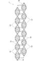
図1は、本発明の実施の形態に係る発泡体層積層体の構成を概略的に示す断面図である。この図1において、発泡体層積層体1の最上面に一方の布帛層1Aが配置され、最下面に他方の布帛層1Bが配置されている。各布帛層1A,1Bは、それぞれ織物により製織されている。発泡体層積層体1は、発泡体層2が一方の布帛層1Aと他方の布帛層1Bとに狭持された3層のサンドイッチ構造を形成する。また、一方の布帛層1Aと他方の布帛層1Bとは、すべての位置で同じ長さの合成繊維のモノフィラメント糸3によって連結されている。このため、一方の布帛層1Aと他方の布帛層1Bとは略平行を保ち、厚さが均一な板状となる。さらに、任意の2本のモノフィラメント糸3は互いに略平行となっている。すなわち、任意の2本のモノフィラメント糸3,3が、一方の布帛層1Aに対しそれぞれ連結される連結点間の距離と、他方の布帛層1Bに対しそれぞれ連結される連結点間の距離とが、ほぼ等しくなっている。よって、発泡体層積層体1は曲率を持たない平板状となる。
FIG. 1 is a cross-sectional view schematically showing a configuration of a foam layer laminate according to an embodiment of the present invention. In FIG. 1, one
また、図2は、発泡体層積層体1の布帛層1A,1B及びモノフィラメント糸3から構成された基材11をたて糸と平行に切断した断面図である。この図2に示すように、一方の布帛層1Aと他方の布帛層1Bとがモノフィラメント糸3で連結された発泡体層積層体1としては、2枚の基布11A,11Bをパイル31で連結した二重パイル織物が適用されている。この2枚の基布11A,11Bは、それぞれたて糸12A,12Bと、よこ糸13A,13Bとで構成されている。この場合、図2において、よこ糸13A,13Bの太さをたて糸12A,12B及びパイル31よりもかなり太く図示しているが、基材11の構成を分かりやすくするために便宜上太さに差をつけているに過ぎず、たて糸12A,12B、よこ糸13A,13B及びパイル31の太さは、図示したほどの差がないものとする。
FIG. 2 is a cross-sectional view of the
パイル31は、上側では基布11Aに織り込まれて当該基布11Aに接合され、下側では基布11Bに織り込まれて当該基布11Bに接合されている。また、パイル31は、一方の基布11Aに織り込まれた後、他方の基布11Bに織り込まれるまでの間で、どちらの基布11A,11Bにも織り込まれない柱状部分を有しており、この柱状部分の長さによって、発泡体層2の厚さが決定される。つまり、パイル31としては、基材11を構成するパイルたて糸が適用されている。なお、図2において、一方の基布11Aが一方の布帛層1Aに、他方の基布11Bが他方の布帛層1Bに、パイル31がモノフィラメント糸3に、それぞれ対応している。また、両基布11A,11B及びパイル糸31によって基材11が構成され、この基材11に発泡体層2となる発泡体20を介在させることで発泡体層積層体1が構成される。
The
一方の布帛層1Aと他方の布帛層1Bとがモノフィラメント糸3で連結された本発明の発泡体層積層体1を構成する二重パイル織物は、例えば、ベルベット織機のナイフスライダ(製織された二重パイル織物のパイルを巻取り前に切断する装置)を取り外して、一方の基布11Aと他方の基布11Bとが、パイル31で連結されたままで巻き取り装置に巻き取らせることで製造できる。なお、基布11A,11Bである織物の組織は、平織、綾織等の三原組織であっても、ドビー組織等の変化組織であってもよい。
A double pile fabric constituting the
ここで、布帛層1A,1B及びモノフィラメント糸3について詳細に説明する。
両布帛層1A,1Bを構成する糸は、紡績糸、マルチフィラメント糸、モノフィラメント糸等の製織に使用できる構造のものであればなんでもよい。また、糸を構成する繊維の種類は、綿、麻等の天然繊維、レーヨン等の再生繊維、ナイロン、ポリエステル等の合成繊維、又は、炭素繊維、ガラス繊維等の無機繊維が用途に応じて用いられる。更に、混紡、合糸等の周知の方法により、異なる種類の繊維を組み合わせて用いることも可能である。要するに、布帛層1A,1Bを構成する糸の構造および繊維種には種々のものを用いることができるが、発泡体層積層体1の強度・剛性をより重視する場合には、アラミド繊維、炭素繊維、ガラス繊維等の高強度で高弾性の繊維が用いられる。また、用途によっては、ポリエステル等の合成繊維のフィラメント糸を用いることが経済的である。
Here, the fabric layers 1A and 1B and the
The yarns constituting both
また、一方の布帛層1Aと他方の布帛層1Bとをそれぞれ構成する糸についても、同種であってもよく、異なる種類であってもよいが、曲率のない平板状の発泡体層積層体1とするためには、同種の糸を用いることが好ましい。一方、積極的に異なる種類の糸を用いて発泡体層積層体1に厚さ方向の曲率を持たせることも可能である。この点については後に詳述する。
Also, the yarn constituting each of the one
そして、モノフィラメント糸3を構成する繊維としては、ナイロン、ポリエステル、ポリエチレン、ポリプロピレン、ポリ塩化ビニル、ポリ塩化ビリニデン、フッ素樹脂、又はポリフェニレンサルファイド等のような合成繊維が用いられる。
As the fibers constituting the
次に、布帛層1A,1Bを構成する糸およびパイル31を構成するモノフィラメント糸3の太さについて説明する。
基布11A,11Bを構成する糸の太さは、たて糸12A,12B、よこ糸13A,13Bとも、特に限定しないが、ポリエステル製のマルチフィラメント糸を用いた場合には、100〜1000dtexであれば製織が容易である。また、糸の材質によっては、適正な範囲が異なるが、製織可能な範囲で適宜選択することができる。
Next, the thickness of the yarn constituting the fabric layers 1A and 1B and the thickness of the
The thicknesses of the yarns constituting the
パイル31の太さは、製織可能な範囲で適宜選択され、ポリエステル製のモノフィラメント糸からなるパイルを用いた場合には、100〜800dtexであれば製織可能である。また、発泡体層積層体の厚さ方向の圧縮強度・圧縮剛性を考慮すると200dtexが好ましく、製織の容易さからは600dtex以下が好ましい。また、糸の材質によっては、適正な範囲が異なるが、製織可能な範囲で適宜選択される。
The thickness of the
図3は、曲げモーメントを受けている従来の発泡体層積層体9及び本発明の発泡体層積層体1の断面をそれぞれ模式的に表したものである。図3の(a)は布帛層91,92及び発泡体層93を接着した従来の発泡体層積層体9、図3の(b)は本発明の発泡体層積層体1の変形状態をそれぞれ表している。図3の(a)に示すように、曲げ変形が生じている発泡体層積層体9には、布帛層91,92に沿って内側では圧縮加重(図中の細矢印)、外側では引張荷重(図中の細矢印)が生じている。これらの布帛層91,92に沿った荷重の合力が発泡体層積層体9の厚さ方向に圧縮荷重(図中の太矢印)を生じさせる。よって、従来の発泡体層積層体9に曲げ変形を加えると、曲げ部で厚さが薄くなり、剛性の低下を来たしていることが分かる。これは、発泡体層93が、空間を薄い壁状又は細い柱状の実部で覆ったセルと呼ばれる構造単位が連なって形成されているために、圧縮荷重に対して壁状又は柱状の実部が低荷重であっても座屈を生じ易いからである。
FIG. 3 schematically shows cross sections of a conventional
これに対し、本発明の発泡体層積層体1では、図3の(b)に示すように、モノフィラメント糸3からなるパイル31の周りに発泡体20が充填されているため、パイル31の座屈に必要な屈曲の自由度が発泡体により阻害され、結果として、圧縮荷重(図中の太矢印)をモノフィラメント糸3の軸方向で負荷できるようになっている。これにより、モノフィラメント糸3は、厚さ方向の圧縮荷重を支える柱として機能し、発泡体20の曲げ部の厚さが薄くなることを妨げ、発泡体層積層体1の剛性が低下することを防ぐ効果を有している。
On the other hand, in the
次に、布帛層の結合にマルチフィラメント糸や紡績糸でなくモノフィラメント糸を用いることによって、布帛層1A,1B同士の間での座屈荷重を高めて発泡体層積層体1の剛性・強度を高めることができる根拠について説明する。
Next, by using monofilament yarn instead of multifilament yarn or spun yarn for bonding the fabric layers, the buckling load between the fabric layers 1A and 1B is increased, and the rigidity and strength of the
座屈荷重Wcは、オイラーの公式によると、 According to Euler's formula, the buckling load Wc is

となり、座屈荷重は、柱の断面二次モーメントIに比例する。ここで、nは端末条件係数、πは円周率、Eはヤング率、lはパイルの長さをそれぞれ表す。
ここで、断面が直径d0の円形である単繊維がm本集まって総断面積がAとなっているフィラメント糸について考える。単繊維の断面二次モーメントI0は、次式で表される。
Thus, the buckling load is proportional to the sectional moment I of the column. Here, n represents a terminal condition coefficient, π represents a circular ratio, E represents a Young's modulus, and l represents a pile length.
Here, let us consider a filament yarn in which m single fibers having a circular cross section of diameter d 0 are gathered and the total cross sectional area is A. The cross-sectional secondary moment I 0 of the single fiber is expressed by the following formula.
一方、フィラメント糸の断面二次モーメントIは、繊維の断面二次モーメントの総和であるため、I=m・I0である。 On the other hand, since the cross-sectional secondary moment I of the filament yarn is the sum of the cross-sectional secondary moments of the fiber, I = m · I 0 .
また、繊維の直径d0と断面積の総和Aとの関係は、
![]()
![]()
よって、同じ断面積(太さ)を持つフィラメント糸であれば、繊維の構成本数mが少ない方が断面二次モーメントが大きくなり、座屈荷重が大きくなる。 Therefore, if the filament yarn has the same cross-sectional area (thickness), the smaller the number m of the fibers, the greater the cross-sectional secondary moment and the greater the buckling load.
要するに、フィラメント1本で糸を構成するモノフィラメント糸を用いると、同じ太さのマルチフィラメントや紡績糸を用いるよりも、発泡体層積層体1の曲げ部での厚さ方向の圧縮変形が小さい。
この結果から、パイル31として、細い繊維を集合させたマルチフィラメント糸や紡績糸を使用するよりもモノフィラメント糸3を使用することで、発泡体層積層体1の剛性・強度を向上させる上で有利であることが分かる。
In short, when a monofilament yarn that forms a yarn with a single filament is used, compressive deformation in the thickness direction at the bent portion of the
From this result, it is advantageous in improving the rigidity and strength of the
次に、両布帛層1A,1Bの間に発泡体層3を形成する発泡体層積層体1の製造方法の一例を図4に基づいて説明する。
Next, an example of the manufacturing method of the foam layer laminated
まず、図4の(a)に示すように、製織工程において、上述したように、一方の布帛層1A及び他方の布帛層1Bを構成する2枚の基布11A,11Bをそれぞれたて糸とよこ糸とで製織し、それぞれの基布11A,11Bをモノフィラメント糸3からなるパイル31で連結した二重パイル織物を適用する。つまり、製織工程では、二重パイル織物を構成する2枚の基布11A,11Bを製織するとともに、パイルたて糸で各布帛層1A,1B同士を適宜間隔に連結して、基材11(二重パイル織物)を製織する。このとき、パイル31は、上側の一方の基布11Aに織り込まれて当該基布11Aに接合されているとともに、下側の他方の基布11Bに織り込まれて当該基布11Bに接合されており、基材11のパイルたて糸がパイル31として用いられている。また、パイル31は、一方の基布11Aに織り込まれた後、他方の基布11Bに織り込まれるまでの間で、どちらの基布11A,11Bにも織り込まれない柱状部分を有している。この柱状部分の長さは、均一としている。この場合、基材11は二重構造布帛であり、その製造方法としては、例えば経緯二重組織を用いた経パイル織物などが挙げられる。
First, as shown in FIG. 4A, in the weaving process, as described above, the two
次いで、図4の(b)に示すように、端縁封止工程として、製織工程において製織された布帛層1A,1Bの端縁を、発泡体原料を挿入ないし注入する注入部15を除いて封止しておく。例えば、両布帛層1A,1Bの端縁を密着させておき、ミシン等を用いて、注入部15を除いて縫い合わせることで布帛層1A,1Bの端縁を封止する。また、熱融着シートによる溶着、接着剤による接着によっても、注入部15を除いた端縁の封止が可能である。これによって、布帛層1A,1Bの端縁からの発泡体原料の漏れ出しを防止している。
Next, as shown in FIG. 4 (b), as the edge sealing step, the edges of the fabric layers 1A and 1B woven in the weaving step are excluded except for the
発泡体20の材質は、既存のものを使用すればよく、布帛層1A,1Bの間に原料を挿入または注入でき、発泡に必要な加熱、または、反応熱による温度上昇に基材11が耐えられるものであればよい。例えば、硬質ポリウレタンフォームは、発泡・硬化時に反応熱が生じるが、ポリエステル等の合成繊維のガラス転移点(Tg)まで温度上昇しないため、ポリエステル等の合成繊維からなる糸で構成した基材11と硬質ポリウレタンフォームによる発泡体層2とを組み合わせることが可能である。
An existing material may be used for the
硬質ポリウレタンフォームは、多くの用途に用いられており、経済性に優れる。また、イソシアネートとポリオールとを混合攪拌することで、容易に発泡・硬化させることが可能である。また、硬質ポリウレタンフォームは、独立気泡の割合が90%程度を占めるため、剛性の高い発泡体層積層体とすることができる。更に、硬質ポリウレタンフォームは、自己接着性を有するため、布帛層1A,1B及び合成繊維のモノフィラメント糸からなるパイルと接着して、さらに強固な発泡体層積層体を得ることができる。 Rigid polyurethane foam is used for many applications and is excellent in economic efficiency. Further, it is possible to easily foam and cure by mixing and stirring the isocyanate and the polyol. Moreover, since the ratio of closed cells occupies about 90%, the rigid polyurethane foam can be a highly rigid foam layer laminate. Furthermore, since the rigid polyurethane foam has self-adhesive properties, it can be bonded to a pile made of monofilament yarns of the fabric layers 1A and 1B and synthetic fibers to obtain a stronger foam layer laminate.
本発明の発泡体層2に硬質ポリウレタンフォームを用いる場合には、イソシアネートとポリオールとを混合攪拌後、混合液の発泡開始前までに、布帛層1A,1Bの端縁の注入部15にノズル41を差し込んで布帛層1A,1B同士の間に注入器4により混合液を注入する。なお、混合液の注入時、織物である布帛層1A,1Bを透過して混合液が漏れる場合があるが、布帛層1A,1Bつまり基布11A,11Bの織物密度を上げるか、ポリウレタンの原料液を粘度の高いものに変更することによって、混合液の漏れが防止される。
When a rigid polyurethane foam is used for the
また、発泡体原料の漏れの防止手段として、基布11A,11Bの一部をフィルム等でシールした混合液停留部を設けていてもよい。すなわち、図4の(b)に示すように、布帛層1A,1Bを鉛直方向に保持し、上部の注入部15より混合液を注入すると、混合液は、重力により布帛層1A,1Bの下部に溜まる。このとき、布帛層1A,1Bの混合液が溜まる混合液停留部をシールしておけば、混合液を漏らすことなく発泡開始まで布帛層1A,1B同士の間に保持される。
Further, as a means for preventing leakage of the foam raw material, a mixed liquid retaining portion in which a part of the
発泡を開始した混合液は、布帛層1A,1Bを発泡圧力により押し広げるように膨張しながら、混合液貯留部から布帛層1A,1B同士の間を上方に向かって流動してゆく。なお、発泡しながら流動する混合液は、発泡前に比べて布帛層1A,1Bを透過し難くなるので、布帛層1A,1B全体にシールを施す必要はない。 The liquid mixture that has started foaming flows upward from the liquid mixture storage part to the space between the fabric layers 1A and 1B while expanding so as to expand the fabric layers 1A and 1B by the foaming pressure. In addition, since the mixed liquid that flows while foaming is less likely to permeate the fabric layers 1A and 1B than before foaming, it is not necessary to seal the entire fabric layers 1A and 1B.
このとき、混合液の注入量が不足すると、布帛層1A,1B全体に発泡体層2を形成できないため、十分な量の混合液を注入する必要がある。例えば、寸法が、長辺x、短辺yの長方形状の基材11であり、その基材11の全体でパイル31の長さが一定値zである場合には、十分な混合液を注入すると、体積がxyzの発泡体層積層体1を形成できる。よって、混合液の発泡倍率をαとすると、xyz/α以上の量の混合液を注入する必要がある。しかし、混合液が膨張する際に、重力に抗して上昇する必要があり、パイル31の隙間を縫って流動する必要があるため、上記計算値より多めに注入することが好ましい。また、発泡倍率αは、温度、湿度等の諸条件で異なることがあるため、注入量は実際の製造条件の下での実験によって求めることが好ましい。
At this time, if the injection amount of the mixed liquid is insufficient, the
また、発泡が布帛層1A,1B上部の注入部15に達する前に、注入部15を塞いでおけば、注入部15からの漏れ出しが防止され、発泡圧で布帛層1A,1B全体のパイル31を伸ばして所望の厚さの発泡体層積層体1が形成される。
Further, if the
なお、布帛層1A,1Bの通気度が10〜30cm3/cm2・s程度であれば、発泡時に空気は容易に布帛層1A,1Bを透過して押し出されるが、発泡中の混合液は透過せずに、布帛層1A,1B同士の間に保持されるため、注入部15を塞いでも、布帛層1A,1B全体が発泡体20で満たされる。ただし、発泡体原料の粘度によって最適な通気度は異なるので、製造に際しては、予め試験によって適度な通気度を確認することが好ましい。
Note that if the air permeability of the fabric layers 1A and 1B is about 10 to 30 cm 3 / cm 2 · s, the air is easily pushed through the fabric layers 1A and 1B during foaming. Since it does not permeate and is held between the fabric layers 1A and 1B, the entire fabric layers 1A and 1B are filled with the
また、注入量が多すぎる場合には、布帛層1A,1Bの内部で発泡圧が高くなり過ぎるため、余分を注入部15から積極的に漏らすか、圧が一定以上になった場合に発泡した液が漏れ出すような微小な孔を布帛層1A,1Bに設けることが好ましい。
Further, when the injection amount is too large, the foaming pressure becomes too high inside the fabric layers 1A and 1B, so that excess is actively leaked from the
そして、図4の(c)に示すように、混合液の発泡・硬化後に、布帛層1A,1Bの端縁を切除し、発泡体層2を貫通して布帛層1A,1B同士をモノフィラメント糸3により連結した3層構造の発泡体層積層体1を得る。
Then, as shown in FIG. 4 (c), after foaming / curing of the mixed solution, the edges of the fabric layers 1A and 1B are cut out, and the fabric layers 1A and 1B pass through the
本発明の発泡体層積層体の発泡体層の材質としては、上記の硬質ポリウレタンフォームの他に、ポリスチレンフォーム、フェノールフォーム、ユリアフォーム、メラニンフォーム、エポキシフォーム等の樹脂フォームを使用できる。 As a material for the foam layer of the foam layer laminate of the present invention, resin foams such as polystyrene foam, phenol foam, urea foam, melanin foam, and epoxy foam can be used in addition to the above-mentioned rigid polyurethane foam.
次に、本発明の発泡体層積層体1をそれぞれ異なる材料及び製法により作製した実験例1、2及び比較例1に基づいて説明する。なお、本発明は、以下の各実験例に限定されるものではない。
Next, the
[実験例1]
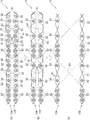
ナイフスライダを取り外したベルベット織機(ヴァンデヴィーレ社製VMM−22)で、基布(布帛層)が2層とも平織りの二重パイル織物を製織した。図5に示すように、基布のたて糸にポリエステル製のマルチフィラメント糸(333dtex、構成本数72本、撚り数259T/m)、よこ糸にポリエステル製のマルチフィラメント糸(999dtex、構成本数216本、撚り数912T/m)、パイルにポリエステル製のモノフィラメント糸(280dtex)を用いた。密度は、基布のたて糸が50本/inch、よこ糸が60本/inch、パイルがたて7本/inchである。また、パイルの長さは17mmであり、基材全体で一様のパイル長とした。
製織した二重パイル織物を、30cm×30cmの正方形に切断し基材とした。
[Experimental Example 1]
With a velvet loom (VMV-22, manufactured by Van De Ville) with the knife slider removed, a double pile fabric having a plain weave in both layers was woven. As shown in FIG. 5, a polyester multifilament yarn (333 dtex, number of components 72, twist 259 T / m) is used as the warp yarn of the base fabric, and a polyester multifilament yarn (999 dtex, number of components 216 is twisted) as the weft. 912 T / m), and monofilament yarn (280 dtex) made of polyester was used for the pile. The density of the warp of the base fabric is 50 / inch, the weft is 60 / inch, and the pile is 7 / inch. The pile length was 17 mm, and the pile length was uniform throughout the substrate.
The woven double pile fabric was cut into a 30 cm × 30 cm square to form a substrate.
このときの基材の通気度は、22cm3/cm2・sであった。なお、基布の通気度は、パイルを切断した1枚の基布について、JIS L1096(2010)の通気性試験法(フラジール形法)に従いテクステクト社製通気度試験機FX−3300(圧力設定125Pa)で測定した値である。 The air permeability of the base material at this time was 22 cm 3 / cm 2 · s. In addition, the air permeability of the base fabric is determined based on the air permeability tester FX-3300 manufactured by Textect (pressure setting 125 Pa) according to the air permeability test method (Fragile method) of JIS L1096 (2010) for one base fabric from which the pile is cut. ).
次いで、基材の端縁を発泡体原料を注入する注入部を除いて両布帛層を重ねてミシンで縫製して端縁の封止を行った。 Next, both the fabric layers were overlapped on the edge of the substrate except for the injection part for injecting the foam material, and the edges were sealed by sewing with a sewing machine.
その後、注入部を上にして、布帛層が鉛直になるように基材を保持し、硬質ウレタンフォームの原料液を注入部から注入した。原料はポリオール(シールドエアー社製インスタパックリジッド200ポリウレタンレジン)と、イソシアネート(シールドエアー社製インスタパックリジッド200クルードMDI)をほぼ1:1の割合で液温62°Cにて混合攪拌したものである。注入量は全体で約80gである。 Then, the base was held so that the fabric layer was vertical with the injection part facing upward, and the raw material liquid of rigid urethane foam was injected from the injection part. The raw material is a mixture of polyol (Instapack Rigid 200 polyurethane resin manufactured by Shield Air) and isocyanate (Instapack Rigid 200 Crude MDI manufactured by Shield Air) at a liquid temperature of 62 ° C in a ratio of approximately 1: 1. is there. The total injection amount is about 80 g.
原料液は基材の底部に溜まり、約10秒間発泡せずに布帛層から漏れることなく留まっていた。ポリオールの粘度は77mPa・s、イソシアネートの粘度は33mPa・sであった。なお、粘度は東京計器製E型回転粘度計(設定温度62°C、回転数100rpm)で測定した値である。 The raw material liquid was collected at the bottom of the base material and remained without leaking from the fabric layer without foaming for about 10 seconds. The viscosity of the polyol was 77 mPa · s, and the viscosity of the isocyanate was 33 mPa · s. The viscosity is a value measured with an E-type rotational viscometer (set temperature: 62 ° C., rotation speed: 100 rpm) manufactured by Tokyo Keiki.
発泡を開始した原料液は、両布帛層の間を膨張しながら流動して基材の上部に達した。その際、膨張・流動する原料液は両基布を透過して漏れることはなかった。
また、基材の注入部をクリップで塞いでいたため、発泡により生じる膨張圧力で、基布同士の間のパイルが緊張状態となり、一定厚さを有する板状となった。このとき、基布同士の間にあった空気は布帛層を通して容易に排出され、基布同士の間に硬質ウレタンフォームが充填された。
The raw material liquid that started foaming flowed while expanding between both fabric layers and reached the upper part of the base material. At that time, the expanding and flowing raw material liquid did not leak through the base fabric.
Moreover, since the injection | pouring part of the base material was block | closed with the clip, the pile between base fabrics became a tension | tensile_strength by the expansion pressure which arises by foaming, and it became a plate shape which has fixed thickness. At this time, the air between the base fabrics was easily discharged through the fabric layer, and the rigid urethane foam was filled between the base fabrics.
発泡体20の硬化後、発泡体層積層体の端縁を切断して、厚さが20mmで均一な、25cm角の平板状の発泡体層積層体を得た。
After the
[実験例2]
実験例1と同一の織機で、図6の(a)に示すように、たて糸方向の断面が図のとおりである二重パイル織物を製織した。図7に示すように、51は基材11の基布11A,11Bのたて糸(ポリエステル製のマルチフィラメント糸333dtex、構成本数72本、撚り数259T/m)、52は基布11A,11Bのよこ糸(ポリエステル製のマルチフィラメント糸999dtex、構成本数216本、撚り数912T/m)、53は基布11A,11Bのよこ糸(水溶性ビニロン製の紡績糸193dtex)、54はパイル(ポリエステル製のモノフィラメント糸(220dtex))である。密度は、基布11A,11Bのたて糸51が50本/inch、よこ糸52,53が60本/inch、パイル54がたて7本/inch、よこ14本/inchである。パイル54の長さは、17mmであり、基材11全体で一様のパイル長とした。
[Experiment 2]
With the same loom as in Experimental Example 1, as shown in FIG. 6 (a), a double pile fabric having a cross section in the warp direction as shown in the figure was woven. As shown in FIG. 7, 51 is the warp yarn of the
図6の(b)に示すように、製織したパイル織物を70°Cの熱湯中でかき混ぜて基布11A,11Bのよこ糸53を溶解させて、たて糸方向の断面が図のとおりである基材11とした。つまり、図6の(c)に示すように、水溶性のよこ糸53を溶かすことによって、製織したパイル織物の約3倍のパイル長を有する基材11を作成した。基材11のパイル54の長さは50mmとなった。乾燥させた基布11A,11Bの通気度は23cm3/cm2・sであった。
As shown in FIG. 6B, the weave pile fabric is agitated in hot water at 70 ° C. to dissolve the
次に、実験例1と同様に注入部を除いて端縁の封止を行い、原料液停留部の漏れ防止を施した。 Next, in the same manner as in Experimental Example 1, the edges were sealed except for the injection part, and leakage of the raw material liquid retention part was prevented.
注入量が約120gであること以外は、実験例1と同様に硬質ウレタンフォームの原料液を注入し、厚さが50mmで25cm角の平板状の発泡体層積層体を得た。このとき、布帛層の通気度は、実験例1より若干大きいが、発泡後、膨張・流動する原料液が布帛層から漏れることはなかった。 Except that the injection amount was about 120 g, the raw material liquid of rigid urethane foam was injected in the same manner as in Experimental Example 1, and a flat foam layer laminate having a thickness of 50 mm and a 25 cm square was obtained. At this time, the air permeability of the fabric layer was slightly larger than that of Experimental Example 1, but the raw material liquid that expanded and fluidized after foaming did not leak from the fabric layer.
[比較例1]
実験例2と同様の発泡ポリウレタン原料を用いて、一辺が25cmの正方形で、厚さが50mmの硬質ポリウレタンフォームの成型品を作製した。また、図8に示すように、実験例2で使用したものと同一の基材のパイルを切断して、パイルのない2枚の基布を作製した。これらの基布が成型品の両面に接着されるように成型前に型内に仮止めし、基布同士の間に発泡ウレタンを充填させることで、基布同士がパイルにより連結されない従来例と同様の発泡体層積層体を作製した。
[Comparative Example 1]
Using the same foamed polyurethane raw material as in Experimental Example 2, a molded product of a rigid polyurethane foam having a square with a side of 25 cm and a thickness of 50 mm was produced. Moreover, as shown in FIG. 8, the pile of the same base material as what was used in Experimental example 2 was cut | disconnected, and two base fabrics without a pile were produced. Prior to molding, these base fabrics are temporarily fixed in the mold so as to be bonded to both surfaces of the molded product, and by filling the foamed urethane between the base fabrics, the base fabrics are not connected by a pile. A similar foam layer laminate was prepared.
実験例2及び比較例1の発泡体層積層体の厚み方向の圧縮試験を次の方法により行った。すなわち、発泡体層積層体の布帛層と直角に交わりたて糸と平行な2面と、同様に布帛層と直角に交わりよこ糸と平行な2面に沿って発泡体層積層体を切断して、50mm×50mmの正方形の平面と、元の発泡体層積層体の厚さ(50mm)を有するブロック状の試料を作製した。JIS K7220(2006)に準ずる方法で、厚さ方向の圧縮試験を行い、荷重−変位曲線を得た。試験には、インストロン5569型万能材料試験機を用いた。なお、圧縮速度(試験機クロスヘッドの移動速度)を5mm/分とした。得られた荷重−変位曲線を図9に示す。 A compression test in the thickness direction of the foam layer laminates of Experimental Example 2 and Comparative Example 1 was performed by the following method. That is, the foam layer laminate is cut along two surfaces parallel to the warp yarn intersecting at right angles to the fabric layer of the foam layer laminate, and similarly to two surfaces intersecting perpendicularly to the fabric layer and parallel to the weft yarn. A block-like sample having a square plane of 50 mm and the thickness (50 mm) of the original foam layer laminate was produced. A compression test in the thickness direction was performed by a method according to JIS K7220 (2006) to obtain a load-displacement curve. Instron 5569 type universal material testing machine was used for the test. The compression speed (moving speed of the test machine crosshead) was 5 mm / min. The obtained load-displacement curve is shown in FIG.
この荷重−変位曲線の初期の傾きは、実験例2では、比較例1に比べて大きい。よって、合成繊維のモノフィラメント糸からなるパイルが柱となって荷重を支えていることが分かる。
また、降伏点荷重(発泡体のセルを構成する柱状又は壁状の実部、及び、パイルが座屈し始める荷重)に達すると、変位が増加しても、圧縮荷重は上昇せずに微小な上下動を呈するようになるが、このときの荷重も実験例2では、比較例1に比べて大きい。よって、モノフィラメント糸からなるパイルが圧縮強度を向上させていることが分かる。
The initial slope of the load-displacement curve is larger in Experimental Example 2 than in Comparative Example 1. Therefore, it can be seen that a pile made of a synthetic filament monofilament serves as a pillar and supports the load.
In addition, when the yield point load (the columnar or wall-shaped real part constituting the foam cell and the load at which the pile begins to buckle) is reached, even if the displacement increases, the compressive load does not increase and becomes minute. Although vertical movement is exhibited, the load at this time is also larger in Experimental Example 2 than in Comparative Example 1. Therefore, it can be seen that the pile made of monofilament yarn improves the compressive strength.
次に、実験例2及び比較例1の発泡体層積層体の曲げ試験を次の方法により行った。 Next, the bending test of the foam layer laminates of Experimental Example 2 and Comparative Example 1 was performed by the following method.
先ず、基材のよこ糸方向が長手方向となる長さ220mm、幅50mm、厚さ50mmの試験片を作製し、JIS K7221−1及び2(2006)に準ずる方法で、厚さ方向の三点曲げ試験を行った。このとき、支点間距離を180mmとした。また、試験には、インストロン5569型万能材料試験機を用いた。更に、支点での発泡体層の局所的な陥没を極力抑えるようにするため、加圧くさびと支点とをそれぞれ半径15mmの円柱状とした。なお、曲げ速度(試験機クロスヘッドの移動速度)を20mm/分とした。 First, a test piece having a length of 220 mm, a width of 50 mm, and a thickness of 50 mm, in which the weft direction of the base material is the longitudinal direction, is prepared, and three-point bending in the thickness direction is performed in accordance with JIS K7221-1 and 2 (2006). A test was conducted. At this time, the distance between fulcrums was 180 mm. For the test, an Instron 5569 universal material testing machine was used. Furthermore, in order to suppress local depression of the foam layer at the fulcrum as much as possible, the pressure wedge and the fulcrum were each formed in a columnar shape with a radius of 15 mm. The bending speed (moving speed of the test machine cross head) was 20 mm / min.
得られた荷重−変位曲線を図10に示す。この荷重−変位曲線の初期の傾きは、実験例2では、比較例1に比べて大きい。よって、実験例1では、モノフィラメント糸からなるパイルが柱となって厚さ方向に生じる圧縮荷重を支えることから、厚さが薄くならない結果、曲げ剛性が向上することが分かる。 The obtained load-displacement curve is shown in FIG. The initial slope of the load-displacement curve is larger in Experimental Example 2 than in Comparative Example 1. Therefore, in Experimental Example 1, it can be seen that the bending rigidity is improved as a result of the thickness not being reduced because the pile made of monofilament yarn becomes a column and supports the compressive load generated in the thickness direction.
また、比較例1では、曲げ変形が大きくなると、上面(曲げの内側)で布帛層が一部剥離したが、実験例2では、布帛層の剥離は生じなかった。 In Comparative Example 1, when the bending deformation increased, the fabric layer partially peeled on the upper surface (inside the bend), but in Experimental Example 2, the fabric layer did not peel.
ここで、実験例2及び比較例1の発泡体層積層体の見かけ密度について説明する。 Here, the apparent density of the foam layer laminated body of Experimental example 2 and Comparative example 1 is demonstrated.
実験例2及び比較例1の発泡体層積層体の見かけ密度をJIS K7222(2005)に準ずる方法で求めた。なお、重量と体積の測定に用いた試験片は、圧縮試験に用いたものと同様に作製した。 The apparent density of the foam layer laminates of Experimental Example 2 and Comparative Example 1 was determined by a method according to JIS K7222 (2005). In addition, the test piece used for the measurement of weight and volume was produced similarly to what was used for the compression test.
実験例2の発泡体層積層体の見かけ密度は、59.1kg/m3であった。また、比較例1の発泡体層積層体の見かけ密度は、61.9kg/m3であった。 The apparent density of the foam layer laminate of Experimental Example 2 was 59.1 kg / m 3 . The apparent density of the foam layer laminate of Comparative Example 1 was 61.9 kg / m 3 .
この結果から、実験例2の方が、見かけ密度が低いことから発泡倍率が若干大きいものと考えられる。一般的に、発泡倍率が大きければ、強度・剛性は小さくなると考えられる。従って、実験例2の方が、比較例1よりも強度・剛性が高い結果となったのは、発泡倍率の違いではないことが証明された。 From this result, it is considered that Experimental Example 2 has a slightly higher expansion ratio because of its lower apparent density. Generally, if the expansion ratio is large, the strength and rigidity are considered to be small. Therefore, it was proved that it was not the difference in the expansion ratio that the experimental example 2 resulted in higher strength and rigidity than the comparative example 1.
したがって、上記実施の形態では、合成繊維のモノフィラメント糸3によって発泡体層2を貫通して各布帛層1A,1B同士の間が適宜間隔に連結されているので、発泡体層積層体1の厚さ方向の圧縮強度及び圧縮剛性が向上している。このため、発泡体層積層体に曲げ変形やねじり変形を加えても、厚さが薄くなることを防止でき、優れた強度・剛性を得ることができる。また、発泡体層積層体1に曲げ変形やねじり変形が生じても、布帛層1A,1Bの座屈による浮き上がりや、布帛層1A,1Bと発泡体層2との境界での剥離が確実に防止される。これにより、曲げ変形やねじり変形に対して発泡体層積層体1の十分な強度・剛性を得ることができる。
Therefore, in the above embodiment, the
また、各布帛層1A,1Bが二重パイル織物を構成する2枚の基布11A,11Bにより形成されているとともに、その基材11のパイルたて糸がパイル31(モノフィラメント糸3)として適用されているので、モノフィラメント糸3を別途設けて各布帛層1A,1B同士の間を連結する必要がなく、モノフィラメント糸3による各布帛層1A,1B同士の連結を簡単に行うことができる。しかも、パイルたて糸(パイル31)で連結された2枚の基布11A,11Bの間に発泡体原料を挿入または注入すれば、容易に発泡体層2が得られ、発泡体層積層体1を簡単に製造することができる。
Each
また、発泡体層2の原料として液状の硬質発泡樹脂が適用されているので、液状の硬質発泡樹脂を布帛層1A,1Bの間に注入して安易に発泡体層2を得ることができる。しかも、硬質発泡樹脂によって発泡体層2の強度・剛性の向上も図られ、耐久性及び制振性に優れた発泡体層積層体1を提供することができる。
Moreover, since the liquid hard foam resin is applied as a raw material of the
また、各布帛層1A,1Bとしてガラス繊維を含んだ強化布帛層が適用されていれば、各布帛層1A,1Bの強度・剛性がより一層高められ、全体としての発泡体層積層体1の強度・剛性機能をさらに向上させることができる。
Moreover, if the reinforcement | strengthening fabric layer containing glass fiber is applied as each
更に、織物である2層の布帛層1A,1Bと、この布帛層1A,1B同士の間を適宜間隔に連結する合繊繊維のモノフィラメント糸3からなるパイル31を有する二重パイル織物(基材)を製織する製織工程と、モノフィラメント糸3によって連結した各布帛層1A,1B同士の端縁を発泡体原料の注入部15を除いて封止する端部封止工程と、各布帛層1A,1B同士の間に注入部15より発泡体を充填して発泡硬化後に発泡体層2を得る発泡体充填工程とにより発泡体層積層体1が製造されているので、厚さ方向の圧縮強度及び圧縮剛性が向上しかつ曲げ変形やねじり変形に対して十分な強度・剛性が得られた発泡体層積層体1を提供することができる。しかも、合成繊維のモノフィラメント糸3からなるパイル31で連結された各布帛層1A,1B同士の間に発泡体原料を注入して容易に発泡体層2が得られ、発泡体層積層体1を簡単に製造することができる。
Furthermore, the double pile fabric (base material) which has the
なお、本発明は上記実施の形態に限定されるものではなく、その他種々の変形例を包含している。例えば、上記実施の形態では、各布帛層を二重パイル織物(基材)を構成する2枚の基布により形成し、その基材のパイルたて糸をモノフィラメント糸として用いたが、各基布の間に板状に形成された発泡体を介在させた状態で、発泡体を貫通させて各布帛層同士を合成繊維のモノフィラメント糸により連結することで、発泡体層積層体が製造されるようにしてもよい。具体的には、織物からなる各基布同士の間に予め形成された発泡体層を介在させる発泡体層介在工程と、この発泡体層介在工程により介在された発泡体層を合成繊維のモノフィラメント糸により貫通して各布帛層同士の間を適宜間隔に連結する布帛層連結工程とを具備する。この場合においても、厚さ方向の圧縮強度及び圧縮剛性が向上しかつ曲げ変形やねじり変形に対して十分な強度・剛性が得られた発泡体層積層体を提供することが可能となる In addition, this invention is not limited to the said embodiment, Other various modifications are included. For example, in the above embodiment, each fabric layer is formed by two base fabrics constituting a double pile fabric (base material), and the pile warp yarn of the base material is used as a monofilament yarn. The foam layer laminate is manufactured by interposing the foam and connecting the fabric layers with the monofilament yarn of the synthetic fiber with the foam formed in a plate shape interposed therebetween. May be. Specifically, a foam layer intervening step in which a foam layer formed in advance is interposed between each base fabric made of woven fabric, and the foam layer interposed by the foam layer interposing step is a monofilament of synthetic fiber A fabric layer connecting step of penetrating through the yarn and connecting between the fabric layers at appropriate intervals. Even in this case, it is possible to provide a foam layer laminate having improved compressive strength and compressive rigidity in the thickness direction and sufficient strength and rigidity against bending deformation and torsional deformation.
また、上記実施の形態では、2枚の布帛層1A,1Bと発泡体層2とで三層構造の発泡体層積層体1を構成したが、各布帛層の少なくとも一方の布帛層の反発泡体層側に、その一方の布帛層と対面するように新たな布帛層を設けるとともに、この互いに対面する布帛層同士の間に新たな発泡体層を設け、その新たな発泡体層を貫通して上記互いに対面する布帛層同士の間を適宜間隔に連結する合成繊維のモノフィラメント糸からなる新たなパイルを備えていてもよい。この場合には、各布帛層の少なくとも一方の布帛層とこれに対面する新たな布帛層との間にも発泡体層を設けた分厚い発泡体層積層体が得られ、曲げ変形やねじり変形に対してより一層十分な強度・剛性を得ることが可能となる。
Moreover, in the said embodiment, although the two
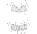
また、上記実施の形態では、任意の2つのモノフィラメント糸3,3同士を布帛層1A,1Bに対し直交させて互いに略平行としたが、図11に示すように、全てのモノフィラメント糸32,33が布帛層1A,1Bに対し直交していなくてもよい。つまり、一方のモノフィラメント糸32と他方のモノフィラメント糸33とを布帛層1A,1Bに対し傾斜させて、基材である二重パイル織物において隣り合うパイルとして製織されていてもよい。このモノフィラメント糸32,33は、布帛層1A,1Bのよこ糸方向に順に繰り返し配置されている。この場合、モノフィラメント糸32,33は、布帛層1A,1Bに対して傾斜しているものの、モノフィラメント糸32,33同士が同一角度で反対側に傾斜しているため、力のバランスが取れており、平板状の発泡体層積層体14を形成することが可能となる。
In the above embodiment, any two
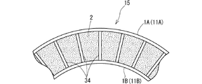
また、上記実施の形態では、任意の2本のモノフィラメント糸3を互いに略平行としたが、図12に示すように、任意の2つのモノフィラメント糸34,34同士の間隔を両布帛層1A,1Bとの連結部で異ならせることで、モノフィラメント糸34,34同士が互いに平行にならず、放射状になっていてもよい。すなわち、一方の基布11A(図12では上側の基布)と他方の基布11B(図12では下側の基布)とで互いに熱収縮率の異なる糸をそれぞれのよこ糸として用い、製織後に加熱すると、熱収縮率が高いよこ糸が大きく収縮するため、加工前は同じ長さであった基布11A,11Bによこ糸方向での長さの不均衡が生じる。よって、熱収縮率の高いよこ糸を用いた他方の基布11Bと共にフィラメント糸34,34同士の間隔が狭くなり、このように処理した基材11に発泡体層2を形成すると、熱収縮率の高いよこ糸を用いた他方の基布11Bが内側となるような曲率を持った発泡体層積層体15が形成されていてもよい。
In the above embodiment, any two
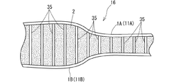
また、上記実施の形態では、一方の基布11Aと他方の基布11Bとをすべての位置において同じ長さのパイル糸31によって連結したが、図13に示すように、パイル糸35の長さを基布11A,11Bのたて糸方向で変更し、そのたて糸方向で厚さの異なる部分を有する発泡体層積層体16が形成されていてもよい。この場合、厚さの異なる部分同士の間は、たて糸方向で段階的に長さを異ならせたモノフィラメント糸35によって布帛層同士1A,1Bが連結され、段差が生じないようにしている。
Moreover, in the said embodiment, although one
また、上記実施の形態では、布帛層1A,1Bを織物により構成したが、布帛層の表面に樹脂層を設けていてもよい。例えば、発泡体が発泡・硬化した後に、エポキシ樹脂を塗布して硬化させることで、布帛層の表面に樹脂層を形成すればよい。この場合には、曲げ変形した際に内側となった布帛層の座屈を防ぐことができ、発泡体層積層体の強度・剛性をさらに高めることが可能となる。
Moreover, in the said embodiment, although
また、予め布帛層に樹脂を含浸させて複合材料とした基材に発泡体層を形成することによっても、同様の効果が得られる。 Further, the same effect can be obtained by forming a foam layer on a base material made into a composite material by impregnating a fabric layer with a resin in advance.
また、熱反射シートや化粧板などのような他の機能を持つ材料を積層すれば、本発明の機能に加えて他の機能を併せ持つ発泡体層積層体とすることが可能となる。 Moreover, if materials having other functions such as a heat reflecting sheet and a decorative board are laminated, a foam layer laminate having other functions in addition to the functions of the present invention can be obtained.
また、本発明の発泡体層積層体を構成する合成繊維のモノフィラメント糸からなるパイルは、それぞれが、1本のモノフィラメントであっても、2本のモノフィラメントを引き揃えた無撚りの糸から構成されていてもよい。このとき、3本以上のモノフィラメントを用いると、製織の困難性から1本当たりのモノフィラメントの太さを小さくせざるを得ないため、モノフィラメント糸からなるパイルの座屈荷重が小さくなり、発泡体層積層体の剛性を確保することが困難となる。また、複数のモノフィラメントを引き揃えた糸に撚りを加えると、モノフィラメントの直線性がなくなるため、座屈荷重が低下する。これに対し、2本のモノフィラメントを引き揃えた無撚りの糸からなるパイルとした場合は、モノフィラメント1本当たりの太さが十分に太くても(例えば200〜500dtex)、製織の困難性は伴わず、無撚りであるために座屈荷重の低下も生じない。 In addition, the pile made of the synthetic filament monofilament yarn constituting the foam layer laminate of the present invention is composed of untwisted yarn in which two monofilaments are aligned even if each is a single monofilament. It may be. At this time, if three or more monofilaments are used, the thickness of the monofilament per filament has to be reduced due to difficulty in weaving, so the buckling load of the pile made of monofilament yarns is reduced, and the foam layer It becomes difficult to ensure the rigidity of the laminate. Further, when twisting is applied to a yarn in which a plurality of monofilaments are arranged, the linearity of the monofilament is lost, and the buckling load is reduced. On the other hand, in the case of a pile made of untwisted yarn in which two monofilaments are aligned, even if the thickness per monofilament is sufficiently large (for example, 200 to 500 dtex), there is a difficulty in weaving. In addition, the buckling load does not decrease because of no twisting.
更に、発泡体層積層体を構造材、断熱材又は遮音材に使用すれば、厚さ方向の圧縮強度及び圧縮剛性を向上させかつ曲げ変形やねじり変形に対して十分な強度・剛性を得た発泡体層積層体によって、強度・剛性の高い構造材、断熱材又は遮音材を提供することが可能となる。 Furthermore, if the foam layer laminate is used as a structural material, a heat insulating material or a sound insulating material, the compressive strength and compressive rigidity in the thickness direction are improved, and sufficient strength and rigidity against bending deformation and torsional deformation are obtained. With the foam layer laminate, it is possible to provide a structural material, a heat insulating material, or a sound insulating material with high strength and rigidity.
1 発泡体層積層体
1A,1B 布帛層
11 基材
11A,11B 基布
15 注入部
2 発泡体層
20 発泡体
3 モノフィラメント糸
DESCRIPTION OF
Claims (8)
上記発泡体層を貫通して上記各布帛層同士の間を適宜間隔に連結する合成繊維のモノフィラメント糸からなるパイルを備えていることを特徴とする発泡体層積層体。 A foam layer laminate comprising two fabric layers made of woven fabric and a foam layer provided between these fabric layers,
A foam layer laminate comprising a pile of monofilament yarns of synthetic fibers that penetrate through the foam layer and connect the fabric layers to each other at appropriate intervals.
上記新たな発泡体層を貫通して上記互いに対面する布帛層同士の間を適宜間隔に連結する合成繊維のモノフィラメント糸からなる新たなパイルを備えている請求項1〜請求項3のいずれか1つに記載の発泡体層積層体。 On the anti-foam layer side of at least one of the fabric layers, a new fabric layer is provided so as to face the one fabric layer, and between the fabric layers facing each other. Has a new foam layer,
A new pile of monofilament yarns of synthetic fibers that penetrate the new foam layer and connect the fabric layers facing each other at appropriate intervals is provided. 2. The foam layer laminate according to 1.
上記各布帛層同士の間に上記発泡体層を介在させる発泡体層介在工程と、
上記発泡体層介在工程により介在された発泡体層を合成繊維のモノフィラメント糸により貫通して上記各布帛層同士の間を適宜間隔に連結する布帛層連結工程と、
を有していることを特徴とする発泡体層積層体の製造方法。 A method for producing a foam layer laminate comprising two fabric layers made of woven fabric and a foam layer provided between the fabric layers,
A foam layer interposing step of interposing the foam layer between the fabric layers;
A fabric layer connecting step of penetrating the foam layer interposed by the foam layer interposing step with a monofilament yarn of synthetic fiber and connecting the fabric layers at appropriate intervals;
A method for producing a foam layer laminate, comprising:
上記各布帛層を製織する際に、上記各布帛層を二重パイル織物を構成する2枚の基布により形成するとともに、その二重パイル織物を構成するパイルたて糸を、上記各布帛層同士を適宜間隔に連結する合成繊維のモノフィラメント糸からなるパイルとして用いて、二重パイル織物を製織する製織工程と、
上記パイルによって連結した上記各布帛層同士の端縁を発泡体原料の注入部を除いて封止する端部封止工程と、
上記各布帛層同士の間に上記発泡体層が得られるように上記注入部より発泡体を充填する発泡体充填工程と、
を有していることを特徴とする発泡体層積層体の製造方法。 A method for producing a foam layer laminate comprising two fabric layers made of woven fabric and a foam layer provided between the fabric layers,
When weaving the fabric layers, the fabric layers are formed by two base fabrics constituting the double pile fabric, and the pile warp yarns constituting the double pile fabric are bonded to the fabric layers. Weaving process for weaving a double pile fabric, using as a pile of monofilament yarns of synthetic fibers connected at appropriate intervals;
An end sealing step for sealing the edges of the fabric layers connected by the pile, excluding the injection portion of the foam raw material,
A foam filling step of filling the foam from the injection portion so that the foam layer is obtained between the fabric layers;
A method for producing a foam layer laminate, comprising:
Priority Applications (1)
| Application Number | Priority Date | Filing Date | Title |
|---|---|---|---|
| JP2011018297A JP2012158039A (en) | 2011-01-31 | 2011-01-31 | Foam layer laminated body and method for manufacturing the same, as well as structural material, heat insulating material or sound insulator using the foam layer laminated body |
Applications Claiming Priority (1)
| Application Number | Priority Date | Filing Date | Title |
|---|---|---|---|
| JP2011018297A JP2012158039A (en) | 2011-01-31 | 2011-01-31 | Foam layer laminated body and method for manufacturing the same, as well as structural material, heat insulating material or sound insulator using the foam layer laminated body |
Publications (1)
| Publication Number | Publication Date |
|---|---|
| JP2012158039A true JP2012158039A (en) | 2012-08-23 |
Family
ID=46838984
Family Applications (1)
| Application Number | Title | Priority Date | Filing Date |
|---|---|---|---|
| JP2011018297A Pending JP2012158039A (en) | 2011-01-31 | 2011-01-31 | Foam layer laminated body and method for manufacturing the same, as well as structural material, heat insulating material or sound insulator using the foam layer laminated body |
Country Status (1)
| Country | Link |
|---|---|
| JP (1) | JP2012158039A (en) |
Cited By (5)
| Publication number | Priority date | Publication date | Assignee | Title |
|---|---|---|---|---|
| WO2014051062A1 (en) * | 2012-09-27 | 2014-04-03 | 大日本印刷株式会社 | Foam-laminated sheet |
| JP2014069571A (en) * | 2013-09-03 | 2014-04-21 | Dainippon Printing Co Ltd | Foamed and laminated sheet |
| JP2017502177A (en) * | 2013-12-13 | 2017-01-19 | スリーエム イノベイティブ プロパティズ カンパニー | Articles containing microcapsules for on-demand bonding and method for producing the same |
| CN107557950A (en) * | 2017-09-12 | 2018-01-09 | 苏州赛力菲陶纤有限公司 | A kind of hollow fabric of variable thickness |
| CN111770817A (en) * | 2018-02-28 | 2020-10-13 | 索尼公司 | Sound-proof device, robot apparatus, control method for robot apparatus, and program |
-
2011
- 2011-01-31 JP JP2011018297A patent/JP2012158039A/en active Pending
Cited By (9)
| Publication number | Priority date | Publication date | Assignee | Title |
|---|---|---|---|---|
| WO2014051062A1 (en) * | 2012-09-27 | 2014-04-03 | 大日本印刷株式会社 | Foam-laminated sheet |
| RU2648083C2 (en) * | 2012-09-27 | 2018-03-22 | Дай Ниппон Принтинг Ко., Лтд. | Foamed multi-layer sheet |
| JP2014069571A (en) * | 2013-09-03 | 2014-04-21 | Dainippon Printing Co Ltd | Foamed and laminated sheet |
| JP2017502177A (en) * | 2013-12-13 | 2017-01-19 | スリーエム イノベイティブ プロパティズ カンパニー | Articles containing microcapsules for on-demand bonding and method for producing the same |
| US11306431B2 (en) | 2013-12-13 | 2022-04-19 | 3M Innovative Properties Company | Articles including microcapsules for on-demand adhesion and methods of making same |
| CN107557950A (en) * | 2017-09-12 | 2018-01-09 | 苏州赛力菲陶纤有限公司 | A kind of hollow fabric of variable thickness |
| CN111770817A (en) * | 2018-02-28 | 2020-10-13 | 索尼公司 | Sound-proof device, robot apparatus, control method for robot apparatus, and program |
| EP3760397A4 (en) * | 2018-02-28 | 2021-08-11 | Sony Group Corporation | Soundproofing device, robot device, robot device control method and program |
| CN111770817B (en) * | 2018-02-28 | 2023-11-14 | 索尼公司 | Sound-proof device, robot device, control method for robot device, and program |
Similar Documents
| Publication | Publication Date | Title |
|---|---|---|
| US11318716B2 (en) | Composite construction for an increased service life | |
| JP2012158039A (en) | Foam layer laminated body and method for manufacturing the same, as well as structural material, heat insulating material or sound insulator using the foam layer laminated body | |
| JP5588645B2 (en) | Jig for manufacturing a composite material structure having a thick portion in a cross section | |
| US6995099B1 (en) | Composite reinforcing fiber base material, preform and production method for fiber reinforced plastic | |
| US4753837A (en) | Novel laminated panel | |
| ES2635375T3 (en) | Stabilized preform precursors and stabilized preforms for composite materials and processes to stabilize and compact preforms | |
| US5262230A (en) | Lightweight composite material with a thermoset matrix | |
| Hassanzadeh et al. | Thermoset composites reinforced by innovative 3D spacer weft-knitted fabrics with different cross-section profiles: Materials and manufacturing process | |
| RU2617484C2 (en) | Unidirectional reinforcing filler and method for producing unidirectional reinforcing filler | |
| US10106925B2 (en) | Nonwoven flexible composites | |
| RU2616667C2 (en) | Crosslinked one-way or multi-axis reinforcing filler and method for its production | |
| WO2005095079A1 (en) | Preform, frp, and processes for producing these | |
| US10683592B2 (en) | Hybrid woven textile for composite reinforcement | |
| JP2006515809A (en) | Three-dimensional knitted spacer woven sandwich composite | |
| KR101583849B1 (en) | Woven structure and panel or vessel including such structure | |
| US3996084A (en) | Lock core panel | |
| Hassanzadeh et al. | Mechanical characterization of innovative 3D multi-cell thermoset composites produced with weft-knitted spacer fabrics | |
| US3960236A (en) | Lock core panel | |
| JP4984973B2 (en) | Manufacturing method of fiber reinforced resin | |
| JP3776384B2 (en) | Repair and reinforcement methods for concrete structures | |
| JP2007125745A (en) | Glass fiber reinforced plastic material, glass fiber reinforced plastic prepreg, glass fiber reinforced plastic layer and lng tank | |
| WO2017151866A1 (en) | Nonwoven flexible composites | |
| JPH11107107A (en) | Carbon fiber woven fabric and fiber-reinforced plastic and molding of fiber-reinforced plastic | |
| WO2013025115A1 (en) | Three- dimensional (3d) knitted reinforced composite structure production method thereof | |
| JP2001082676A (en) | Base material for formation of inner surface of conduit |