JP4984973B2 - Manufacturing method of fiber reinforced resin - Google Patents
Manufacturing method of fiber reinforced resin Download PDFInfo
- Publication number
- JP4984973B2 JP4984973B2 JP2007052321A JP2007052321A JP4984973B2 JP 4984973 B2 JP4984973 B2 JP 4984973B2 JP 2007052321 A JP2007052321 A JP 2007052321A JP 2007052321 A JP2007052321 A JP 2007052321A JP 4984973 B2 JP4984973 B2 JP 4984973B2
- Authority
- JP
- Japan
- Prior art keywords
- resin
- fiber
- substrate
- base material
- diffusion medium
- Prior art date
- Legal status (The legal status is an assumption and is not a legal conclusion. Google has not performed a legal analysis and makes no representation as to the accuracy of the status listed.)
- Active
Links
Images


Description
本発明は、繊維強化樹脂(以下、FRP(Fiber Reinforced Plastic)と称することもある。)の製造方法に関し、とくに、RTM成形法(Resin Transfer Molding)による繊維強化樹脂の製造方法に関する。 The present invention relates to a method for producing a fiber reinforced resin (hereinafter sometimes referred to as FRP (Fiber Reinforced Plastic)), and more particularly, to a method for producing a fiber reinforced resin by an RTM molding method (Resin Transfer Molding).
なお、本発明におけるRTM成形法には、上下対となる両面成形型を使用し、樹脂注入口から樹脂排出口へ向けて樹脂を加圧注入し、樹脂による型内の空気押し出し後に樹脂排出口を閉じ型内を樹脂を加圧して硬化させるRTM成形法、型内を真空状態にした後、樹脂を吸引あるいは加圧注入し、硬化させるRTM成形法、および、片面成形型に基材を配置し、フィルムなどのバッグ材でバギングして内部を減圧した後、内部の真空圧によって樹脂を吸引注入する真空RTM成形法が含まれる。 In the RTM molding method of the present invention, a double-sided mold that is a pair of upper and lower sides is used, and resin is injected under pressure from the resin injection port toward the resin discharge port. RTM molding method that closes the mold and pressurizes the resin to cure, RTM molding method that cures the resin by suction or pressure injection after the mold is evacuated, and the substrate is placed on the single-sided mold In addition, a vacuum RTM molding method is included in which after bagging with a bag material such as a film to decompress the inside, the resin is sucked and injected by the internal vacuum pressure.
FRPは軽量、かつ、高い機械的性質を有する複合材料として極めて広い分野で活用されている。このようなFRPの成形方法の一つとして、RTM成形法が広く用いられている。RTM成形法においては、成形サイクルタイムは比較的短いが、樹脂流れの不具合などにより成形品表面にピンホールやボイドと呼ばれる欠陥が残ることがあり、外観の良さを必要とする商品に適用しようとする場合には、塗装工程の前に表面補修工程等が必要であった。このようなことから、RTM成形法により製造されたFRPは、外観の仕上げに手間と労力がかかり、高コストの製品となりがちであった。 FRP is used in a very wide field as a composite material having a light weight and high mechanical properties. As one of such FRP molding methods, the RTM molding method is widely used. In the RTM molding method, the molding cycle time is relatively short, but defects such as pinholes and voids may remain on the surface of the molded product due to defects in resin flow, etc., so that it is intended to be applied to products that require good appearance. When doing so, a surface repair process etc. were required before the painting process. For these reasons, FRP manufactured by the RTM molding method is labor-intensive and labor-intensive to finish the appearance, and tends to be a high-cost product.
そこで、このような従来のRTM成形法の問題点を解決するための検討が種々なされてきた。例えば特許文献1では、RTM成形に使用する成形型内に表層形成部材/ろ過抵抗の大きい分離基材/繊維状補強材/ろ過抵抗の小さい分離基材/発泡性樹脂粒子からなる積層物を型内に入れ、成形型温度を上げ発泡性粒子の体積膨張によって表層基材を成形型に押し付け、そこへ液状成形樹脂を注入し、高表面品質複合材料成形品を得る成形方法が提案されている。しかしながらこの方法では、ろ過抵抗の大きい分離基材で発泡性粒子が表層へ流出しない構成とすることが必須であり、積層構成が制限されること、発泡性粒子の発泡温度まで加熱して成形後、当該粒子の発泡内圧による成形品変形を防ぐため液状樹脂硬化後、十分に成形型温度を下げなければならないため、設備の増大、成形サイクルタイムが長くなるといった問題があった。 Therefore, various studies have been made to solve the problems of the conventional RTM molding method. For example, in Patent Document 1, a laminate composed of a surface layer forming member / a separation base material having a high filtration resistance / a fibrous reinforcing material / a separation base material having a low filtration resistance / expandable resin particles in a mold used for RTM molding is molded. A molding method has been proposed in which the molding layer temperature is raised, the surface layer base material is pressed against the molding die by the volume expansion of the expandable particles, and a liquid molding resin is injected into the molding die to obtain a molded article with a high surface quality composite material. . However, in this method, it is essential to have a structure in which the foamable particles do not flow out to the surface layer with a separation substrate having a high filtration resistance, the layered structure is limited, and after the molding by heating to the foaming temperature of the foamable particles In order to prevent deformation of the molded product due to the foaming internal pressure of the particles, the temperature of the mold must be sufficiently lowered after the liquid resin is cured, resulting in problems such as an increase in equipment and a long molding cycle time.
また、特許文献2には、積層において表層となる強化繊維機材の真下にランダムマット層を設けることで、強化繊維基材中の気泡を抜き、かつ表層の強化繊維基材への樹脂の含浸を促進する成形方法が提案されている。しかしながらこの方法では、表層基材の真下にランダムマット層を配置することから、樹脂中に含まれる気泡がランダムマット層に溜まり、直上の表層基材に貫通するピンホールを生じることがあった。
本発明の目的は、従来のRTM成形法において表層に発生していたピンホール等の表面欠陥を減少させ、後工程の塗装工程等に必要な補修工程を低減させることで成形品の生産性を向上させることにある。 The purpose of the present invention is to reduce the surface defects such as pinholes that have occurred on the surface layer in the conventional RTM molding method, and to reduce the repair process required for the subsequent painting process, etc., thereby improving the productivity of the molded product. It is to improve.
上記課題を解決するために種々の検討を行った結果、特定のカバーファクターを有する中間層と特定の含浸性を有する樹脂拡散層を設けることで、成形品表面にピンホール発生がほとんどなく表面品位に優れたRTM成形品が得られることが分かり、本発明が完成された。 As a result of various investigations to solve the above-mentioned problems, by providing an intermediate layer having a specific cover factor and a resin diffusion layer having a specific impregnation property, there is almost no pinholes on the surface of the molded product, and surface quality is improved. It was found that an excellent RTM molded product can be obtained, and the present invention has been completed.
すなわち、本発明に係る繊維強化樹脂の製造方法は、一対の型のキャビティ内に少なくとも強化繊維基材を配置し、前記キャビティ内に樹脂を注入し硬化させる繊維強化樹脂の製造方法であって、前記強化繊維基材の少なくとも片面に、少なくとも一方の型内表面に直接接触させる表層形成用基材と、該表層形成用基材と前記強化繊維基材との間に位置し前記表層形成用基材との含浸係数比率が1.5〜10であるメッシュからなる樹脂拡散媒体とを、カバーファクターが90%〜100%である少なくとも1枚の織物からなる中間層を介して配置するとともに、前記樹脂拡散媒体の前記強化繊維基材と面する側の少なくとも一部にコア材を配置し、該コア材の少なくとも樹脂注入側の端部に、含浸係数が1×10 −10 m 2 以上であり厚み50〜2000μmの樹脂流動基材を設けることを特徴とする方法からなる。 That is, the method for producing a fiber reinforced resin according to the present invention is a method for producing a fiber reinforced resin in which at least a reinforced fiber base is disposed in a pair of mold cavities, and the resin is injected into the cavity and cured. At least one surface of the reinforcing fiber base material, a surface layer forming base material that is in direct contact with at least one inner surface of the mold, and the surface layer forming base material positioned between the surface layer forming base material and the reinforcing fiber base material A resin diffusion medium comprising a mesh having an impregnation coefficient ratio of 1.5 to 10 with a material is disposed via an intermediate layer comprising at least one woven fabric having a cover factor of 90% to 100%, and A core material is disposed on at least a part of the resin diffusion medium facing the reinforcing fiber substrate, and an impregnation coefficient is 1 × 10 −10 m 2 or more at least on an end portion on the resin injection side of the core material . Thickness Consists method characterized by providing a resin flow substrate 50 to 2000 m.
このような本発明におけるRTM成形法においては、積層構成内に特定の中間層および樹脂拡散媒体を配置することで、樹脂注入に伴い混入する気泡を、まず樹脂流動性の良い樹脂拡散媒体内を主として樹脂と共に流動させることにより、良好に排出させたり当該樹脂拡散媒体層内に滞在させたりすることができ、更に、所定範囲のカバーファクターを有する中間層を最外層と樹脂拡散媒体の間に設けることで、樹脂拡散媒体内に滞在する気泡が成形品表面へ露出することを防ぐことができるようになる。一方樹脂は、樹脂拡散媒体内に包含させ、かつ樹脂拡散媒体から表層側基材へと気泡の少ない樹脂を供給して含浸を進めることができるので、従来のRTM成形法では困難であった意匠表面のボイドやピンホール等の欠陥が発生することが極めて少ない成形品を効率よく短時間で安定的に成形できる。 In such an RTM molding method in the present invention, by disposing a specific intermediate layer and a resin diffusion medium in the laminated structure, bubbles mixed with the resin injection are first introduced in the resin diffusion medium having good resin fluidity. By mainly flowing together with the resin, it can be discharged well or stay in the resin diffusion medium layer, and an intermediate layer having a predetermined range of cover factor is provided between the outermost layer and the resin diffusion medium. This makes it possible to prevent the bubbles staying in the resin diffusion medium from being exposed to the surface of the molded product. On the other hand, since the resin can be included in the resin diffusion medium and the resin can be impregnated by supplying resin with less bubbles from the resin diffusion medium to the surface layer side base material, a design that has been difficult with the conventional RTM molding method A molded product in which defects such as surface voids and pinholes are extremely small can be efficiently and stably molded in a short time.
上記本発明に係る繊維強化樹脂の製造方法においては、樹脂拡散媒体の少なくとも一端部が、少なくとも一方の隣接層よりも外側に向けて延長されている形態を採用することが可能である。樹脂拡散媒体の少なくとも一端部を、少なくとも一方の隣接層よりも長くすることにより、その長く形成された端部から注入樹脂が樹脂拡散媒体内に進入、展開されやすくなり、樹脂が確実に樹脂拡散媒体の層内に供給されるようになる。その結果、積層体の内部まで確実に樹脂が行き渡るようになって、積層体全体に対する樹脂含浸性が大幅に向上される。 In the method for producing a fiber reinforced resin according to the present invention, it is possible to adopt a form in which at least one end portion of the resin diffusion medium is extended outward from at least one adjacent layer. By making at least one end of the resin diffusion medium longer than at least one adjacent layer, it becomes easy for the injected resin to enter and expand into the resin diffusion medium from the long end, and the resin diffuses reliably. To be fed into the layer of media. As a result, the resin reliably reaches the inside of the laminate, and the resin impregnation property for the entire laminate is greatly improved.
この樹脂拡散媒体の含浸係数は1×10⁻¹⁰m2以上であることが好ましい。含浸係数は、樹脂の含浸のし易さを表す係数であるが、その測定方法については後述する。含浸係数が高い樹脂拡散媒体を用いることにより、所望の範囲への樹脂の展開が容易化されるとともに、展開された樹脂の含浸性も向上され、かつ、上記の端部を長く形成したことによる作用効果が一層良好に発現される。 The impregnation coefficient of the resin diffusion medium is preferably 1 × 10 −10 m 2 or more. The impregnation coefficient is a coefficient representing the ease of impregnation of the resin, and the measurement method will be described later. By using a resin diffusion medium having a high impregnation coefficient, the resin can be easily developed to a desired range, the impregnation property of the developed resin is improved, and the end portion is formed long. The effect is expressed even better.
また、樹脂拡散媒体の厚みとしては、200〜2000μmの範囲にあることが好ましい。樹脂拡散媒体には上述の如く含浸係数の高いことが好ましいことから、このような含浸係数の高い基材を用いることにより、十分な量の樹脂を樹脂拡散媒体の端部から中央部あるいは反対側の端部に向けて流動させることが可能になる。しかしこの樹脂拡散媒体が薄すぎると、十分な量の樹脂を流動させることが難しくなり、反対に厚すぎると、積層体全体として、所望の積層形態の維持が難しくなる。したがって、厚みは200〜2000μmの範囲内とすることが好ましい。 The thickness of the resin diffusion medium is preferably in the range of 200 to 2000 μm. Since it is preferable that the resin diffusion medium has a high impregnation coefficient as described above, by using a base material having such a high impregnation coefficient, a sufficient amount of resin can be transferred from the end of the resin diffusion medium to the center or the opposite side. It becomes possible to make it flow toward the end of the. However, if the resin diffusion medium is too thin, it becomes difficult to flow a sufficient amount of resin, and if it is too thick, it becomes difficult to maintain a desired laminated form as a whole laminate. Therefore, the thickness is preferably in the range of 200 to 2000 μm.
また、本発明に係る繊維強化樹脂の製造方法においては、樹脂拡散媒体の強化繊維基材と面する側の少なくとも一部にコア材を配置し、該コア材の少なくとも樹脂注入側の端部に、含浸係数が1×10 −10 m 2 以上であり厚み50〜2000μmの樹脂流動基材を設ける形態を採用することができる。この樹脂流動基材はコア材の端部のみに配置すればよく、コア材の全面にわたっている必要はない。また、樹脂流動方向に少なくとも一方の端部に配置されていればよいが、望ましくは両端部に配置される。このようにコア材の端部に、特定の樹脂流動基材の層が配置されることで、コア材端部での樹脂流動が極めて安定し、従来この部位から成形体の表面へと至りやすかった気泡が、成形体内部に細かく分散されて封じ込められ、表面に露出しにくくなる。その結果、成形体の表面品位が大幅に向上されることになる。 Further, in the method for producing a fiber reinforced resin according to the present invention, a core material is disposed on at least a part of the resin diffusion medium facing the reinforcing fiber base , and at least an end of the core material on the resin injection side. Further, it is possible to adopt a form in which a resin fluidized substrate having an impregnation coefficient of 1 × 10 −10 m 2 or more and a thickness of 50 to 2000 μm is provided. This resin fluid base material should just be arrange | positioned only at the edge part of a core material, and does not need to cover the whole surface of a core material. Moreover, although it should just be arrange | positioned at at least one edge part in the resin flow direction, it arrange | positions desirably at both ends. As described above, the specific resin flow base material layer is arranged at the end of the core material, so that the resin flow at the end of the core material is extremely stable, and it has been easy to reach the surface of the molded body from this part conventionally. The air bubbles are finely dispersed inside the molded body and contained, and are not easily exposed on the surface. As a result, the surface quality of the molded body is greatly improved.
この樹脂流動基材としては、その含浸係数が1×10⁻¹⁰m2以上であることが必要である。つまり、含浸係数の高い樹脂流動基材とすることで、上記樹脂流動の安定化、気泡の分散、封じ込め効果がより向上される。 The resin fluid base material needs to have an impregnation coefficient of 1 × 10 −10 m 2 or more. That is, by using a resin fluidized base material having a high impregnation coefficient, the resin flow stabilization, the bubble dispersion, and the containment effect are further improved.
また、上記コア材の少なくとも片面に溝加工が施されていることも好ましい。コア溝の存在により、樹脂拡散媒体による拡散樹脂がより迅速にかつ均一に拡散されるようになるので、上記コア材端部に配置された樹脂流動基材による作用と併せて、局部的に気泡が滞留したり成長したりすることが回避され、より均一な成形が可能となる。 It is also preferable that at least one surface of the core material is grooved. Due to the presence of the core groove, the diffusion resin by the resin diffusion medium is diffused more quickly and uniformly, and in combination with the action by the resin flow base disposed at the end of the core material, bubbles are locally generated. Is prevented from staying or growing, and more uniform molding becomes possible.
このように、本発明に係る繊維強化樹脂の製造方法によれば、積層構成内に特定の中間層および樹脂拡散媒体を配置することで、樹脂拡散媒体層内に滞在する気泡が成形品表面へ露出することを効果的に防ぐことができ、表面にボイドやピンホール等の欠陥が発生することが極めて少ない成形品を効率よく短時間で安定的に成形できるようになる。この結果、後工程として塗装工程があるような製造工程でも、表面補修の工程を省略もしくは大幅に軽減でき、低コストの成形品を得ることができる。 As described above, according to the method for producing a fiber reinforced resin according to the present invention, by arranging the specific intermediate layer and the resin diffusion medium in the laminated structure, the bubbles staying in the resin diffusion medium layer are transferred to the surface of the molded product. The exposure can be effectively prevented, and a molded product in which defects such as voids and pinholes are hardly generated on the surface can be molded efficiently and stably in a short time. As a result, even in a manufacturing process in which there is a painting process as a subsequent process, the surface repair process can be omitted or greatly reduced, and a low-cost molded product can be obtained.
以下に、本発明について、望ましい実施の形態とともに詳細に説明する。 Hereinafter, the present invention will be described in detail together with preferred embodiments.
図1は、本発明に係る繊維強化樹脂の製造方法の基本形態の一例を示している。上型2a、下型2bからなる型2のキャビティ1内に、強化繊維基材3が配置され、本実施態様では、強化繊維基材3の両面側に、表層形成用基材4a、4bと、該表層形成用基材4a、4bと強化繊維基材3との間に位置し表層形成用基材4a、4bとの含浸係数比率が1.5〜10である樹脂拡散媒体5a、5bとが、カバーファクターが90%〜100%である織物からなる中間層6a、6bを介して配置される。この状態で、キャビティ1内が例えば矢印7で示すように真空吸引により減圧され、減圧されたキャビティ1内に、矢印8で示すように樹脂注入が行われ、注入された樹脂が、キャビティ1内の基材に含浸された後、例えば加熱により硬化され、所定の繊維強化樹脂の成形体が製造される。
FIG. 1 shows an example of a basic form of a method for producing a fiber reinforced resin according to the present invention. In the cavity 1 of the mold 2 composed of the
本発明で使用する樹脂としては、例えば、エポキシ樹脂やビニルエステル樹脂,不飽和ポリエステル樹脂,フェノール樹脂等の熱硬化性樹脂や、アクリル樹脂やポリアミド樹脂、ポリオレフィン樹脂等が挙げられる。特に常温での粘度が10Pa・s以下であるような粘度が低く繊維への含浸の良好な樹脂が好適である。 Examples of the resin used in the present invention include thermosetting resins such as epoxy resins, vinyl ester resins, unsaturated polyester resins, and phenol resins, acrylic resins, polyamide resins, and polyolefin resins. In particular, a resin having a low viscosity such that the viscosity at room temperature is 10 Pa · s or less and a good impregnation of fibers is preferable.
本発明における強化繊維基材とは、後述する表層形成用基材,中間層用基材,樹脂拡散媒体用基材以外の強化繊維からなる基材の総称である。本発明における強化繊維基材に用いられる強化繊維としては、例えば炭素繊維やガラス繊維,アラミド繊維,PBO(ポリパラフェニレンベンゾビスオキサゾール)繊維,チラノ(チタンアルミナ)繊維,ナイロン繊維などが挙げられる。また、織り組織としては、織布でも不織布でもよく、織布の場合、平織りや綾織り,朱子織り等が挙げられ、単一の繊維で構成するだけでなく複数の繊維を織った組織となってもよい。不織布の場合は、例えば、ランダムマットやコンティニアスストランドマット等が挙げられる。 The reinforcing fiber base in the present invention is a general term for bases made of reinforcing fibers other than the surface layer forming base, intermediate layer base, and resin diffusion medium base to be described later. Examples of the reinforcing fiber used for the reinforcing fiber substrate in the present invention include carbon fiber, glass fiber, aramid fiber, PBO (polyparaphenylene benzobisoxazole) fiber, tyrano (titanium alumina) fiber, and nylon fiber. In addition, the woven structure may be woven or non-woven, and in the case of woven cloth, plain weave, twill weave, satin weave, etc. are mentioned, and it is not only composed of a single fiber but also woven with a plurality of fibers. May be. In the case of a nonwoven fabric, for example, a random mat or a continuous strand mat can be used.
本発明における表層形成用基材とは、成形品の最表層に配置する基材のことであり、後述の樹脂拡散媒体との含浸係数比率を満足する基材である。本発明における表層形成用基材に用いられる繊維としては、例えば炭素繊維やガラス繊維,アラミド繊維,PBO(ポリパラフェニレンベンゾビスオキサゾール)繊維,チラノ(チタンアルミナ)繊維,ナイロン繊維などが挙げられる。また、織り組織としては、織布でも不織布でもよく、織布の場合、平織りや綾織り,朱子織り等が挙げられ、単一の繊維で構成するだけでなく複数の繊維を織った組織となってもよい。不織布の場合は、例えば、ランダムマットが挙げられる。 The surface layer forming base material in the present invention is a base material that is disposed on the outermost layer of the molded product, and is a base material that satisfies an impregnation coefficient ratio with a resin diffusion medium described later. Examples of the fiber used for the surface layer forming substrate in the present invention include carbon fiber, glass fiber, aramid fiber, PBO (polyparaphenylene benzobisoxazole) fiber, tyrano (titanium alumina) fiber, and nylon fiber. In addition, the woven structure may be woven or non-woven, and in the case of woven cloth, plain weave, twill weave, satin weave, etc. are mentioned, and it is not only composed of a single fiber but also woven with a plurality of fibers. May be. In the case of a nonwoven fabric, a random mat is mentioned, for example.
本発明における樹脂拡散媒体とは、樹脂拡散媒体層内の樹脂が流動しやすいように、その他の基材よりも含浸係数が高い層のことであり。後述の表層形成用基材との含浸係数比率を満足する基材である。 The resin diffusion medium in the present invention is a layer having a higher impregnation coefficient than other base materials so that the resin in the resin diffusion medium layer can easily flow. It is a base material that satisfies an impregnation coefficient ratio with a surface layer forming base material to be described later.
この樹脂拡散媒体の形成には、メッシュや繊維基材を用いることができる。メッシュの材質としては、例えば、ナイロン樹脂,ポリプロピレン樹脂,ポリエチレン樹脂等が挙げられ、必要に応じてプラズマ処理やコロナ処理を施して接着性を高めたものを用いてもよい。繊維基材を用いる場合には、用いられる繊維としては、例えば炭素繊維やガラス繊維,アラミド繊維,PBO(ポリパラフェニレンベンゾビスオキサゾール)繊維,チラノ(チタンアルミナ)繊維,ナイロン繊維などが挙げられる。また、織り組織としては、織布でも不織布でもよく、織布の場合、平織りや綾織り,朱子織り等が挙げられ、単一の繊維で構成するだけでなく複数の繊維を織った組織となってもよい。不織布の場合は、例えば、ランダムマットやコンティニアスストランドマット等が挙げられる。 For forming the resin diffusion medium, a mesh or a fiber base material can be used. Examples of the material of the mesh include nylon resin, polypropylene resin, polyethylene resin, and the like, and a material that has been subjected to plasma treatment or corona treatment to improve adhesion as necessary may be used. In the case of using a fiber base material, examples of the fiber used include carbon fiber, glass fiber, aramid fiber, PBO (polyparaphenylene benzobisoxazole) fiber, tyrano (titanium alumina) fiber, and nylon fiber. In addition, the woven structure may be woven or non-woven, and in the case of woven cloth, plain weave, twill weave, satin weave, etc. are mentioned, and it is not only composed of a single fiber but also woven with a plurality of fibers. May be. In the case of a nonwoven fabric, for example, a random mat or a continuous strand mat can be used.
本発明における中間層は、樹脂拡散媒体内を流動する樹脂内の気泡が外層に達しないようにカバーファクターが90%〜100%と高い織物基材である。 The intermediate layer in the present invention is a textile base material having a high cover factor of 90% to 100% so that bubbles in the resin flowing in the resin diffusion medium do not reach the outer layer.
この中間層の織物基材に用いられる繊維としては、例えば炭素繊維やガラス繊維,アラミド繊維,PBO(ポリパラフェニレンベンゾビスオキサゾール)繊維,チラノ(チタンアルミナ)繊維,ナイロン繊維などが挙げられる。また基材の組織としては、織布がよく、平織りや綾織り,朱子織り等が挙げられ、単一の繊維で構成するだけでなく複数の繊維を織った組織となってもよい。 Examples of fibers used for the fabric base material of the intermediate layer include carbon fibers, glass fibers, aramid fibers, PBO (polyparaphenylene benzobisoxazole) fibers, tyrano (titanium alumina) fibers, and nylon fibers. The base material structure is preferably a woven fabric, and includes plain weave, twill weave, satin weave, and the like, and may be composed of not only a single fiber but also a plurality of fibers.
本発明において、表層形成用基材と樹脂流動媒体は、含浸係数の異なる基材層から構成されており、下記の式に示す含浸係数比率が1.5〜10であることが、成形後の表面にピンホールと称する直径で0.2mm以上2mm以下,深さで0.2mm以上1mm以下の穴状等の欠陥が少ない外観を得る為には必要である。この含浸係数比率が1.5よりも低い場合は、樹脂流動差が実質的に生じず、気泡を含んだ樹脂が表層形成用基材側にも流動し、外観表面にピンホールを形成しやすくなる。また、含浸係数比率が10を超える場合は、外観表面のピンホールは少ない反面、樹脂の含浸量が増えることから、成形品の重量増を招く場合がある。 In the present invention, the surface layer forming base material and the resin flow medium are composed of base material layers having different impregnation coefficients, and the impregnation coefficient ratio shown in the following formula is 1.5 to 10 after molding. It is necessary to obtain an appearance with few defects such as a hole shape having a diameter of 0.2 mm to 2 mm and a depth of 0.2 mm to 1 mm on the surface. When this impregnation coefficient ratio is lower than 1.5, there is substantially no difference in resin flow, and the resin containing air bubbles also flows to the surface layer forming substrate side, and it is easy to form pinholes on the external surface. Become. On the other hand, when the impregnation coefficient ratio is more than 10, there are few pinholes on the appearance surface, but the amount of resin impregnation increases, which may increase the weight of the molded product.
含浸係数比率= K1/K2
ここで、
K1:積層された構成の内、基材の含浸係数の最も大きな値(樹脂拡散媒体層の含浸係数)
K2:積層された構成の内、基材の含浸係数の最も小さな値
ここで樹脂含浸係数とは、以下の測定法により測定された値のことである。
Impregnation coefficient ratio = K1 / K2
here,
K1: The largest value of the impregnation coefficient of the base material among the laminated structures (impregnation coefficient of the resin diffusion medium layer)
K2: The smallest value of the impregnation coefficient of the base material among the laminated configurations. Here, the resin impregnation coefficient is a value measured by the following measuring method.
樹脂の含浸過程において、基材に含浸する樹脂の挙動は下式に示すダルシー則に従うことが知られており、含浸速度は以下の式で得られる。 In the resin impregnation process, it is known that the behavior of the resin impregnated into the base material follows the Darcy law shown in the following equation, and the impregnation rate is obtained by the following equation.
v=(K/μ)×(ΔP/ΔL)・・・(1)
ここで、v(m/s)は含浸速度、K(m2)は含浸係数、μは樹脂粘度(Pa・s)、ΔP(Pa)/ΔL(m)は単位長さ当たりの圧力勾配である。この式を時間t(s)で積分すれば、含浸係数は以下の式で得ることができる。
v = (K / μ) × (ΔP / ΔL) (1)
Here, v (m / s) is the impregnation rate, K (m 2 ) is the impregnation coefficient, μ is the resin viscosity (Pa · s), ΔP (Pa) / ΔL (m) is the pressure gradient per unit length. is there. If this equation is integrated over time t (s), the impregnation coefficient can be obtained by the following equation.
K=(L×L×μ)/(2×P×t)・・・(2)
ここで、L(m)は樹脂注入口からフローフロント(流動樹脂の先端)までの距離である。(2)式から、樹脂注入口からフローフロントまでの距離とそこへの到達時間、樹脂粘度、成形圧力が分かれば、含浸係数が計算できる。よって含浸係数の測定は、一例として図2に示すような装置を用いて平板のような基本形状に対して含浸係数測定実験を行い、これらを測定することで含浸係数Kが測定できる。
K = (L × L × μ) / (2 × P × t) (2)
Here, L (m) is the distance from the resin inlet to the flow front (the tip of the fluid resin). If the distance from the resin inlet to the flow front, the arrival time there, the resin viscosity, and the molding pressure are known from the equation (2), the impregnation coefficient can be calculated. Therefore, the impregnation coefficient can be measured by conducting an impregnation coefficient measurement experiment on a basic shape such as a flat plate using an apparatus as shown in FIG. 2 as an example, and measuring these to measure the impregnation coefficient K.
本発明では含浸係数を測定する場合は、例えば、図2に示すような含浸係数測定装置11を用いる。この装置11内をゲージ圧で−100kPaよりも真空度の高い圧力を保持することで、圧力ΔPを100kPaとする。また測定においては、実際の樹脂を用いて、成形温度中で測定することが好ましいが、予め成形温度下での樹脂粘度が分かっていれば、その粘度に調整した液体、例えばシリコンオイルやエーテル系合成油等を用いて測定することもできる。なお、樹脂中入口からフローフロントまでの距離Lは、本発明では、500mmとし、この時の樹脂の到達した時間tを1/100secまで測定可能なディジタル式のストップウオッチで計測する。更にこれら測定は、計3回行った平均値を用いて、含浸係数を算出する。図2において、12は樹脂タンク、13は真空ポンプ、14は基材、15は注入口、16は排出口を、矢印17は樹脂含浸方向を、それぞれ示している。
In the present invention, when measuring the impregnation coefficient, for example, an impregnation
本発明における中間層に用いられる織物基材としては、カバーファクターが90%〜100%の基材を用いる。中間層に90%以上のカバーファクターの高い基材を1層以上配置することで、樹脂流動媒体から表層形成用基材へ気泡が流出し難くなり、外観にピンホールの少ない成形体が得られる。 As a textile base material used for the intermediate layer in the present invention, a base material having a cover factor of 90% to 100% is used. By disposing one or more base materials having a high cover factor of 90% or more in the intermediate layer, it is difficult for air bubbles to flow out from the resin flow medium to the surface layer forming base material, and a molded body with few pinholes in appearance can be obtained. .
ここでカバーファクターとは、単位面積あたりに占める繊維面積の割合のことを示し、基材が織布の場合、以下の手順で測定される。対象となる基材をコピー機等で拡大し、繊維束10本当たりの縦寸法Yと横寸法Xを測定する。この時のコピー機での拡大は、繊維束10本当たりの横寸法が100±5mmになるように行い、0.01mmまで表示可能なノギスを用いて測定を行う。次にその10本の各繊維束の幅を縦繊維に対しては、X/2のピッチで各繊維束3点の計30点を、横方向の繊維に対しては、Y/2のピッチで各繊維3点の計30点を測定し、縦方向繊維幅平均値xと横方向繊維幅平均値yを算出する。カバーファクターCfは以下の式で表される。 Here, the cover factor indicates the ratio of the fiber area per unit area, and is measured by the following procedure when the base material is a woven fabric. The target substrate is enlarged by a copying machine or the like, and the vertical dimension Y and the horizontal dimension X per 10 fiber bundles are measured. The enlargement with the copying machine at this time is performed so that the lateral dimension per 10 fiber bundles is 100 ± 5 mm, and measurement is performed using calipers capable of displaying up to 0.01 mm. Next, the width of each of the ten fiber bundles is 30 pitches with a pitch of X / 2 for each longitudinal fiber and a total of 30 points for each fiber bundle, and a pitch of Y / 2 for lateral fibers. Then, a total of 30 points of three fibers are measured, and the longitudinal fiber width average value x and the transverse fiber width average value y are calculated. The cover factor Cf is expressed by the following formula.
Cf={Y*x+(X−x)*y}/(X*Y)
本発明において用いられる樹脂拡散媒体の厚みとしては、200〜2000μmであることが、良好な外観性の成形体を得ることから好ましい。200μmよりも薄いと樹脂内部の気泡の通過を妨げて、樹脂注入口付近にボイド溜まりを形成し易くなり、また2000μmよりも厚いと層内に蓄積できるボイドが多くなる反面、成形体としての重量が増加し軽量化の効果が無くなる。なお、かかる厚みの樹脂拡散媒体を得るためには、例えばガラス繊維マットを用いる場合であれば、200〜900g/m2(複数枚でこの目付としても良い)のものを使用することで実現できる。なお、樹脂拡散媒体は、成形体の中に1層のみで構成していても、複数層で構成していても、上記厚みを満足していればよい。
Cf = {Y * x + (X−x) * y} / (X * Y)
The thickness of the resin diffusion medium used in the present invention is preferably 200 to 2000 μm because a molded article having good appearance can be obtained. If it is thinner than 200 μm, the passage of bubbles inside the resin is hindered, and it becomes easy to form a void pool near the resin injection port. If it is thicker than 2000 μm, more voids can be accumulated in the layer, but the weight as a molded body. Increases and the effect of weight reduction is lost. In addition, in order to obtain the resin diffusion medium having such a thickness, for example, when a glass fiber mat is used, it can be realized by using a 200 to 900 g / m 2 (a plurality of sheets may have this basis weight). . In addition, the resin diffusion medium should just satisfy the said thickness, even if it comprises only one layer in a molded object, or it comprises multiple layers.
また、樹脂拡散媒体層に用いられる基材の含浸係数を1×10⁻¹⁰m2以上、例えば1×10⁻¹⁰〜1×10⁻⁹m2とすることで、樹脂が主に樹脂拡散媒体層中に流れるようになり、外観に悪影響を及ぼす樹脂中の気泡等を本樹脂拡散媒体層内に滞在させやすくなることから、良好な外観を持つ成形体を得ることが可能になる。かかる観点より、上限は係数が大きければ大きい方が好ましいが、現状入手可能なものとして上記のような範囲が挙げられる。さらに、含浸係数がさらに大きいものが入手可能となった場合には、好ましく適用することが可能である。 Moreover, the resin is mainly a resin diffusion medium by setting the impregnation coefficient of the base material used for the resin diffusion medium layer to 1 × 10 −10 m 2 or more, for example, 1 × 10 −10 to 1 × 10 −9 m 2. Since the bubbles in the resin that flow into the layer and adversely affect the appearance are easily stayed in the resin diffusion medium layer, it is possible to obtain a molded article having a good appearance. From this point of view, the upper limit is preferably as long as the coefficient is large, but the above-mentioned ranges are listed as currently available. Furthermore, when a thing with a larger impregnation coefficient becomes available, it can apply preferably.
更に、樹脂拡散媒体に用いる材料の形態としては、前述の如く、メッシュでも、織布でも、不織布でも構わないが、例えばガラス繊維チョップドマットや連続ストランドマットといった不織布を用いると、低コストの成形体とすることもでき、また、層内にボイドを蓄えやすくなる。 Further, as described above, the material used for the resin diffusion medium may be a mesh, a woven fabric, or a non-woven fabric. However, if a non-woven fabric such as a glass fiber chopped mat or a continuous strand mat is used, a low-cost molded product is used. Moreover, it becomes easy to accumulate a void in a layer.
また、本発明においては、樹脂拡散媒体の少なくとも一端部が、少なくとも一方の隣接層よりも外側に向けて延長されている形態を採用してもよい。樹脂拡散媒体は両端で延長されていてもよく、各端部の延長形態や隣接層との関係が異なる形態の組み合わせであってもよい、例えば図3に示すように、樹脂拡散媒体21の一方の端部は両隣接層22a、22bよりも飛び出しており、他方の端部は隣接層22bに対してのみ飛び出している形態とすることもできる。L1、L2は樹脂拡散媒体21の飛び出し長さを示しており、少なくとも一方の隣接層より外側に向けて延長されていればよい。このはみ出し長さは1mm以上が望ましく、好ましくは、1mm〜30mmの範囲である。このように樹脂拡散媒体の少なくとも一端部を、少なくとも一方の隣接層よりも長くすることにより、その長く形成された端部から注入樹脂が樹脂拡散媒体内に進入、展開されやすくなり、樹脂がより確実に樹脂拡散媒体の層内に供給されるようになる。
In the present invention, a form in which at least one end of the resin diffusion medium extends outward from at least one adjacent layer may be adopted. The resin diffusion medium may be extended at both ends, or may be a combination of an extended form at each end or a form having a different relationship with the adjacent layer. For example, as shown in FIG. It is also possible to adopt a form in which the end portion of the first protrusion protrudes from both
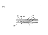
また、樹脂拡散媒体の強化繊維基材と面する側の少なくとも一部にコア材が配置される場合、このコア材の端部部位から成形体の表面へと気泡が至りやすくなるおそれがある。そこで、本発明においては、例えば図4に示すように、コア材31の少なくとも樹脂注入側の端部において(図示例では両端部において)、樹脂拡散媒体32との間に、含浸係数が1×10 −10 m 2 以上であり厚み50〜2000μmの樹脂流動基材33を設けることが必要である。この樹脂流動基材33はコア材31の端部のみに配置すればよく、コア材31の全面にわたっている必要はない。このような特定の樹脂流動基材33がコア材31の端部に配置されることで、コア材31の端部での樹脂流動が極めて安定し、この部位から成形体の表面へと至りやすかった気泡が、成形体内部に細かく分散されて封じ込められ、表面に露出しにくくなる。その結果、成形体の表面品位が大幅に向上されることになる。なお、図4において、34は中間層、35は表層形成用基材を、それぞれ示している。
Moreover, when a core material is arrange | positioned in at least one part of the side which faces the reinforced fiber base material of a resin diffusion medium, there exists a possibility that a bubble may reach easily from the edge part site | part of this core material to the surface of a molded object. Therefore, in the present invention, for example, as shown in FIG. 4, the impregnation coefficient is 1 × between the
上記樹脂流動基材33としては、前述の如く、その含浸係数が1×10⁻¹⁰m2以上であることが好ましい。また、上記コア材33の少なくとも片面に溝36が加工されていることも好ましい。コア溝36の存在により、樹脂拡散媒体32による拡散樹脂がより迅速にかつ均一に拡散されるようになる。
As described above, the resin
このように、本発明に係る繊維強化樹脂の製造方法によれば、樹脂内に存在する気泡成分を樹脂拡散媒体層を主として通過させ、かつ、特定の中間層により気泡が成形体表面側には至りにくい形態としたので、補修等の後工程の必要性を低減するとともに、外観にピンホールがほとんどない表面品位に優れた繊維強化樹脂の成形体を得ることが可能となる。 Thus, according to the method for producing a fiber reinforced resin according to the present invention, the bubble component present in the resin is mainly passed through the resin diffusion medium layer, and the bubbles are formed on the surface of the molded body by the specific intermediate layer. Since the form is difficult to reach, it is possible to reduce the need for post-processing such as repair and to obtain a molded article of fiber reinforced resin excellent in surface quality with almost no pinholes in appearance.
以上にようにして得られた繊維強化樹脂は、強化繊維に炭素繊維を用いることにより、軽量、高強度、高弾性、および耐衝撃性に優れた炭素繊維強化プラスチック(CFRP)とすることができ、自動車、圧力容器、航空機用構造材、船舶用構造材、ゴルフクラブ用シャフト、スキーポール、釣り竿などに好適なCFRP部材として用いられる。なお、CFRP部材には、軽量、高強度、高弾性、および耐衝撃性を損なわない限りにおいて、炭素繊維以外の強化繊維(例えば、ガラス繊維,アラミド繊維,PBO(ポリパラフェニレンベンゾビスオキサゾール)繊維,チラノ(チタンアルミナ)繊維,ナイロン繊維など)を有していても良く、炭素繊維以外の強化繊維が強化繊維全体の50質量%未満の含有量であれば、ここで言うCFRP部材に含まれるものとする。
さらにCFRP部材は、特に短い成形サイクルで大量生産が要求される自動車用部材として好ましく用いられる。
The fiber reinforced resin obtained as described above can be made into a carbon fiber reinforced plastic (CFRP) excellent in light weight, high strength, high elasticity, and impact resistance by using carbon fiber as the reinforcing fiber. It is used as a CFRP member suitable for automobiles, pressure vessels, aircraft structural materials, marine structural materials, golf club shafts, ski poles, fishing rods, and the like. The CFRP member includes reinforcing fibers other than carbon fibers (for example, glass fibers, aramid fibers, PBO (polyparaphenylene benzobisoxazole) fibers, as long as light weight, high strength, high elasticity, and impact resistance are not impaired. , Tyranno (titanium alumina) fiber, nylon fiber, etc.), if the reinforcing fiber other than carbon fiber is less than 50% by mass of the entire reinforcing fiber, it is included in the CFRP member here. Shall.
Furthermore, the CFRP member is preferably used as a member for automobiles that require mass production with a particularly short molding cycle.
以下に、実施例に基づいてより具体的に説明する。 Below, it demonstrates more concretely based on an Example.
実施例に使用した材料は以下のものである。
・基材a:炭素繊維織物、東レ(株)製CO6343B(織り組織:平織り、織物目付:198g/m2、強化繊維:T300B−3K、弾性率:230GPa、強度:3530MPa、繊度:198tex、フィラメント数:3000本)、カバーファクター=95〜97%
・基材b:炭素繊維織物、東レ(株)製BT70−30(織り組織:平織り、織物目付:317g/m2、強化繊維:T700SC−12K、弾性率:230GPa、強度:4900MPa、繊度:800tex、フィラメント数:12000本)、カバーファクター=96〜98%
・基材c:炭素繊維織物、東レ(株)製BT70−20(織り組織:平織り、織物目付:214g/m2、強化繊維:T700SC−12K、弾性率:230GPa、強度:4900MPa、繊度:800tex、フィラメント数:12000本)、カバーファクター=93〜96%
・基材d:ガラス繊維サーフェースマット、日東紡(株)製MF30P100BS6(布帛の形態:連続繊維不織布、目付:30g/m2)
・基材e:炭素繊維マット、東レ(株)製“トレカ”(登録商標)T700SC(弾性率:230GPa、強度:4900MPa、繊度:1650tex)の短繊維マット(カット長:最大2インチ(5.1cm)、目付:80g/m2)
・基材f:コンティニアスストランドマット、日本板硝子社製(布帛の形態:ガラス連続繊維不織布、目付:450g/m2)
・基材g:メッシュシート NB20(NBC株式会社製:ナイロンメッシュ,厚み520μm)
・基材h:ガラス織布、ユニチカグラスファイバー(株)製E10T(目付:106g/m2,織り密度:縦=60本/25mm,横=58本/25mm)
・基材i:ガラス繊維不織布、矢澤産業(株)製スーパーウールマットYWN−8(布帛の形態:フェルト状不織布、目付:720g/m2)
・基材a’:基材aに予め融点71℃のエポキシ変性熱可塑性樹脂を10±3g/m2付着させた基材
・基材b’:基材bに融点71℃のエポキシ変性熱可塑性樹脂を5±3g/m2付着させた基材
・基材c’:基材cに融点71℃のエポキシ変性熱可塑性樹脂を5±3g/m2付着させた基材。
・コア材a:積水化学工業製”フォーマック”HR#1006(耐熱アクリル樹脂製発泡体)、密度=0.1g/cm3,厚み=6mm
・樹脂a:東レ(株)製、エポキシ樹脂TR−C35
主剤:”エピコート”828(油化シェルエポキシ社製、エポキシ樹脂)
硬化剤:東レ(株)製ブレンドTR−C35H(イミダゾール誘導体)
混合比:主剤:硬化剤=10:1
100℃での樹脂粘度:17mmPa・s(E型粘度計を用いて30℃,50℃,70℃にて粘度を測定しWLF式に基づき換算した値)。
The materials used in the examples are as follows.
Substrate a: carbon fiber woven fabric, CO 6343B manufactured by Toray Industries, Inc. (woven structure: plain weave, fabric weight: 198 g / m 2 , reinforcing fiber: T300B-3K, elastic modulus: 230 GPa, strength: 3530 MPa, fineness: 198 tex, filament Number: 3000), Cover factor = 95-97%
-Substrate b: carbon fiber fabric, BT70-30 manufactured by Toray Industries, Inc. (woven structure: plain weave, fabric weight: 317 g / m 2 , reinforcing fiber: T700SC-12K, elastic modulus: 230 GPa, strength: 4900 MPa, fineness: 800 tex , Number of filaments: 12,000), cover factor = 96-98%
Substrate c: carbon fiber fabric, BT70-20 manufactured by Toray Industries, Inc. (woven structure: plain weave, fabric weight: 214 g / m 2 , reinforcing fiber: T700SC-12K, elastic modulus: 230 GPa, strength: 4900 MPa, fineness: 800 tex , Number of filaments: 12,000), cover factor = 93 to 96%
Substrate d: Glass fiber surface mat, MF30P100BS6 manufactured by Nittobo Co., Ltd. (form of fabric: continuous fiber nonwoven fabric, basis weight: 30 g / m 2 )
-Substrate e: carbon fiber mat, “Torayca” (registered trademark) T700SC (elastic modulus: 230 GPa, strength: 4900 MPa, fineness: 1650 tex) manufactured by Toray Industries, Inc. (cut length: 2 inches at maximum) 1 cm), basis weight: 80 g / m 2 )
-Substrate f: Continuous strand mat, manufactured by Nippon Sheet Glass Co., Ltd. (fabric form: glass continuous fiber nonwoven fabric, basis weight: 450 g / m 2 )
-Substrate g: Mesh sheet NB20 (manufactured by NBC Corporation: nylon mesh, thickness 520 μm)
-Substrate h: Glass woven fabric, E10T manufactured by Unitika Glass Fiber Co., Ltd. (weight per unit: 106 g / m 2 , weaving density: length = 60/25 mm, width = 58/25 mm)
-Substrate i: Glass fiber nonwoven fabric, Super wool mat YWN-8 manufactured by Yazawa Sangyo Co., Ltd. (form of fabric: felted nonwoven fabric, basis weight: 720 g / m 2 )
Substrate a ′: Substrate in which 10 ± 3 g / m 2 of an epoxy-modified thermoplastic resin having a melting point of 71 ° C. is previously attached to the substrate a • Substrate b ′: Epoxy-modified thermoplastic having a melting point of 71 ° C. on the substrate b Substrate / Substrate c ′ with 5 ± 3 g / m 2 of Resin Adhered: Substrate with 5 ± 3 g / m 2 of epoxy-modified thermoplastic resin having a melting point of 71 ° C. adhered to the substrate c.
Core material a: “Formac” HR # 1006 (heat resistant acrylic resin foam) manufactured by Sekisui Chemical Co., Ltd., density = 0.1 g / cm 3 , thickness = 6 mm
-Resin a: Toray Industries, Inc., epoxy resin TR-C35
Main agent: “Epicoat” 828 (epoxy resin manufactured by Yuka Shell Epoxy)
Curing agent: Blend TR-C35H (imidazole derivative) manufactured by Toray Industries, Inc.
Mixing ratio: Main agent: Curing agent = 10: 1
Resin viscosity at 100 ° C .: 17 mmPa · s (value measured at 30 ° C., 50 ° C. and 70 ° C. using an E-type viscometer and converted based on the WLF equation).
[実施例1]
図5に示す形状の480mm×480mmのキャビティ41を有する成形下型42に、図6に示す強化繊維基材等(51a,51b,51c,51d)を配置し、シール材43でシールしつつ図示しない上型を閉じた。ここで用いた強化繊維等の各基材の構成は以下の通りである。
[Example 1]
6 is disposed in a molding
表層形成用基材31a:基材a(0°/90°繊維配向)×1Ply
中間層の基材31b:基材a(0°/90°繊維配向)×1Ply
樹脂拡散媒体層の基材31c:基材f×1Ply
強化繊維基材31d:基材a(0°/90°繊維配向)×2Ply
図2に示した装置により基材aおよび基材fの含浸係数の測定を行った。測定に際して、成形温度100℃での樹脂aの粘度と25℃でほぼ同等の粘度を有する液体を用いて、25℃で測定を行ったところ以下の数値を得た。
Surface layer forming base material 31a: base material a (0 ° / 90 ° fiber orientation) × 1Ply
Intermediate layer substrate 31b: substrate a (0 ° / 90 ° fiber orientation) × 1Ply
Resin diffusion medium layer substrate 31c: substrate f × 1Ply
Reinforcing fiber substrate 31d: substrate a (0 ° / 90 ° fiber orientation) × 2Ply
The impregnation coefficient of the base material a and the base material f was measured by the apparatus shown in FIG. In the measurement, the following numerical values were obtained when the measurement was performed at 25 ° C. using a liquid having a viscosity approximately equal to the viscosity of the resin a at a molding temperature of 100 ° C.
基材aの含浸係数K=0.6×10⁻¹⁰m2
基材fの含浸係数K=3.1×10⁻¹⁰m2
したがって、この時の含浸係数比率は5.2であった。
Impregnation coefficient K of substrate a = 0.6 × 10 −10 m 2
Impregnation coefficient K of substrate f = 3.1 × 10 −10 m 2
Therefore, the impregnation coefficient ratio at this time was 5.2.
次に、成形下型42および上型を100℃の温度に保持し、真空状態に保った状態で、図示しない樹脂注入機を用いて樹脂aを樹脂注入口44より注入した。樹脂排出口45から排出される樹脂にφ2mmを超えるような気泡が含まれていないことを目視にて確認して樹脂排出口45を閉じ、続いて樹脂注入口44を閉じた。この時の樹脂に与えた注入圧は最大で0.75MPaであった。
Next, with the molding
この状態で15分保持した後、成形型を開けて成形品を得た。得られた成形品を25℃に冷却後、この成形品の板厚について、成形品の縁部より15mm内側を各角部および各辺の中央部にて1カ所ずつ合計8カ所をマイクロメーターにて測定したところ、平均で約2.1mmであった。 After holding in this state for 15 minutes, the mold was opened to obtain a molded product. After cooling the obtained molded product to 25 ° C., about the plate thickness of this molded product, 15 mm inside from the edge of the molded product, one corner at each corner and the center of each side, a total of 8 places on a micrometer Measured to be about 2.1 mm on average.
次に得られた成形品の表面を#600のサンディングペーパーで研磨し、アセトンで脱脂後、FRP用プライマー(武蔵ホルト製)を塗布して、1時間室温で乾燥させた。その後、成形品の表面に蛍光灯の光をあてながら、目視にて口径φ0.2mmを超える表面のピンホール数を数えたところ、ピンホールは無かった。また製品を切り出し各層の厚みを測定したところ、樹脂拡散媒体層の基材51cは平均で約1.1mmであった。
Next, the surface of the obtained molded product was polished with # 600 sanding paper, degreased with acetone, applied with a primer for FRP (manufactured by Musashi Holt), and dried at room temperature for 1 hour. Thereafter, the number of pinholes on the surface having a diameter exceeding 0.2 mm was counted visually while applying the light of a fluorescent lamp to the surface of the molded product, and there were no pinholes. When the product was cut out and the thickness of each layer was measured, the
[実施例2]
各強化繊維基材の構成を以下とした以外は、実施例1と同様にして成形品を得た。
[Example 2]
A molded product was obtained in the same manner as in Example 1 except that the configuration of each reinforcing fiber substrate was as follows.
表層形成用基材51a:基材b’(0°/90°繊維配向)×1Ply
中間層の基材51b:基材c’(0°/90°繊維配向)×1Ply
樹脂拡散媒体層の基材51c:基材f ×1Ply
強化繊維基材51d:基材c’(0°/90°繊維配向)×2Ply
この時の各基材の含浸係数を下記に示す。
Surface
Resin diffusion
Reinforcing
The impregnation coefficient of each substrate at this time is shown below.
基材b’の含浸係数K=0.66×10⁻¹⁰m2
基材f の含浸係数K=3.1×10⁻¹⁰m2
基材c’の含浸係数K=0.63×10⁻¹⁰m2
したがって、この時の含浸係数比率は4.7であった。得られた成形品の板厚を、成形品の縁部より15mm内側を各角部および各辺の中央部にて1カ所ずつ合計8カ所をマイクロメーターにて測定したところ、平均で約2.2mmであった。
Impregnation coefficient K = 0.66 × 10 −10 m 2 of substrate b ′
Impregnation coefficient K of base material f = 3.1 × 10 −10 m 2
Impregnation coefficient K = 0.63 × 10 −10 m 2 of substrate c ′
Therefore, the impregnation coefficient ratio at this time was 4.7. The plate thickness of the obtained molded product was measured with a micrometer at a total of 8 locations, 15 mm inside from the edge of the molded product, one at each corner and at the center of each side. It was 2 mm.
次に成形品を実施例1と同様に表面処理をした後、成形品の表面に蛍光灯の光をあてながら、目視にて口径φ0.2mmを超える表面のピンホール数を数えたところ、ピンホールは無かった。また製品を切り出し各層の厚みを測定したところ、樹脂拡散媒体層の基材51cの厚みは約1.0mmであった。
Next, after the surface treatment of the molded product was performed in the same manner as in Example 1, the number of pinholes on the surface with a diameter exceeding 0.2 mm was visually counted while applying the light of a fluorescent lamp to the surface of the molded product. There was no hall. Moreover, when the product was cut out and the thickness of each layer was measured, the thickness of the
[実施例3]
各強化繊維基材の構成を以下とした以外は、実施例1と同様にして成形品を得た。
[Example 3]
A molded product was obtained in the same manner as in Example 1 except that the configuration of each reinforcing fiber substrate was as follows.
表層形成用基材51a:基材h(0°/90°繊維配向)×1Ply
中間層の基材51b:基材b(0°/90°繊維配向)×2Ply
樹脂拡散媒体層の基材51c:基材g ×1Ply
強化繊維基材51d:基材b(0°/90°繊維配向)×1Ply
この時の各基材の含浸係数を下記に示す。
Surface
Resin diffusion
Reinforcing
The impregnation coefficient of each substrate at this time is shown below.
基材hの含浸係数K=0.58×10⁻¹⁰m2
基材gの含浸係数K=2.3×10⁻¹⁰m2
基材cの含浸係数K=0.62×10⁻¹⁰m2
したがって、この時の含浸係数比率は4.0であった。得られた成形品の板厚を、成形品の縁部より15mm内側を各角部および各辺の中央部にて1カ所ずつ合計8カ所をマイクロメーターにて測定したところ、平均で約2.2mmであった。
Impregnation coefficient K of substrate h = 0.58 × 10 −10 m 2
Impregnation coefficient K of substrate g = 2.3 × 10 −10 m 2
Impregnation coefficient K of substrate c = 0.62 × 10 −10 m 2
Therefore, the impregnation coefficient ratio at this time was 4.0. The plate thickness of the obtained molded product was measured with a micrometer at a total of 8 locations, 15 mm inside from the edge of the molded product, one at each corner and at the center of each side. It was 2 mm.
次に成形品を実施例1と同様に表面処理をした後、成形品の表面に蛍光灯の光をあてながら、目視にて口径φ0.2mmを超える表面のピンホール数を数えたところ、ピンホールは無かった。また製品を切り出し各層の厚みを測定したところ、樹脂拡散媒体層の基材51cの厚みは約0.9mmであった。
Next, after the surface treatment of the molded product was performed in the same manner as in Example 1, the number of pinholes on the surface with a diameter exceeding 0.2 mm was visually counted while applying the light of a fluorescent lamp to the surface of the molded product. There was no hall. Moreover, when the product was cut out and the thickness of each layer was measured, the thickness of the
[参考例]
各強化繊維基材の構成を図7に示す通りとした以外は、実施例1と同様にして成形品を得た。
[ Reference example]
A molded product was obtained in the same manner as in Example 1 except that the configuration of each reinforcing fiber substrate was as shown in FIG.
表層形成用基材61a:基材a(0°/90°繊維配向)×1Ply
中間層の基材61b:基材a(0°/90°繊維配向)×1Ply
樹脂拡散媒体層の基材61c:基材f×1Ply
強化繊維基材61d:基材f×1Ply
コア材61e:コア材a
この時の各基材の含浸係数を下記に示す。
Surface layer forming
Intermediate
Resin diffusion
Reinforcing
Core material 61e: Core material a
The impregnation coefficient of each substrate at this time is shown below.
基材aの含浸係数K=0.6×10⁻¹⁰m2
基材fの含浸係数K=3.1×10⁻¹⁰m2
したがって、この時の含浸係数比率は5.2であった。実施例1と同様にして得られた図8に示す成形品71の端部中央部72aの板厚を測定したところ、約3.2mmであった。また中央部72bの板厚を測定したところ、約9.3mmであった。
Impregnation coefficient K of substrate a = 0.6 × 10 −10 m 2
Impregnation coefficient K of substrate f = 3.1 × 10 −10 m 2
Therefore, the impregnation coefficient ratio at this time was 5.2. When the plate thickness of the
次に成形品を実施例1と同様に表面処理をした後、成形品の表面に蛍光灯の光をあてながら、目視にて口径φ0.2mmを超える表面のピンホール数を数えたところ、ピンホールは無かった。また製品を切り出し各層の厚みを測定したところ、中央部72bでの強化繊維基材61bおよび61dはそれぞれ約1.0mmであった。
Next, after the surface treatment of the molded product was performed in the same manner as in Example 1, the number of pinholes on the surface with a diameter exceeding 0.2 mm was visually counted while applying the light of a fluorescent lamp to the surface of the molded product. There was no hall. Further, when the product was cut out and the thickness of each layer was measured, the reinforcing
〔比較例1〕
各強化繊維基材の構成を以下とした以外は、実施例1と同様にして成形品を得た。
[Comparative Example 1]
A molded product was obtained in the same manner as in Example 1 except that the configuration of each reinforcing fiber substrate was as follows.
強化繊維基材51a:基材a(0°/90°繊維配向)×1Ply
強化繊維基材51b:基材d×1Ply
強化繊維基材51c:基材a(0°/90°繊維配向)×3Ply
この時の各基材の含浸係数を下記に示す。
Reinforcing
Reinforcing
Reinforcing
The impregnation coefficient of each substrate at this time is shown below.
基材aの含浸係数K=0.6×10⁻¹⁰m2
基材dの含浸係数K=1.3 ×10⁻¹⁰m2
したがって、この時の含浸係数比率は約2.2であった。実施例1と同様にして得られた成形品の板厚を測定したところ、平均で約1.1mmであった。
Impregnation coefficient K of substrate a = 0.6 × 10 −10 m 2
Impregnation coefficient K of substrate d = 1.3 × 10 −10 m 2
Therefore, the impregnation coefficient ratio at this time was about 2.2. When the plate thickness of the molded product obtained in the same manner as in Example 1 was measured, it was about 1.1 mm on average.
次に成形品を実施例1と同様に表面処理をした後、成形品の表面に蛍光灯の光をあてながら、目視にて口径φ0.2mmを超える表面のピンホール数を数えたところ、強化繊維基材51a側にピンホールが21個確認され、強化繊維基材51c側にはピンホールが33個有った。また製品を切り出し各層の厚みを測定したところ、樹脂拡散媒体層の基材51cは平均で約0.03mmであった。
Next, after the surface treatment of the molded product was carried out in the same manner as in Example 1, the number of pinholes on the surface having a diameter exceeding 0.2 mm was visually counted while applying fluorescent light to the surface of the molded product. 21 pinholes were confirmed on the
本発明に係る繊維強化樹脂の製造方法は、例えば、自動車のボンネットおよびオートバイのカウルに代表されるような外板部品や、机の天板,椅子等に好適に適用できるが、適用範囲はこれらに限定されるものではない。 The method for producing a fiber reinforced resin according to the present invention can be suitably applied to, for example, an outer plate part typified by an automobile bonnet and a motorcycle cowl, a desk top board, a chair, etc. It is not limited to.
1:キャビティ
2a:上型
2b:下型
3:強化繊維基材
4a、4b:表層形成用基材
5a、5b:樹脂拡散媒体
6a、6b:中間層
11:含浸係数測定装置
12:樹脂タンク
13:真空ポンプ
14:基材
15:注入口
16:排出口
17:含浸方向
21:樹脂拡散媒体
22a、22b:隣接層
31:コア材
32:樹脂拡散媒体
33:樹脂流動基材
34:中間層
35:表層形成用基材
36:溝
41:キャビティ
42:下型
43:シール材
44:注入口
45:排出口
51a:表層形成用基材
51b:中間層の基材
51c:樹脂拡散媒体の基材
51d:強化繊維基材
61a:表層形成用基材
61b:中間層の基材
61c:樹脂拡散媒体の基材
61d:強化繊維基材
61e:コア材
71:成形品
72a:端部中央部厚み測定位置
72b:中央部厚み測定位置
1:
Claims (7)
Priority Applications (1)
| Application Number | Priority Date | Filing Date | Title |
|---|---|---|---|
| JP2007052321A JP4984973B2 (en) | 2006-03-08 | 2007-03-02 | Manufacturing method of fiber reinforced resin |
Applications Claiming Priority (3)
| Application Number | Priority Date | Filing Date | Title |
|---|---|---|---|
| JP2006062432 | 2006-03-08 | ||
| JP2006062432 | 2006-03-08 | ||
| JP2007052321A JP4984973B2 (en) | 2006-03-08 | 2007-03-02 | Manufacturing method of fiber reinforced resin |
Publications (3)
| Publication Number | Publication Date |
|---|---|
| JP2007269015A JP2007269015A (en) | 2007-10-18 |
| JP2007269015A5 JP2007269015A5 (en) | 2010-04-15 |
| JP4984973B2 true JP4984973B2 (en) | 2012-07-25 |
Family
ID=38672272
Family Applications (1)
| Application Number | Title | Priority Date | Filing Date |
|---|---|---|---|
| JP2007052321A Active JP4984973B2 (en) | 2006-03-08 | 2007-03-02 | Manufacturing method of fiber reinforced resin |
Country Status (1)
| Country | Link |
|---|---|
| JP (1) | JP4984973B2 (en) |
Families Citing this family (6)
| Publication number | Priority date | Publication date | Assignee | Title |
|---|---|---|---|---|
| JP5104674B2 (en) * | 2008-09-03 | 2012-12-19 | トヨタ自動車株式会社 | Fiber reinforced material product and manufacturing method thereof |
| EP2815864A4 (en) | 2012-02-15 | 2015-11-04 | Toray Industries | Method for manufacturing fiber-reinforced resin |
| US20160101592A1 (en) * | 2013-06-18 | 2016-04-14 | E I Du Pont De Nemours And Company | Hybrid glass fibers carbon fibers thermoplastic composites |
| JP6116497B2 (en) * | 2014-02-27 | 2017-04-19 | 三菱重工業株式会社 | Resin flow control system and resin flow control method |
| JP6591191B2 (en) * | 2015-04-24 | 2019-10-16 | 東レエンジニアリング株式会社 | Impregnation test equipment |
| JP6650370B2 (en) * | 2016-08-03 | 2020-02-19 | 積水化成品工業株式会社 | Resin composite and method for producing resin composite |
Family Cites Families (6)
| Publication number | Priority date | Publication date | Assignee | Title |
|---|---|---|---|---|
| JP2000043172A (en) * | 1998-07-31 | 2000-02-15 | Toray Ind Inc | Frp sandwich-structure and manufacture thereof |
| JP2002192535A (en) * | 2000-12-27 | 2002-07-10 | Toray Ind Inc | Method for rtm molding |
| JP3832727B2 (en) * | 2001-10-10 | 2006-10-11 | 東レ株式会社 | FRP structure and manufacturing method thereof |
| JP4330364B2 (en) * | 2003-03-31 | 2009-09-16 | 東邦テナックス株式会社 | Resin transfer molding method |
| JP4378687B2 (en) * | 2004-02-17 | 2009-12-09 | 東レ株式会社 | Fiber reinforced resin and method for producing the same |
| JP4432563B2 (en) * | 2004-03-23 | 2010-03-17 | 東レ株式会社 | Manufacturing method of FRP |
-
2007
- 2007-03-02 JP JP2007052321A patent/JP4984973B2/en active Active
Also Published As
| Publication number | Publication date |
|---|---|
| JP2007269015A (en) | 2007-10-18 |
Similar Documents
| Publication | Publication Date | Title |
|---|---|---|
| KR101332539B1 (en) | Process for producing fiber-reinforced resin | |
| JP4803028B2 (en) | Preform, FRP, and production method thereof | |
| CN102271905B (en) | Structural composite material with improved acoustic and vibrational damping properties | |
| ES2385972T3 (en) | Substrate of reinforcing fibers and composite material obtained from it | |
| JP4984973B2 (en) | Manufacturing method of fiber reinforced resin | |
| JP3991439B2 (en) | Fiber reinforced plastic and method for molding fiber reinforced plastic | |
| TWI547364B (en) | Carbon fiber reinforced composite material and its manufacturing method | |
| EP3263631B1 (en) | Resin supply material, preform, and method for producing fiber-reinforced resin | |
| US10800894B2 (en) | Resin supply material, preform, and method of producing fiber-reinforced resin | |
| WO2008115301A2 (en) | Composite laminate having a damping interlayer and method of making the same | |
| CA2591633A1 (en) | Molding precursor, process for producing molded fiber-reinforced resin, and molded fiber-reinforced resin | |
| JP2005232601A (en) | Fiber-reinforced resin and method for producing the same | |
| JP4304948B2 (en) | REINFORCED FIBER BASE, PREFORM, FIBER-REINFORCED RESIN MOLDING COMPRISING THE SAME AND METHOD FOR PRODUCING FIBER-REINFORCED RESIN MOLD | |
| BRPI0904732A2 (en) | Method for fabricating a fiber-reinforced article and membrane structure for use in a molding operation | |
| JP2006192745A (en) | Reinforcing fiber base material, preform, fiber reinforced resin molded product and its manufacturing method | |
| JP2008132705A (en) | Carbon fiber laminate and carbon fiber reinforced resin using it | |
| JP2014100911A (en) | Preform and production method of the same | |
| WO2013025115A1 (en) | Three- dimensional (3d) knitted reinforced composite structure production method thereof | |
| JP2005262818A (en) | Reinforcing fiber substrate, preform and reinforcing fiber substrate manufacturing method | |
| JPH07508938A (en) | sandwich mold material | |
| JP2006138031A (en) | Reinforcing fiber substrate, preform and method for producing them | |
| JP2008132697A (en) | Fiber reinforced resin and its manufacturing method | |
| JP4239570B2 (en) | Manufacturing method of composite material | |
| JP2007196685A (en) | Precursor for molding, rtm process and fiber-reinforced resin molding | |
| JPH07308927A (en) | Fiber-reinforced resin foam molded body and its manufacture |
Legal Events
| Date | Code | Title | Description |
|---|---|---|---|
| A521 | Written amendment |
Free format text: JAPANESE INTERMEDIATE CODE: A523 Effective date: 20100225 |
|
| A621 | Written request for application examination |
Free format text: JAPANESE INTERMEDIATE CODE: A621 Effective date: 20100225 |
|
| A131 | Notification of reasons for refusal |
Free format text: JAPANESE INTERMEDIATE CODE: A131 Effective date: 20110816 |
|
| A521 | Written amendment |
Free format text: JAPANESE INTERMEDIATE CODE: A523 Effective date: 20111014 |
|
| TRDD | Decision of grant or rejection written | ||
| A01 | Written decision to grant a patent or to grant a registration (utility model) |
Free format text: JAPANESE INTERMEDIATE CODE: A01 Effective date: 20120403 |
|
| A01 | Written decision to grant a patent or to grant a registration (utility model) |
Free format text: JAPANESE INTERMEDIATE CODE: A01 |
|
| A61 | First payment of annual fees (during grant procedure) |
Free format text: JAPANESE INTERMEDIATE CODE: A61 Effective date: 20120416 |
|
| R151 | Written notification of patent or utility model registration |
Ref document number: 4984973 Country of ref document: JP Free format text: JAPANESE INTERMEDIATE CODE: R151 |
|
| FPAY | Renewal fee payment (event date is renewal date of database) |
Free format text: PAYMENT UNTIL: 20150511 Year of fee payment: 3 |