JP2012157975A - Method of forming belt ply - Google Patents
Method of forming belt ply Download PDFInfo
- Publication number
- JP2012157975A JP2012157975A JP2011016998A JP2011016998A JP2012157975A JP 2012157975 A JP2012157975 A JP 2012157975A JP 2011016998 A JP2011016998 A JP 2011016998A JP 2011016998 A JP2011016998 A JP 2011016998A JP 2012157975 A JP2012157975 A JP 2012157975A
- Authority
- JP
- Japan
- Prior art keywords
- tape
- conveyor
- transfer
- cutting
- alignment
- Prior art date
- Legal status (The legal status is an assumption and is not a legal conclusion. Google has not performed a legal analysis and makes no representation as to the accuracy of the status listed.)
- Granted
Links
Images


Landscapes
- Tyre Moulding (AREA)
Abstract
Description
本発明は、長尺な巾狭帯状のコード入りテープから定寸切りされるテープ切断片のN枚を用いて、タイヤ1台分のベルトプライを高品質で形成しうるベルトプライの形成方法に関する。 The present invention relates to a method for forming a belt ply capable of forming a belt ply for one tire with high quality using N pieces of tape cut pieces that are cut from a long narrow strip-like corded tape. .
近年、例えば図7に概念的に示すように、互いに平行に引き揃えたタイヤコードaの配列体がゴム被覆された巾狭帯状の未加硫のコード入りテープbを、その長さ方向前端から、該長さ方向に対して角度θ(通常10〜35度)でかつベルトプライの巾に応じた長さLcで切断することにより平行四辺形状のテープ切断片b1を順次形成するとともに、このテープ切断片b1のN枚を、その非切断の側縁の間で順次重ね合わせて接続することにより、タイヤ1台分のベルトプライcを形成する技術が提案されている。 In recent years, for example, as conceptually shown in FIG. 7, an unvulcanized cord-containing tape b having a narrow band shape in which an array of tire cords aligned in parallel with each other is rubber-coated is provided from the front end in the longitudinal direction. The parallelogram-shaped tape cut pieces b1 are sequentially formed by cutting at an angle θ (usually 10 to 35 degrees) with respect to the length direction and a length Lc corresponding to the width of the belt ply. There has been proposed a technique for forming a belt ply c for one tire by sequentially overlapping and connecting N pieces of cut pieces b1 between the non-cut side edges.
この技術では、一種類のコード入りテープbによって、生産するタイヤの巾やベルトコード角度に合ったベルトプライcを、タイヤ1台分づつ形成して成形ドラムに供給しうるため、中間部材の在庫の発生を防止でき、多品種少量生産の傾向が強いタイヤを効率よく生産することができる。 In this technology, since a belt ply c suitable for the width of the tire to be produced and the belt cord angle can be formed for each tire and supplied to the forming drum by using one type of corded tape b, the stock of intermediate members is available. Tires can be prevented, and tires with a strong tendency to produce a variety of products in small quantities can be produced efficiently.
そして下記の特許文献1では、ベルトプライcの周方向長さを、成形ドラムの周長に合わすために、前記角度θを許容の公差(Δθ)内で調整することが提案されている。即ち、前記角度θを、例えばθ0からθ0+Δθに変更することで、各テープ切断片b1の周方向巾waを、wa×sinθ0/sin(θ0+Δ0)に変更でき、直径が異なるタイヤへの適応を可能としている。
And in the following
しかし前記提案では、公差内とはいえベルトコード角度が変化するため、タイヤの走行性能に影響を与える恐れを招く。又各テープ切断片b1を重ね合わせて接続しているため、重なり部で剛性が大となってユニフォミティーを低下するという問題もある。 However, in the above proposal, the belt cord angle changes although it is within the tolerance, which may cause an influence on the running performance of the tire. In addition, since the tape cut pieces b1 are overlapped and connected, there is a problem that rigidity is increased at the overlapping portion and uniformity is lowered.
そこで本発明は、テープ切断片を互いに接続するのではなく、コンベヤ上で間隔を有して整列させ、かつコンベヤの搬送面を成形ドラムの外周面に押し付けつつ運転することにより、コンベヤ上の整列体を成形ドラムの外周面に転写して貼り付けることを基本として、タイヤの走行性能に影響を与えることなく、かつ周方向の剛性の不均一を最小限にとどめてユニフォミティーを向上しうるベルトプライの形成方法を提供することを目的としている。 Therefore, the present invention does not connect the tape cutting pieces to each other, but aligns them on the conveyor at intervals, and operates while pressing the conveying surface of the conveyor against the outer peripheral surface of the forming drum. A belt that can improve the uniformity without affecting the running performance of the tire and minimizing the uneven rigidity in the circumferential direction, based on transferring the body to the outer peripheral surface of the forming drum and attaching it. It aims at providing the formation method of a ply.
上記課題を解決するために、本願請求項1の発明は、互いに平行に引き揃えたタイヤコードの配列体がゴム被覆されかつ両側縁が前記タイヤコードと平行をなす巾狭帯状の未加硫のコード入りテープを、搬送コンベヤにより長さ方向に搬入するテープ搬入工程と、
前記搬入されるコード入りテープを、前記長さ方向の前端から切断長さ毎に切断し、長さ方向両端が前記長さ方向に対して角度θで傾く切断縁としかつ巾方向両側を前記側縁とする平行四辺形状のテープ切断片を順次形成する切断工程と、
切断された前記テープ切断片を、前記搬送コンベヤに対して前記角度θと等しい角度で交わる移送方向にのびかつ該移送方向に一定の移送ピッチ長さPで間欠送りする整列コンベヤ上に順次移し替えすることにより、先に整列コンベヤに移し替えられたテープ切断片の移送方向後端側の側縁と、次に移し替えられるテープ切断片の移送方向前端側の側縁とが接合することなく間隔を隔ててテープ切断片を整列させる切断片整列工程とを具え、
しかも前記整列コンベヤは、N枚のテープ切断片からなるタイヤ1台分の切断片整列体を載置するコンベヤ部を移送方向前端側に有し、
かつこのコンベヤ部の搬送面を成形ドラムの外周面に押し付けつつ前記成形ドラムの周速度と等しい移送速度で前記コンベヤ部を運転することにより、前記コンベヤ部上のテープ切断片整列体を成形ドラムの外周面に転写して貼り付ける転写貼付工程を行うとともに、
前記移送ピッチ長さPは、次式(1)、(2)を充足することを特徴としている。
P=L/N −−−(1)
L/W>N>L/W−1 −−−(2)
(式中、Lは成形ドラムの周長、Wはテープ切断片の移送方向の巾である。)
In order to solve the above-mentioned problems, the invention of
The corded tape to be loaded is cut at each cutting length from the front end in the length direction, both ends in the length direction are cut edges inclined at an angle θ with respect to the length direction, and both sides in the width direction are on the side A cutting step of sequentially forming parallelogram-shaped tape cutting pieces as edges;
The cut pieces of tape that have been cut extend in the transfer direction that intersects the transport conveyor at an angle equal to the angle θ, and are sequentially transferred onto an alignment conveyor that intermittently feeds the transfer direction at a constant transfer pitch length P in the transfer direction. By doing so, the side edge on the rear end side in the transfer direction of the tape cut piece transferred to the alignment conveyor and the side edge on the front end side in the transfer direction of the tape cut piece to be transferred next are not joined to each other. A cutting piece aligning step for aligning the tape cutting pieces with a gap therebetween,
And the said alignment conveyor has the conveyor part which mounts the cutting piece alignment body for one tire which consists of N pieces of tape cutting pieces in the transfer direction front end side,
And by operating the conveyor unit at a transfer speed equal to the peripheral speed of the molding drum while pressing the conveying surface of the conveyor unit against the outer peripheral surface of the molding drum, the tape cut piece alignment body on the conveyor unit is While performing a transfer pasting process to transfer and paste to the outer peripheral surface,
The transfer pitch length P satisfies the following expressions (1) and (2).
P = L / N --- (1)
L / W>N> L / W-1 (2)
(In the formula, L is the circumferential length of the forming drum, and W is the width of the tape cut piece in the transfer direction.)
又請求項2の発明では、前記整列コンベヤの前記コンベヤ部は、移送方向後端側が前記成形ドラムのドラム軸心と平行な軸心にて枢支されることにより移送方向前端側が上下に傾動しうるとともに、この傾動によって前記搬送面を成形ドラムの外周面に押し付けて前記転写貼付工程を行うことを特徴としている。 According to a second aspect of the present invention, the conveyor portion of the alignment conveyor is tilted up and down on the front end side in the transfer direction by the rear end side in the transfer direction being pivotally supported by an axis parallel to the drum axis of the forming drum. In addition, the transfer sticking step is performed by pressing the conveying surface against the outer peripheral surface of the forming drum by this tilting.
又請求項3の発明では、前記間隔は、1.0mm以下であることを特徴としている。 According to a third aspect of the present invention, the distance is 1.0 mm or less.
本発明は叙上の如く、巾狭帯状の未加硫のコード入りテープから角度θで切断されたテープ切断片を、一定の移送ピッチ長さPで間欠送りする整列コンベヤ上に順次移し替えすることにより、先に整列コンベヤに移し替えられたテープ切断片の移送方向後端側の側縁と、次に移し替えられるテープ切断片の移送方向前端側の側縁とが接合することなく間隔を隔ててテープ切断片を整列させる切断片整列工程、及び前記整列コンベヤのコンベヤ部の搬送面を成形ドラムの外周面に押し付けつつ前記成形ドラムの周速度と等しい移送速度で前記コンベヤ部を運転することにより、前記コンベヤ部上のテープ切断片整列体を成形ドラムの外周面に転写して貼り付ける転写貼付工程を含む。 In the present invention, as described above, the tape cut pieces cut at an angle θ from the unvulcanized corded tape having a narrow band shape are sequentially transferred onto an alignment conveyor that intermittently feeds at a constant transfer pitch length P. Therefore, the side edge on the rear end side in the transfer direction of the tape cut piece transferred to the aligning conveyor and the side edge on the front end side in the transfer direction of the tape cut piece to be transferred next are spaced apart without joining. A cutting piece aligning step for aligning the tape cutting pieces apart from each other, and operating the conveyor unit at a transfer speed equal to the peripheral speed of the forming drum while pressing the conveying surface of the conveyor unit of the aligning conveyor against the outer peripheral surface of the forming drum. The transfer sticking process which transfers and affixes the tape cutting piece alignment body on the said conveyor part to the outer peripheral surface of a forming drum is included.
即ち、整列コンベヤ上にテープ切断片を接合しないで間隔を隔てて整列させるとともに、この整列コンベヤ上のテープ切断片整列体を、成形ドラムの外周面に押し付けて転写させることにより、成形ドラムの外周面にテープ切断片整列体からなるベルトプライを形成している。 That is, the tape cut pieces on the aligning conveyor are aligned at intervals without being joined, and the tape cut piece alignment body on the aligning conveyor is pressed against the outer peripheral surface of the forming drum to be transferred. A belt ply made of an aligned tape cut piece is formed on the surface.
このものは、テープ切断片間の間隔を調整することで、成形ドラムの周長に合ったベルトプライを成形することができ、直径が異なるタイヤへの適応を図ることができる。即ち、コード入りテープの切断角度を調整するものではないため、ベルトコード角度を一定に設定することができる。又本発明では、テープ切断片を順次接続して1枚のベルトプライに形成するものではないため、テープ切断片間に重なり部が形成されない。そのため、この重なり部に起因する剛性の不均一を抑制できる。なお前記間隔による剛性変化は、重なり部による剛性変化よりも小であり、しかも前記式(1)、(2)を充足することで、前記間隔をW/Nより小とするなど、間隔を最小限にとどめることができる。従って、タイヤの走行性能に影響を与えることなく、かつ周方向の剛性不均一を最小限にとどめてユニフォミティーを向上することができる。 By adjusting the interval between the tape cut pieces, this can form a belt ply suitable for the circumference of the forming drum, and can be applied to tires having different diameters. That is, since the cutting angle of the corded tape is not adjusted, the belt cord angle can be set constant. Further, in the present invention, the tape cut pieces are not sequentially connected to form a single belt ply, so that no overlapping portion is formed between the tape cut pieces. Therefore, it is possible to suppress nonuniform rigidity due to the overlapping portion. Note that the change in rigidity due to the interval is smaller than the change in rigidity due to the overlapping portion, and the interval is minimized by satisfying the equations (1) and (2) to make the interval smaller than W / N. Can be limited. Therefore, the uniformity can be improved without affecting the running performance of the tire and minimizing the uneven rigidity in the circumferential direction.
以下、本発明の実施の形態について、詳細に説明する。図1は本発明のベルトプライの形成方法を実施するためのベルトプライ形成装置の一例を示す平面図である。 Hereinafter, embodiments of the present invention will be described in detail. FIG. 1 is a plan view showing an example of a belt ply forming apparatus for carrying out the belt ply forming method of the present invention.
図1に示すように、前記ベルトプライ形成装置1は、巾狭帯状の未加硫のコード入りテープSを長さ方向Fに搬送する搬送コンベヤ2と、この搬送コンベヤ2に搬入されたコード入りテープSをその長さ方向Fの前端から切断してテープ切断片S1を順次形成する切断装置3と、切断されたテープ切断片S1を整列コンベヤ4上に順次移し替えてテープ切断片整列体RSを形成する移し替え具5と、前記整列コンベヤ4と、この整列コンベヤ上のテープ切断片整列体RSが転写される成形ドラム6とを具える。
As shown in FIG. 1, the belt
なお前記コード入りテープSは、図6(A)に示すように、互いに平行に引き揃えたタイヤコード10の配列体がトッピングゴムGによってゴム被覆されかつ両側縁E1が前記タイヤコード10と平行をなす巾狭帯状をなす。そしてこのコード入りテープSは、供給手段7から前記搬送コンベヤ2に供給される。
In the cord-containing tape S, as shown in FIG. 6A, an array of
前記供給手段7として、本例では、前記搬送コンベヤ2の上流側にフェスツーン9を介して設置されるテープ形成装置8が採用される。このテープ形成装置8は、複数本のタイヤコード10を平行に整列して供給するコードスタンド8Aと、供給されたタイヤコードにゴム引きしてコード入りテープSを成形するゴム押出機8Bとから構成される。なお供給手段7として、前記テープ形成装置8に代え、予め形成したコード入りテープSのロール巻体を、該ロール巻体からコード入りテープSを巻き戻し可能に保持するロールスタンドを用いることもできる。
As the supply means 7, in this example, a
また前記搬送コンベヤ2は、ベルトコンベヤであって、上流側のコンベヤ2Aと下流側のコンベヤ2Bとを乗り継ぎ可能に一連に具えるとともに、このコンベヤ2A、2B間に前記切断装置3が配置される。
The
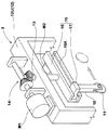
前記切断装置3は、前記コンベヤ2A、2B間の切断位置で、前記コード入りテープSを、その長さ方向Fの前端から切断長さK毎に切断する。これにより図6(B)に示すように、長さ方向両端が前記長さ方向Fに対して角度θで傾く切断縁E2とし、かつ巾方向両側を前記側縁E1とする平行四辺形状のテープ切断片S1を順次形成する。本例の切断装置3は、図3に概念的に示す如く、前記搬送コンベヤ2を跨る門型フレーム12の上枠材12Uに、支軸13を垂直に枢着している。この支軸13は、前記上枠材12Uに固定のモータM1に、例えばギヤー等を用いた伝達手段14を介して連結するとともに、その下端には、ガイド手段15を介して前記カッタ11を走行自在に取り付けている。前記ガイド手段15は、ガイド溝16Aを有する案内レール16と、前記ガイド溝16Aに沿って水平に走行自在な走行片17とを具え、該走行片17からのびるカッタホルダ18下端には、例えば円板状のカッタ11を走行方向に沿って回転自在に枢着している。なお前記走行片17は、案内レール16に固定のモータM2によって走行できる。
The
従って、前記切断装置3は、モータM1の作動により、前記案内レール16の向きを調整でき、カッタ11の切断角度θをタイヤのカテゴリに応じて適宜設定できる。なお前記カッタ11として、下降してコード入りテープSを押し切るギロチン状の押切刃であってもよく、係る場合には、カッタ11を昇降させる昇降具として、シリンダー等が好適に用いうる。なお搬送コンベヤ2には、切断位置からのコンベヤ2Bへの送り量を制御することにより前記切断長さKを調整する調整手段(図示しない)が配される。
Therefore, the
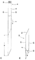
次に、前記移し替え具5は、図2、4に示すように、テープ切断片S1を前記コンベヤ2B上の受け取り位置Q1で受け取って、整列コンベヤ4上の移し替え位置Q2に移し替える。具体的には、本例の移し替え具5は、前記コンベヤ2B及び整列コンベヤ4の上方を通って長さ方向Fにのびる移し替えコンベヤ21であってフレーム19に昇降手段20を介して昇降自在に配される。この移し替えコンベヤ21は、本例では、搬送面21Sを下向きとしたベルトコンベヤであって、コンベヤベルト内周面側に装着するマグネット(図示しない)によって、コンベヤベルト下面でテープ切断片S1を吸着して長さ方向Fに搬送しうる。
Next, as shown in FIGS. 2 and 4, the
この移し替えコンベヤ21は、その搬送面21Sが、コンベヤ2B上のテープ切断片S1上面と略同高さとなる下降状態で、コンベヤ2Bからテープ切断片S1を吸着して受け取りしうる。その後、移し替えコンベヤ21は、上昇してコンベヤ2Bから離間した後、吸着したテープ切断片S1を、前記移し替え位置Q2の上方位置まで搬送しうる。
The
その後、移し替えコンベヤ21が下降し、吸着したテープ切断片S1を整列コンベヤ4上の移し替え位置Q2にて整列コンベヤ4に受け渡す。この受け渡しは、本例では、前記マグネットをシリンダー等によってベルト内周面から離れる向きに移動せしめ、テープ切断片S1への吸着を解除することにより行うが、マグネットを電磁石で形成し、その通電を入切りさせても良い。
Thereafter, the
なお前記昇降手段20は、本例では、前記フレーム19の上板19Aに固定されかつロッド下端に前記移し替えコンベヤ21を取り付けたシリンダー等の昇降具20Aと、前記移し替えコンベヤ21の上面から立上がりかつ前記上板19Aに設ける案内孔19Bに挿通するガイド軸20Bとから構成される場合を例示している。
In this example, the elevating means 20 rises from the upper surface of the
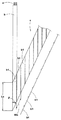
次に、前記整列コンベヤ4は、前記図1の如く、前記搬送コンベヤ2に対して前記角度θと等しい角度αで交わる移送方向Jに沿ってのびるコンベヤであって、本例では、移送方向後端側の第1のコンベヤ部4Aと、この第1のコンベヤ部4Aと乗り継ぎ自在に配される移送方向前端側の第2のコンベヤ部4Bとから構成される。
Next, as shown in FIG. 1, the
前記第1のコンベヤ部4Aは、その搬送面が前記搬送コンベヤ2のコンベヤ2Bの搬送面と同高さであり、又搬送面を前記移送方向Jに一定の移送ピッチ長さPで間欠送りしうる。この移送ピッチ長さPは、前記テープ切断片S1の移送方向の巾Wよりも大であり、従って、第1のコンベヤ部4Aは、先に第1のコンベヤ部4Aに移し替えられたテープ切断片S1の移送方向後端側の側縁E1と、次に移し替えられるテープ切断片S1の移送方向前端側の側縁E1とが接合することなく間隔Dを隔ててテープ切断片S1を整列させることができる。
The conveying surface of the
又第2のコンベヤ部4Bは、N枚のテープ切断片S1からなるタイヤ1台分のテープ切断片整列体RSを載置する長さを有しする。この第2のコンベヤ部4Bは、図5(A)に示すように、移送方向後端側が前記成形ドラム6のドラム軸心6iと平行な軸心4iにて枢支されることにより移送方向前端側を上下に傾動しうる。そして本例では、シリンダ30の作動によって上方に付勢されることにより、第2のコンベヤ部4Bの搬送面4BSを成形ドラム6の外周面に押し付ける押圧状態Y1から、搬送面4BSが成形ドラム6の外周面から離間して待機する待機状態Y2まで傾動しうる。
The
そしてこの第2のコンベヤ部4Bの搬送面4BSを成形ドラム6の外周面に押し付けつつ前記成形ドラム6の周速度V1と等しい移送速度V2で前記第2のコンベヤ部4Bを運転することにより、図5(B)に示すように、前記第2のコンベヤ部4B上のテープ切断片整列体RSを成形ドラム6の外周面に転写して貼り付けることができる。
By operating the
即ち、成形ドラム6に、前記テープ切断片整列体RSからなるベルトプライを形成することができる。なお前記成形ドラム6は、トレッド形成用のドラムであって、該成形ドラム6の周囲に、他のベルトプライ、バンドプライ、トレッドゴムなどのトレッド構成部材を順次貼り付けて積層することにより、トレッド部形成用のトレッドリングを形成することができる。
That is, a belt ply made of the tape cut piece alignment body RS can be formed on the forming
次に、本発明のベルトプライの形成方法は、テープ搬入工程と、切断工程と、切断片整列工程と、転写貼付工程とを含んで構成される。 Next, the belt ply forming method of the present invention includes a tape carry-in process, a cutting process, a cut piece alignment process, and a transfer sticking process.
前記テープ搬入工程と切断工程は、従来同工程であって、前記テープ搬入工程では、コード入りテープSを、前記搬送コンベヤ2により長さ方向Fに搬入する。又切断工程では、前記搬入されたコード入りテープSを、その長さ方向Fの前端から切断長さK毎に切断し、平行四辺形状のテープ切断片を順次形成する。
The tape carrying-in process and the cutting process are the same conventional processes, and in the tape carrying-in process, the corded tape S is carried in the length direction F by the
又切断片整列工程では、移し替えコンベヤ21を用い、切断された前記テープ切断片S1を、前記コンベヤ2B上の受け取り位置Q1で受け取って、第1のコンベヤ部4A上の移し替え位置Q2に移し替える。このとき、移し替え毎に第1のコンベヤ部4Aが、テープ切断片S1の移送方向の巾Wよりも大な移送ピッチ長さPで間欠送りすることにより、先に移し替えられたテープ切断片S1の移送方向後端側の側縁E1と、次に移し替えられるテープ切断片S1の移送方向前端側の側縁E1とが接合することなく間隔Dを隔ててテープ切断片S1を整列させることができる。又本例では、第1のコンベヤ部4A上にN枚のテープ切断片S1からなるタイヤ1台分の切断片整列体RSが形成されたとき、この切断片整列体RSを第2のコンベヤ部4Bに移送する。
In the cut piece alignment step, the
又転写貼付工程では、前記第2のコンベヤ部4Bの搬送面4BSを成形ドラム6の外周面に押し付けつつ前記成形ドラム6の周速度V1と等しい移送速度V2で前記第2のコンベヤ部4Bを運転することにより、前記第2のコンベヤ部4B上のテープ切断片整列体PSを成形ドラム6の外周面に転写して貼り付ける。
In the transfer sticking step, the
このとき、前記移送ピッチ長さPは、次式(1)、(2)を充足することが必要である。
P=L/N −−−(1)
L/W>N>L/W−1 −−−(2)
At this time, the transfer pitch length P needs to satisfy the following expressions (1) and (2).
P = L / N --- (1)
L / W>N> L / W-1 (2)
ここで、記号Lは、成形ドラム6の周長であって、形成するタイヤの直径によって定まる。又記号Wはテープ切断片S1の移送方向の巾であって、一定に設定される。従って、前記式(2)により、タイヤ1台分の切断片整列体RSを形成するためのテープ切断片S1の枚数Nを設定することができ、又式(2)から、その時の移送ピッチ長さPを設定することができる。
Here, the symbol L is the circumference of the forming
即ち、このベルトプライ形成方法では、テープ切断片S1間の間隔Dを調整することで、成形ドラムの周長Lにあったベルトプライを成形することができ、直径が異なるタイヤへの適応を図ることができる。またこの方法によって形成されたベルトプライは、テープ切断片間の重なり部が形成されないため、この重なり部に起因する剛性の不均一を抑制できる。なお前記間隔Dによる剛性変化は、重なり部による剛性変化よりも小であり、しかも前記式(1)、(2)を充足することで、前記間隔DをW/Nよりも小と、最小限にとどめることができる。従って、タイヤの走行性能に影響を与えることなく、かつ周方向の剛性不均一を最小限にとどめてユニフォミティーを向上することができる。なおユニフォミティーの向上のために、前記間隔Dは1.0mmよりも小であることが好ましい。 That is, in this belt ply forming method, the belt ply suitable for the circumferential length L of the forming drum can be formed by adjusting the distance D between the tape cut pieces S1, and the belt ply can be applied to tires having different diameters. be able to. Further, since the belt ply formed by this method does not form an overlapping portion between the tape cut pieces, it is possible to suppress nonuniform rigidity due to the overlapping portion. Note that the change in rigidity due to the distance D is smaller than the change in rigidity due to the overlapping portion, and by satisfying the equations (1) and (2), the distance D is less than W / N. It can be kept in. Therefore, the uniformity can be improved without affecting the running performance of the tire and minimizing the uneven rigidity in the circumferential direction. In order to improve uniformity, the distance D is preferably smaller than 1.0 mm.
以上、本発明の特に好ましい実施形態について詳述したが、本発明は図示の実施形態に限定されることなく、種々の態様に変形して実施しうる。 As mentioned above, although especially preferable embodiment of this invention was explained in full detail, this invention is not limited to embodiment of illustration, It can deform | transform and implement in a various aspect.
2 搬送コンベヤ
4 整列コンベヤ
4B コンベヤ部
6 成形ドラム
10 タイヤコード
D 間隔
E1 側縁
E2 切断縁
F 長さ方向
J 移送方向
K 切断長さ
RS 切断片整列体
S コード入りテープ
S1 テープ切断片
2
Claims (3)
前記搬入されるコード入りテープを、前記長さ方向の前端から切断長さ毎に切断し、長さ方向両端が前記長さ方向に対して角度θで傾く切断縁としかつ巾方向両側を前記側縁とする平行四辺形状のテープ切断片を順次形成する切断工程と、
切断された前記テープ切断片を、前記搬送コンベヤに対して前記角度θと等しい角度で交わる移送方向にのびかつ該移送方向に一定の移送ピッチ長さPで間欠送りする整列コンベヤ上に順次移し替えすることにより、先に整列コンベヤに移し替えられたテープ切断片の移送方向後端側の側縁と、次に移し替えられるテープ切断片の移送方向前端側の側縁とが接合することなく間隔を隔ててテープ切断片を整列させる切断片整列工程とを具え、
しかも前記整列コンベヤは、N枚のテープ切断片からなるタイヤ1台分の切断片整列体を載置するコンベヤ部を移送方向前端側に有し、
かつこのコンベヤ部の搬送面を成形ドラムの外周面に押し付けつつ前記成形ドラムの周速度と等しい移送速度で前記コンベヤ部を運転することにより、前記コンベヤ部上のテープ切断片整列体を成形ドラムの外周面に転写して貼り付ける転写貼付工程を行うとともに、
前記移送ピッチ長さPは、次式(1)、(2)を充足することを特徴とするベルトプライの形成方法。
P=L/N −−−(1)
L/W>N>L/W−1 −−−(2)
(式中、Lは成形ドラムの周長、Wはテープ切断片の移送方向の巾である。) Tape carry-in, in which an array of tire cords aligned in parallel with each other is covered with rubber, and a non-vulcanized cord tape with a narrow band shape whose both side edges are parallel to the tire cord is carried in the length direction by a conveyor. Process,
The corded tape to be loaded is cut at each cutting length from the front end in the length direction, both ends in the length direction are cut edges inclined at an angle θ with respect to the length direction, and both sides in the width direction are on the side A cutting step of sequentially forming parallelogram-shaped tape cutting pieces as edges;
The cut pieces of tape that have been cut extend in the transfer direction that intersects the transport conveyor at an angle equal to the angle θ, and are sequentially transferred onto an alignment conveyor that intermittently feeds the transfer direction at a constant transfer pitch length P in the transfer direction. By doing so, the side edge on the rear end side in the transfer direction of the tape cut piece transferred to the alignment conveyor and the side edge on the front end side in the transfer direction of the tape cut piece to be transferred next are not joined to each other. A cutting piece aligning step for aligning the tape cutting pieces with a gap therebetween,
And the said alignment conveyor has the conveyor part which mounts the cutting piece alignment body for one tire which consists of N pieces of tape cutting pieces in the transfer direction front end side,
And by operating the conveyor unit at a transfer speed equal to the peripheral speed of the molding drum while pressing the conveying surface of the conveyor unit against the outer peripheral surface of the molding drum, the tape cut piece alignment body on the conveyor unit is While performing a transfer pasting process to transfer and paste to the outer peripheral surface,
The transfer pitch length P satisfies the following expressions (1) and (2), and the belt ply forming method is characterized by:
P = L / N --- (1)
L / W>N> L / W-1 (2)
(In the formula, L is the circumferential length of the forming drum, and W is the width of the tape cut piece in the transfer direction.)
Priority Applications (1)
| Application Number | Priority Date | Filing Date | Title |
|---|---|---|---|
| JP2011016998A JP5695432B2 (en) | 2011-01-28 | 2011-01-28 | Belt ply forming method |
Applications Claiming Priority (1)
| Application Number | Priority Date | Filing Date | Title |
|---|---|---|---|
| JP2011016998A JP5695432B2 (en) | 2011-01-28 | 2011-01-28 | Belt ply forming method |
Publications (2)
| Publication Number | Publication Date |
|---|---|
| JP2012157975A true JP2012157975A (en) | 2012-08-23 |
| JP5695432B2 JP5695432B2 (en) | 2015-04-08 |
Family
ID=46838937
Family Applications (1)
| Application Number | Title | Priority Date | Filing Date |
|---|---|---|---|
| JP2011016998A Active JP5695432B2 (en) | 2011-01-28 | 2011-01-28 | Belt ply forming method |
Country Status (1)
| Country | Link |
|---|---|
| JP (1) | JP5695432B2 (en) |
Cited By (1)
| Publication number | Priority date | Publication date | Assignee | Title |
|---|---|---|---|---|
| CN109968710A (en) * | 2017-12-28 | 2019-07-05 | 东洋橡胶工业株式会社 | The manufacturing method and manufacturing device of belt for tire |
Citations (7)
| Publication number | Priority date | Publication date | Assignee | Title |
|---|---|---|---|---|
| JPS63116838A (en) * | 1986-11-06 | 1988-05-21 | Bridgestone Corp | Apparatus for adhering tire constitutional member |
| JP2003251711A (en) * | 2002-03-01 | 2003-09-09 | Toyo Tire & Rubber Co Ltd | Apparatus and method for molding belt of tire |
| JP2004142218A (en) * | 2002-10-23 | 2004-05-20 | Sumitomo Rubber Ind Ltd | Method for feeding tire ply and device using the method |
| JP2005186732A (en) * | 2003-12-25 | 2005-07-14 | Yokohama Rubber Co Ltd:The | Pneumatic tire and its manufacturing method |
| JP2008126531A (en) * | 2006-11-21 | 2008-06-05 | Bridgestone Corp | Manufacturing device of tire constituent member |
| WO2009034400A1 (en) * | 2007-09-10 | 2009-03-19 | Pirelli Tyre S.P.A. | Process for manufacturing a reinforcing structure for vehicle tyres |
| JP2010513071A (en) * | 2006-12-22 | 2010-04-30 | ピレリ・タイヤ・ソチエタ・ペル・アツィオーニ | Method for manufacturing tires by application of strips having different widths |
-
2011
- 2011-01-28 JP JP2011016998A patent/JP5695432B2/en active Active
Patent Citations (7)
| Publication number | Priority date | Publication date | Assignee | Title |
|---|---|---|---|---|
| JPS63116838A (en) * | 1986-11-06 | 1988-05-21 | Bridgestone Corp | Apparatus for adhering tire constitutional member |
| JP2003251711A (en) * | 2002-03-01 | 2003-09-09 | Toyo Tire & Rubber Co Ltd | Apparatus and method for molding belt of tire |
| JP2004142218A (en) * | 2002-10-23 | 2004-05-20 | Sumitomo Rubber Ind Ltd | Method for feeding tire ply and device using the method |
| JP2005186732A (en) * | 2003-12-25 | 2005-07-14 | Yokohama Rubber Co Ltd:The | Pneumatic tire and its manufacturing method |
| JP2008126531A (en) * | 2006-11-21 | 2008-06-05 | Bridgestone Corp | Manufacturing device of tire constituent member |
| JP2010513071A (en) * | 2006-12-22 | 2010-04-30 | ピレリ・タイヤ・ソチエタ・ペル・アツィオーニ | Method for manufacturing tires by application of strips having different widths |
| WO2009034400A1 (en) * | 2007-09-10 | 2009-03-19 | Pirelli Tyre S.P.A. | Process for manufacturing a reinforcing structure for vehicle tyres |
Cited By (2)
| Publication number | Priority date | Publication date | Assignee | Title |
|---|---|---|---|---|
| CN109968710A (en) * | 2017-12-28 | 2019-07-05 | 东洋橡胶工业株式会社 | The manufacturing method and manufacturing device of belt for tire |
| CN109968710B (en) * | 2017-12-28 | 2021-03-12 | 东洋橡胶工业株式会社 | Method and apparatus for manufacturing tire belt |
Also Published As
| Publication number | Publication date |
|---|---|
| JP5695432B2 (en) | 2015-04-08 |
Similar Documents
| Publication | Publication Date | Title |
|---|---|---|
| JP3625483B2 (en) | Strip material alignment splicing apparatus and method | |
| WO2006106562A1 (en) | Method and apparatus for manufacturing belt for tire | |
| TW201311434A (en) | Method and device for manufacturing a green tyre | |
| JP4238040B2 (en) | Tire reinforcement layer forming device | |
| US6613177B1 (en) | Process and apparatus for the production of strip joint member | |
| JP2013082173A (en) | Method and apparatus for molding tire component | |
| WO2007007405A1 (en) | Method and device for producing carcass ply | |
| JP4893675B2 (en) | Belt member manufacturing apparatus and method | |
| JP4600830B2 (en) | Method and apparatus for transferring sheet-like member | |
| EP2186630B1 (en) | Device and method for manufacturing sheet with cords | |
| JP5810135B2 (en) | Device and method for attaching a belt-shaped tire member | |
| JP5695432B2 (en) | Belt ply forming method | |
| WO2007010592A1 (en) | Method of manufacturing belt member | |
| JP5209951B2 (en) | Manufacturing method and manufacturing apparatus for tire ply | |
| JP2010208109A (en) | Molding method and apparatus of belt-like rubber member | |
| TWI687305B (en) | Cutting station for a tire building machine and method performed therein | |
| JP4281862B2 (en) | Banding material joining method and apparatus | |
| JP4816860B2 (en) | Method and apparatus for forming sheet-like member | |
| JP4022104B2 (en) | Strip piece assembly manufacturing method and strip piece assembly manufacturing apparatus used therefor | |
| TWI785001B (en) | Conveying apparatus and method for conveying a tire layer | |
| JP2018024149A (en) | Transporting and attaching device for ply material | |
| JP4653377B2 (en) | Strip piece assembly manufacturing method and strip piece assembly manufacturing apparatus used therefor | |
| JP2004018187A (en) | Method of manufacturing strip piece junction and manufacturing device of strip piece junction used for it | |
| JP4894080B2 (en) | Method and apparatus for manufacturing carcass member | |
| CN110815889B (en) | Transport system |
Legal Events
| Date | Code | Title | Description |
|---|---|---|---|
| A621 | Written request for application examination |
Free format text: JAPANESE INTERMEDIATE CODE: A621 Effective date: 20131219 |
|
| A977 | Report on retrieval |
Free format text: JAPANESE INTERMEDIATE CODE: A971007 Effective date: 20140703 |
|
| A131 | Notification of reasons for refusal |
Free format text: JAPANESE INTERMEDIATE CODE: A131 Effective date: 20140708 |
|
| A521 | Request for written amendment filed |
Free format text: JAPANESE INTERMEDIATE CODE: A523 Effective date: 20140808 |
|
| TRDD | Decision of grant or rejection written | ||
| A01 | Written decision to grant a patent or to grant a registration (utility model) |
Free format text: JAPANESE INTERMEDIATE CODE: A01 Effective date: 20150127 |
|
| A61 | First payment of annual fees (during grant procedure) |
Free format text: JAPANESE INTERMEDIATE CODE: A61 Effective date: 20150206 |
|
| R150 | Certificate of patent or registration of utility model |
Ref document number: 5695432 Country of ref document: JP Free format text: JAPANESE INTERMEDIATE CODE: R150 |
|
| R250 | Receipt of annual fees |
Free format text: JAPANESE INTERMEDIATE CODE: R250 |
|
| R250 | Receipt of annual fees |
Free format text: JAPANESE INTERMEDIATE CODE: R250 |
|
| R250 | Receipt of annual fees |
Free format text: JAPANESE INTERMEDIATE CODE: R250 |
|
| R250 | Receipt of annual fees |
Free format text: JAPANESE INTERMEDIATE CODE: R250 |
|
| R250 | Receipt of annual fees |
Free format text: JAPANESE INTERMEDIATE CODE: R250 |
|
| R250 | Receipt of annual fees |
Free format text: JAPANESE INTERMEDIATE CODE: R250 |