JP2012157199A - Control device of electric vehicle - Google Patents
Control device of electric vehicle Download PDFInfo
- Publication number
- JP2012157199A JP2012157199A JP2011015572A JP2011015572A JP2012157199A JP 2012157199 A JP2012157199 A JP 2012157199A JP 2011015572 A JP2011015572 A JP 2011015572A JP 2011015572 A JP2011015572 A JP 2011015572A JP 2012157199 A JP2012157199 A JP 2012157199A
- Authority
- JP
- Japan
- Prior art keywords
- motor
- shift
- speed
- output
- electric vehicle
- Prior art date
- Legal status (The legal status is an assumption and is not a legal conclusion. Google has not performed a legal analysis and makes no representation as to the accuracy of the status listed.)
- Granted
Links
Images


Classifications
-
- Y—GENERAL TAGGING OF NEW TECHNOLOGICAL DEVELOPMENTS; GENERAL TAGGING OF CROSS-SECTIONAL TECHNOLOGIES SPANNING OVER SEVERAL SECTIONS OF THE IPC; TECHNICAL SUBJECTS COVERED BY FORMER USPC CROSS-REFERENCE ART COLLECTIONS [XRACs] AND DIGESTS
- Y02—TECHNOLOGIES OR APPLICATIONS FOR MITIGATION OR ADAPTATION AGAINST CLIMATE CHANGE
- Y02T—CLIMATE CHANGE MITIGATION TECHNOLOGIES RELATED TO TRANSPORTATION
- Y02T10/00—Road transport of goods or passengers
- Y02T10/60—Other road transportation technologies with climate change mitigation effect
- Y02T10/72—Electric energy management in electromobility
Abstract
Description
この発明は電気自動車の制御装置に関し、より具体的にはクラッチが除去された変速機を備えた電気自動車の制御装置に関する。 The present invention relates to a control device for an electric vehicle, and more specifically to a control device for an electric vehicle including a transmission from which a clutch is removed.
車両に搭載されるモータをアクセル開度に応じて算出されるトルク指令値に基づいて制御すると共に、クラッチを介して変速機に接続し、クラッチが操作されたとき、モータのフリクション分だけトルク指令値を減少し、モータの回転数を低下させてからクラッチの接続が行われるようにした電気自動車の制御装置は知られており、その例としては下記の特許文献1記載の技術を挙げることができる。
The motor mounted on the vehicle is controlled based on the torque command value calculated according to the accelerator opening, and connected to the transmission via the clutch. When the clutch is operated, the torque command is equivalent to the motor friction. There is known a control apparatus for an electric vehicle in which the clutch is connected after the value is reduced and the number of revolutions of the motor is reduced, and as an example, a technique described in
特許文献1記載の技術にあっては、さらに、モータが車速に対して規定された回転数以上で駆動されていた場合、トルク指令値が所定値以下となるように制御してクラッチの接続が行われるように構成している。
In the technique described in
特許文献1記載の技術にあっては、上記のように構成することで、モータの出力トルクと回転数が高い状態でのクラッチの接続を回避することでクラッチとモータの保護を図っているが、モータと変速機を接続するクラッチを備えているため、構成が複雑となると共に、重量やコストが増加する不都合がある。
In the technique described in
この発明の目的は上記した課題を解決し、モータと変速機を備えた電気自動車において、モータと変速機を接続するクラッチを不要にして構成を簡易にすると共に、重量やコストの増加を抑制するようにした電気自動車の制御装置を提供することにある。 SUMMARY OF THE INVENTION An object of the present invention is to solve the above-mentioned problems, and in an electric vehicle equipped with a motor and a transmission, a clutch for connecting the motor and the transmission is not required and the configuration is simplified, and an increase in weight and cost is suppressed. An object of the present invention is to provide a control device for an electric vehicle.
上記した課題を解決するために、請求項1にあっては、車両に搭載されるモータと、少なくとも運転者に操作されるアクセルペダルの開度に応じて前記モータの出力を制御するモータ出力制御手段と、変速指示がなされたとき、前記モータに接続される入力軸と駆動輪に接続される出力軸の間に配置される複数個の変速段ギヤを切り替える噛み合い式クラッチを有する変速機とを備えた電気自動車の制御装置において、前記モータ出力制御手段は、前記変速指示がなされたとき、前記噛み合い式クラッチが前記複数個の変速段ギヤを切り替える前に、前記モータの出力を零あるいはその近傍からなる所定値に制御する如く構成した。
In order to solve the above-described problem, in
請求項2に係る電気自動車の制御装置にあっては、前記モータ出力制御手段によって前記変速指示がなされたときに前記モータの出力を所定値に制御された後、前記噛合い式クラッチを開放し、前記モータ出力制御手段によって前記入力軸と出力軸の差回転が所定範囲となるように制御された後、前記噛み合い式クラッチを係合する如く構成した。
In the control apparatus for an electric vehicle according to
請求項3に係る電気自動車の制御装置にあっては、前記モータ出力制御手段は、前記変速指示がなされたとき、前記モータの出力を、前記所定値に前記モータの回転子と前記入力軸のフリクショントルクに相当する値を加算して得た値に制御する如く構成した。
In the control apparatus for an electric vehicle according to
請求項4に係る電気自動車の制御装置にあっては、前記モータ出力制御手段は、前記フリクショントルクに相当する値を前記変速機の油温と前記入力軸の回転数に基づいて変更する如く構成した。 The electric vehicle control device according to claim 4, wherein the motor output control means is configured to change a value corresponding to the friction torque based on an oil temperature of the transmission and a rotational speed of the input shaft. did.
請求項5に係る電気自動車の制御装置にあっては、前記複数個の変速段ギヤは、前記モータの高速側のノイズピークが前記車両の設定最高車速を超えた領域で発生するように変速比が設定される如く構成した。
In the control apparatus for an electric vehicle according to
請求項1にあっては、運転者に操作されるアクセルペダルの開度に応じて車両に搭載されるモータの出力を制御するモータ出力制御手段と、変速指示がなされたとき、モータに接続される入力軸と駆動輪に接続される出力軸の間に配置される複数個の変速段ギヤを切り替える噛み合い式クラッチを有する変速機とを備えた電気自動車の制御装置において、モータ出力制御手段は、変速指示がなされたとき、噛み合い式クラッチが変速段ギヤを切り替える前に、モータの出力を零あるいはその近傍からなる所定値に制御する如く構成したので、変速指示に応じてモータの出力を零あるいはその近傍からなる所定値に制御することでモータと変速機を接続するクラッチを不要にでき、よって構成を簡易にできると共に、重量やコストの増加を抑制することができる。 According to the first aspect of the present invention, the motor output control means for controlling the output of the motor mounted on the vehicle according to the opening degree of the accelerator pedal operated by the driver, and when the gear shift instruction is issued, the motor output control means is connected to the motor. In the control apparatus for an electric vehicle, the motor output control means includes: a transmission having a meshing clutch that switches a plurality of shift gears arranged between the input shaft and the output shaft connected to the drive wheel. When the gear shift instruction is given, the motor output is controlled to a predetermined value consisting of zero or the vicinity thereof before the meshing clutch switches the shift gear, so the motor output is set to zero or zero according to the gear shift instruction. By controlling to a predetermined value in the vicinity, the clutch that connects the motor and transmission can be eliminated, thereby simplifying the configuration and suppressing an increase in weight and cost. Rukoto can.
請求項2に係る電気自動車の制御装置にあっては、モータ出力制御手段によって変速指示がなされたときにモータの出力を所定値に制御された後、噛合い式クラッチを開放し、モータ出力制御手段によって入力軸と出力軸の差回転が所定範囲となるように制御された後、噛み合い式クラッチを係合する如く構成したので、上記した効果に加え、変速段ギヤを一層滑らかに切り替えることができ、噛み合い式クラッチ係合時の異音を低下できると共に、噛み合い式クラッチの耐久性を向上させることができる。
In the control apparatus for an electric vehicle according to
請求項3に係る電気自動車の制御装置にあっては、モータ出力制御手段は、変速指示がなされたとき、モータの出力を、所定値にモータの回転子と入力軸のフリクショントルクに相当する値を加算して得た値に制御する如く構成したので、上記した効果に加え、噛み合い式クラッチに作用する負荷を擬似的にゼロにできるため、噛み合い式クラッチの耐久性を向上させることができる。
In the electric vehicle control apparatus according to
請求項4に係る電気自動車の制御装置にあっては、モータ出力制御手段は、フリクショントルクに相当する値を変速機の油温と入力軸の回転数に基づいて変更する如く構成したので、一層確実に噛み合い式クラッチに作用する負荷を擬似的にゼロにすることを実現することができる。 In the control apparatus for an electric vehicle according to the fourth aspect, the motor output control means is configured to change the value corresponding to the friction torque based on the oil temperature of the transmission and the rotational speed of the input shaft. It is possible to realize that the load acting on the meshing clutch is surely made to be zero.
請求項5に係る電気自動車の制御装置にあっては、複数個の変速段ギヤは、モータの高速側のノイズピークが車両の設定最高車速を超えた領域で発生するように変速比が設定される如く構成したので、上記した効果に加え、例えば車両の走行速度が低いときに小さい変速比のギヤに切り替えて低速側のノイズピークの車速範囲を狭くし、走行速度が高いときに大きい変速比のギヤに切り替えて高速側のノイズピークを(設定最高車速を超えて)より高速側に移すことも可能となり、よって常用運転域でのNV(Noise Vibration。騒音)を低減させることができる。
In the control apparatus for an electric vehicle according to
以下、添付図面を参照してこの発明に係る車両の制御装置を実施するための形態について説明する。 DESCRIPTION OF EXEMPLARY EMBODIMENTS Hereinafter, embodiments for implementing a vehicle control apparatus according to the invention will be described with reference to the accompanying drawings.
図1は、この発明の第1実施例に係る電気自動車の制御装置を全体的に示す概略図、図2と図3は図1に示す変速機のスケルトン図である。 FIG. 1 is a schematic diagram generally showing a control apparatus for an electric vehicle according to a first embodiment of the present invention, and FIGS. 2 and 3 are skeleton diagrams of the transmission shown in FIG.
図1において符号10は電気自動車(以下「車両」という)10を模式的に示し、車両10にはモータ(電動機。図で「MOT」と示す)12が搭載される。モータ12は具体的にはDCブラシレスモータからなり、後述するようにU,V,Wの3相電流を通電されて動作する。
In FIG. 1,
モータ12は駆動軸14を介して手動変速機に類似する変速機(図で「MT」と示す)16に接続される。変速機16はモータ12の出力を変速し、駆動輪(車輪)20に伝達する。
The
モータ12は通電されるとき、回転して駆動輪20を駆動して車両10を走行させる。一方、モータ12は通電されないときは空転すると共に、駆動輪20から駆動されるとき、駆動軸14の回転によって生じた運動エネルギを電気エネルギに変換して出力する回生機能を有する発電機(ジェネレータ)として機能する。
When the
モータ12は、パワードライブユニット(PDU)22を介してバッテリ(BATT)24に接続される。PDU22はインバータを備え、バッテリ24から供給(放電)される直流(電力)を交流に変換してモータ12に供給すると共に、モータ12の回生動作によって発電された交流を直流に変換してバッテリ24に供給する。
The
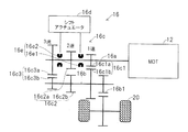
図2に示す如く、変速機16はモータ12に(駆動軸14を介して)接続される入力軸16aと、駆動輪20に接続される出力軸16bと、その間に配置される複数個の変速段ギヤ16cと、モータなどからなるシフトアクチュエータ16dと、シフトアクチュエータ16dに接続される複数個の噛み合い式クラッチ16eとを備える。
As shown in FIG. 2, the
変速段ギヤ16cは具体的には1速、2速、3速ギヤ16c1,16c2,16c3からなる。入力軸16aにはそのうちのドライブ側の1速、2速、3速ドライブギヤ16c1a,16c2a,16c3aが相対回転自在に配置される一方、出力軸16bには、それらに噛合するドリブン側の1速、2速、3速ドリブンギヤ16c1b,16c2b,16c3bが相対回転不能に固定される。
Specifically, the
変速段ギヤ16cは、モータ12の高速側のノイズピークが車両10の設定最高車速(例えば180km/h)を超えた領域で発生するように変速比が設定されるように構成される。それについては後述する。
The
出力軸16bにはファイナルドライブギヤ16b1が固定される。ファイナルドライブギヤ16b1はファイナルドリブンギヤなどのギヤ群とディファレンシャル機構(全て図示せず)を介して駆動輪20に接続される。
A final drive gear 16b1 is fixed to the
複数個の噛み合い式クラッチ16eは変速段ギヤ16cの間に配置される第1、第2の噛み合い式クラッチ16e1,16e2からなり、それぞれ入力軸16aに相対回転不能かつ軸方向に移動自在にスプライン結合されたスリーブドグクラッチと、その両側において1速、2速、3速ドライブギヤ16c1a,16c2a,16c3aに設けられたドグクラッチ、回転を同期させるシンクロ機構を有する。
The plurality of meshing
スリーブドグクラッチはシフトアクチュエータ16dに取り付けられ、シフトアクチュエータ16dが通電されて入力軸16aの軸方向に駆動されるとき、それに伴って図示の中立位置から移動して対応するギヤ16cを入力軸16aに固定する。尚、第1の噛み合い式クラッチ16e1は1速ドライブギヤ16c1aに対してのみ移動可能に構成される。
The sleeve dog clutch is attached to the
変速段の確立について説明すると、シフトアクチュエータ16dを介して第1の噛み合い式クラッチ16e1を図2で右に移動させると、1速ドライブギヤ16c1aが入力軸16aに係合し、モータ12から入力軸16aに入力された回転駆動力(入力トルク)は1速ドライブギヤ16c1aを回転させる。
The establishment of the gear position will be described. When the first meshing clutch 16e1 is moved to the right in FIG. 2 via the
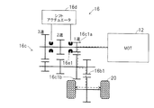
図3に示す如く、1速ドライブギヤ16c1aの回転はそれに噛合する1速ドリブンギヤ16c1bに伝えられて出力軸16bを回転させることで1速(変速段)が確立される。出力軸16bの回転はファイナルドライブギヤ16b1からファイナルドリブンギヤとディファレンシャル機構などに伝えられ、さらには駆動輪20に伝えられて車両10を1速で前進走行させる。
As shown in FIG. 3, the rotation of the first-speed drive gear 16c1a is transmitted to the first-speed driven gear 16c1b meshing with the first-speed drive gear 16c1a, and the first-speed (shift stage) is established by rotating the
また、その状態でモータ12の回転方向を反転させると、モータ12の回転は1速ドライブギヤ16c1aと1速ドリブンギヤ16c1bに伝えられて出力軸16bを逆方向に回転させることで後進1速(変速段)が確立される。
Further, if the rotation direction of the
第2の噛み合い式クラッチ16e2を図2で右に移動させて2速ドライブギヤ16c2aを入力軸16aに係合すると、同様に入力軸16aの回転駆動力は2速ドライブギヤ16c2aと2速ドリブンギヤ16c2bを介して出力軸16bを回転させることで2速(変速段)が確立される。
When the second meshing clutch 16e2 is moved to the right in FIG. 2 to engage the second-speed drive gear 16c2a with the
第2の噛み合い式クラッチ16e2を図2で左に移動させて3速ドライブギヤ16c3aを入力軸16aに係合すると、入力軸16aの回転駆動力は3速ドライブギヤ16c3aと3速ドリブンギヤ16c3bを介して出力軸16bを回転させることで3速(変速段)が確立される。
When the second meshing clutch 16e2 is moved to the left in FIG. 2 to engage the third speed drive gear 16c3a with the
このように、この実施例において変速機16はAMT(Automated Manual Transmission)、即ち、自動化されたマニュアルトランスミッション(手動変速機)として構成される。
Thus, in this embodiment, the
図1の説明に戻ると、車両10の運転席にはシフト(レンジセレクト)レバー30が配置される。シフトレバー30は運転者の手動操作によって図示のようなシフトパターン30aを移動(選択)自在に構成される。シフトパターン30aはP,R,N,Dからなるメインレンジ30a1と、Dレンジから分岐された+/−からなるサブレンジ30a2を備える。
Returning to the description of FIG. 1, a shift (range select)
サブレンジ30a2の+は現在の変速段からのシフトアップを、−は現在の変速段からのシフトダウンを示す。サブレンジ30a2は運転者がメインレンジ30a1においてDレンジを選択しているときのみ使用可能に構成される。運転者がシフトレバー30をサブレンジ30a2の+に位置させたときはシフトアップ(変速)指示、−に位置させたときはシフトダウン(変速)指示がなされたことを意味する。
In the sub-range 30a2, + indicates a shift up from the current gear, and-indicates a shift down from the current gear. The subrange 30a2 is configured to be usable only when the driver selects the D range in the main range 30a1. When the driver places the
尚、運転者によってDレンジが選択されている場合、サブレンジ30a2でのシフトレバー操作による変速指示に応じた変速の他に、車速とアクセル開度からシフトマップを検索して1速から3速の間で自動的に変速される。 In addition, when the D range is selected by the driver, in addition to the shift according to the shift instruction by the shift lever operation in the sub-range 30a2, the shift map is searched from the vehicle speed and the accelerator opening to change from the first speed to the third speed. It is automatically shifted between.
シフトレバー30の付近にはシフトレバーポジションセンサ32が配置され、運転者によって選択されたメインレンジあるいはサブレンジでのシフトレバー30の位置を示す出力を生じる。
A shift
また、変速機16のケース底面のATF(Automatic Transmission Fluid。作動油)のリザーバには油温センサ34が設けられ、油温TATF(ATFの温度)を示す出力を生じる。
An
駆動輪20の付近にはディスクブレーキなどのブレーキ36が設けられると共に、ブレーキ36にはブレーキユニット40が接続される。さらに車両10の運転席には運転者の操作自在にブレーキペダル42が設けられる。
A
ブレーキユニット40は油圧ブースタと電動サーボを備え、動作するとき、ブレーキペダル42による運転者の操作と独立にブレーキ36を作動させて車両10を制動する。ブレーキペダル42の付近にはブレーキ開度センサ44が設けられ、ブレーキ開度、即ち、運転者によるブレーキペダル42の踏み込み量に応じた出力を生じる。
The
同様に車両10の運転席には運転者の操作自在にアクセルペダル46が設けられると共に、その付近にはアクセル開度センサ48が設けられ、アクセル開度、即ち、運転者によるアクセルペダル46の踏み込み量に応じた出力を生じる。駆動輪20のドライブ軸の付近には車速センサ50が設けられ、車両10の走行速度(車速)を示す信号を出力する。
Similarly, an
ブレーキ開度センサ44とアクセル開度センサ48の出力はMOT/ECU52に送られると共に、シフトレバーポジションセンサ32と油温センサ34と車速センサ50の出力はAMT/ECU54に送られる。
The outputs of the
さらに、ブレーキユニット40の動作を制御するBRK/ECU56も設けられる。BRK/ECU56は必要に応じてブレーキ指示(動作指示)を送り、ブレーキユニット40を動作させる。
Further, a BRK /
MOT/ECU52とAMT/ECU54とBRK/ECU56はそれぞれ、CPU,ROM,RAMなどを有するマイクロコンピュータを備える。これらECU52,54,56は信号線60によって接続され、相互に通信して情報を取得可能なように構成される。
Each of the MOT /
さらにMOT/ECU52にはモータ12に配置されたレゾルバなどを介して回転子(ROT)の位相と回転数についての情報が送られると共に、PDU22に配置された電圧・電流センサなどから通電電流(と通電電圧)を示す情報が送られる。
Further, the MOT /
MOT/ECU52はそれらセンサ出力に基づき、即ち、少なくとも運転者に操作されるアクセルペダル46の開度に応じて所望のトルクが生じるように制御値を算出してモータ12の出力を制御する。
The MOT /
図4はMOT/ECU52の制御値の算出動作を機能的に示すブロック図である。
FIG. 4 is a block diagram functionally showing the control value calculation operation of the MOT /
以下説明すると、モータ12のいずれか2相(例えばU相とW相)の電流は3相/2軸変換部52aによってd−q軸上の実相電流id,iqに変換され、電流制御演算部52bに入力される。ここでdqは公知のモータのベクトル制御におけるdq変換のことである。
As will be described below, the current of any two phases (for example, the U phase and the W phase) of the
電流制御演算部52bはアクセル開度から算出されるモータトルク指令と検出されたモータ12の回転数とバッテリ24の入出力電圧とに基づいて目標とする電流指令値Id,Iqを求めると共に、前記した実相電流id,iqとの電流偏差Δid,Δiqを算出し、PI制御則を用いて下記の式1,2に従って電圧指令値VD,VQを算出する。
The current
VD=Kp×Δid+Ki×(∫Δid・dt)+C1 ・・・式1
VQ=Kp×Δiq+Ki×(∫Δiq・dt)+C2 ・・・式2
上記でKp:比例ゲイン、Ki:積分ゲイン、C1,C2:d,q軸間の干渉成分を除去するためのフィードフォワード項である。
VD = Kp × Δid + Ki × (∫Δid · dt) +
VQ = Kp × Δiq + Ki × (∫Δiq · dt) +
In the above, Kp: proportional gain, Ki: integral gain, C1, C2: d, a feedforward term for removing interference components between the q axes.
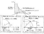
図5は図4の電圧指令値の算出処理を説明する説明図である。図5を参照してこの電圧指令値VD,VQの算出を敷衍すると、所望の動作点上の電圧指令値VD,VQは、次のように算出される。 FIG. 5 is an explanatory diagram for explaining the voltage command value calculation process of FIG. If the calculation of the voltage command values VD and VQ is considered with reference to FIG. 5, the voltage command values VD and VQ on the desired operating point are calculated as follows.
即ち、モータ12の電気角速度ωで表わされる逆起電力ωkeから求められるa点(ωke,0)に、モータ12の各相の抵抗分Rと電流指令値Id,Iqのd軸成分Idとから求められるd軸成分R×Idを加算してb点(ωke+R×Id,0)を算出する。
That is, from the resistance R of each phase of the
次いでモータ12の電気角速度ωとd軸方向のインダクタンス成分Ldと電流指令値Id,Iqのd軸成分Idとで求められるq軸成分(ω×Ld×Id)を加算し、c点(ωke+R×Id,ω×Ld×Id)を算出する。
Next, the q-axis component (ω × Ld × Id) obtained from the electrical angular velocity ω of the
次いでモータ12の各相の抵抗成分Rと電流指令値Id,Iqのq軸成分Iqとから求められるq軸成分R×Iqを加算してd点(ωke+R×Id,ω×Ld×Id+R×Iq)を算出する。
Next, the q-axis component R × Iq obtained from the resistance component R of each phase of the
次いでモータ12の電気角速度ωとq軸方向のインダクタンス成分Lqと電流指令値Id,Iqのq軸成分Iqとで求められるq軸成分(ω×Lq×Iq)を加算する。これにより、所望の動作点であるe点(ωke+R×Id−ω×Lq×Iq,ω×Ld×Id+R×Iq)を求めることができる。
Next, the q-axis component (ω × Lq × Iq) obtained from the electrical angular velocity ω of the
このようにして電圧指令値を算出することができる。算出された電圧指令値VD,VQは出力電圧監視部52cに入力され。そこでモータ過回転などの不都合が生じないように出力電圧が監視される。
In this way, the voltage command value can be calculated. The calculated voltage command values VD and VQ are input to the output
図6は出力電圧監視部52cの動作をより詳細に示すブロック図である。
FIG. 6 is a block diagram showing the operation of the output
以下説明すると、出力電圧監視部52cにおいて電流制御演算部52bで算出された電圧指令値VD,VQは制御系異常判定部52c1に入力され、そこで算出値が印加電圧リミットを超えるか否か判定される。
In the following, the voltage command values VD and VQ calculated by the current
また算出値は位相検出部52c2に入力され、そこで位相が検出され、算出値の前回値の位相を初期位相φ_initとして出力する。尚、制御系異常判定部52c1で印加電圧リミットを超えると判定されるとき、算出値の今回値の位相を初期位相φ_initとして出力する。 The calculated value is input to the phase detector 52c2, where the phase is detected, and the phase of the previous value of the calculated value is output as the initial phase φ_init. When the control system abnormality determination unit 52c1 determines that the applied voltage limit is exceeded, the phase of the current value of the calculated value is output as the initial phase φ_init.
位相制御部52c3は、モータ12にトルクを発生させない電圧指令値VD,VQの位相をゼロトルク位相φ_comとして予め記憶してするゼロトルク位相記憶部52c4を備え、そこから出力されるゼロトルク位相φ_comに近づくように例えばPI制御則を用いて出力変化分Δφを算出する。
The phase control unit 52c3 includes a zero torque phase storage unit 52c4 that stores in advance the phases of the voltage command values VD and VQ that do not cause the
位相減算部52c5は位相検出部52c2から出力される初期φ_initから出力変化分の積算値∫Δφを減算して現在位相φ_nowを算出して位相制御部52c3に入力する。このように、位相制御部52c3などではゼロトルク位相と現在位相の差が所定値以下となるまで、上記の処理が繰り返される。 The phase subtraction unit 52c5 subtracts the integrated value ∫Δφ corresponding to the output change from the initial φ_init output from the phase detection unit 52c2, and calculates the current phase φ_now and inputs it to the phase control unit 52c3. Thus, in the phase control unit 52c3 or the like, the above process is repeated until the difference between the zero torque phase and the current phase becomes a predetermined value or less.
位相制御部52c3の出力φ+Δφは出力電圧算出部52c6に送られ、そこで以下の式に従って電圧指令値が最終的に算出され、出力電圧切り替え部52cから出力される。
VD=VP×cos(φ+Δφ) ・・・式3
VQ=VP×sin(φ+Δφ) ・・・式4
上記でVP:振幅である。
The output φ + Δφ of the phase control unit 52c3 is sent to the output voltage calculation unit 52c6, where a voltage command value is finally calculated according to the following formula and output from the output
VD = VP × cos (φ + Δφ)
VQ = VP × sin (φ + Δφ) Equation 4
In the above, VP is amplitude.
図4の説明に戻ると、出力電圧監視部52cの出力は2軸/3相変換部52dに送られ、そこでU,V,W相電圧からなる3相電圧指令値に変換され、PDU22に出力される。
Returning to the description of FIG. 4, the output of the output
次いで図1に戻ってAMT/ECU54の動作を説明すると、AMT/ECU54はシフトレバーポジションセンサ32などのセンサ出力とMOT/ECU52に通信して得たアクセル開度などの情報に基づき、シフト指示を決定してシフトアクチュエータ16dを動作させる。
Next, returning to FIG. 1, the operation of the AMT /
即ち、AMT/ECU54は、後述するようにシフトマップ検索による変速指示がなされたとき、あるいは運転者からシフトレバー30を通じて変速指示がなされたとき、シフトアクチュエータ16dを動作させて噛み合い式クラッチ16eを入力軸16aに沿って移動させ、3個の変速段ギヤ16cを例えば1速から2速、3速から2速へなどと切り替える。
That is, the AMT /
上記を前提としてこの実施例に係る電気自動車の動作を説明する。 Based on the above, the operation of the electric vehicle according to this embodiment will be described.
図7はその動作を示すフロー・チャートである。尚、図示のプログラムはAMT/ECU54によって実行される。
FIG. 7 is a flowchart showing the operation. The illustrated program is executed by the AMT /
以下説明すると、S(ステップ)10においてシフトマップ検索による変速指示がなされたか、即ち、Dレンジが選択されている場合、図示しない変速制御部において車速とアクセル開度からシフトマップを検索した結果、変速指示がなされているか否か判断する。 In the following description, in S (step) 10, whether or not a shift instruction has been issued by the shift map search, that is, when the D range is selected, the shift control unit (not shown) searches the shift map from the vehicle speed and the accelerator opening, It is determined whether or not a shift instruction has been issued.
S10で否定されるときはS12に進み、運転者変速指示、即ち、サブレンジ30a2でのシフトレバー操作によって運転者から変速指示がなされたか否か判断し、否定されるときはS14に進み、現在の変速段(速度)を維持し、以降の処理をスキップする。 When the result in S10 is negative, the process proceeds to S12, where it is determined whether or not a driver shift instruction, that is, a shift instruction from the driver has been made by operating the shift lever in the subrange 30a2, and when the result is negative, the process proceeds to S14. The gear position (speed) is maintained and the subsequent processing is skipped.
他方、S12で肯定されるときはS16に進み、変速可か否か判断する。この判断は具体的には、アクセル開度から算出される必要モータトルクが変速先の変速段で要求されるモータ最大トルク未満であり、必要モータ回転数が変速先の変速段で要求されるモータ最高回転数未満か否か判断することで行う。 On the other hand, when the result in S12 is affirmative, the program proceeds to S16, in which it is determined whether or not shifting is possible. Specifically, this determination is based on a motor in which the required motor torque calculated from the accelerator opening is less than the maximum motor torque required in the shift destination gear, and the required motor rotational speed is required in the shift destination gear. This is done by judging whether it is less than the maximum speed.
S16で否定されるときはS14に進む一方、肯定されるときはS18に進み、MOTゼロトルク制御を実行する。これはS10で肯定されるときも同様であり、換言すれば変速指示がなされたとき、S18に進み、MOTゼロトルク制御が実行される。 When the result in S16 is negative, the process proceeds to S14. When the result is positive, the process proceeds to S18, and MOT zero torque control is executed. This is the same when the determination in S10 is affirmative. In other words, when a shift instruction is issued, the process proceeds to S18 and MOT zero torque control is executed.
S18のMOTゼロトルク制御は、MOT/ECU52に通信し、前記した出力電圧監視部52cの位相制御部52c3においてゼロトルク位相と現在位相の差が所定値以下となるように電圧指令値VD,VQを算出して出力させることで行われる。
The MOT zero torque control in S18 communicates with the MOT /
図8はその処理を示す説明図である。尚、同図においてd,q軸の向きを図5と相違させて示す。図示の如く、位相が90度相違する直交領域にあるときはモータ12のトルクTqは下部左欄の末尾の式によって0[Nm]に制御される。
FIG. 8 is an explanatory diagram showing the processing. In the figure, the directions of the d and q axes are different from those in FIG. As shown in the figure, when the phase is in an orthogonal region that is 90 degrees different, the torque Tq of the
一方、車速の増加に伴って弱め界磁領域にあるときは、Idが0[A](実効値)を超えるが、下部右欄の末尾の式に示す如く、Iqが0であることから、トルクTqは結果的に0[Nm]に制御される。 On the other hand, when it is in the field weakening region as the vehicle speed increases, Id exceeds 0 [A] (effective value), but Iq is 0 as shown in the last expression in the lower right column. As a result, the torque Tq is controlled to 0 [Nm].
図7フロー・チャートの説明に戻ると、次いでS20に進み、ドグクラッチを開放する。即ち、シフトアクチュエータ16dを動作させて噛み合い式クラッチ16eのスリーブドグクラッチを中立位置に戻し、S22に進み、モータ変速後回転数合わせを実行する。これは噛み合い式クラッチ16eの損傷を回避するためであり、モータイナーシャと差回転が同期回転数以上のときに行われる。
Returning to the description of the flow chart of FIG. 7, the process then proceeds to S20 to release the dog clutch. That is, the
次いでS24に進み、所望の変速段ギヤにドグクラッチを係合、即ち、シフトアクチュエータ16dを動作させて噛み合い式クラッチ16eのスリーブドグクラッチを変速先の変速段ギヤのドグクラッチに係合させる。次いでS26に進み、変速完了と判断して以降の処理をスキップする。
Next, in S24, the dog clutch is engaged with a desired gear, that is, the
上記の如く、この実施例に係る電気自動車の制御装置においては、変速指示がなされたとき、変速段ギヤが切り替えられる前に、モータ12の出力を零あるいはその近傍からなる所定値、具体的にはゼロトルクに制御する如く構成したので、変速段ギヤ16cを切り替えるのにモータ12と変速機16を接続するクラッチを不要にでき、よって構成を簡易にできると共に、重量やコストの増加を抑制することができる。
As described above, in the control apparatus for an electric vehicle according to this embodiment, when a gear shift instruction is given, the output of the
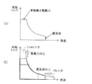
さらに、3個の変速段ギヤ16cを備えることで、上記した効果に加え、モータ12の一層の小型化を図ることができる。図9を参照して説明すると、モータ12に変速機16を接続しない場合、換言すれば変速比が固定される場合、同図(a)に示すように車速と車軸最大駆動力とは背反関係となる。
Furthermore, by providing the three
他方、この実施例にあっては3個の変速段ギヤ16cを備える変速機16を設けるように構成したので、同図(b)に示す如く、変速比を変えることで最高速と車軸トルクとを向上させることができる。換言すれば、同一の最高速と車軸トルクを実現する車軸最大駆動力を低減することができ、よってモータ12を一層小型化することができる。
On the other hand, in this embodiment, since the
さらに、3個の変速段ギヤ16cを備えることで、上記した効果に加え、変速比が固定される場合に比し、騒音(NV(Noise Vibration))を低減することができる。
Furthermore, by providing the three
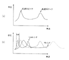
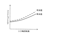
さらに、複数個の変速段ギヤ16cは、モータ12の高速側のノイズピークが車両10の設定最高車速を超えた領域で発生するように変速比が設定される如く構成される。その結果、実施例に係る車両10の騒音が図10(a)に示すような特性を有すると仮定すると、同図(b)に示す如く、車速が低いときに小さい変速比(Lowレシオ)のギヤに切り替えて低速側のノイズピークの車速範囲を狭くし、車速が高いときに大きい変速比(Hiレシオ)のギヤに切り替えて高速側のノイズピークを(想像線で示すように)設定最高車速を超えてより高速側に移すことができ、よって常用運転域での騒音を低減させることができる。
Further, the plurality of shift gears 16 c are configured such that the gear ratio is set so that the noise peak on the high speed side of the
また、変速指示がなされたときにモータの出力を所定値に制御された後、噛合い式クラッチ16eを開放し、次いで入力軸と出力軸の差回転が所定範囲となるように制御された後、噛み合い式クラッチ16eを係合する如く構成したので、上記した効果に加え、変速段ギヤ16cを一層滑らかに切り替えることができ、噛み合い式クラッチ係合時の異音を低下できると共に、噛み合い式クラッチ16eの耐久性を向上させることができる。
Also, after the output of the motor is controlled to a predetermined value when a shift instruction is given, the meshing clutch 16e is released, and then the differential rotation between the input shaft and the output shaft is controlled to be within a predetermined range. Since the meshing clutch 16e is engaged, in addition to the above-described effects, the
図11は、この発明の第2実施例に係る電気自動車の制御装置の構成を示す図6と同様の出力電圧監視部52cのブロック図である。
FIG. 11 is a block diagram of an output
第1実施例と相違する点に焦点をおいて説明すると、第2実施例にあっては、変速指示がなされたとき、モータ12の出力を、前記したゼロトルク(所定値)にモータ12の回転子と入力軸16aのフリクショントルクに相当する値を加算して得た値に制御する如く構成した。尚、この処理は図7フロー・チャートのS18で行われる。
The description will focus on the differences from the first embodiment. In the second embodiment, when a gear shift instruction is issued, the output of the
即ち、変速指示がなされたときにモータ12の出力をゼロトルクに制御することでモータ12と変速機16の間のクラッチを不要にできるが、その場合でも噛み合い式クラッチ16eのスリーブドグクラッチとそれに噛合するドライブギヤ側のドグクラッチにはモータ12の回転子と入力軸16aのフリクショントルクが作用する。第2実施例はそれに対策するようにした。
That is, the clutch between the
図12はそのフリクショントルクの特性を示す説明図である。図示の如く、フリクショントルクは入力軸16aの回転数が上昇するにつれて増加すると共に、油温TATFが低下するにつれて増加する。
FIG. 12 is an explanatory diagram showing the characteristics of the friction torque. As illustrated, the friction torque increases as the rotational speed of the
従って、第2実施例においては、図12にその特性を示すフリクショントルク(付加トルク)を、入力軸16aの回転数と油温TATFとから検索自在に図13に示すようなマップデータ(マップ値)としてMOT/ECU52のROMに記憶するようにした。
Therefore, in the second embodiment, the friction torque (additional torque) whose characteristics are shown in FIG. 12 can be retrieved from the rotation speed of the
より具体的には、図11に示す如く、出力電圧監視部52cに付加トルク演算部52c8を設け、そこで付加トルクを検索して出力電圧算出部52c6に送り、算出値VD,VQに加算するようにした。加算値は第1実施例の図4に示すのと同様、2軸/3相変換処理を経てPDU22に出力される。
More specifically, as shown in FIG. 11, an additional torque calculation unit 52c8 is provided in the output
第2実施例のゼロトルク制御を図14に示す。図示の如く、モータ12は、車速(回転数)と油温で異なるフリクショントルク(付加トルク)を所定値(ゼロトルク)に加算したトルクに制御される。
FIG. 14 shows the zero torque control of the second embodiment. As shown in the figure, the
第2実施例に係る電気自動車の制御装置にあっては、上記した如く、変速指示がなされたとき、モータ12の出力を、ゼロトルク(所定値)にモータ12の回転子と変速機16の入力軸16aのフリクショントルク(付加トルク)に相当する値を加算して得た値に制御する(S18)如く構成したので、上記した効果に加え、噛み合い式クラッチ16eに作用する負荷を擬似的にゼロにできるため、噛み合い式クラッチ機構16eなどの耐久性をさらに向上させることができる。
In the control apparatus for an electric vehicle according to the second embodiment, as described above, when a shift instruction is issued, the output of the
さらに、噛み合い式クラッチ16eの応答性も向上することから、変速速度も向上させることができると共に、同様にモータなどからなるシフトアクチュエータ16dの容量を低減することも可能となる。
Furthermore, since the responsiveness of the meshing clutch 16e is also improved, it is possible to improve the shift speed, and it is also possible to reduce the capacity of the
また、上記したフリクショントルク(付加トルク)に相当する値を変速機16の油温TATFと変速機16の入力軸16aの回転数に基づいて検索、換言すれば変更する如く構成したので、一層確実に噛み合い式クラッチ16eに作用する負荷を擬似的にゼロにすることを実現することができる。尚、残余の構成および効果は第1実施例と異ならない。
Further, since the value corresponding to the above-described friction torque (additional torque) is searched based on the oil temperature TATF of the
図15は、この発明の第3実施例に係る電気自動車の制御装置を全体的に示す、図1と同様の概略図である。 FIG. 15 is a schematic view similar to FIG. 1 showing the overall control apparatus for an electric vehicle according to the third embodiment of the present invention.
第1、第2実施例と相違する点に焦点をおいて説明すると、第3実施例にあっては、図示のような前進3速、後進(R)1速の手動変速機類似のシフトパターン30bを備え、運転者はシフトレバー30を手動操作してそれらのいずれかを選択可能に構成した。
The description will focus on the differences from the first and second embodiments. In the third embodiment, a shift pattern similar to that of a manual transmission of three forward speeds and one reverse speed (R) as shown in the figure. 30b, and the driver can manually operate the
第3実施例ではシフトアクチュエータ16dに代えてチェンジ機構16fが設けられ、運転者によるシフトレバー30の操作はシフトワイヤ62を介して、従来の手動変速機と同様に、チェンジ機構16fに接続され、運転者のシフトレバー30の操作で選択された変速段が機械的に選択(確立)される。
In the third embodiment, a change mechanism 16f is provided instead of the
また、車両運転席床面にクラッチペダル64が設けられると共に、その付近にはクラッチペダルスイッチ66が設けられ、運転者によるクラッチペダル64の踏み込み操作を示す出力を生じてAMT/ECU54に送る。
In addition, a clutch pedal 64 is provided on the vehicle driver's seat floor, and a
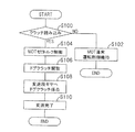
図16は第3実施例に係る電気自動車の制御装置の動作を示すフロー・チャートである。図示のプログラムは同様にAMT/ECU54によって実行される。
FIG. 16 is a flowchart showing the operation of the control apparatus for an electric vehicle according to the third embodiment. The illustrated program is similarly executed by the AMT /
以下説明すると、S100においてクラッチ踏み込み、即ち、運転者によってクラッチペダル64の踏み込みがなされたか否かクラッチぺダルスイッチ66の出力から判断し、否定されるときはS102に進み、モータ通常運転制御、即ち、モータ12の制御としてゼロトルク制御ではない通常の制御を維持し、以降の処理をスキップする。
In the following description, it is judged from the output of the
他方、S100で肯定されるときはS104に進み、第1実施例と同様にMOTゼロトルク制御を実行する。即ち、変速指示がなされたとき、変速段ギヤが切り替えられる前に、モータ12の出力を零あるいはその近傍からなる所定値、具体的にはゼロトルクに制御する。
On the other hand, when the result in S100 is affirmative, the program proceeds to S104, and MOT zero torque control is executed as in the first embodiment. That is, when a gear shift instruction is issued, the output of the
尚、このとき、第2実施例で説明したように、所定値にモータ12の回転子と入力軸16aのフリクショントルクに相当する値を加算し、その値に制御しても良い。
At this time, as described in the second embodiment, a value corresponding to the friction torque of the rotor of the
尚、上記の処理につれて運転者のシフトレバー30の操作に伴ってチェンジ機構16fで選択される変速前のドグクラッチが開放され(S106)、変速先の変速段ギヤ16cにドグクラッチが係合され(S108)、変速完了と判断されて(S110)終了する。
In accordance with the above processing, the dog clutch before the shift selected by the change mechanism 16f is released in accordance with the driver's operation of the shift lever 30 (S106), and the dog clutch is engaged with the
尚、図15に破線で示すようにシフトパターン30bに2個のシフトレバーポジションセンサ32a,32bを配置し、それらセンサの運転者によるシフトレバー30の操作位置を示す出力をAMT/ECU54に入力し、AMT/ECU54において変速がシフトアップかダウンかをアクセル開度などから予測し、S106とS108の間で第1実施例と同様のモータ変速後回転数合わせを実行するようにしても良い。
As shown by broken lines in FIG. 15, two shift
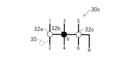
図17は第3実施例の変形例のシフトパターン30cを示す説明図、図18はその動作を示すフロー・チャートである。図示のように変形例の場合、前進6速、後進(R)1速からなるシフトパターン30cを備える。また、シフトパターン30cにおいてN(ニュートラル)ポジションとその両側に計3個のシフトレバーポジションセンサ32a,32b,32cを配置してシフトレバー30の位置を検出するようにした。
FIG. 17 is an explanatory diagram showing a
即ち、変速段を多く有する変形例の場合、複数段を飛ばして変速された場合、モータ12の小さなイナーシャでも差回転の大きさから噛み合い式クラッチ16eを損傷する恐れもあるため、検出されたシフトレバー30のポジションと協調した回転数制御を行うようにした。
That is, in the case of a modified example having a large number of gears, the gear shift clutch 16e may be damaged due to the magnitude of the differential rotation even when the gears are shifted by skipping a plurality of gears. The number of revolutions is controlled in coordination with the position of the
以下説明すると、S200においてクラッチ踏み込みか否かをクラッチペダルスイッチ66の出力から判断し、否定されるときはS202に進み、モータ通常運転制御を維持して以降の処理をスキップする。
Explaining in the following, in S200, it is determined from the output of the
他方、S200で肯定されるときはS204に進んでモータゼロトルク制御を実行し、S206に進んでドグクラッチを中立位置に開放する。 On the other hand, when the result in S200 is affirmative, the routine proceeds to S204, where motor zero torque control is executed, and the routine proceeds to S206, where the dog clutch is released to the neutral position.
次いでS208に進み、第1、第2、第3シフトレバーポジションセンサ32a,32b、32c(以下「第1センサ32a、第2センサ32b、第3センサ32c」という)の出力に基づき、図17に示すシフトパターン30cにおいてシフトレバー30が第2センサ32bの配置位置(Nポジション)に右から到達(第3センサ32cの位置から第2センサ32bの位置へ変化)したか、即ち、5速あるいは6速からのシフトダウンか否か判断する。
Next, in S208, based on the outputs of the first, second, and third shift
尚、図18フロー・チャートの説明において「左」あるいは「右」は全て第2センサ32bの配置位置(Nポジション)を基準とするシフトレバー30の操作方向を意味するため、以降、単に「左」あるいは「右」という。
In the description of the flowchart of FIG. 18, “left” or “right” means the operation direction of the
S208で肯定されるときは5速あるいは6速からのシフトダウンかと判断してS210に進み、モータ12の回転数を4速相当値まで増加し、S212に進み、次に左へ移動(第2センサ32bの位置から第1センサ32aの位置へ変化)したか否か判断し、肯定されるときは2速あるいは1速へのシフトダウンと判断してS214に進み、モータ12の回転数を2速相当まで増加する。S212で否定されるときはS214の処理をスキップする。
When the result in S208 is affirmative, it is determined whether the gear is shifted down from the fifth speed or the sixth speed, and the process proceeds to S210, the number of revolutions of the
尚、上記の運転者のシフトレバー30の操作に応じてチェンジ機構16fで選択される変速先の変速段ギヤ16cの噛合い式クラッチ16eのドグクラッチが係合され(S216)、変速完了と判断されて(S218)終了する。
Note that the dog clutch of the meshing clutch 16e of the
他方、S208で否定されるときは1速あるいは2速からのシフトアップかと判断してS220に進み、左から到達(第1センサ32aの位置から第2センサ32bの位置へ変化)したか否か判断し、肯定されるときはS222に進み、モータ12の回転数を3速相当まで低減する。
On the other hand, when the result in S208 is negative, it is determined that the shift is up from the first speed or the second speed, and the process proceeds to S220, where it is reached from the left (change from the position of the
次いでS224に進み、次に右へ移動(第2センサ32bの位置から第3センサ32cの位置へ変化)したか否か判断し、肯定されるときはS226に進み、モータ12の回転数を5速相当まで低減し、S216以降に進む。尚、S224で否定されるときはS226の処理をスキップする。
Next, the process proceeds to S224, and then it is determined whether or not it has moved to the right (change from the position of the
他方、S220で否定されるときは3速あるいは4速からのシフトかと判断してS228に進み、次に左へ移動(第2センサ32bの位置から第1センサ32aの位置へ変化)したか否か判断し、肯定されるときはS230に進み、モータ12の回転数を2速相当まで低減し、S216以降に進む。
On the other hand, when the result in S220 is negative, it is determined that the shift is from the 3rd speed or the 4th speed, the process proceeds to S228, and then moved to the left (change from the position of the
S228で否定されるときはS232に進み、次に右へ移動(第2センサ32bの位置から第3センサ32cの位置へ変化)したか否か判断し、肯定されるときはS234に進み、モータ12の回転数を5速相当まで低減し、S216以降に進む。尚、S232で否定されるときはS234の処理をスキップする。
When the result in S228 is negative, the process proceeds to S232, and then it is determined whether or not it has moved to the right (change from the position of the
上記した如く、第3実施例に係る電気自動車の制御装置においても、変速指示がなされたとき、変速段ギヤ16cが切り替えられる前に、モータ12の出力を零あるいはその近傍からなる所定値、具体的にはゼロトルクに制御する如く構成したので、第1実施例と同様、変速段ギヤ16cを切り替えるときもモータ12と変速機16を接続するクラッチを不要にでき、よって構成を簡易にできると共に、重量やコストの増加を抑制することができる。
As described above, also in the control apparatus for an electric vehicle according to the third embodiment, when a gear shift instruction is given, the output of the
また、2速から4速へ、あるいは5速から3速へなどと複数段飛ばしで変速された場合も、検出されたシフトレバー30のポジションと協調してモータ12の回転数制御を行うようにしたので、噛み合い式クラッチ16eの損傷を回避することができる。
In addition, when the speed is changed by skipping a plurality of stages, such as from 2nd speed to 4th speed, or from 5th speed to 3rd speed, the rotational speed of the
上記した如く、第1、第2、第3実施例にあっては、車両10に搭載されるモータ(電動機)12と、少なくとも運転者に操作されるアクセルペダル46の開度に応じて前記モータの出力を制御するモータ出力制御手段(MOT/ECU52)と、変速指示がなされたとき、前記モータに接続される入力軸16aと駆動輪20に接続される出力軸16bの間に配置される複数個の変速段ギヤ16cを切り替える噛み合い式クラッチ16eを有する変速機16とを備えた電気自動車の制御装置において、前記モータ出力制御手段は、前記変速指示がなされたとき(S10,S12,S100,S200)、前記噛み合い式クラッチ16eが前記複数個の変速段ギヤを切り替える前に(S20からS26,S106からS110,S206からS234)、前記モータ12の出力を零あるいはその近傍からなる所定値に制御する(S18、S104,S204)ように構成した。
As described above, in the first, second, and third embodiments, the motor (electric motor) 12 mounted on the
また、前記モータ出力制御手段によって前記変速指示がなされたときに前記モータ12の出力を所定値に制御された後、前記噛合い式クラッチ16eを開放し(S18,S20,S104,S106,S204,S206)、前記モータ出力制御手段によって前記入力軸16aと出力軸16bの差回転が所定範囲となるように制御された後(S22,S210,S214,S222,S226,S230,S234)、前記噛み合い式クラッチ16eを係合する(S24,S108,S216)如く構成した。
Further, after the output of the
また、第2実施例にあっては、前記モータ出力制御手段は、前記変速指示がなされたとき、前記モータの出力を、前記所定値に前記モータの回転子と前記入力軸16aのフリクショントルク(付加トルク)に相当する値を加算して得た値に制御する(S18,S104,S204)如く構成した。
In the second embodiment, when the shift instruction is given, the motor output control means sets the output of the motor to the predetermined value as the friction torque (of the rotor of the motor and the
また、第2実施例にあっては、前記モータ出力制御手段は、前記フリクショントルクに相当する値を前記変速機16の油温TATFと前記入力軸16aの回転数に基づいて変更する如く構成した。
Further, in the second embodiment, the motor output control means is configured to change the value corresponding to the friction torque based on the oil temperature TATF of the
また、第1実施例にあっては、前記複数個の変速段ギヤ16cは、前記モータ12の高速側のノイズピークが前記車両10の設定最高車速を超えた領域で発生するように変速比が設定される(図10)如く構成した。
In the first embodiment, the plurality of shift gears 16c have a gear ratio such that a noise peak on the high speed side of the
尚、上記において変速機の例として平行軸方式の変速機を示したが、この発明はそれに限定されるものではなく、その他の形式の変速機であっても良い。 In the above description, the parallel shaft type transmission is shown as an example of the transmission. However, the present invention is not limited to this, and other types of transmissions may be used.
また、第3実施例において最小限の数のシフトポジションセンサを実装してシンクロ機構に負担をかけないように構成したが、シフトポジションセンサの数を増加してそれぞれの変速段ごとに配置して、変速後の回転数合わせをより精緻に行うようにしても良い。 Further, in the third embodiment, the minimum number of shift position sensors is mounted so as not to place a burden on the synchro mechanism, but the number of shift position sensors is increased and arranged for each shift stage. The rotation speed after shifting may be adjusted more precisely.
また、シフトポジションセンサの数を増加してそれぞれの変速段ごとに配置する場合、チェンジ機構16fにシフトアクチュエータを接続すると共に(図示せず)、図15に破線で示すように運転者によるシフトレバー30の操作をAMT/ECU54に入力し、チェンジ機構16fの動作を電気的に制御するようにしても良い。
In addition, when the number of shift position sensors is increased and arranged at each gear position, a shift actuator is connected to the change mechanism 16f (not shown), and a shift lever by the driver as shown by a broken line in FIG. 30 operations may be input to the AMT /
10 車両(電気自動車)、12 モータ(電動機)、16 変速機、16a 入力軸、16b 出力軸、16c 変速段ギヤ、16d シフトアクチュエータ(アクチュエータ)、16e 噛み合い式クラッチ、20 駆動輪、22 PDU、24 バッテリ(BATT)、30 シフトレバー、30a,30b,30c シフトパターン、30a2 サブレンジ、32 シフトレバーポジションセンサ、34 油温センサ、46 アクセルペダル、48 アクセル開度センサ、50 車速センサ、52 MOT/ECU(モータ出力制御手段)、54 AMT/ECU、64 クラッチペダル、66 クラッチペダルスイッチ
DESCRIPTION OF
Claims (5)
Priority Applications (1)
| Application Number | Priority Date | Filing Date | Title |
|---|---|---|---|
| JP2011015572A JP5832094B2 (en) | 2011-01-27 | 2011-01-27 | Electric vehicle control device |
Applications Claiming Priority (1)
| Application Number | Priority Date | Filing Date | Title |
|---|---|---|---|
| JP2011015572A JP5832094B2 (en) | 2011-01-27 | 2011-01-27 | Electric vehicle control device |
Publications (2)
| Publication Number | Publication Date |
|---|---|
| JP2012157199A true JP2012157199A (en) | 2012-08-16 |
| JP5832094B2 JP5832094B2 (en) | 2015-12-16 |
Family
ID=46838307
Family Applications (1)
| Application Number | Title | Priority Date | Filing Date |
|---|---|---|---|
| JP2011015572A Active JP5832094B2 (en) | 2011-01-27 | 2011-01-27 | Electric vehicle control device |
Country Status (1)
| Country | Link |
|---|---|
| JP (1) | JP5832094B2 (en) |
Cited By (3)
| Publication number | Priority date | Publication date | Assignee | Title |
|---|---|---|---|---|
| WO2014084102A1 (en) * | 2012-11-29 | 2014-06-05 | ダイムラー・アクチェンゲゼルシャフト | Speed change controller for electric vehicle |
| JP2015149876A (en) * | 2014-02-10 | 2015-08-20 | 本田技研工業株式会社 | Power transmission device of electrically-powered apparatus |
| JP2022036845A (en) * | 2020-08-24 | 2022-03-08 | トヨタ自動車株式会社 | Control device for electric vehicle |
Citations (6)
| Publication number | Priority date | Publication date | Assignee | Title |
|---|---|---|---|---|
| JPH09205703A (en) * | 1996-01-26 | 1997-08-05 | Seiko Epson Corp | Drive device for electric car and control method therefor |
| JP2000295709A (en) * | 1999-04-06 | 2000-10-20 | Toyota Motor Corp | Speed change time control equipment of electric automobile |
| JP2005282741A (en) * | 2004-03-30 | 2005-10-13 | Mitsubishi Fuso Truck & Bus Corp | Control device for hybrid automobile |
| JP2006231977A (en) * | 2005-02-22 | 2006-09-07 | Toyota Motor Corp | Control device and control method for vehicle |
| JP2010031980A (en) * | 2008-07-30 | 2010-02-12 | Nissan Motor Co Ltd | Gradient estimating device |
| JP2012157200A (en) * | 2011-01-27 | 2012-08-16 | Honda Motor Co Ltd | Control device of electric vehicle |
-
2011
- 2011-01-27 JP JP2011015572A patent/JP5832094B2/en active Active
Patent Citations (6)
| Publication number | Priority date | Publication date | Assignee | Title |
|---|---|---|---|---|
| JPH09205703A (en) * | 1996-01-26 | 1997-08-05 | Seiko Epson Corp | Drive device for electric car and control method therefor |
| JP2000295709A (en) * | 1999-04-06 | 2000-10-20 | Toyota Motor Corp | Speed change time control equipment of electric automobile |
| JP2005282741A (en) * | 2004-03-30 | 2005-10-13 | Mitsubishi Fuso Truck & Bus Corp | Control device for hybrid automobile |
| JP2006231977A (en) * | 2005-02-22 | 2006-09-07 | Toyota Motor Corp | Control device and control method for vehicle |
| JP2010031980A (en) * | 2008-07-30 | 2010-02-12 | Nissan Motor Co Ltd | Gradient estimating device |
| JP2012157200A (en) * | 2011-01-27 | 2012-08-16 | Honda Motor Co Ltd | Control device of electric vehicle |
Cited By (5)
| Publication number | Priority date | Publication date | Assignee | Title |
|---|---|---|---|---|
| WO2014084102A1 (en) * | 2012-11-29 | 2014-06-05 | ダイムラー・アクチェンゲゼルシャフト | Speed change controller for electric vehicle |
| JP2014108011A (en) * | 2012-11-29 | 2014-06-09 | Daimler Ag | Shift control device of electric automobile |
| JP2015149876A (en) * | 2014-02-10 | 2015-08-20 | 本田技研工業株式会社 | Power transmission device of electrically-powered apparatus |
| JP2022036845A (en) * | 2020-08-24 | 2022-03-08 | トヨタ自動車株式会社 | Control device for electric vehicle |
| JP7413957B2 (en) | 2020-08-24 | 2024-01-16 | トヨタ自動車株式会社 | Electric vehicle control device |
Also Published As
| Publication number | Publication date |
|---|---|
| JP5832094B2 (en) | 2015-12-16 |
Similar Documents
| Publication | Publication Date | Title |
|---|---|---|
| JP3208866B2 (en) | Drive for electric vehicles | |
| JP3988428B2 (en) | Automatic transmissions, control devices, and automobiles | |
| US7967721B2 (en) | Control apparatus for an automatic transmission | |
| GB2289774A (en) | Drive control system for battery car | |
| JP4720549B2 (en) | Vehicle control device | |
| CN104802789A (en) | Method and apparatus for controlling a torque converter clutch in a multi-mode powertrain system | |
| JP5832094B2 (en) | Electric vehicle control device | |
| JP6157829B2 (en) | Electric vehicle rollback suppression control device | |
| JP2012157200A (en) | Control device of electric vehicle | |
| JP2012175769A (en) | Electric vehicle | |
| JP2007181289A (en) | Controller for four-wheel-drive vehicle | |
| JP3807369B2 (en) | Hybrid vehicle | |
| JP5570299B2 (en) | Hybrid vehicle | |
| JP2013152001A (en) | Shift control method and shift control device of electric vehicle | |
| JP5359937B2 (en) | Hybrid vehicle | |
| JP3746507B2 (en) | Electric vehicle drive control device | |
| JP6447154B2 (en) | Vehicle drive device | |
| US10471949B2 (en) | Automobile equipped with three-phase motor | |
| JP4358149B2 (en) | Power transmission device for hybrid vehicle | |
| US11186284B2 (en) | Control device | |
| JP3692796B2 (en) | Hybrid vehicle | |
| JP4432314B2 (en) | Brake device mounted on a vehicle | |
| JP2009154865A (en) | Braking device mounted on vehicle | |
| JP5394187B2 (en) | vehicle | |
| JP4529798B2 (en) | Rotation information calculation device for transmission mechanism |
Legal Events
| Date | Code | Title | Description |
|---|---|---|---|
| A621 | Written request for application examination |
Free format text: JAPANESE INTERMEDIATE CODE: A621 Effective date: 20131128 |
|
| A131 | Notification of reasons for refusal |
Free format text: JAPANESE INTERMEDIATE CODE: A131 Effective date: 20140827 |
|
| A977 | Report on retrieval |
Free format text: JAPANESE INTERMEDIATE CODE: A971007 Effective date: 20140827 |
|
| A131 | Notification of reasons for refusal |
Free format text: JAPANESE INTERMEDIATE CODE: A131 Effective date: 20150520 |
|
| A521 | Written amendment |
Free format text: JAPANESE INTERMEDIATE CODE: A523 Effective date: 20150709 |
|
| TRDD | Decision of grant or rejection written | ||
| A01 | Written decision to grant a patent or to grant a registration (utility model) |
Free format text: JAPANESE INTERMEDIATE CODE: A01 Effective date: 20151006 |
|
| A61 | First payment of annual fees (during grant procedure) |
Free format text: JAPANESE INTERMEDIATE CODE: A61 Effective date: 20151027 |
|
| R150 | Certificate of patent or registration of utility model |
Ref document number: 5832094 Country of ref document: JP Free format text: JAPANESE INTERMEDIATE CODE: R150 |
|
| R250 | Receipt of annual fees |
Free format text: JAPANESE INTERMEDIATE CODE: R250 |