JP2012154392A - Controller for automatic transmission - Google Patents
Controller for automatic transmission Download PDFInfo
- Publication number
- JP2012154392A JP2012154392A JP2011013185A JP2011013185A JP2012154392A JP 2012154392 A JP2012154392 A JP 2012154392A JP 2011013185 A JP2011013185 A JP 2011013185A JP 2011013185 A JP2011013185 A JP 2011013185A JP 2012154392 A JP2012154392 A JP 2012154392A
- Authority
- JP
- Japan
- Prior art keywords
- oil
- oil passage
- pump
- electric
- engine
- Prior art date
- Legal status (The legal status is an assumption and is not a legal conclusion. Google has not performed a legal analysis and makes no representation as to the accuracy of the status listed.)
- Pending
Links
Images
Landscapes
- Control Of Transmission Device (AREA)
Abstract
【課題】アイドルストップ制御によるエンジン停止時に摩擦要素へのオイルの供給源を機械式オイルポンプから電動式オイルポンプに切り換える際に、エネルギー損失を少なくしつつ摩擦要素へ供給される油圧が一時的に低下することを抑制するようにする。
【解決手段】アイドルストップ手段を備えた自動変速機の制御装置は、機械式オイルポンプから導かれた第1油路と電動式オイルポンプから導かれた第2油路を摩擦要素に通じる第3油路に選択的に接続し、アイドルストップ手段によるエンジンの自動停止時に、第1油路が第3油路に接続された状態から第2油路が第3油路に接続された状態に切り換える油路切換手段を備え、電動式オイルポンプの駆動を制御するポンプ駆動制御手段は、第1油路が第3油路に接続された状態から第2油路が第3油路に接続された状態に切り換えられる前に電動式オイルポンプの駆動を開始するように制御する。
【選択図】図5The hydraulic pressure supplied to a friction element is temporarily reduced while reducing energy loss when the oil supply source to the friction element is switched from a mechanical oil pump to an electric oil pump when the engine is stopped by idle stop control. Try to suppress the decline.
A control device for an automatic transmission having an idle stop means includes a first oil path led from a mechanical oil pump and a second oil path led from an electric oil pump to a friction element. Selectively connected to the oil passage, and when the engine is automatically stopped by the idle stop means, the state in which the first oil passage is connected to the third oil passage is switched to the state in which the second oil passage is connected to the third oil passage. The pump drive control means that includes an oil passage switching means and controls the driving of the electric oil pump is configured such that the second oil passage is connected to the third oil passage from the state where the first oil passage is connected to the third oil passage. It is controlled to start driving the electric oil pump before switching to the state.
[Selection] Figure 5
Description
本発明は、自動車等の車両に搭載される自動変速機の制御装置に関し、特にアイドルストップ制御を行う車両に搭載される自動変速機の制御装置に関する。 The present invention relates to a control device for an automatic transmission mounted on a vehicle such as an automobile, and more particularly to a control device for an automatic transmission mounted on a vehicle that performs idle stop control.
自動車等の車両に搭載される自動変速機として、エンジン出力軸に取り付けられたトルクコンバータと、該トルクコンバータの出力側に連結されると共にクラッチ及びブレーキ等の複数の摩擦要素を備えた変速機構と、エンジン駆動による機械式オイルポンプとを有し、機械式のオイルポンプから供給されるオイルによって複数の摩擦要素を選択的に締結して減速比の異なる複数の変速段を達成するようにしたものが一般に知られている。 As an automatic transmission mounted on a vehicle such as an automobile, a torque converter attached to an engine output shaft, and a transmission mechanism connected to the output side of the torque converter and provided with a plurality of friction elements such as clutches and brakes , Having a mechanical oil pump driven by an engine, and selectively engaging a plurality of friction elements with oil supplied from the mechanical oil pump to achieve a plurality of speed stages with different reduction ratios Is generally known.
また、近年では、自動変速機が搭載された車両において、交差点等における停車時に、所定の停止条件の成立によりエンジンを自動停止させると共に、所定の再始動条件の成立によりエンジンを自動再始動させる所謂アイドルストップ制御を行うようにしたものも一般に知られている。 In recent years, in vehicles equipped with an automatic transmission, when stopping at an intersection or the like, the engine is automatically stopped when a predetermined stop condition is satisfied, and the engine is automatically restarted when a predetermined restart condition is satisfied. A device that performs idle stop control is also generally known.
しかしながら、自動変速機が搭載された車両でアイドルストップ制御を実施する場合、エンジン停止時に、機械式オイルポンプも停止するので、停車直前に締結されていた摩擦要素、換言すれば発進時に動力を伝達する摩擦要素が一旦解放され、その後、エンジン再始動時に再び締結されることになり、その際、締結の応答遅れによる発進性の悪化や、締結に伴うショックの問題が発生することとなる。 However, when performing idle stop control on a vehicle equipped with an automatic transmission, the mechanical oil pump is also stopped when the engine is stopped, so that the friction element that was fastened immediately before stopping, in other words, power is transmitted when starting. The friction element to be released is once released and then re-engaged when the engine is restarted. At this time, the startability is deteriorated due to the delayed response of the engagement, and the problem of shock due to the engagement occurs.
これに対しては、特許文献1に開示されているように、エンジンからの動力により駆動される機械式オイルポンプとは別に、電動機からの動力により駆動される電動式オイルポンプを備え、該電動式オイルポンプからのオイルにより、エンジン停止中も摩擦要素を締結させた状態に維持することが行なわれる。これによれば、エンジン再始動時における摩擦要素の締結の応答遅れによる発進性の悪化や、摩擦要素の締結時のショックの発生を抑制することができる。 For this, as disclosed in Patent Document 1, an electric oil pump driven by power from an electric motor is provided separately from a mechanical oil pump driven by power from an engine. The oil from the oil pump is used to keep the friction element fastened even when the engine is stopped. According to this, it is possible to suppress the deterioration of the startability due to the response delay of the engagement of the friction element when the engine is restarted and the occurrence of a shock when the friction element is engaged.
しかしながら、エンジン駆動による機械式オイルポンプとは別に電動式オイルポンプを備え、該電動式オイルポンプからのオイルによってエンジン停止中も摩擦要素を締結するようにする場合に、電動式オイルポンプを絶えず駆動させていると、エネルギー損失が大きくなることとなる。 However, when the electric oil pump is provided separately from the mechanical oil pump driven by the engine and the friction element is fastened even when the engine is stopped by the oil from the electric oil pump, the electric oil pump is continuously driven. If this is done, energy loss will increase.
これに対して、自動変速機の摩擦要素へのオイルの供給源が機械式オイルポンプから電動式オイルポンプに切り換える制御が行われた後に、電動式オイルポンプの駆動を開始すると、エネルギー損失を少なくすることができるものの、摩擦要素へ供給される油圧が一時的に低下することとなる。この場合、特に停車直後にエンジン再始動条件が成立して摩擦要素を再び締結する際に、締結の応答遅れによる発進性の悪化や、締結時のショックの問題が生じることとなる。 On the other hand, when the drive of the electric oil pump is started after the control of switching the oil supply source to the friction element of the automatic transmission from the mechanical oil pump to the electric oil pump, energy loss is reduced. However, the hydraulic pressure supplied to the friction element is temporarily reduced. In this case, particularly when the engine restart condition is satisfied immediately after the vehicle stops and the friction element is reengaged, the startability is deteriorated due to the delayed response of engagement, and the problem of shock at the time of engagement occurs.
そこで、本発明は、エンジン駆動による機械式オイルポンプとは別に電動式オイルポンプを備え、アイドルストップ制御によるエンジン停止中に電動式オイルポンプからのオイルにより摩擦要素を締結するようにするようにした自動変速機において、エネルギー損失を少なくしつつ摩擦要素へ供給される油圧が一時的に低下することを抑制することができる自動変速機の制御装置を提供することを目的とする。 Therefore, the present invention is provided with an electric oil pump separately from the mechanical oil pump driven by the engine, and the friction element is fastened by the oil from the electric oil pump while the engine is stopped by the idle stop control. An object of the present invention is to provide an automatic transmission control device capable of suppressing a temporary decrease in hydraulic pressure supplied to a friction element while reducing energy loss in an automatic transmission.
このため、本願の請求項1に係る発明は、摩擦要素にオイルを供給するエンジン駆動の機械式オイルポンプと、前記摩擦要素にオイルを供給する電動式オイルポンプと、該電動式オイルポンプの駆動を制御するポンプ駆動制御手段とを備えると共に、車両の停車時において所定のエンジン停止条件が成立したときにエンジンを自動停止すると共に、この自動停止状態で所定のエンジン再始動条件が成立したときに、エンジンを自動再始動させるアイドルストップ手段を備えた自動変速機の制御装置であって、前記機械式オイルポンプから導かれた第1油路と前記電動式オイルポンプから導かれた第2油路を前進発進段で締結される摩擦要素に通じる第3油路に選択的に接続し、前記アイドルストップ手段によるエンジンの自動停止時に、前記第1油路が第3油路に接続された状態から前記第2油路が第3油路に接続された状態に切り換える油路切換手段を備え、前記ポンプ駆動制御手段は、前記油路切換手段によって前記第1油路が第3油路に接続された状態から前記第2油路が第3油路に接続された状態に切り換えられる前に前記電動式オイルポンプの駆動を開始するように前記電動式オイルポンプの駆動を制御する、ことを特徴とする。 Therefore, the invention according to claim 1 of the present application is directed to an engine-driven mechanical oil pump that supplies oil to the friction element, an electric oil pump that supplies oil to the friction element, and driving of the electric oil pump. And a pump drive control means for controlling the engine, and when the predetermined engine stop condition is satisfied when the vehicle is stopped, the engine is automatically stopped, and when the predetermined engine restart condition is satisfied in the automatic stop state. A control device for an automatic transmission having an idle stop means for automatically restarting the engine, wherein the first oil path led from the mechanical oil pump and the second oil path led from the electric oil pump Is selectively connected to a third oil passage leading to a friction element fastened at the forward start stage, and when the engine is automatically stopped by the idle stop means, Oil path switching means for switching from a state in which one oil path is connected to the third oil path to a state in which the second oil path is connected to the third oil path is provided, and the pump drive control means includes the oil path switching means. So as to start driving the electric oil pump before the second oil passage is connected to the third oil passage from the state where the first oil passage is connected to the third oil passage. The drive of the electric oil pump is controlled.
また、本願の請求項2に係る発明は、請求項1に係る発明において、前記油路切換手段は、前記第1油路の油圧が所定圧以上である場合に前記第1油路を第3油路に接続し、前記第1油路の油圧が所定圧未満である場合に前記第2油路を第3油路に接続するものであり、前記第1油路の油圧を検出する油圧検出手段と、該油圧検出手段によって検出される前記第1油路の油圧に基づいて、前記油路切換手段によって前記第1油路が第3油路に接続された状態から前記第2油路が第3油路に接続された状態に切り換えられる切換タイミングを予測する切換タイミング予測手段と、をさらに備え、前記ポンプ駆動制御手段は、前記切換タイミング予測手段によって予測される前記切換タイミングに基づいて、前記電動式オイルポンプの駆動を開始するように前記電動式オイルポンプの駆動を制御する、ことを特徴とする。 In the invention according to claim 2 of the present application, in the invention according to claim 1, the oil passage switching means is configured such that the first oil passage is third when the oil pressure of the first oil passage is equal to or higher than a predetermined pressure. Oil pressure detection for detecting the oil pressure of the first oil passage, which is connected to the oil passage and connects the second oil passage to the third oil passage when the oil pressure of the first oil passage is less than a predetermined pressure. And the second oil passage from the state in which the first oil passage is connected to the third oil passage by the oil passage switching means based on the oil pressure of the first oil passage detected by the oil pressure detecting means. Switching timing prediction means for predicting switching timing to be switched to the state connected to the third oil passage, the pump drive control means based on the switching timing predicted by the switching timing prediction means, Start driving the electric oil pump It said controlling the driving of the electric oil pump so that, characterized in that.
更に、本願の請求項3に係る発明は、請求項1又は請求項2に係る発明において、前記摩擦要素に供給されるオイルの温度を検出する油温検出手段をさらに備え、前記切換タイミング予測手段は、前記油温検出手段によって検出されるオイルの温度が高い場合には該オイルの温度が低い場合に比して前記切換タイミングが早くなるように前記切換タイミングを予測する、ことを特徴とする。 Further, the invention according to claim 3 of the present application is the invention according to claim 1 or 2, further comprising oil temperature detecting means for detecting the temperature of oil supplied to the friction element, wherein the switching timing predicting means. Is characterized in that when the oil temperature detected by the oil temperature detection means is high, the switching timing is predicted so that the switching timing is earlier than when the oil temperature is low. .
また更に、本願の請求項4に係る発明は、請求項1に係る発明において、ドライバによる減速要求を検出する減速要求検出手段と、車両の車速を検出する車速検出手段と、
をさらに備え、前記ポンプ駆動制御手段は、前記減速要求検出手段によって検出される前記減速要求が大きくなるにつれて、前記車速検出手段によって検出される車速が高い車速で、前記電動式オイルポンプの駆動を開始するように前記電動式オイルポンプの駆動を制御する、ことを特徴とする。
Further, the invention according to claim 4 of the present application is the invention according to claim 1, wherein the deceleration request detecting means for detecting the deceleration request by the driver, the vehicle speed detecting means for detecting the vehicle speed,
The pump drive control means drives the electric oil pump at a higher vehicle speed detected by the vehicle speed detection means as the deceleration request detected by the deceleration request detection means becomes larger. The driving of the electric oil pump is controlled to start.
また更に、本願の請求項5に係る発明は、請求項1から請求項4の何れか1項に係る発明において、前記第2油路に接続され、前記電動式オイルポンプの駆動停止時に前記第2油路の油圧を低下させるための第4油路が設けられ、該第4油路にオリフィスが設けられている、ことを特徴とする。
Still further, the invention according to
また更に、本願の請求項6に係る発明は、請求項1から請求項5の何れか1項に係る発明において、前記電動式オイルポンプは、前記機械式オイルポンプに比して最大容量が小さく設定されたものである、ことを特徴とする。 Still further, the invention according to claim 6 of the present application is the invention according to any one of claims 1 to 5, wherein the electric oil pump has a smaller maximum capacity than the mechanical oil pump. It is characterized by being set.
本願の請求項1に係る自動変速機の制御装置によれば、機械式オイルポンプから導かれた第1油路と電動式オイルポンプから導かれた第2油路を前進発進段で締結される摩擦要素に通じる第3油路に選択的に接続し、アイドルストップ手段によるエンジンの自動停止時に、第1油路が第3油路に接続された状態から第2油路が第3油路に接続された状態に切り換える油路切換手段を備え、ポンプ駆動制御手段は、油路切換手段によって第1油路が第3油路に接続された状態から第2油路が第3油路に接続された状態に切り換えられる前に電動式オイルポンプの駆動を開始するように電動式オイルポンプの駆動を制御する。 According to the control apparatus for an automatic transmission according to claim 1 of the present application, the first oil passage led from the mechanical oil pump and the second oil passage led from the electric oil pump are fastened at the forward start stage. When the engine is automatically stopped by the idle stop means, the second oil passage is changed from the state in which the first oil passage is connected to the third oil passage to the third oil passage. Oil path switching means for switching to a connected state is provided, and the pump drive control means connects the second oil path to the third oil path from the state in which the first oil path is connected to the third oil path by the oil path switching means. The drive of the electric oil pump is controlled so that the drive of the electric oil pump is started before switching to the state.
これにより、エンジンの自動停止時に、摩擦要素へのオイルの供給源が機械式オイルポンプから電動式オイルポンプに切り換えられる前に電動式オイルポンプの駆動を開始して第2油路の油圧を予め高めておくことができるので、電動式オイルポンプを絶えず駆動させている場合に比してエネルギー損失を少なくしつつ摩擦要素へ供給される油圧が一時的に低下することを抑制することができる。従って、エンジン再始動時における摩擦要素の締結の応答遅れによる発進性の悪化や、該摩擦要素の締結時のショックの発生を抑制することができる。 Thus, when the engine is automatically stopped, the drive of the electric oil pump is started before the oil supply source to the friction element is switched from the mechanical oil pump to the electric oil pump, and the hydraulic pressure of the second oil passage is set in advance. Since it can be increased, it is possible to suppress a temporary decrease in the hydraulic pressure supplied to the friction element while reducing energy loss as compared with the case where the electric oil pump is continuously driven. Therefore, it is possible to suppress the deterioration of the startability due to the response delay of the engagement of the friction element when the engine is restarted and the occurrence of a shock when the friction element is engaged.
また、本願の請求項2に係る発明によれば、第1油路の油圧を検出する油圧検出手段と、該油圧検出手段によって検出される第1油路の油圧に基づいて、油路切換手段によって第1油路が第3油路に接続された状態から第2油路が第3油路に接続された状態に切り換えられる切換タイミングを予測する切換タイミング予測手段とをさらに備え、ポンプ駆動制御手段は、予測される切換タイミングに基づいて、電動式オイルポンプの駆動を開始するように電動式オイルポンプの駆動を制御することにより、電動式オイルポンプの駆動開始を第1油路が第3油路に接続された状態から第2油路が第3油路に接続された状態に切り換えられる切換タイミングに基づいて好適に設定することができ、前記効果をより有効に奏することができる。 According to the invention of claim 2 of the present application, the oil pressure switching means for detecting the oil pressure of the first oil path, and the oil path switching means based on the oil pressure of the first oil path detected by the oil pressure detection means. And a switching timing prediction means for predicting a switching timing at which the first oil passage is connected to the third oil passage from the state in which the first oil passage is connected to the state in which the second oil passage is connected to the third oil passage. The means controls the drive of the electric oil pump so as to start the drive of the electric oil pump based on the predicted switching timing, whereby the first oil passage starts the drive of the electric oil pump. It can be suitably set based on the switching timing at which the second oil passage is switched to the state connected to the third oil passage from the state connected to the oil passage, and the effect can be more effectively achieved.
更に、本願の請求項3に係る発明によれば、摩擦要素に供給されるオイルの温度を検出する油温検出手段をさらに備え、切換タイミング予測手段は、油温検出手段によって検出されるオイルの温度が高い場合には該オイルの温度が低い場合に比して切換タイミングが早くなるように切換タイミングを予測することにより、オイルの温度に基づいて変化するオイルの粘性を考慮することにより、切換タイミングの予測精度を向上させることができ、前記効果をより有効に奏することができる。 Further, according to the invention according to claim 3 of the present application, the oil temperature detecting means for detecting the temperature of the oil supplied to the friction element is further provided, and the switching timing predicting means is configured to detect the oil detected by the oil temperature detecting means. When the temperature is high, the switching timing is predicted so that the switching timing is earlier than when the oil temperature is low, and the viscosity of the oil that changes based on the oil temperature is taken into account. Timing prediction accuracy can be improved, and the above-described effect can be more effectively achieved.
また更に、本願の請求項4に係る発明によれば、ドライバによる減速要求を検出する減速要求検出手段と、車両の車速を検出する車速検出手段とをさらに備え、ポンプ駆動制御手段は、減速要求検出手段によって検出される減速要求が大きくなるにつれて、車速が高い車速で、電動式オイルポンプの駆動を開始するように電動式オイルポンプの駆動を制御することにより、第2油路の油圧が高められる前に摩擦要素へのオイルの供給源が機械式オイルポンプから電動式オイルポンプに切り換えられることを抑制することができる。 Furthermore, according to the invention according to claim 4 of the present application, the vehicle further includes a deceleration request detection unit that detects a deceleration request by the driver, and a vehicle speed detection unit that detects a vehicle speed of the vehicle, and the pump drive control unit includes the deceleration request. As the deceleration request detected by the detection means increases, the hydraulic pressure of the second oil passage increases by controlling the drive of the electric oil pump so that the drive of the electric oil pump is started at a higher vehicle speed. It is possible to prevent the oil supply source to the friction element from being switched from the mechanical oil pump to the electric oil pump before being operated.
また更に、本願の請求項5に係る発明によれば、第2油路に接続され、電動式オイルポンプの駆動停止時に第2油路の油圧を低下させるための第4油路が設けられ、該第4油路にオリフィスが設けられていることにより、電動式オイルポンプの駆動停止時に該電動式オイルポンプにかかる圧力を低下させることができ、電動式オイルポンプの信頼性が低下することを抑制することができる。
Furthermore, according to the invention according to
また更に、本願の請求項6に係る発明によれば、電動式オイルポンプは、機械式オイルポンプに比して最大容量が小さく設定されたものであることにより、最大容量が小さく設定された電動式オイルポンプを用いて、前記効果を具体的に実現することができる。最大容量が小さい電動式オイルポンプは、電力の消費が少なく、またサイズや重量も小さいことから、省電力化、レイアウト性の向上及び重量の増加抑制に資することができる。 Still further, according to the invention of claim 6 of the present application, the electric oil pump is set to have a maximum capacity smaller than that of the mechanical oil pump. The above-described effect can be specifically realized by using an oil pump. An electric oil pump having a small maximum capacity consumes less power and is small in size and weight, and thus can contribute to power saving, layout improvement, and weight suppression.
以下、本発明の実施の形態について説明する。 Embodiments of the present invention will be described below.
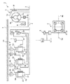
まず、本発明の実施の形態に係るアイドルストップ制御が行われる車両に搭載される自動変速機について説明すると、図1に骨子を示すように、この自動変速機1は、フロントエンジンフロントドライブ車等のエンジン横置き式車両に適用されるもので、主たる構成要素として、エンジン出力軸2に取り付けられたトルクコンバータ3と、該トルクコンバータ3からの動力が入力軸4を介して入力される第1クラッチ10及び第2クラッチ20と、これらのクラッチ10、20や入力軸4から動力が入力される変速機構30とを有し、これらが入力軸4の軸心上に配置されて、変速機ケース5に収納されている。
First, an automatic transmission mounted on a vehicle on which idle stop control is performed according to an embodiment of the present invention will be described. As shown in FIG. 1, the automatic transmission 1 includes a front engine front drive vehicle and the like. As a main component, a torque converter 3 attached to the engine output shaft 2 and power from the torque converter 3 are input through the input shaft 4 as a first component. The clutch 10 and the second clutch 20, and a
また、トルクコンバータ3と第1、第2クラッチ10、20との間には、該トルクコンバータ3を介してエンジンにより駆動される機械式のオイルポンプ6が配置され、また、第1、第2クラッチ10、20と変速機構30との間には、該変速機構30からの動力を取り出す出力ギヤ7が配置されている。そして、該出力ギヤ7から取り出された動力が、カウンタドライブ機構8を介して差動装置9に伝達され、車軸9a、9bを介して前輪を駆動するようになっている。
A mechanical oil pump 6 driven by the engine via the torque converter 3 is disposed between the torque converter 3 and the first and
トルクコンバータ3は、エンジン出力軸2に連結されたケース3aと、該ケース3a内に固設されたポンプ3bと、該ポンプ3bに対向配置されて該ポンプ3bによりオイルを介して駆動されるタービン3cと、該ポンプ3bとタービン3cとの間に介設され、かつ、変速機ケース5にワンウェイクラッチ3dを介して支持されてトルク増大作用を行うステータ3eと、ケース3aとタービン3cとの間に設けられ、該ケース3aを介してエンジン出力軸2とタービン3cとを直結するロックアップクラッチ3fとで構成されている。そして、タービン3cの回転が入力軸4を介して第1、第2クラッチ10、20や変速機構30側に伝達されるようになっている。
The torque converter 3 includes a
また、変速機構30は、第1、第2、第3プラネタリギヤセット(以下「第1、第2、第3ギヤセット」という)40、50、60を有し、これらが変速機ケース5内にトルクコンバータ3側からこの順序で配置されている。
The
また、摩擦要素として、第1、第2クラッチ10、20の他に、変速機構30を構成する第1ブレーキ70、第2ブレーキ80及び第3ブレーキ90が備えられ、エンジン側からこの順序で配置されている。また、第1ブレーキ70に並列にワンウェイクラッチ71が配置されている。
In addition to the first and
第1、第2、第3ギヤセット40、50、60は、いずれもシングルピニオン型のプラネタリギヤセットであって、サンギヤ41、51、61と、これらのサンギヤ41、51、61にそれぞれ噛み合った各複数のピニオン42、52、62と、これらのピニオン42、52、62をそれぞれ支持するキャリヤ43、53、63と、各複数のピニオン42、52、62にそれぞれ噛み合ったリングギヤ44、54、64とで構成されている。
The first, second, and third gear sets 40, 50, and 60 are all single-pinion type planetary gear sets, and each of the sun gears 41, 51, and 61 is engaged with the sun gears 41, 51, and 61, respectively.
そして、入力軸4が第3ギヤセット60のサンギヤ61に連結されていると共に、第1ギヤセット40のサンギヤ41と第2ギヤセット50のサンギヤ51、第1ギヤセット40のリングギヤ44と第2ギヤセット50のキャリヤ53、第2ギヤセット50のリングギヤ54と第3ギヤセット60のキャリヤ63が、それぞれ連結されている。そして、第1ギヤセット40のキャリヤ43に出力ギヤ7が連結されている。
The input shaft 4 is connected to the
また、第1ギヤセット40のサンギヤ41及び第2ギヤセット50のサンギヤ51は、第1クラッチ10の出力部材11に連結され、該第1クラッチ10を介して入力軸4に断接可能に連結されている。また、第1ギヤセット40のリングギヤ44及び第2ギヤセット50のキャリヤ53は、第2クラッチ20の出力部材21に連結され、該第2クラッチ20を介して入力軸4に断接可能に連結されている。
The sun gear 41 of the first gear set 40 and the
さらに、第1ギヤセット40のリングギヤ44及び第2ギヤセット50のキャリヤ53は、並列に配置された第1ブレーキ70及びワンウェイクラッチ71を介して変速機ケース5に断接可能に連結されており、第2ギヤセット50のリングギヤ54及び第3ギヤセット60のキャリヤ63は、第2ブレーキ80を介して変速機ケース5に断接可能に連結されており、さらに、第3ギヤセット60のリングギヤ64は、第3ブレーキ90を介して変速機ケース5に断接可能に連結されている。
Further, the ring gear 44 of the first gear set 40 and the
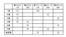
以上の構成により、この自動変速機1によれば、第1、第2クラッチ10、20及び第1、第2、第3ブレーキ70、80、90の締結状態の組み合わせにより、前進6速と後退速とが得られるようになっており、その組み合わせと変速段の関係を図2の締結表に示す。
With the above configuration, according to the automatic transmission 1, the sixth forward speed and the reverse speed are achieved by combining the engagement states of the first and
ここで、第1ブレーキ70は、エンジンブレーキ作動用のレンジで締結されるようになっており、Dレンジ等では、該第1ブレーキ70に代えてワンウェイクラッチ71がロックすることにより1速段が実現されるようになっているが、Dレンジ等の1速で第1ブレーキ70を締結する場合もある。
Here, the
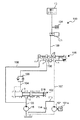
以上のような各クラッチ10、20及びブレーキ70、80、90の締結、解放は油圧制御回路によって制御されるようになっており、該油圧制御回路100のうち、停車直前及び発進時の変速段である1速を実現する部分は、図3に示すように構成されている。
Engagement and disengagement of the
即ち、この油圧制御回路100は、エンジンによって駆動される機械式のオイルポンプ(以下「機械ポンプ」という)6とは別に設けられたモータ101aによって駆動される電動式のオイルポンプ(以下「電動ポンプ」という)101を有すると共に、機械ポンプ6の吐出側には、レンジ位置に応じて該ポンプ6からの油圧を各摩擦要素に振り分けて供給するマニュアルバルブ102が配置されている。
That is, the
このマニュアルバルブ102は、ライン103を介して機械ポンプ6に接続された入力ポートaと、Dレンジ等の前進走行レンジで該入力ポートaに連通する前進用出力ポートbとを有し、Nレンジでは、入力ポートaはいずれの出力用ポートbにも連通せず、該出力ポートbはドレンされるようになっている。
The
前進用出力ポートbに接続された前進用ライン104は、オリフィスとチェックバルブとで構成されてオイルの排出方向に絞り作用を有する一方向絞り機構105を介して油路切換手段としてのオイルポンプシフトバルブ(以下「シフトバルブ」という)106に導かれ、該シフトバルブ106の第1入力ポートdに接続されている。
The
また、このシフトバルブ106の第2入力ポートeには、ライン107を介して電動ポンプ101の吐出側が接続されていると共に、該シフトバルブ106の一端の制御ポートfには、機械ポンプ6の吐出側のライン103から分岐されたライン108が接続されている。
The discharge port of the
シフトバルブ106は、その内部で移動可能なスプール130を有し、該スプール130の移動により、ライン104を第1クラッチ10に連通させる第1状態と、ライン107を第1クラッチ10に連通させる第2状態とに切り換えられるようになっている。具体的に、シフトバルブ106は、ライン104を第1クラッチ10に連通させる第1位置(図の下半部で示す右側の位置)にスプール130が位置するとき第1状態となり、ライン107を第1クラッチ10に連通させる第2位置(図の上半部で示す左側の位置)にスプール130が位置するとき第2状態となるように構成されている。
The
そして、機械ポンプ6の作動時に、該ポンプ6の吐出圧がライン108を介してシフトバルブ106の制御ポートfに導入され、該導入された油圧が所定圧以上になるとき、スプリングの付勢力に抗してスプール130が第1位置に移動し、これにより、第1入力ポートdがシフトバルブ106の出力ポートgに連通する。
When the mechanical pump 6 is operated, the discharge pressure of the pump 6 is introduced into the control port f of the
また、機械ポンプ6の非作動時は、制御ポートfに該ポンプ6の吐出圧が導入されないので、スプリングの付勢力によってスプール130が第2位置に移動し、このとき、第2入力ポートeが出力ポートgに連通する。
Further, when the mechanical pump 6 is not in operation, the discharge pressure of the pump 6 is not introduced into the control port f, so that the
そして、このシフトバルブ106の出力ポートgは、ライン109に接続されており、該ライン109が、油圧制御用のリニアソレノイドバルブ121を介して第1クラッチ10に導かれている。リニアソレノイドバルブ121は、第1クラッチ10に供給される油圧を制御するものであり、必要に応じて、第1クラッチ10に供給されている作動圧を排出可能となっている。また、ライン109において、リニアソレノイドバルブ121の下流側には、該ソレノイドバルブ121で発生する油圧振動を吸収するためのアキュムレータ124が設けられている。
The output port g of the
このように、シフトバルブ106は、機械ポンプ6から導かれた第1油路103、104と、電動ポンプ101から導かれた第2油路107を前進発進段で締結される摩擦要素10に通じる第3油路109に選択的に接続し、第1油路103、104の油圧が所定圧以上である場合に第1油路103、104が第3油路109に接続し、第1油路104の油圧が所定圧未満である場合に第2油路107が第3油路109に接続するように構成されている。
In this manner, the
さらに、電動ポンプ101の吐出側のライン107からはライン113が分岐され、電動ポンプ101の駆動停止時に第2油路107の油圧を低下させるための第4油路113が設けられ、該油路113にオリフィス114が設けられている。これにより、電動ポンプ101の駆動停止時に該電動ポンプ101にかかる圧力を低下させることができ、電動ポンプ101の信頼性が低下することを抑制することができる。また、電動ポンプ106からのオイルが第1クラッチ10へ供給されるときは、該オイルの圧力がライン113へ分散されることが抑制され、第1クラッチ10に作動圧を適切に供給することができる。
Further, a
なお、本実施形態では、電動ポンプ101は、機械ポンプ6に比して最大容量が小さく設定されたものが用いられる。ここで、最大容量とは、単位時間当たりの最大流量をいうものとする。最大容量が小さい電動ポンプは、電力の消費が少なく、またサイズや重量も小さいことから、省電力化、レイアウト性の向上及び重量の増加抑制に資することができる。
In the present embodiment, the
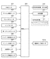
次に、自動変速機1の制御及びエンジンのアイドルストップ制御を行なう制御ユニット200について説明すると、図4に示すように、この制御ユニット200には、当該車両の速度を検出する車速センサ201からの信号と、アクセルペダルの踏み込み量を検出するアクセル開度センサ202からの信号と、ブレーキペダルの踏み込みを検出するブレーキスイッチ203からの信号と、ドライバによって選択されている自動変速機1のレンジを検出するレンジセンサ204からの信号と、第1クラッチ10に供給されている作動圧を検出する第1クラッチ圧センサ205からの信号と、当該車両に搭載されているバッテリの残容量を検出するバッテリ残容量センサ206からの信号と、エンジン水温を検出するエンジン水温センサ207からの信号と、当該車両の加速度及び減速度を検出する加速度センサ208からの信号と、エンジンの回転数を検出するエンジン回転数センサ209からの信号とが入力されるようになっている。
Next, the
そして、これらの信号に基づき、該制御ユニット200は、次のようにエンジンのアイドルストップ制御を行なう。
Based on these signals, the
即ち、所定のエンジンの自動停止条件が成立したとき、具体的には、バッテリの残容量が所定量以上であり、エンジン水温が所定温度以上の状態において、車速が所定車速以下であり、アクセル開度が所定開度以下であり、かつ、ブレーキペダルが踏み込まれたときに、エンジンの燃料供給装置や点火装置等のエンジンを作動させるための装置210にその作動を停止させるエンジン停止信号を出力してエンジンを自動停止させると共に、該エンジンの自動停止中にブレーキペダルの踏み込み解除などの自動再始動条件が成立したときに、前記装置210と始動装置211とにエンジン始動信号を出力してエンジンを自動再始動させる。
That is, when the predetermined engine automatic stop condition is satisfied, specifically, when the remaining battery capacity is equal to or higher than the predetermined amount, the engine water temperature is equal to or higher than the predetermined temperature, the vehicle speed is equal to or lower than the predetermined vehicle speed, and the accelerator is opened. When the degree is less than the predetermined opening and the brake pedal is depressed, an engine stop signal for stopping the operation is output to a
また、この制御ユニット200は、車速とアクセル開度とに基づき、選択されているレンジに応じた自動変速機1の変速制御を行なうと共に、アイドルストップ制御時に、第1油路103、104の油圧に応じて、自動変速機1の油圧制御回路100における電動ポンプ101を駆動するモータ101aに制御信号を出力することにより、アイドルストップ制御時における自動変速機1の摩擦要素の締結制御を行うようになっている。
In addition, the
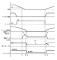
次に、図5に示すタイムチャートに従い、アイドルストップ制御時における自動変速機1の摩擦要素の締結の第1の制御について説明する。 Next, according to the time chart shown in FIG. 5, the first control for engaging the friction element of the automatic transmission 1 during the idle stop control will be described.
図5は、前進走行レンジとしてDレンジが選択されている状態で停車し、エンジンが自動停止した後、再始動する場合の制御を示すものであり、まず、エンジンの自動停止に先立ち、車速が所定車速V0(エンジン自動停止条件以上の車速)以下になった時点T1で電動ポンプ101を作動させ、その後、前述のエンジン自動停止条件が成立した時点T2でエンジンを自動停止させる。
FIG. 5 shows the control when the vehicle is stopped with the D range being selected as the forward travel range and the engine is automatically stopped and then restarted. First, prior to the automatic stop of the engine, the vehicle speed is The
このとき、エンジン駆動による機械ポンプ6が停止することにより、該機械ポンプ6から第1クラッチ10への作動圧の供給が停止されることになるが、図3の油圧制御回路100においては、機械ポンプ6の吐出圧が低下してライン103、104、108の圧力が所定圧未満になり、第1クラッチ圧が所定圧P10未満になる時点T3で、シフトバルブ106が第1状態から第2状態に切り換えられ、即ち該シフトバルブ106のスプール130が第1位置から第2位置に移動して、第1油路103、104が第3油路109に接続された状態から第2油路107が第3油路109に接続された状態に切り換えられる。
At this time, the supply of the operating pressure from the mechanical pump 6 to the first clutch 10 is stopped by stopping the mechanical pump 6 driven by the engine. However, in the
従って、エンジンの自動停止に先立つ時点T1で既に作動を開始している電動ポンプ101からの作動圧が機械ポンプ6からの作動圧に代わり、ライン109を介して第1クラッチ10に供給され、図5に符号アで示すように、第1クラッチ圧が供給されている状態、即ち第1クラッチ10が締結された状態が維持される。この電動ポンプ101で供給される第1クラッチ圧は、締結状態を維持するだけの比較的低い油圧に制御される。
Accordingly, the operating pressure from the
しかし、シフトバルブ106が第1状態から第2状態に切り換えられる際に第1クラッチ圧が一時的に低下することを抑制するために、電動ポンプ101は、符号イで示すように、締結状態を維持するだけの比較的低い油圧に第1クラッチ圧を制御するための吐出圧に比して、吐出圧が高くなるように制御される。
However, in order to prevent the first clutch pressure from temporarily lowering when the
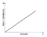
また、本実施形態では、制御ユニット200は、車速センサ201によって検出される車速と加速度センサ208によって検出される減速度からドライバによる減速要求を検出し、この減速要求に基づいて、電動ポンプ101の駆動を開始する所定車速V0を設定することができるようになっている。
In the present embodiment, the
図6は、要求減速度と電動ポンプ駆動開始車速との関係を示すグラフであり、この図6に示すように、制御ユニット200は、減速要求度が大きくなるにつれて、電動ポンプ101の駆動を開始する所定車速V0を高くするように設定する。即ち、制御ユニット200は、減速要求度が大きくなるにつれて、車速が高い車速で、電動ポンプ101の駆動を開始するように電動ポンプ101の駆動を制御する。これにより、第2油路107の油圧が高められる前に第1クラッチ10へのオイルの供給源が機械ポンプ6から電動ポンプ101に切り換えられることを抑制することができる。
FIG. 6 is a graph showing the relationship between the required deceleration and the electric pump drive start vehicle speed. As shown in FIG. 6, the
その後、時点T4で、エンジン再始動条件としてのブレーキペダルの踏み込みの解除が検出されると、エンジンが再始動されることになるが、自動変速機1は第1クラッチ10が締結された状態、即ち1速の状態が保持されているから、車両はアクセルペダルの踏み込みに応じて直ちに発進することになる。 Thereafter, when release of the depression of the brake pedal as the engine restart condition is detected at time T4, the engine is restarted, but the automatic transmission 1 is in a state where the first clutch 10 is engaged, That is, since the first speed state is maintained, the vehicle starts immediately in response to depression of the accelerator pedal.
そして、その後、エンジンの始動に伴う機械ポンプ6の作動開始により該機械ポンプ6の吐出圧が立ち上がり、シフトバルブ106が第2状態から第1状態へ切り換えられた時点T5で、該機械ポンプ6からの作動圧が第1クラッチ圧として第1クラッチ10に供給される。これにより、電動ポンプ101は役目を終了し、停止する。
After that, the discharge pressure of the mechanical pump 6 rises due to the start of the operation of the mechanical pump 6 accompanying the start of the engine, and at time T5 when the
その場合に、エンジン自動停止中、第1クラッチ圧は比較的低い油圧に制御されていたので、該第1クラッチ圧を車両の発進に必要な圧力まで速やかに上昇させるため、電動ポンプ101は、符合ウで示すように、停止する直前に吐出圧が一時的に高くなるように制御される。
In that case, since the first clutch pressure was controlled to a relatively low hydraulic pressure during the engine automatic stop, the
以上のようにして、第1クラッチ10は、エンジンの自動停止中も締結された状態が維持され、発進時に該第1クラッチ10を改めて締結することがないから、クラッチ締結時の応答遅れが防止されて良好な発進応答性が得られると共に、クラッチの締結によるショックの発生が抑制される。 As described above, the first clutch 10 is maintained in the engaged state even during the automatic stop of the engine, and the first clutch 10 is not re-engaged at the start, so that a response delay at the time of clutch engagement is prevented. Thus, a good start response can be obtained, and the occurrence of shock due to the engagement of the clutch is suppressed.
このように、本実施形態に係る自動変速機の制御装置は、摩擦要素10にオイルを供給するエンジン駆動の機械ポンプ6と、摩擦要素10にオイルを供給する電動ポンプ101と、該電動ポンプ101の駆動を制御するポンプ駆動制御手段200とを備えると共に、車両の停車時において所定のエンジン停止条件が成立したときにエンジンを自動停止すると共に、この自動停止状態で所定のエンジン再始動条件が成立したときに、エンジンを自動再始動させるアイドルストップ手段200を備えている。
As described above, the control device for the automatic transmission according to the present embodiment includes an engine-driven mechanical pump 6 that supplies oil to the
また、前記自動変速機の制御装置は、機械ポンプ6から導かれた第1油路103、104と、電動ポンプ101から導かれた第2油路107を前進発進段で締結される摩擦要素10に通じる第3油路109に選択的に接続し、アイドルストップ手段200によるエンジンの自動停止時に、第1油路104が第3油路109に接続された状態から第2油路107が第3油路109に接続された状態に切り換える油路切換手段106を備え、ポンプ駆動制御手段200は、油路切換手段106によって第1油路104から第2油路107に切り換えられる前に電動ポンプ101の駆動を開始するように電動ポンプ101の駆動を制御する。
In addition, the control device for the automatic transmission includes the
これにより、エンジンの自動停止時に、摩擦要素10へのオイルの供給源が機械ポンプ6から電動ポンプ101に切り換えられる前に電動ポンプ101の駆動を開始して第2油路107の油圧を予め高めておくことができるので、電動ポンプ101を絶えず駆動させている場合に比してエネルギー損失を少なくしつつ摩擦要素10へ供給される油圧が一時的に低下することを抑制することができる。従って、エンジン再始動時における摩擦要素10の締結の応答遅れによる発進性の悪化や、該摩擦要素10の締結時のショックの発生を抑制することができる。
Thus, when the engine is automatically stopped, before the oil supply source to the
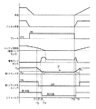
次に、図7に示すタイムチャートに従い、アイドルストップ制御時における自動変速機1の摩擦要素の締結の第2の制御について説明する。 Next, the second control of the engagement of the friction element of the automatic transmission 1 during the idle stop control will be described according to the time chart shown in FIG.
図7についても、前進走行レンジとしてDレンジが選択されている状態で停車し、エンジンが自動停止した後、再始動する場合の制御を示すものであるが、図7に示す制御では、車速が所定車速以下になった時点で電動ポンプ101を作動させるものではなく、エンジン自動停止条件が成立した時点で自動停止されるエンジンの回転数の低下に伴って機械ポンプ6の吐出圧が低下し、第1油路103、104の圧力が所定圧未満になりシフトバルブ106が第1状態から第2状態に切り換えられる切換タイミングを予測して、該切換タイミングから所定時間前の時点において電動ポンプ101を作動させるようにしたものである。
FIG. 7 also shows control in the case where the vehicle is stopped in a state where the D range is selected as the forward travel range and the engine is automatically stopped and then restarted. In the control shown in FIG. The
また、第2の制御では、第1クラッチ10に供給されている作動圧を検出する第1クラッチ圧センサ205は、第1油路103、104の油圧を検出する油圧検出手段として機能するようになっており、制御ユニット200にライン103、104の油圧が所定圧以上である場合にON信号を送り、ライン103、104の油圧が所定圧未満である場合にOFF信号を送る第1クラッチ圧スイッチとして機能している。
In the second control, the first
第2の制御ではまた、制御ユニット200は、第1クラッチ圧センサ205によって検出される第1油路103、104の油圧に基づいて、シフトバルブ106が第1状態から第2状態に切り換える切換タイミングを予測することができるようになっていると共に、予測される切換タイミングに基づいて、電動ポンプ101の駆動の開始を制御するようになっている。
In the second control, the
図7に示すように、まず、エンジンの自動停止条件が成立した時点T11で、エンジンを自動停止させる。エンジンを自動停止させる際には、エンジンの回転数が徐々に低くなり、これに伴って機械ポンプ6の吐出圧が低下し、第1油路103、104の油圧及び第1クラッチ圧が低下することとなる。
As shown in FIG. 7, first, the engine is automatically stopped at time T11 when the automatic engine stop condition is satisfied. When the engine is automatically stopped, the rotational speed of the engine gradually decreases, and accordingly, the discharge pressure of the mechanical pump 6 decreases, and the hydraulic pressures of the
本実施形態では、第1クラッチ圧センサ205によって検出される圧力が所定圧P20になり、第1クラッチ圧スイッチがOFFにされた時点T12で、制御ユニット200によって、シフトバルブ106が第1状態から第2状態に切り換えられる切換タイミングT14が予測される。このとき、制御ユニット200は、予測される切換タイミングT14から所定時間前の時点T13において電動ポンプ101の作動を開始させるように設定する。
In this embodiment, the pressure detected by the first
その後、エンジンの回転数がさらに低くなって、機械ポンプ6の吐出圧がさらに低下し、第1油路103、104の油圧及び第1クラッチ圧がさらに低下する時点T13において、電動ポンプ101を作動させる。そして、機械ポンプ6の吐出圧がさらに低下して第1油路103、104の油圧及びライン108の油圧が所定圧未満になり、第1クラッチ圧が所定圧P21未満になる時点T14で、シフトバルブ106が第1状態から第2状態に切り換えられ、電動ポンプ101からの作動圧が機械ポンプ6からの作動圧に代わり、ライン109を介して第1クラッチ10に供給され、図6に符号アで示すように、第1クラッチ圧が供給されている状態、即ち第1クラッチ10が締結された状態が維持される。
After that, the engine speed is further reduced, the discharge pressure of the mechanical pump 6 is further reduced, and the
その後、時点T15で、エンジン再始動条件としてのブレーキペダルの踏み込みの解除が検出されると、エンジンが再始動されることになるが、自動変速機1は第1クラッチ10が締結された状態、即ち1速の状態が保持されているから、車両はアクセルペダルの踏み込みに応じて直ちに発進することになる。 After that, when release of the depression of the brake pedal as the engine restart condition is detected at time T15, the engine is restarted, but the automatic transmission 1 is in a state where the first clutch 10 is engaged, That is, since the first speed state is maintained, the vehicle starts immediately in response to depression of the accelerator pedal.
そして、その後、エンジンの始動に伴う機械ポンプ6の作動開始により該機械ポンプ6の吐出圧が立ち上がり、シフトバルブ106が第2状態から第1状態へ切り換えられた時点T16で、該機械ポンプ6からの作動圧が第1クラッチ圧として第1クラッチ10に供給される。これにより、電動ポンプ101は役目を終了し、停止する。
Thereafter, the discharge pressure of the mechanical pump 6 rises due to the start of the operation of the mechanical pump 6 accompanying the start of the engine, and at time T16 when the
以上のようにして、第1クラッチ10は、エンジンの自動停止中も締結された状態が維持され、発進時に該第1クラッチ10を改めて締結することがないから、クラッチ締結時の応答遅れが防止されて良好な発進応答性が得られると共に、クラッチの締結によるショックの発生が抑制される。 As described above, the first clutch 10 is maintained in the engaged state even during the automatic stop of the engine, and the first clutch 10 is not re-engaged at the start, so that a response delay at the time of clutch engagement is prevented. Thus, a good start response can be obtained, and the occurrence of shock due to the engagement of the clutch is suppressed.
このように、第2の制御においても、本実施形態に係る自動変速機の制御装置は、機械ポンプ6から導かれた第1油路103、104と電動ポンプ101から導かれた第2油路107を前進発進段で締結される摩擦要素10に通じる第3油路109に選択的に接続し、アイドルストップ手段200によるエンジンの自動停止時に、第1油路103、104が第3油路109に接続された状態から第2油路107が第3油路109に接続された状態に切り換える油路切換手段106を備え、ポンプ駆動制御手段200は、油路切換手段106によって第1油路103、104から第2油路107に切り換えられる前に電動ポンプ101の駆動を開始するように電動ポンプ101の駆動を制御する。
As described above, also in the second control, the control device for the automatic transmission according to the present embodiment includes the
これにより、エンジンの自動停止時に、摩擦要素10へのオイルの供給源が機械ポンプ6から電動ポンプ101に切り換えられる前に電動ポンプ101の駆動を開始して第2油路107の油圧を予め高めておくことができるので、電動ポンプ101を絶えず駆動させている場合に比してエネルギー損失を少なくしつつ摩擦要素10へ供給される油圧が一時的に低下することを抑制することができる。
Thus, when the engine is automatically stopped, before the oil supply source to the
また、前記自動変速機の制御装置は、第1油路103、104の油圧を検出する油圧検出手段205と、該油圧検出手段205によって検出される第1油路103、104の油圧に基づいて、第1油路103、104が第3油路109に接続された状態から第2油路107が第3油路109に接続された状態に切り換えられる切換タイミングを予測する切換タイミング予測手段200とをさらに備え、ポンプ駆動制御手段200は、予測される切換タイミングに基づいて、電動ポンプ101の駆動を開始するように電動ポンプ101の駆動を制御することにより、電動ポンプ101の駆動開始を第1油路103、104が第3油路109に接続された状態から第2油路107が第3油路109に接続された状態に切り換えられる切換タイミングに基づいて好適に設定することができ、前記効果をより有効に奏することができる。
The control device for the automatic transmission is based on a hydraulic pressure detection means 205 that detects the hydraulic pressure of the
前述した第2の制御において、摩擦要素10に供給されるオイルの温度を検出する温度センサなどの温度検出手段を設け、制御ユニット200が、該温度検出手段によって検出されるオイルの温度が高い場合には該オイルの温度が低い場合に比して第1油路103、104から第2油路107への切換タイミングが早くなるように切換タイミングを予測するようにすることも可能である。
In the second control described above, when temperature detection means such as a temperature sensor for detecting the temperature of oil supplied to the
このように、摩擦要素10に供給されるオイルの温度を検出する油温検出手段をさらに備え、切換タイミング予測手段は、油温検出手段によって検出されるオイルの温度が高い場合には該オイルの温度が低い場合に比して切換タイミングが早くなるように切換タイミングを予測することにより、オイルの温度に基づいて変化するオイルの粘性を考慮することにより、切換タイミングの予測精度を向上させることができる。
As described above, the oil temperature detecting means for detecting the temperature of the oil supplied to the
なお、第2の制御では、第1クラッチ圧センサ205によってライン103、104の油圧を検出しているが、ライン103、104、108に該ライン103、104、108の油圧を検出する油圧センサなどの油圧検出手段を設け、かかる油圧検出手段によって検出される油圧に基づいて、シフトバルブ106の切換タイミングを予測し、予測される切換タイミングに基づいて電動ポンプ101の作動を開始するようにすることも可能である。
In the second control, the hydraulic pressure of the
以上のように、本発明は、例示された実施の形態に限定されるものではなく、本発明の要旨を逸脱しない範囲において、種々の改良及び設計上の変更が可能であることは言うまでもない。 As described above, the present invention is not limited to the illustrated embodiments, and it goes without saying that various improvements and design changes can be made without departing from the gist of the present invention.
以上のように、本発明によれば、アイドルストップ制御によるエンジン停止時に摩擦要素へのオイルの供給源をエンジン駆動による機械ポンプから電動ポンプに切り換える自動変速機が搭載された車両において、エネルギー損失を少なくしつつ摩擦要素へ供給される油圧が一時的に低下することを抑制することが可能となるから、この種の車両の製造産業分野において好適に利用される可能性がある。 As described above, according to the present invention, energy loss is reduced in a vehicle equipped with an automatic transmission that switches the oil supply source to the friction element from the mechanical pump driven by the engine to the electric pump when the engine is stopped by the idle stop control. Since it is possible to suppress the hydraulic pressure supplied to the friction element from being temporarily reduced while decreasing, there is a possibility that the hydraulic pressure supplied to the friction element is suitably used in the manufacturing industry of this type of vehicle.
1 自動変速機
6 機械ポンプ
10 第1クラッチ
101 電動ポンプ
103、104 第1油路
106 シフトバルブ
107 第2油路
109 第3油路
113 第4油路
114 オリフィス
200 制御ユニット
201 車速センサ
205 第1クラッチ圧センサ
208 加速度センサ
DESCRIPTION OF SYMBOLS 1 Automatic transmission 6 Mechanical pump 10
Claims (6)
前記機械式オイルポンプから導かれた第1油路と前記電動式オイルポンプから導かれた第2油路を前進発進段で締結される摩擦要素に通じる第3油路に選択的に接続し、前記アイドルストップ手段によるエンジンの自動停止時に、前記第1油路が第3油路に接続された状態から前記第2油路が第3油路に接続された状態に切り換える油路切換手段を備え、
前記ポンプ駆動制御手段は、前記油路切換手段によって前記第1油路が第3油路に接続された状態から前記第2油路が第3油路に接続された状態に切り換えられる前に前記電動式オイルポンプの駆動を開始するように前記電動式オイルポンプの駆動を制御する、
ことを特徴とする自動変速機の制御装置。 An engine-driven mechanical oil pump that supplies oil to the friction element, an electric oil pump that supplies oil to the friction element, and a pump drive control unit that controls driving of the electric oil pump, and a vehicle The engine is automatically stopped when a predetermined engine stop condition is satisfied when the vehicle stops, and an idle stop means is provided for automatically restarting the engine when the predetermined engine restart condition is satisfied in the automatic stop state. A control device for an automatic transmission,
Selectively connecting a first oil passage led from the mechanical oil pump and a second oil passage led from the electric oil pump to a third oil passage leading to a friction element fastened at a forward start stage; Oil path switching means for switching from a state in which the first oil path is connected to the third oil path to a state in which the second oil path is connected to the third oil path when the engine is automatically stopped by the idle stop means. ,
The pump drive control means is configured so that the oil passage switching means changes the state in which the first oil passage is connected to the third oil passage before the second oil passage is connected to the third oil passage. Controlling the driving of the electric oil pump so as to start the driving of the electric oil pump;
A control device for an automatic transmission.
前記第1油路の油圧を検出する油圧検出手段と、
該油圧検出手段によって検出される前記第1油路の油圧に基づいて、前記油路切換手段によって前記第1油路が第3油路に接続された状態から前記第2油路が第3油路に接続された状態に切り換えられる切換タイミングを予測する切換タイミング予測手段と、
をさらに備え、
前記ポンプ駆動制御手段は、前記切換タイミング予測手段によって予測される前記切換タイミングに基づいて、前記電動式オイルポンプの駆動を開始するように前記電動式オイルポンプの駆動を制御する、
ことを特徴とする請求項1に記載の自動変速機の制御装置。 The oil passage switching means connects the first oil passage to a third oil passage when the oil pressure of the first oil passage is equal to or higher than a predetermined pressure, and the oil pressure of the first oil passage is less than a predetermined pressure. And connecting the second oil passage to the third oil passage,
Oil pressure detecting means for detecting the oil pressure of the first oil passage;
Based on the oil pressure of the first oil passage detected by the oil pressure detecting means, the second oil passage is changed to the third oil from the state in which the first oil passage is connected to the third oil passage by the oil passage switching means. Switching timing prediction means for predicting switching timing to be switched to a state connected to the road;
Further comprising
The pump drive control means controls driving of the electric oil pump so as to start driving of the electric oil pump based on the switching timing predicted by the switching timing prediction means.
The control apparatus for an automatic transmission according to claim 1.
前記切換タイミング予測手段は、前記油温検出手段によって検出されるオイルの温度が高い場合には該オイルの温度が低い場合に比して前記切換タイミングが早くなるように前記切換タイミングを予測する、
ことを特徴とする請求項2に記載の自動変速機の制御装置。 Oil temperature detecting means for detecting the temperature of oil supplied to the friction element,
The switching timing prediction means predicts the switching timing so that the switching timing is earlier when the oil temperature detected by the oil temperature detection means is higher than when the oil temperature is low;
The control apparatus for an automatic transmission according to claim 2.
車両の車速を検出する車速検出手段と、
をさらに備え、
前記ポンプ駆動制御手段は、前記減速要求検出手段によって検出される前記減速要求が大きくなるにつれて、前記車速検出手段によって検出される車速が高い車速で、前記電動式オイルポンプの駆動を開始するように前記電動式オイルポンプの駆動を制御する、
ことを特徴とする請求項1に記載の自動変速機の制御装置。 Deceleration request detecting means for detecting a deceleration request by the driver;
Vehicle speed detecting means for detecting the vehicle speed of the vehicle;
Further comprising
The pump drive control means starts driving the electric oil pump at a higher vehicle speed detected by the vehicle speed detection means as the deceleration request detected by the deceleration request detection means becomes larger. Controlling the drive of the electric oil pump;
The control apparatus for an automatic transmission according to claim 1.
該第4油路にオリフィスが設けられている、
ことを特徴とする請求項1から請求項4の何れか1項に記載の自動変速機の制御装置。 A fourth oil passage connected to the second oil passage for lowering the hydraulic pressure of the second oil passage when driving of the electric oil pump is stopped;
An orifice is provided in the fourth oil passage;
The control device for an automatic transmission according to any one of claims 1 to 4, wherein the control device is an automatic transmission.
ことを特徴とする請求項1から請求項5の何れか1項に記載の自動変速機の制御装置。 The electric oil pump has a maximum capacity set smaller than that of the mechanical oil pump.
The control device for an automatic transmission according to any one of claims 1 to 5, wherein:
Priority Applications (1)
| Application Number | Priority Date | Filing Date | Title |
|---|---|---|---|
| JP2011013185A JP2012154392A (en) | 2011-01-25 | 2011-01-25 | Controller for automatic transmission |
Applications Claiming Priority (1)
| Application Number | Priority Date | Filing Date | Title |
|---|---|---|---|
| JP2011013185A JP2012154392A (en) | 2011-01-25 | 2011-01-25 | Controller for automatic transmission |
Publications (1)
| Publication Number | Publication Date |
|---|---|
| JP2012154392A true JP2012154392A (en) | 2012-08-16 |
Family
ID=46836327
Family Applications (1)
| Application Number | Title | Priority Date | Filing Date |
|---|---|---|---|
| JP2011013185A Pending JP2012154392A (en) | 2011-01-25 | 2011-01-25 | Controller for automatic transmission |
Country Status (1)
| Country | Link |
|---|---|
| JP (1) | JP2012154392A (en) |
Cited By (5)
| Publication number | Priority date | Publication date | Assignee | Title |
|---|---|---|---|---|
| JP2014105799A (en) * | 2012-11-28 | 2014-06-09 | Jatco Ltd | Control device and control method for electric oil pump |
| JP2014234855A (en) * | 2013-05-31 | 2014-12-15 | 富士重工業株式会社 | Vehicular control device |
| KR101640132B1 (en) * | 2015-10-30 | 2016-07-15 | 현대위아 주식회사 | 4WD motor pump control method for 4WD vehicle having ISG system |
| JP2017133543A (en) * | 2016-01-25 | 2017-08-03 | トヨタ自動車株式会社 | Vehicle electric pump control device |
| US12222032B2 (en) | 2021-07-02 | 2025-02-11 | Jatco Ltd | Control device for vehicle, control method for vehicle, and non-transitory computer-readable medium |
Citations (3)
| Publication number | Priority date | Publication date | Assignee | Title |
|---|---|---|---|---|
| JP2000046165A (en) * | 1998-07-30 | 2000-02-18 | Toyota Motor Corp | Control device for vehicle drive unit |
| JP2002371969A (en) * | 2001-06-14 | 2002-12-26 | Toyota Motor Corp | Automatic transmission oil pump controller |
| JP2010236693A (en) * | 2009-03-09 | 2010-10-21 | Toyota Motor Corp | Hydraulic control device for automatic transmission |
-
2011
- 2011-01-25 JP JP2011013185A patent/JP2012154392A/en active Pending
Patent Citations (3)
| Publication number | Priority date | Publication date | Assignee | Title |
|---|---|---|---|---|
| JP2000046165A (en) * | 1998-07-30 | 2000-02-18 | Toyota Motor Corp | Control device for vehicle drive unit |
| JP2002371969A (en) * | 2001-06-14 | 2002-12-26 | Toyota Motor Corp | Automatic transmission oil pump controller |
| JP2010236693A (en) * | 2009-03-09 | 2010-10-21 | Toyota Motor Corp | Hydraulic control device for automatic transmission |
Cited By (5)
| Publication number | Priority date | Publication date | Assignee | Title |
|---|---|---|---|---|
| JP2014105799A (en) * | 2012-11-28 | 2014-06-09 | Jatco Ltd | Control device and control method for electric oil pump |
| JP2014234855A (en) * | 2013-05-31 | 2014-12-15 | 富士重工業株式会社 | Vehicular control device |
| KR101640132B1 (en) * | 2015-10-30 | 2016-07-15 | 현대위아 주식회사 | 4WD motor pump control method for 4WD vehicle having ISG system |
| JP2017133543A (en) * | 2016-01-25 | 2017-08-03 | トヨタ自動車株式会社 | Vehicle electric pump control device |
| US12222032B2 (en) | 2021-07-02 | 2025-02-11 | Jatco Ltd | Control device for vehicle, control method for vehicle, and non-transitory computer-readable medium |
Similar Documents
| Publication | Publication Date | Title |
|---|---|---|
| US8758197B2 (en) | Idle stop control device for vehicle | |
| JP5323748B2 (en) | Hydraulic control device for automatic transmission | |
| US9267598B2 (en) | Automatic transmission control method, control device, and automatic transmission system | |
| JP5397332B2 (en) | Idle stop control device for vehicle | |
| JP6119690B2 (en) | Control device for automatic transmission | |
| JP2010281432A (en) | Hydraulic transmission device for automatic transmission | |
| JP2016017528A (en) | Automatic transmission control unit | |
| JP2012154392A (en) | Controller for automatic transmission | |
| JP2007176266A (en) | Shift control device for automatic transmission for vehicle | |
| JP6137141B2 (en) | Control device for vehicle with multi-stage automatic transmission | |
| JP5471898B2 (en) | Neutral control device for automatic transmission | |
| JP6115587B2 (en) | Control device for vehicle with multi-stage automatic transmission | |
| JP6191095B2 (en) | Transmission control device | |
| JP6007832B2 (en) | Automatic transmission and control device corresponding to open failure of hydraulic control valve in automatic transmission | |
| JP2012036842A (en) | Vehicular control system | |
| JP2009287681A (en) | Drive mechanism for power transmission device, and vehicle | |
| JP6119684B2 (en) | Control device for automatic transmission | |
| JP6137142B2 (en) | Control device for vehicle with multi-stage automatic transmission | |
| JP6222005B2 (en) | Powertrain control device | |
| JP5983034B2 (en) | Transmission control device | |
| CN104854378A (en) | Hydraulic control device | |
| JP2014202291A (en) | Vehicle with engine automatic stop function | |
| JP4734783B2 (en) | Vehicle power unit | |
| JP6206393B2 (en) | Hydraulic control device and hydraulic control method for automatic transmission | |
| JP6119694B2 (en) | Hydraulic control device for automatic transmission |
Legal Events
| Date | Code | Title | Description |
|---|---|---|---|
| A621 | Written request for application examination |
Free format text: JAPANESE INTERMEDIATE CODE: A621 Effective date: 20130313 |
|
| A131 | Notification of reasons for refusal |
Free format text: JAPANESE INTERMEDIATE CODE: A131 Effective date: 20131029 |
|
| A977 | Report on retrieval |
Free format text: JAPANESE INTERMEDIATE CODE: A971007 Effective date: 20131031 |
|
| A02 | Decision of refusal |
Free format text: JAPANESE INTERMEDIATE CODE: A02 Effective date: 20140311 |