JP2012154355A - Dust cover structure of hydraulic shock absorber - Google Patents
Dust cover structure of hydraulic shock absorber Download PDFInfo
- Publication number
- JP2012154355A JP2012154355A JP2011011252A JP2011011252A JP2012154355A JP 2012154355 A JP2012154355 A JP 2012154355A JP 2011011252 A JP2011011252 A JP 2011011252A JP 2011011252 A JP2011011252 A JP 2011011252A JP 2012154355 A JP2012154355 A JP 2012154355A
- Authority
- JP
- Japan
- Prior art keywords
- dust cover
- bellows
- shock absorber
- hydraulic shock
- region
- Prior art date
- Legal status (The legal status is an assumption and is not a legal conclusion. Google has not performed a legal analysis and makes no representation as to the accuracy of the status listed.)
- Pending
Links
Images

Classifications
-
- F—MECHANICAL ENGINEERING; LIGHTING; HEATING; WEAPONS; BLASTING
- F16—ENGINEERING ELEMENTS AND UNITS; GENERAL MEASURES FOR PRODUCING AND MAINTAINING EFFECTIVE FUNCTIONING OF MACHINES OR INSTALLATIONS; THERMAL INSULATION IN GENERAL
- F16F—SPRINGS; SHOCK-ABSORBERS; MEANS FOR DAMPING VIBRATION
- F16F9/00—Springs, vibration-dampers, shock-absorbers, or similarly-constructed movement-dampers using a fluid or the equivalent as damping medium
- F16F9/32—Details
- F16F9/38—Covers for protection or appearance
-
- F—MECHANICAL ENGINEERING; LIGHTING; HEATING; WEAPONS; BLASTING
- F16—ENGINEERING ELEMENTS AND UNITS; GENERAL MEASURES FOR PRODUCING AND MAINTAINING EFFECTIVE FUNCTIONING OF MACHINES OR INSTALLATIONS; THERMAL INSULATION IN GENERAL
- F16J—PISTONS; CYLINDERS; SEALINGS
- F16J3/00—Diaphragms; Bellows; Bellows pistons
- F16J3/04—Bellows
- F16J3/041—Non-metallic bellows
Abstract
Description
本発明は、油圧緩衝器のダストカバー構造に関する。 The present invention relates to a dust cover structure for a hydraulic shock absorber.
油圧緩衝器では、アウタチューブから突き出ているピストンロッドをダストカバーにより被覆し、ピストンロッドに泥が付着したり路面の石が当たるのを防いでいる。ダストカバーはゴム等を蛇腹状に成形したものであり、ピストンロッドの伸縮に伴なって伸縮する。 In the hydraulic shock absorber, the piston rod protruding from the outer tube is covered with a dust cover to prevent mud from adhering to the piston rod and hitting road stones. The dust cover is made of rubber or the like in a bellows shape and expands and contracts as the piston rod expands and contracts.
ダストカバーにあっては、圧縮途中で蛇腹部が径方向の一方側へ大きく撓み(以下、胴曲がりという)、周辺のコイルスプリング等に接触して破損するおそれがある。 In the dust cover, the bellows portion may be greatly bent toward one side in the radial direction during the compression (hereinafter referred to as a “body bend”), and may be damaged by contact with a surrounding coil spring or the like.
そこで、特許文献1に記載のダストカバーでは、長手方向に沿う上中下の各領域毎に、蛇腹部の山頂部の厚みを異なるようにし、胴曲がりを抑制できるとしている。 Therefore, in the dust cover described in Patent Document 1, the thickness of the peak portion of the bellows portion is made different for each of the upper, middle, and lower regions along the longitudinal direction, so that the bending of the body can be suppressed.
また、特許文献2に記載のダストカバーでは、長手方向に沿う端領域の蛇腹部の山の高さ(山頂部と谷底部の高さの差)を中間領域の蛇腹部の山の高さより高くすることにより、胴曲がりを抑制できるとしている。 Moreover, in the dust cover described in Patent Document 2, the height of the peak of the bellows portion in the end region along the longitudinal direction (the difference in height between the peak portion and the bottom of the valley) is higher than the height of the peak of the bellows portion in the intermediate region. By doing so, it is said that curling of the body can be suppressed.
特許文献1に記載のダストカバーは、長手方向に沿う各領域毎に蛇腹部の山頂部の厚みを異なるように成形するものであり、成形型や製造方法に高精度が必要とされ、製造困難である。 The dust cover described in Patent Document 1 is formed so that the thickness of the peak portion of the bellows portion is different for each region along the longitudinal direction, and high accuracy is required for the molding die and the manufacturing method, which makes it difficult to manufacture. It is.
特許文献2に記載のダストカバーは、長手方向に沿う各領域毎に蛇腹部の山の高さを異なるように成形するものであり、成形型や製造方法に高精度が必要とされ、製造困難である。 The dust cover described in Patent Document 2 is formed so that the height of the bellows portion is different for each region along the longitudinal direction, and high accuracy is required for the molding die and the manufacturing method, which makes it difficult to manufacture. It is.
本発明の課題は、油圧緩衝器のダストカバー構造において、胴曲がりを抑制できるダストカバーを簡易に製造できるようにすることにある。 An object of the present invention is to make it possible to easily manufacture a dust cover capable of suppressing body bending in a dust cover structure of a hydraulic shock absorber.
請求項1に係る発明は、油圧緩衝器のピストンロッドを蛇腹状ダストカバーにより被覆する油圧緩衝器のダストカバー構造において、ダストカバーを長手方向に沿う上中下の3領域に分け、上領域と下領域の蛇腹部の板厚を薄く、中間領域の蛇腹部の板厚を厚くしてなるようにしたものである。 The invention according to claim 1 is a dust cover structure for a hydraulic shock absorber in which a piston rod of a hydraulic shock absorber is covered with a bellows-shaped dust cover. The dust cover is divided into three regions, upper, middle, and lower, along the longitudinal direction. The plate thickness of the bellows portion in the lower region is made thin, and the plate thickness of the bellows portion in the middle region is made thick.
請求項2に係る発明は、請求項1に係る発明において更に、前記中間領域の蛇腹部の板厚を、上領域と下領域の蛇腹部の板厚より5〜15%厚くしてなるようにしたものである。 According to a second aspect of the present invention, in the first aspect of the invention, the plate thickness of the bellows portion of the intermediate region is 5 to 15% thicker than the plate thickness of the bellows portion of the upper region and the lower region. It is a thing.
請求項3に係る発明は、請求項1又は2に係る発明において更に、前記油圧緩衝器がストラット式であるようにしたものである。 The invention according to claim 3 is the invention according to claim 1 or 2, wherein the hydraulic shock absorber is a strut type.
(請求項1)
(a)上領域と下領域の蛇腹部の板厚を薄く(小剛性)、中間領域の蛇腹部の板厚を厚く(大剛性)した。これにより、小剛性で撓み易い上領域と下領域の蛇腹部を先に撓ませてダストカバーの全長を短くし、その後、大剛性で撓み難い中間領域の蛇腹部を撓ませる。
(Claim 1)
(a) The plate thickness of the bellows portion in the upper region and the lower region was thin (small rigidity), and the plate thickness of the bellows portion in the middle region was thick (large rigidity). Thereby, the bellows portions of the upper region and the lower region which are small and easy to bend are bent first to shorten the entire length of the dust cover, and thereafter the bellows portion of the middle region which is large and difficult to bend is bent.
上領域と下領域の蛇腹部は、剛性が小さい分だけ曲がり易いが、ダストカバーの全長に比して短尺とされている分だけ曲がり難く、かつ剛性が小さい分だけ直ちにたたまれ、胴曲がりを抑制される。 The upper and lower regions of the bellows are easy to bend due to their low rigidity, but they are difficult to bend as much as they are short compared to the total length of the dust cover, and they are folded immediately due to their low rigidity, and are bent Is suppressed.
中間領域の蛇腹部は、剛性が大きい分だけ胴曲がりし難い上に、ダストカバーの全長に比して短尺とされていて、更にダストカバーの全長が短くなってからたたまれ始めることから、中間領域の蛇腹部だけが仮に径方向の一方側へ撓んでもその径方向への張り出し量は大きくなく、胴曲がりを抑制できる。 The bellows part of the middle region is difficult to bend as much as the rigidity is high, and is shorter than the total length of the dust cover, and since it begins to fold after the total length of the dust cover becomes shorter, Even if only the bellows portion in the intermediate region is bent to one side in the radial direction, the amount of overhanging in the radial direction is not large, and the bending of the body can be suppressed.
即ち、一般的なダストカバーは長手方向の中間部で径方向への張り出し量が最大になって胴曲がりを生じ易く、上領域と下領域の蛇腹部から曲がり始め、中間領域の蛇腹部で大きく曲がって周辺のコイルスプリング等に干渉する。これに対し、本発明では、上領域と下領域の蛇腹部がたたまれる過程で多少曲がっても、大剛性の中間領域の蛇腹部は未だたたまれずに胴曲がりを発生しないし、上領域と下領域の蛇腹部がたたみ終われば、短く残る中間領域の蛇腹部が大剛性の故に曲がり難いし、短尺であって径方向への張り出し量も大きくなく、胴曲がりを生じない。これにより、ダストカバーの全体が胴曲がりを抑制されて伸縮できるものになる。 That is, a general dust cover has a maximum amount of protrusion in the radial direction at the middle portion in the longitudinal direction and is likely to bend, and starts to bend from the bellows portion in the upper region and the lower region, and becomes large at the bellows portion in the middle region. It bends and interferes with surrounding coil springs. On the other hand, in the present invention, even if the upper region and the lower region of the bellows portion are bent, the bellows portion of the high-rigidity intermediate region is not yet folded, and the upper region is not bent. When the bellows portion in the lower region is folded, the bellows portion in the intermediate region that remains short is difficult to bend because of its high rigidity, is short, does not have a large overhang in the radial direction, and does not bend. As a result, the entire dust cover can be expanded and contracted while curling the body.
(b)上領域と下領域の蛇腹部の板厚を全体的に薄く、中間領域の蛇腹部の板厚を全体的に厚く成形するだけで足り、成形型や製造方法に高精度が必要とされない。胴曲がりを抑制できるダストカバーを簡易に製造できる。 (b) It is only necessary to form the plate thickness of the bellows portion of the upper region and the lower region as a whole and the plate thickness of the bellows portion of the middle region as a whole, and high accuracy is required for the mold and the manufacturing method. Not. It is possible to easily manufacture a dust cover that can suppress body bending.
(請求項2)
(c)中間領域の蛇腹部の板厚を、上領域と下領域の蛇腹部の板厚より5〜15%厚くする。ダストカバーの胴曲がりを前述(a)によって確実に抑制できる。
(Claim 2)
(c) The plate thickness of the bellows portion in the middle region is made 5 to 15% thicker than the plate thickness of the bellows portion in the upper region and the lower region. The above-mentioned (a) can reliably suppress the bending of the dust cover.
(請求項3)
(d)油圧緩衝器がストラット式であるとき、車体側取付ブラケットに対し、ダンパチューブ及びピストンロッドが傾動し、結果としてダストカバーも傾動するものになる。このとき、ダストカバーは、車体側取付ブラケットに対して傾斜した状態で、ダンパチューブの伸縮により突き上げられるため、この突き上げにより胴曲がりし易く、ストラット式油圧緩衝器において前述(a)の胴曲がり抑制効果は大きい。
(Claim 3)
(d) When the hydraulic shock absorber is a strut type, the damper tube and the piston rod tilt with respect to the vehicle body side mounting bracket, and as a result, the dust cover also tilts. At this time, the dust cover is pushed up by the expansion and contraction of the damper tube in an inclined state with respect to the mounting bracket on the vehicle body side. The effect is great.
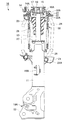
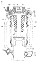
図1、図2に示す油圧緩衝器10は、ストラット式であり、ダンパチューブ11に内蔵してあるシリンダ(不図示)にピストンロッド12を挿入し、ダンパチューブ11に車輪側取付ブラケット13を備えて車輪に結合されるとともに、ダンパチューブ11から突き出るピストンロッド12に車体側取付ブラケット14を備えて車体に取付けられる。尚、車体側取付ブラケット14は、ステー15、上下のマウントベース16A、16B及びマウントラバー17からなるマウントラバー組立体14Aからなり、このマウントラバー組立体14Aのステー15をピストンロッド12の上端側小径部に挿入してナット18で締結することにて構成される。
A
油圧緩衝器10は、車輪側取付ブラケット13にロアアーム取付部19Aを備え、車体との間にロアアーム(不図示)を設け、ダンパチューブ11及びピストンロッド12を車体側取付ブラケット14に対し傾動可能にしている。尚、油圧緩衝器10は、ダンパチューブ11にスタビライザ取付部19Bを備え、スタビライザ(不図示)を取付け可能にしている。
The
油圧緩衝器10は、ダンパチューブ11とピストンロッド12を緩衝器本体とし、ダンパチューブ11の外周に固定した下スプリングシート21と、ピストンロッド12の周囲に設置されて車体側取付ブラケット14に軽圧入等で固定されて背面支持されたスラストベアリング23付きの上スプリングシート22との間に、コイルスプリング24を介装している。具体的には、コイルスプリング24は、下スプリングシート21にシートラバー21Aを介して支持されるとともに、上スプリングシート22にシートラバー22Aを介して支持される。
The
油圧緩衝器10は、車体側取付ブラケット14の下面に溶接してあるバンプラバー取付体25に、ピストンロッド12の車体側取付ブラケット14寄り下部に固く抱きつくように挿着したバンプラバー26を備える。油圧緩衝器10は、最圧縮時に、このバンプラバー26をダンパチューブ11の上端面のバンプストッパキャップ27に衝合して最圧縮ストロークを規制する。
The
油圧緩衝器10は、コイルスプリング24の内側、かつバンプラバー26の外側の環状スペースにダストカバー30を設けている。ダストカバー30は上スプリングシート22に設けられるシートラバー22Aの下端部に一体成形され、ダストカバー30の下端部をダンパチューブ11に設けたカバー受28に係止し、ダストカバー30によりダンパチューブ11及びピストンロッド12を被覆している。
The
即ち、油圧緩衝器10にあっては、車両が路面から受ける衝撃力をコイルスプリング24の弾発力により吸収するように伸縮する。そして、油圧緩衝器10は、その伸縮に伴うピストン(不図示)の上下動時に、ピストンに設けてあるピストンバルブ装置、シリンダに設けてあるベースバルブ装置等が発生する減衰力により、その伸縮振動を速やかに抑制するものである。
In other words, the hydraulic shock absorber 10 expands and contracts so that the impact force that the vehicle receives from the road surface is absorbed by the elastic force of the
しかるに、油圧緩衝器10にあっては、胴曲がりを抑制できるダストカバー30を簡易に製造できるようにするため、以下の構成を具備する。
However, the hydraulic shock absorber 10 has the following configuration in order to easily manufacture the
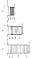
ダストカバー30は、図3に示す如く、シートラバー22Aの側を上端部31とし、カバー受28に係止される側を下端部32とし、上端部31と下端部32の間に蛇腹部33を備える。ダストカバー30は、多数の環状山頂部Mと環状谷底部Vを長手方向に交互に配置して蛇腹部33を形成してなる筒状成形体である。
As shown in FIG. 3, the
ダストカバー30は、蛇腹部33を長手方向に沿う上中下の3領域A〜Cに分け、上領域Aと下領域Cの蛇腹部33A、33Cの板厚Ta、Tcを薄く、中間領域Bの蛇腹部33Bの板厚Tbを厚くした。中間領域Bの蛇腹部33Bの板厚Tbを、上領域Aと下領域Cの蛇腹部33A、33Cの板厚Ta、Tcより5〜15%、より好適には10%厚くする。例えば、Ta、Tcを1mmとするとき、Tbを1.1mmとする。
The
本実施例において、蛇腹部33は全体形状をストレートな筒状とされ、各蛇腹部33A〜33Cの外径と内径を互いに概ね同一にする。また、蛇腹部33は、自由状態で、各蛇腹部33A〜33Cの山のピッチPを互いに同一にする。
In the present embodiment, the
ダストカバー30は、蛇腹部33の全長の上下1/4ずつを上領域Aと下領域Cの蛇腹部33A、33Cとし、残りの1/2を中間領域Bの蛇腹部33Bとする。又は、ダストカバー30は、蛇腹部33の全長の上下1/3ずつを上領域Aと下領域Cの蛇腹部33A、33Cとし、残りの1/3を中間領域Bの蛇腹部33Bとする。例えば、蛇腹部33の全体が20山からなるものであれば、上領域Aの6山分を蛇腹部33Aとし、下領域Cの7山分を蛇腹部33Cとし、中間領域Bの7山分を蛇腹部33Bとする。
In the
ダストカバー30は、NBR等のゴムを外型と内型の間で金型成形される。金型(外型と内型)は、中間領域Bの蛇腹部33B(板厚大)の成形部分の全体を、他の蛇腹部33A、33Cの成形部分よりも余分に切削するだけで製作でき、或いはポリオレフィン系熱可塑性エラストマー(TPO)、ポリエチレン、ポリエステルエラストマー等の合成樹脂をパリソンコントロールによって中間部を厚く成形すれば良く、高精度が必要とされない。金型における蛇腹部33Bの成形部分の山の角度、山の高さの精度も他の蛇腹部33A、33Cの成形部分と同じ一般公差内であれば良く、蛇腹部33Bの板厚を全体的に厚くし、大剛性とするものであれば良い。各蛇腹部33A〜33Cの外径や内径の寸法も互いに殆ど変化なく、一般公差内の範囲でも良い。
The
ダストカバー30の蛇腹部33が伸縮した状態を図4に示す。図4(A)は車両に取付ける前の伸切時の油圧緩衝器10に組込んだダストカバー30の小圧縮状態を示し、図4(B)は車両に取付けた空車状態の油圧緩衝器10内にあるダストカバー30の中間圧縮状態を示し、図4(C)は車両に取付けた最圧縮時の油圧緩衝器10内にあるダストカバー30の最圧縮状態を示す。尚、自由状態のダストカバー30は図示していないが、ダストカバー30の自由状態で各蛇腹部33A〜33Cの山のピッチPは前述の如く互いに同一である。
FIG. 4 shows a state where the
本実施例によれば、以下の作用効果を奏する。
(a)上領域Aと下領域Cの蛇腹部33A、33Cの板厚Ta、Tcを薄く(小剛性)、中間領域Bの蛇腹部33Bの板厚Tbを厚く(大剛性)した。これにより、小剛性で撓み易い上領域Aと下領域Cの蛇腹部33A、33Cを先に撓ませてダストカバー30の全長を短くし、その後、大剛性で撓み難い中間領域Bの蛇腹部33Bを撓ませる。
According to the present embodiment, the following operational effects can be obtained.
(a) The plate thicknesses Ta and Tc of the
上領域Aと下領域Cの蛇腹部33A、33Cは、剛性が小さい分だけ曲がり易いが、ダストカバー30の全長に比して短尺とされている分だけ曲がり難く、かつ剛性が小さい分だけ直ちにたたまれ、胴曲がりを抑制される。
The
中間領域Bの蛇腹部33Bは、剛性が大きい分だけ胴曲がりし難い上に、ダストカバー30の全長に比して短尺とされていて、更にダストカバー30の全長が短くなってからたたまれ始めることから、中間領域Bの蛇腹部33Bだけが仮に径方向の一方側へ撓んでもその径方向への張り出し量は大きくなく、胴曲がりを抑制できる。
The
即ち、一般的なダストカバー30は長手方向の中間部で径方向への張り出し量が最大になって胴曲がりを生じ易く、上領域Aと下領域Cの蛇腹部33A、33Cから曲がり始め、中間領域Bの蛇腹部33Bで大きく曲がって周辺のコイルスプリング24等に干渉する。これに対し、本発明では、上領域Aと下領域Cの蛇腹部33A、33Cがたたまれる過程で多少曲がっても、大剛性の中間領域Bの蛇腹部33Bは未だたたまれずに胴曲がりを発生しないし、上領域Aと下領域Cの蛇腹部33A、33Cがたたみ終われば、短く残る中間領域Bの蛇腹部33Bが大剛性の故に曲がり難いし、短尺であって径方向への張り出し量も大きくなく、胴曲がりを生じない。これにより、ダストカバー30の全体が胴曲がりを抑制されて伸縮できるものになる。
That is, the
(b)上領域Aと下領域Cの蛇腹部33A、33Cの板厚Ta、Tcを全体的に薄く、中間領域Bの蛇腹部33Bの板厚Tbを全体的に厚く成形するだけで足り、成形型や製造方法に高精度が必要とされない。胴曲がりを抑制できるダストカバー30を簡易に製造できる。
(b) It is only necessary to form the plate thicknesses Ta and Tc of the
(c)中間領域Bの蛇腹部33Bの板厚Tbを、上領域Aと下領域Cの蛇腹部33A、33Cの板厚Ta、Tcより5〜15%厚くする。ダストカバー30の胴曲がりを前述(a)によって確実に抑制できる。
(c) The plate thickness Tb of the
(d)油圧緩衝器10がストラット式であるとき、車体側取付ブラケット14に対し、ダンパチューブ11及びピストンロッド12が傾動し、結果としてダストカバー30も傾動するものになる。このとき、ダストカバー30は、車体側取付ブラケット14に対して傾斜した状態で、ダンパチューブ11の伸縮により突き上げられるため、この突き上げにより胴曲がりし易く、ストラット式油圧緩衝器において前述(a)の胴曲がり抑制効果は大きい。
(d) When the
以上、本発明の実施例を図面により詳述したが、本発明の具体的な構成はこの実施例に限られるものではなく、本発明の要旨を逸脱しない範囲の設計の変更等があっても本発明に含まれる。 The embodiment of the present invention has been described in detail with reference to the drawings. However, the specific configuration of the present invention is not limited to this embodiment, and even if there is a design change or the like without departing from the gist of the present invention. It is included in the present invention.
本発明は、油圧緩衝器のピストンロッドを蛇腹状ダストカバーにより被覆する油圧緩衝器のダストカバー構造において、ダストカバーを長手方向に沿う上中下の3領域に分け、上領域と下領域の蛇腹部の板厚を薄く、中間領域の蛇腹部の板厚を厚くした。これにより、油圧緩衝器のダストカバー構造において、胴曲がりを抑制できるダストカバーを簡易に製造できる。 The present invention relates to a dust cover structure of a hydraulic shock absorber in which a piston rod of a hydraulic shock absorber is covered with a bellows-like dust cover, and the dust cover is divided into three regions, upper, middle, and lower, along the longitudinal direction. The plate thickness of the part was made thin, and the plate thickness of the bellows part in the middle region was made thick. Thereby, in the dust cover structure of the hydraulic shock absorber, it is possible to easily manufacture a dust cover that can suppress body bending.
10 油圧緩衝器
12 ピストンロッド
30 ダストカバー
33 蛇腹部
33A 上領域の蛇腹部
33B 中間領域の蛇腹部
33C 下領域の蛇腹部
DESCRIPTION OF
Claims (3)
ダストカバーを長手方向に沿う上中下の3領域に分け、上領域と下領域の蛇腹部の板厚を薄く、中間領域の蛇腹部の板厚を厚くしてなることを特徴とする油圧緩衝器のダストカバー構造。 In the dust cover structure of the hydraulic shock absorber that covers the piston rod of the hydraulic shock absorber with the bellows-shaped dust cover,
The dust cover is divided into upper, middle, and lower three regions along the longitudinal direction, the upper and lower regions of the bellows are thinned, and the middle region is thickened. The dust cover structure of the vessel.
Priority Applications (3)
| Application Number | Priority Date | Filing Date | Title |
|---|---|---|---|
| JP2011011252A JP2012154355A (en) | 2011-01-21 | 2011-01-21 | Dust cover structure of hydraulic shock absorber |
| CA2752333A CA2752333A1 (en) | 2011-01-21 | 2011-09-14 | Dust cover structure of hydraulic shock absorber |
| US13/243,037 US20120241267A1 (en) | 2011-01-21 | 2011-09-23 | Dust cover structure of hydraulic shock absorber |
Applications Claiming Priority (1)
| Application Number | Priority Date | Filing Date | Title |
|---|---|---|---|
| JP2011011252A JP2012154355A (en) | 2011-01-21 | 2011-01-21 | Dust cover structure of hydraulic shock absorber |
Publications (1)
| Publication Number | Publication Date |
|---|---|
| JP2012154355A true JP2012154355A (en) | 2012-08-16 |
Family
ID=46514937
Family Applications (1)
| Application Number | Title | Priority Date | Filing Date |
|---|---|---|---|
| JP2011011252A Pending JP2012154355A (en) | 2011-01-21 | 2011-01-21 | Dust cover structure of hydraulic shock absorber |
Country Status (3)
| Country | Link |
|---|---|
| US (1) | US20120241267A1 (en) |
| JP (1) | JP2012154355A (en) |
| CA (1) | CA2752333A1 (en) |
Cited By (1)
| Publication number | Priority date | Publication date | Assignee | Title |
|---|---|---|---|---|
| JP2016048081A (en) * | 2014-08-27 | 2016-04-07 | 株式会社ショーワ | Suspension device and cover member |
Families Citing this family (6)
| Publication number | Priority date | Publication date | Assignee | Title |
|---|---|---|---|---|
| CN104870855B (en) * | 2012-12-26 | 2017-04-26 | 丰田自动车株式会社 | Suspension device for vehicle and method for assembling suspension device for vehicle |
| JP5613280B2 (en) * | 2013-03-22 | 2014-10-22 | 東海ゴム工業株式会社 | Dust cover |
| JP5998162B2 (en) * | 2014-02-06 | 2016-09-28 | Kyb株式会社 | shock absorber |
| CN104373499A (en) * | 2014-11-12 | 2015-02-25 | 四川宁江山川机械有限责任公司 | Novel comprehensive dust cover of shock absorber |
| US10618366B2 (en) * | 2016-07-08 | 2020-04-14 | Continental Automotive Systems, Inc. | Vehicle air strut with twist lock closure cover |
| CN107642551A (en) * | 2017-10-26 | 2018-01-30 | 南京溧水丽华弹簧厂 | A kind of spring dust cover |
Citations (11)
| Publication number | Priority date | Publication date | Assignee | Title |
|---|---|---|---|---|
| JPS6092689U (en) * | 1983-11-30 | 1985-06-25 | カヤバ工業株式会社 | front fork boots |
| JPH0449396Y2 (en) * | 1988-05-18 | 1992-11-20 | ||
| JPH10159975A (en) * | 1996-11-22 | 1998-06-16 | Inoac Corp | Bellows type cylinder |
| JPH10213223A (en) * | 1997-01-30 | 1998-08-11 | Showa:Kk | Dust boot and manufacture thereof |
| JPH10267124A (en) * | 1997-03-24 | 1998-10-09 | Fukoku Bussan Kk | Bellows body |
| JPH10331897A (en) * | 1997-05-28 | 1998-12-15 | American Showa Inc | Dust cover for shock absorber and its manufacture |
| JPH1126443A (en) * | 1997-07-08 | 1999-01-29 | Dainippon Screen Mfg Co Ltd | Substrate-processing apparatus |
| JP2005009528A (en) * | 2003-06-17 | 2005-01-13 | Tokai Rubber Ind Ltd | Method of manufacturing dust cover |
| WO2007049429A1 (en) * | 2005-10-25 | 2007-05-03 | Nok Corporation | Boot for universal joint |
| JP2009068527A (en) * | 2007-09-10 | 2009-04-02 | Toyo Tire & Rubber Co Ltd | Dust cover and method of manufacturing dust cover |
| JP2009236195A (en) * | 2008-03-26 | 2009-10-15 | Toyota Motor Corp | Dust cover |
Family Cites Families (2)
| Publication number | Priority date | Publication date | Assignee | Title |
|---|---|---|---|---|
| US5192057A (en) * | 1991-08-12 | 1993-03-09 | Miner Enterprises, Inc. | Elastomer rebound, jounce and related compression springs |
| JP2006308002A (en) * | 2005-04-28 | 2006-11-09 | Kaneka Corp | Resin boot |
-
2011
- 2011-01-21 JP JP2011011252A patent/JP2012154355A/en active Pending
- 2011-09-14 CA CA2752333A patent/CA2752333A1/en not_active Abandoned
- 2011-09-23 US US13/243,037 patent/US20120241267A1/en not_active Abandoned
Patent Citations (12)
| Publication number | Priority date | Publication date | Assignee | Title |
|---|---|---|---|---|
| JPS6092689U (en) * | 1983-11-30 | 1985-06-25 | カヤバ工業株式会社 | front fork boots |
| JPH0449396Y2 (en) * | 1988-05-18 | 1992-11-20 | ||
| JPH10159975A (en) * | 1996-11-22 | 1998-06-16 | Inoac Corp | Bellows type cylinder |
| JPH10213223A (en) * | 1997-01-30 | 1998-08-11 | Showa:Kk | Dust boot and manufacture thereof |
| JPH10267124A (en) * | 1997-03-24 | 1998-10-09 | Fukoku Bussan Kk | Bellows body |
| JPH10331897A (en) * | 1997-05-28 | 1998-12-15 | American Showa Inc | Dust cover for shock absorber and its manufacture |
| JPH1126443A (en) * | 1997-07-08 | 1999-01-29 | Dainippon Screen Mfg Co Ltd | Substrate-processing apparatus |
| JP2005009528A (en) * | 2003-06-17 | 2005-01-13 | Tokai Rubber Ind Ltd | Method of manufacturing dust cover |
| WO2007049429A1 (en) * | 2005-10-25 | 2007-05-03 | Nok Corporation | Boot for universal joint |
| US20090131180A1 (en) * | 2005-10-25 | 2009-05-21 | Ntn Corporation | Boot for Universal Joint |
| JP2009068527A (en) * | 2007-09-10 | 2009-04-02 | Toyo Tire & Rubber Co Ltd | Dust cover and method of manufacturing dust cover |
| JP2009236195A (en) * | 2008-03-26 | 2009-10-15 | Toyota Motor Corp | Dust cover |
Cited By (1)
| Publication number | Priority date | Publication date | Assignee | Title |
|---|---|---|---|---|
| JP2016048081A (en) * | 2014-08-27 | 2016-04-07 | 株式会社ショーワ | Suspension device and cover member |
Also Published As
| Publication number | Publication date |
|---|---|
| CA2752333A1 (en) | 2012-07-21 |
| US20120241267A1 (en) | 2012-09-27 |
Similar Documents
| Publication | Publication Date | Title |
|---|---|---|
| JP2012154355A (en) | Dust cover structure of hydraulic shock absorber | |
| JP6435741B2 (en) | Bump stopper cap | |
| US7090058B2 (en) | Dust cover receiving structure of shock absorber | |
| US8191692B2 (en) | Cylinder apparatus | |
| US20160107496A1 (en) | Air spring | |
| JP5700896B1 (en) | Cover member and shock absorber | |
| JP5661593B2 (en) | Vehicle suspension system | |
| EP3124823A1 (en) | Shock absorber | |
| JP2013155841A (en) | Suspension device and cover member | |
| JP2010223316A (en) | Mounting member of shock absorber | |
| JP6078449B2 (en) | Cover member | |
| WO2016072426A1 (en) | Cylinder device and cover member | |
| WO2015141047A1 (en) | Cover member and shock-absorbing device | |
| JP2016089935A (en) | Cylinder device and cover member | |
| JP2015017628A (en) | Damper | |
| WO2014188889A1 (en) | Bump stop | |
| JP2014105775A (en) | Bump stopper | |
| JP7394721B2 (en) | stopper | |
| JP2010276137A (en) | Strut mount | |
| JP7191863B2 (en) | vibration absorber | |
| WO2020158462A1 (en) | Vehicular suspension device, and suspension device spring | |
| JP7394720B2 (en) | stopper | |
| JP2013177935A (en) | Suspension device and cover member | |
| JP5657464B2 (en) | Air spring | |
| JP5937491B2 (en) | Shock absorber |
Legal Events
| Date | Code | Title | Description |
|---|---|---|---|
| A621 | Written request for application examination |
Free format text: JAPANESE INTERMEDIATE CODE: A621 Effective date: 20131028 |
|
| A977 | Report on retrieval |
Free format text: JAPANESE INTERMEDIATE CODE: A971007 Effective date: 20140523 |
|
| A131 | Notification of reasons for refusal |
Free format text: JAPANESE INTERMEDIATE CODE: A131 Effective date: 20140527 |
|
| A521 | Written amendment |
Free format text: JAPANESE INTERMEDIATE CODE: A523 Effective date: 20140617 |
|
| A02 | Decision of refusal |
Free format text: JAPANESE INTERMEDIATE CODE: A02 Effective date: 20140708 |