JP2012151236A - Liquid processing apparatus and liquid processing method - Google Patents

Liquid processing apparatus and liquid processing method Download PDF

Info

Publication number
JP2012151236A
JP2012151236A JP2011008047A JP2011008047A JP2012151236A JP 2012151236 A JP2012151236 A JP 2012151236A JP 2011008047 A JP2011008047 A JP 2011008047A JP 2011008047 A JP2011008047 A JP 2011008047A JP 2012151236 A JP2012151236 A JP 2012151236A
Authority
JP
Japan
Prior art keywords
fluid
nozzle
arm
processing chamber
nozzle support
Prior art date
Legal status (The legal status is an assumption and is not a legal conclusion. Google has not performed a legal analysis and makes no representation as to the accuracy of the status listed.)
Granted
Application number
JP2011008047A
Other languages
Japanese (ja)
Other versions
JP5248633B2 (en
Inventor
Jiro Tojima
島 治 郎 東
Current Assignee (The listed assignees may be inaccurate. Google has not performed a legal analysis and makes no representation or warranty as to the accuracy of the list.)
Tokyo Electron Ltd
Original Assignee
Tokyo Electron Ltd
Priority date (The priority date is an assumption and is not a legal conclusion. Google has not performed a legal analysis and makes no representation as to the accuracy of the date listed.)
Filing date
Publication date
Application filed by Tokyo Electron Ltd filed Critical Tokyo Electron Ltd
Priority to JP2011008047A priority Critical patent/JP5248633B2/en
Priority to KR1020110126664A priority patent/KR101699984B1/en
Priority to TW101101756A priority patent/TWI544558B/en
Priority to US13/351,773 priority patent/US9159594B2/en
Publication of JP2012151236A publication Critical patent/JP2012151236A/en
Application granted granted Critical
Publication of JP5248633B2 publication Critical patent/JP5248633B2/en
Active legal-status Critical Current
Anticipated expiration legal-status Critical

Links

Images

Classifications

    • HELECTRICITY
    • H01ELECTRIC ELEMENTS
    • H01LSEMICONDUCTOR DEVICES NOT COVERED BY CLASS H10
    • H01L21/00Processes or apparatus adapted for the manufacture or treatment of semiconductor or solid state devices or of parts thereof
    • H01L21/67Apparatus specially adapted for handling semiconductor or electric solid state devices during manufacture or treatment thereof; Apparatus specially adapted for handling wafers during manufacture or treatment of semiconductor or electric solid state devices or components ; Apparatus not specifically provided for elsewhere
    • H01L21/67005Apparatus not specifically provided for elsewhere
    • H01L21/67011Apparatus for manufacture or treatment
    • H01L21/67017Apparatus for fluid treatment
    • H01L21/67028Apparatus for fluid treatment for cleaning followed by drying, rinsing, stripping, blasting or the like
    • H01L21/6704Apparatus for fluid treatment for cleaning followed by drying, rinsing, stripping, blasting or the like for wet cleaning or washing
    • H01L21/67051Apparatus for fluid treatment for cleaning followed by drying, rinsing, stripping, blasting or the like for wet cleaning or washing using mainly spraying means, e.g. nozzles
    • HELECTRICITY
    • H01ELECTRIC ELEMENTS
    • H01LSEMICONDUCTOR DEVICES NOT COVERED BY CLASS H10
    • H01L21/00Processes or apparatus adapted for the manufacture or treatment of semiconductor or solid state devices or of parts thereof
    • H01L21/67Apparatus specially adapted for handling semiconductor or electric solid state devices during manufacture or treatment thereof; Apparatus specially adapted for handling wafers during manufacture or treatment of semiconductor or electric solid state devices or components ; Apparatus not specifically provided for elsewhere
    • H01L21/67005Apparatus not specifically provided for elsewhere
    • H01L21/67011Apparatus for manufacture or treatment
    • H01L21/67017Apparatus for fluid treatment
    • H01L21/67063Apparatus for fluid treatment for etching
    • H01L21/67075Apparatus for fluid treatment for etching for wet etching
    • H01L21/6708Apparatus for fluid treatment for etching for wet etching using mainly spraying means, e.g. nozzles

Abstract

PROBLEM TO BE SOLVED: To provide a liquid processing apparatus and a liquid processing method which allow multiple nozzle support arms to move into a processing chamber.SOLUTION: A liquid processing apparatus 10 includes: a processing chamber 20; nozzles 82a for supplying a fluid to a substrate W held by a substrate holding part 21; nozzle support arms 82 supporting the nozzles 82a; and an arm standby part 80 provided adjacent to the processing chamber 20 and used as a place in which the nozzle support arms 82 withdrawn from the processing chamber 20 stand by. In the liquid processing apparatus 10, the multiple nozzle support arms 82p to 82u are provided, and the nozzle support arms 82p, 82r, 82t are positioned at a height different from the nozzle support arms 82q, 82s, 82u.

Description

本発明は、基板を水平状態に保持した状態で回転させながら当該基板に処理液を供給することにより基板の洗浄処理やエッチング処理、メッキ処理、現像処理等の液処理を行う液処理装置および液処理方法に関する。   The present invention relates to a liquid processing apparatus and a liquid processing apparatus for performing liquid processing such as cleaning processing, etching processing, plating processing, and development processing of a substrate by supplying a processing liquid to the substrate while rotating the substrate while being held in a horizontal state. It relates to the processing method.

従来から、半導体ウエハ等の基板(以下、ウエハともいう)を水平状態に保持した状態で回転させながら当該基板の表面や裏面に処理液を供給することにより基板の洗浄処理やエッチング処理、メッキ処理、現像処理等の液処理を行う液処理装置として、様々な種類のものが知られている(例えば、特許文献1等参照)。特許文献1には、基板をスピンチャックにより水平に保持して回転させ、スピンチャックにより保持されて回転する基板の表面に処理液を供給するような、基板を1枚ずつ処理する枚葉式の液処理装置が開示されている。また、このような枚葉式の液処理装置において、処理室の上方にFFU(ファンフィルタユニット)を設け、このFFUからN2ガス(窒素ガス)やクリーンエア等のガスをダウンフローで処理室内に送るような技術が知られている。   Conventionally, a substrate cleaning process, an etching process, or a plating process is performed by supplying a processing liquid to the front and back surfaces of the substrate while rotating the substrate such as a semiconductor wafer (hereinafter also referred to as a wafer) in a horizontal state while rotating the substrate. Various types of liquid processing apparatuses that perform liquid processing such as development processing are known (see, for example, Patent Document 1). Patent Document 1 discloses a single-wafer type that processes substrates one by one such that a substrate is horizontally held by a spin chuck and rotated, and a processing liquid is supplied to the surface of the substrate held and rotated by the spin chuck. A liquid processing apparatus is disclosed. Further, in such a single wafer type liquid processing apparatus, an FFU (fan filter unit) is provided above the processing chamber, and a gas such as N2 gas (nitrogen gas) or clean air is flowed down from the FFU into the processing chamber. Sending technology is known.

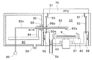
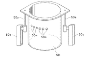
処理室の上方にFFUが設けられた液処理装置の構成について図11および図12を用いて説明する。図11は、従来の液処理装置の概略的な構成を示す側面図であり、図12は、図11に示す従来の液処理装置の上面図である。図11および図12に示すように、従来の液処理装置200は、ウエハWが収容され、この収容されたウエハWの液処理が行われる処理室(チャンバー)210を備えている。図11および図12に示すように、処理室210内には、ウエハWを保持して回転させるための保持部220が設けられており、この保持部220の周囲にはカップ230が配設されている。また、従来の液処理装置200では、保持部220に保持されたウエハWに対してカップ230の上方から処理液を供給するためのノズル240およびこのノズル240を支持するアーム241が処理室210内に設けられている。また、アーム241には略鉛直方向に延びるアーム支持部242が設けられており、このアーム支持部242によりアーム241が支持されている。そして、アーム支持部242は図示しない駆動機構により正逆両方向に回転駆動させられるようになっている。このことにより、アーム241はアーム支持部242を中心として正逆両方向に回転可能となり、このアーム241は、保持部220により保持されたウエハWに処理液を供給する進出位置(図12の実線参照)とカップ230から退避した退避位置(図12の二点鎖線参照)との間でアーム支持部242を中心として回転移動を行うようになる(図12の矢印参照)。   A configuration of a liquid processing apparatus in which an FFU is provided above the processing chamber will be described with reference to FIGS. 11 and 12. FIG. 11 is a side view showing a schematic configuration of a conventional liquid processing apparatus, and FIG. 12 is a top view of the conventional liquid processing apparatus shown in FIG. As shown in FIGS. 11 and 12, a conventional liquid processing apparatus 200 includes a processing chamber (chamber) 210 in which a wafer W is accommodated and liquid processing of the accommodated wafer W is performed. As shown in FIGS. 11 and 12, a holding unit 220 for holding and rotating the wafer W is provided in the processing chamber 210, and a cup 230 is disposed around the holding unit 220. ing. Further, in the conventional liquid processing apparatus 200, the nozzle 240 for supplying the processing liquid to the wafer W held by the holding unit 220 from above the cup 230 and the arm 241 that supports the nozzle 240 are provided in the processing chamber 210. Is provided. Further, the arm 241 is provided with an arm support portion 242 extending in a substantially vertical direction, and the arm 241 is supported by the arm support portion 242. The arm support portion 242 can be driven to rotate in both forward and reverse directions by a drive mechanism (not shown). As a result, the arm 241 can rotate in both forward and reverse directions around the arm support portion 242, and the arm 241 is an advanced position for supplying the processing liquid to the wafer W held by the holding portion 220 (see the solid line in FIG. 12). ) And the retracted position retracted from the cup 230 (see the two-dot chain line in FIG. 12), the arm support portion 242 is rotated (see the arrow in FIG. 12).

また、図11に示すように、処理室210の上方にはFFU(ファンフィルタユニット)250が設けられており、このFFU250からN2ガス(窒素ガス)やクリーンエア等のガスが常にダウンフローで処理室210内に送られるようになっている。また、処理室210の底部には排気部260が設けられており、この排気部260により処理室210内の雰囲気の排気が行われるようになっている。このように、FFU250から処理室210内にクリーンエア等のガスがダウンフローで送られ、このガスが排気部260により排気されることにより、処理室210内の雰囲気の置換が行われるようになっている。   As shown in FIG. 11, an FFU (fan filter unit) 250 is provided above the processing chamber 210, and a gas such as N 2 gas (nitrogen gas) or clean air is always processed from the FFU 250 in a down flow. It is sent into the chamber 210. An exhaust unit 260 is provided at the bottom of the processing chamber 210, and the exhaust of the atmosphere in the processing chamber 210 is performed by the exhaust unit 260. As described above, a gas such as clean air is sent from the FFU 250 into the processing chamber 210 in a down flow, and the gas in the processing chamber 210 is replaced by exhausting the gas by the exhaust unit 260. ing.

特開2009−94525号公報JP 2009-94525 A

図11および図12に示すような従来の液処理装置200では、ノズル240を支持するアーム241やこのアーム241を支持するアーム支持部242が処理室210内に設けられている。このため、図11および図12に示すような従来の液処理装置200では、アーム241に付着した汚れが処理室210内のウエハWに落下して付着してしまうおそれがある。また、処理室210内でウエハWの液処理を行う際に薬液等が飛散してアーム241に付着すると、この薬液がアーム241に残存してしまい、その後のウエハWの処理においてこの残存した薬液の雰囲気によりウエハWが汚れてしまう等の悪影響を与えてしまうおそれがある。   In the conventional liquid processing apparatus 200 as shown in FIGS. 11 and 12, an arm 241 that supports the nozzle 240 and an arm support portion 242 that supports the arm 241 are provided in the processing chamber 210. For this reason, in the conventional liquid processing apparatus 200 as shown in FIGS. 11 and 12, dirt attached to the arm 241 may fall and adhere to the wafer W in the processing chamber 210. Further, when the chemical solution or the like is scattered and adheres to the arm 241 when the wafer W is processed in the processing chamber 210, the chemical solution remains in the arm 241, and the remaining chemical solution is processed in the subsequent processing of the wafer W. There is a risk of adverse effects such as contamination of the wafer W by the atmosphere.

本発明は、このような点を考慮してなされたものであり、ノズルを支持するノズル支持アームを処理室から退避させてアーム待機部で待機させることにより、基板の液処理を行う際に飛散した薬液がノズル支持アームに付着しないようにすることができ、また、処理室内に複数のノズル支持アームが進出可能な液処理装置および液処理方法を提供することを目的とする。   The present invention has been made in consideration of such points, and the nozzle support arm that supports the nozzles is retracted from the processing chamber and waited in the arm standby unit, so that it is scattered when performing substrate liquid processing. It is an object of the present invention to provide a liquid processing apparatus and a liquid processing method that can prevent the chemical liquid from adhering to the nozzle support arm and that allow a plurality of nozzle support arms to advance into the processing chamber.

本発明の液処理装置は、基板を保持する基板保持部および当該基板保持部の周囲に配設されるカップが内部に設けられた処理室と、前記基板保持部に保持された基板に対して流体を供給するためのノズルと、前記ノズルを支持し、前記処理室内に進出した進出位置と前記処理室から退避した退避位置との間で水平方向に移動自在となっているノズル支持アームと、前記処理室に隣接して設けられ、当該処理室から退避した前記ノズル支持アームが待機するためのアーム待機部と、前記処理室と前記アーム待機部との間に設けられた鉛直方向に延びる壁と、を備え、前記ノズル支持アームは複数設けられており、少なくとも一つのノズル支持アームは他のノズル支持アームと高さレベルが異なるようになっていることを特徴とする。   The liquid processing apparatus of the present invention includes a substrate holding unit for holding a substrate, a processing chamber in which a cup disposed around the substrate holding unit is provided, and a substrate held by the substrate holding unit. A nozzle for supplying fluid; a nozzle support arm that supports the nozzle and is movable in a horizontal direction between an advanced position that has advanced into the processing chamber and a retracted position that has retracted from the processing chamber; An arm standby portion provided adjacent to the processing chamber for the nozzle support arm retracted from the processing chamber to stand by, and a wall extending in the vertical direction provided between the processing chamber and the arm standby portion And a plurality of the nozzle support arms are provided, and at least one nozzle support arm has a height level different from that of the other nozzle support arms.

このような液処理装置によれば、ノズル支持アームは複数設けられており、少なくとも一つのノズル支持アームは他のノズル支持アームと高さレベルが異なるようになっているので、高さレベルの異なる2以上のノズル支持アームが処理室内に進出しても、処理室内に進出した2以上のノズル支持アーム同士が互いに衝突してしまうことを防止することができる。   According to such a liquid processing apparatus, a plurality of nozzle support arms are provided, and at least one nozzle support arm has a different height level from the other nozzle support arms. Even if two or more nozzle support arms advance into the processing chamber, it is possible to prevent two or more nozzle support arms that have advanced into the processing chamber from colliding with each other.

本発明の液処理装置においては、高さレベルが互いに異なる複数の前記ノズル支持アームが同時に前記処理室内に進出することができるようになっていてもよい。   In the liquid processing apparatus of the present invention, a plurality of the nozzle support arms having different height levels may be able to advance into the processing chamber at the same time.

具体的には、第1の流体を供給するためのノズルを支持する前記ノズル支持アームが、前記第1の流体とは種類が異なる第2の流体を供給するためのノズルを支持する前記ノズル支持アームと高さレベルが異なるようになっており、前記基板保持部に保持された基板に対して前記第1の流体を供給した後に当該基板における前記第1の流体が供給された箇所に前記第2の流体を供給する際に、前記第1の流体を供給するためのノズルを支持する前記ノズル支持アームおよび前記第2の流体を供給するためのノズルを支持する前記ノズル支持アームが同時に前記処理室内に進出するようになっていてもよい。   Specifically, the nozzle support arm that supports the nozzle for supplying the first fluid supports the nozzle for supplying the second fluid that is different from the first fluid. The height level is different from that of the arm, and after the first fluid is supplied to the substrate held by the substrate holding part, the first fluid is supplied to the portion of the substrate where the first fluid is supplied. When the second fluid is supplied, the nozzle support arm that supports the nozzle for supplying the first fluid and the nozzle support arm that supports the nozzle for supplying the second fluid are simultaneously subjected to the processing. You may come to advance indoors.

この際に、前記第1の流体はIPAであり、前記第2の流体はガスであり、前記基板保持部に保持された基板に対して前記第1の流体であるIPAを供給した後に当該基板におけるIPAが供給された箇所に前記第2の流体であるガスを供給することにより基板の乾燥処理が行われるようになっていてもよい。   At this time, the first fluid is IPA, the second fluid is gas, and the substrate after the IPA as the first fluid is supplied to the substrate held by the substrate holding unit. The substrate may be dried by supplying the gas that is the second fluid to the location where the IPA is supplied.

また、第1の流体を供給するためのノズルを支持する前記ノズル支持アームが、前記第1の流体とは種類が異なる第2の流体を供給するためのノズルを支持する前記ノズル支持アームと高さレベルが異なるようになっており、前記基板保持部に保持された基板に対して前記第1の流体を供給した後に引き続き当該基板に前記第2の流体を供給する際に、前記第1の流体を供給するためのノズルを支持する前記ノズル支持アームおよび前記第2の流体を供給するためのノズルを支持する前記ノズル支持アームが同時に前記処理室内に進出するようになっていてもよい。   The nozzle support arm that supports the nozzle for supplying the first fluid has a height higher than the nozzle support arm that supports the nozzle for supplying the second fluid that is different from the first fluid. When the second fluid is continuously supplied to the substrate after the first fluid is supplied to the substrate held by the substrate holder, the first fluid level is different. The nozzle support arm that supports the nozzle for supplying the fluid and the nozzle support arm that supports the nozzle for supplying the second fluid may advance into the processing chamber at the same time.

この際に、前記第1の流体は薬液であり、前記第2の流体は水であり、前記基板保持部に保持された基板に対して前記第1の流体である薬液を供給した後に引き続き当該基板に前記第2の流体である水を供給することにより基板の薬液処理およびリンス処理が連続して行われるようになっていてもよい。   At this time, the first fluid is a chemical solution, the second fluid is water, and the chemical solution that is the first fluid is continuously supplied to the substrate held by the substrate holding unit. By supplying water as the second fluid to the substrate, the chemical treatment and rinsing treatment of the substrate may be performed continuously.

本発明の液処理装置においては、前記各ノズル支持アームは、前記処理室内と前記アーム待機部との間で直進運動を行うようになっていてもよい。   In the liquid processing apparatus of the present invention, each of the nozzle support arms may be configured to perform a straight movement between the processing chamber and the arm standby unit.

本発明の液処理方法は、処理室の内部に設けられた基板保持部により基板を保持させる工程と、ノズルを支持するノズル支持アームを前記処理室内に進出させる工程と、前記処理室内に進出したノズル支持アームのノズルにより、前記基板保持部により保持された基板に流体を供給する工程と、を備え、前記ノズル支持アームは複数設けられており、第1の流体を供給するためのノズルを支持する前記ノズル支持アームが、前記第1の流体とは種類が異なる第2の流体を供給するためのノズルを支持する前記ノズル支持アームと高さレベルが異なるようになっており、前記基板保持部に保持された基板に対して前記第1の流体を供給する際に、前記第1の流体を供給するためのノズルによる流体の吐出位置の近傍に前記第2の流体を供給するためのノズルが位置するよう、前記第1の流体を供給するためのノズルを支持する前記ノズル支持アームおよび前記第2の流体を供給するためのノズルを支持する前記ノズル支持アームが同時に前記処理室内に進出することを特徴とする。   The liquid processing method of the present invention includes a step of holding a substrate by a substrate holding portion provided inside the processing chamber, a step of moving a nozzle support arm that supports a nozzle into the processing chamber, and a step into the processing chamber. And a step of supplying a fluid to the substrate held by the substrate holding portion by a nozzle of the nozzle support arm, and a plurality of the nozzle support arms are provided to support the nozzle for supplying the first fluid. The nozzle support arm has a height level different from that of the nozzle support arm for supporting a nozzle for supplying a second fluid of a type different from the first fluid, and the substrate holding portion When supplying the first fluid to the substrate held on the substrate, the second fluid is supplied in the vicinity of a fluid discharge position by a nozzle for supplying the first fluid. The nozzle support arm for supporting the nozzle for supplying the first fluid and the nozzle support arm for supporting the nozzle for supplying the second fluid are simultaneously disposed in the processing chamber so that the nozzle for supplying the first fluid is positioned. It is characterized by advancing to.

本発明の液処理装置および液処理方法によれば、処理室内に複数のノズル支持アームを進出させることができる。   According to the liquid processing apparatus and the liquid processing method of the present invention, a plurality of nozzle support arms can be advanced into the processing chamber.

本発明の実施の形態による液処理装置を含む液処理システムを上方から見た上面図である。It is the top view which looked at the liquid processing system containing the liquid processing apparatus by embodiment of this invention from upper direction. 本発明の実施の形態による液処理装置の概略的な構成を示す上面図である。It is a top view which shows schematic structure of the liquid processing apparatus by embodiment of this invention. 図2に示す液処理装置の側面図である。It is a side view of the liquid processing apparatus shown in FIG. 図2に示す液処理装置の構成の詳細を示す縦断面図であって、カップ外周筒が下方位置にあるときの状態を示す図である。It is a longitudinal cross-sectional view which shows the detail of a structure of the liquid processing apparatus shown in FIG. 2, Comprising: It is a figure which shows a state when a cup outer periphery cylinder exists in a downward position. 図2に示す液処理装置の構成の詳細を示す縦断面図であって、カップ外周筒が上方位置にあるときの状態を示す図である。It is a longitudinal cross-sectional view which shows the detail of a structure of the liquid processing apparatus shown in FIG. 2, Comprising: It is a figure which shows a state when a cup outer periphery cylinder exists in an upper position. (a)は、図4等に示す液処理装置における保持プレートに設けられた保持部材の構成を示す拡大縦断面図であり、(b)は、(a)に示す状態からリフトピンプレートが下方に移動したときの状態を示す拡大縦断面図であり、(c)は、(b)に示す状態からリフトピンプレートが更に下方に移動したときの状態を示す拡大縦断面図である。(A) is an expanded longitudinal cross-sectional view which shows the structure of the holding member provided in the holding plate in the liquid processing apparatus shown in FIG. 4 etc., (b) is a lift pin plate below from the state shown in (a). It is an expanded longitudinal cross-sectional view which shows the state when it moves, (c) is an enlarged longitudinal cross-sectional view which shows a state when a lift pin plate moves further below from the state shown in (b). 図4等に示す液処理装置におけるカップ外周筒の構成を示す斜視図である。It is a perspective view which shows the structure of the cup outer periphery cylinder in the liquid processing apparatus shown in FIG. 図2等に示す液処理装置における処理室および6つのノズル支持アームを示す斜視図である。It is a perspective view which shows the process chamber and six nozzle support arms in the liquid processing apparatus shown in FIG. 図7に示すノズル支持アームの拡大斜視図である。FIG. 8 is an enlarged perspective view of the nozzle support arm shown in FIG. 7. 図7等に示す各ノズル支持アームを、これらのノズル支持アームの後方から処理室に向かって見たときの構成を示す図である。It is a figure which shows a structure when each nozzle support arm shown in FIG. 7 etc. is seen toward the process chamber from the back of these nozzle support arms. 図7等に示すノズル支持アームの構成の詳細を示す側断面図である。It is a sectional side view which shows the detail of a structure of the nozzle support arm shown in FIG. 従来の液処理装置の概略的な構成を示す側面図である。It is a side view which shows the schematic structure of the conventional liquid processing apparatus. 図11に示す従来の液処理装置の上面図である。It is a top view of the conventional liquid processing apparatus shown in FIG.

以下、図面を参照して本発明の実施の形態について説明する。図1乃至図10は、本実施の形態による液処理装置を示す図である。より詳細には、図1は、本発明の実施の形態による液処理装置を含む液処理システムを上方から見た上面図である。また、図2は、本発明の実施の形態による液処理装置の概略的な構成を示す上面図であり、図3は、図2に示す液処理装置の概略的な構成を示す側面図である。また、図4および図5は、図2に示す液処理装置の構成の詳細を示す縦断面図である。また、図6Aは、図4等に示す液処理装置における保持プレートに設けられた保持部材の構成を示す拡大縦断面図であり、図6Bは、図4等に示す液処理装置におけるカップ外周筒の構成を示す斜視図である。また、図7乃至図10は、図2等に示す液処理装置に設けられたノズル支持アームの構成を示す図である。   Embodiments of the present invention will be described below with reference to the drawings. 1 to 10 are diagrams showing a liquid processing apparatus according to the present embodiment. More specifically, FIG. 1 is a top view of a liquid processing system including a liquid processing apparatus according to an embodiment of the present invention as viewed from above. FIG. 2 is a top view showing a schematic configuration of the liquid processing apparatus according to the embodiment of the present invention, and FIG. 3 is a side view showing the schematic configuration of the liquid processing apparatus shown in FIG. . 4 and 5 are longitudinal sectional views showing details of the configuration of the liquid processing apparatus shown in FIG. 6A is an enlarged longitudinal sectional view showing a configuration of a holding member provided on a holding plate in the liquid processing apparatus shown in FIG. 4 and the like, and FIG. 6B is a cup outer peripheral cylinder in the liquid processing apparatus shown in FIG. 4 and the like. It is a perspective view which shows the structure. 7 to 10 are diagrams showing the configuration of the nozzle support arm provided in the liquid processing apparatus shown in FIG.

まず、図1を用いて、本実施の形態による液処理装置を含む液処理システムについて説明する。図1に示すように、液処理システムは、外部から被処理基板としての半導体ウエハ等の基板W(以下、ウエハWともいう)を収容したキャリアを載置するための載置台101と、キャリアに収容されたウエハWを取り出すための搬送アーム102と、搬送アーム102によって取り出されたウエハWを載置するための棚ユニット103と、棚ユニット103に載置されたウエハWを受け取り、当該ウエハWを液処理装置10内に搬送する搬送アーム104と、を備えている。図1に示すように、液処理システムには、複数(図1に示す態様では4個)の液処理装置10が設けられている。   First, a liquid processing system including a liquid processing apparatus according to the present embodiment will be described with reference to FIG. As shown in FIG. 1, a liquid processing system includes a mounting table 101 for mounting a carrier containing a substrate W (hereinafter also referred to as a wafer W) such as a semiconductor wafer as a substrate to be processed, and a carrier. A transfer arm 102 for taking out the accommodated wafer W, a shelf unit 103 for placing the wafer W taken out by the transfer arm 102, a wafer W placed on the shelf unit 103 are received, and the wafer W And a transport arm 104 for transporting the liquid into the liquid processing apparatus 10. As shown in FIG. 1, the liquid processing system is provided with a plurality (four in the embodiment shown in FIG. 1) of liquid processing apparatuses 10.

次に、本実施の形態による液処理装置10の概略的な構成について図2および図3を用いて説明する。   Next, a schematic configuration of the liquid processing apparatus 10 according to the present embodiment will be described with reference to FIGS. 2 and 3.

図2および図3に示すように、本実施の形態による液処理装置10は、ウエハWが収容され、この収容されたウエハWの液処理が行われる処理室(チャンバー)20を備えている。図3に示すように、処理室20内には、ウエハWを水平状態で保持して回転させるための保持部21が設けられており、この保持部21の周囲にはリング状の回転カップ40が配設されている。また、図2および図3に示すように、処理室20内において回転カップ40の周囲には円筒状のカップ外周筒50が配設されている。後述するように、このカップ外周筒50はウエハWの処理状況に応じて昇降可能となっている。これらの保持部21、回転カップ40およびカップ外周筒50の構成の詳細については後述する。   As shown in FIGS. 2 and 3, the liquid processing apparatus 10 according to the present embodiment includes a processing chamber (chamber) 20 in which a wafer W is accommodated and liquid processing of the accommodated wafer W is performed. As shown in FIG. 3, a holding unit 21 for holding and rotating the wafer W in a horizontal state is provided in the processing chamber 20, and a ring-shaped rotary cup 40 is provided around the holding unit 21. Is arranged. As shown in FIGS. 2 and 3, a cylindrical cup outer cylinder 50 is disposed around the rotary cup 40 in the processing chamber 20. As will be described later, the cup outer peripheral cylinder 50 can be raised and lowered according to the processing state of the wafer W. Details of the configurations of the holding portion 21, the rotating cup 40, and the cup outer peripheral cylinder 50 will be described later.

また、液処理装置10には、保持部21に保持されたウエハWに対してウエハWの上方から処理液やN2ガス等の流体を供給するためのノズル82aおよびこのノズル82aを支持するノズル支持アーム82が設けられている。図2に示すように、1つの液処理装置10には複数(具体的には例えば6つ)のノズル支持アーム82が設けられており、各ノズル支持アーム82の先端にノズル82aが設けられている。また、図3に示すように、各ノズル支持アーム82にはアーム支持部84が設けられており、各アーム支持部84は後述するアーム駆動機構85によって図3における左右方向に駆動されるようになっている。このことにより、各ノズル支持アーム82は、ノズル82aが処理室20内に進出した進出位置と、ノズル82aが処理室20から退避した退避位置との間で水平方向に直線運動を行うようになっている(図2および図3における各ノズル支持アーム82に設けられた矢印参照)。また、図3に示すように、各ノズル支持アーム82には表面処理液供給管82mが設けられており、各表面処理液供給管82mは表面処理液供給部89に接続されている。そして、表面処理液供給部89から各表面処理液供給管82mを介して各ノズル支持アーム82のノズル82aに処理液やN2ガス等の流体が供給されるようになっている。   Further, the liquid processing apparatus 10 includes a nozzle 82a for supplying a processing liquid and a fluid such as N 2 gas from above the wafer W to the wafer W held by the holding unit 21, and a nozzle support for supporting the nozzle 82a. An arm 82 is provided. As shown in FIG. 2, a plurality of (specifically, for example, six) nozzle support arms 82 are provided in one liquid processing apparatus 10, and a nozzle 82 a is provided at the tip of each nozzle support arm 82. Yes. Further, as shown in FIG. 3, each nozzle support arm 82 is provided with an arm support portion 84, and each arm support portion 84 is driven in the left-right direction in FIG. 3 by an arm drive mechanism 85 described later. It has become. As a result, each nozzle support arm 82 linearly moves in a horizontal direction between the advanced position where the nozzle 82a has advanced into the processing chamber 20 and the retracted position where the nozzle 82a has retracted from the processing chamber 20. (See the arrows provided on each nozzle support arm 82 in FIGS. 2 and 3). As shown in FIG. 3, each nozzle support arm 82 is provided with a surface treatment liquid supply pipe 82 m, and each surface treatment liquid supply pipe 82 m is connected to a surface treatment liquid supply part 89. A fluid such as a treatment liquid or N 2 gas is supplied from the surface treatment liquid supply unit 89 to the nozzles 82a of the nozzle support arms 82 via the respective surface treatment liquid supply pipes 82m.

図2および図3に示すように、液処理装置10において、アーム待機部80が処理室20に隣接して設けられている。このアーム待機部80において、処理室20から退避したノズル支持アーム82が待機するようになっている。また、アーム待機部80と処理室20との間には鉛直方向に延びる壁90が設けられている。この壁90は、各ノズル支持アーム82が通過可能な開口88pが設けられたアーム洗浄部88を有している。このアーム洗浄部88により各ノズル支持アーム82の洗浄が行われるようになっている。アーム洗浄部88の構成の詳細については後述する。   As shown in FIGS. 2 and 3, in the liquid processing apparatus 10, an arm standby unit 80 is provided adjacent to the processing chamber 20. In this arm standby section 80, the nozzle support arm 82 retracted from the processing chamber 20 is on standby. A wall 90 extending in the vertical direction is provided between the arm standby unit 80 and the processing chamber 20. The wall 90 has an arm cleaning portion 88 provided with an opening 88p through which each nozzle support arm 82 can pass. The nozzle cleaning arm 82 is cleaned by the arm cleaning unit 88. Details of the configuration of the arm cleaning unit 88 will be described later.

また、図3に示すように、処理室20の上方にはFFU(ファンフィルタユニット)70が設けられており、このFFU70からN2ガス(窒素ガス)やクリーンエア等のガスがダウンフローで処理室20内に送られるようになっている。また、図2および図3に示すように、処理室20の底部におけるカップ外周筒50の内側には排気部54が設けられており、この排気部54により処理室20内の雰囲気の排気が行われるようになっている。このように、FFU70から処理室20内にクリーンエア等のガスがダウンフローで送られ、このガスが排気部54により排気されることにより、処理室20内の雰囲気の置換が行われるようになっている。   Further, as shown in FIG. 3, an FFU (fan filter unit) 70 is provided above the processing chamber 20, and a gas such as N 2 gas (nitrogen gas) or clean air is flowed down from the FFU 70 in the processing chamber. 20 to be sent. As shown in FIGS. 2 and 3, an exhaust portion 54 is provided inside the cup outer peripheral cylinder 50 at the bottom of the processing chamber 20, and the exhaust portion 54 exhausts the atmosphere in the processing chamber 20. It has come to be. As described above, a gas such as clean air is sent from the FFU 70 into the processing chamber 20 in a down flow, and the gas in the processing chamber 20 is replaced by exhausting the gas by the exhaust unit 54. ing.

また、図2および図3に示すように、処理室20の底部におけるカップ外周筒50の外側には排気部56が設けられており、この排気部56により処理室20内の雰囲気の排気が行われるようになっている。この排気部56により、処理室20内におけるカップ外周筒50の外側の雰囲気の排気を行うことができるようになっている。具体的には、排気部56により、アーム待機部80内の雰囲気がカップ外周筒50内に入り込むことが抑止される。また、この排気部56により、カップ外周筒50内の雰囲気がアーム待機部80に出てしまうことが抑止される。   As shown in FIGS. 2 and 3, an exhaust portion 56 is provided outside the cup outer peripheral cylinder 50 at the bottom of the processing chamber 20, and the exhaust portion 56 exhausts the atmosphere in the processing chamber 20. It has come to be. The exhaust part 56 can exhaust the atmosphere outside the cup outer peripheral cylinder 50 in the processing chamber 20. Specifically, the exhaust unit 56 prevents the atmosphere in the arm standby unit 80 from entering the cup outer peripheral cylinder 50. Further, the exhaust part 56 prevents the atmosphere in the cup outer cylinder 50 from coming out to the arm standby part 80.

また、図2および図3に示すように、アーム待機部80の底部には排気部58が設けられており、この排気部58によりアーム待機部80内の雰囲気の排気が行われるようになっている。具体的には、各ノズル支持アーム82を駆動するためのアーム駆動機構85(後述)から発生するパーティクルを排気部58により引くことができるようになっている。   As shown in FIGS. 2 and 3, an exhaust unit 58 is provided at the bottom of the arm standby unit 80, and the atmosphere in the arm standby unit 80 is exhausted by the exhaust unit 58. Yes. Specifically, particles generated from an arm drive mechanism 85 (described later) for driving each nozzle support arm 82 can be drawn by the exhaust unit 58.

また、図2に示すように、液処理装置10の処理室20およびアーム待機部80の出入口にはそれぞれメンテナンス用のシャッター60、62が設けられている。処理室20およびアーム待機部80にそれぞれメンテナンス用のシャッター60、62が設けられていることにより、これらの処理室20内やアーム待機部80内の機器を個別にメンテナンスすることができる。また、処理室20内でウエハWを処理している最中でも、シャッター62を開くことによりアーム待機部80内の機器をメンテナンスすることができるようになる。   As shown in FIG. 2, shutters 60 and 62 for maintenance are provided at the processing chamber 20 of the liquid processing apparatus 10 and the entrance / exit of the arm standby unit 80, respectively. Since the processing chamber 20 and the arm standby unit 80 are provided with maintenance shutters 60 and 62, respectively, the devices in the process chamber 20 and the arm standby unit 80 can be individually maintained. In addition, while the wafer W is being processed in the processing chamber 20, it is possible to maintain the equipment in the arm standby unit 80 by opening the shutter 62.

また、図2に示すように、液処理装置10の側壁には、搬送アーム104により処理室20内へウエハWを搬入したり処理室20からウエハWを搬出したりするための開口94aが設けられており、この開口94aには、当該開口94aを開閉するためのシャッター94が設けられている。   In addition, as shown in FIG. 2, an opening 94 a is provided on the side wall of the liquid processing apparatus 10 for carrying the wafer W into the processing chamber 20 by the transfer arm 104 and carrying the wafer W out of the processing chamber 20. The opening 94a is provided with a shutter 94 for opening and closing the opening 94a.

なお、図2に示す液処理装置10において、処理室20内におけるカップ外周筒50の内部の領域はクリーンルームに対して微陽圧となっており、一方、処理室20内におけるカップ外周筒50の外側の領域はクリーンルームに対して微陰圧となっている。このため、処理室20内において、カップ外周筒50の内部の領域の気圧はカップ外周筒50の外側の領域の気圧よりも大きくなっている。   In the liquid processing apparatus 10 shown in FIG. 2, the region inside the cup outer cylinder 50 in the processing chamber 20 is slightly positive with respect to the clean room, while the cup outer cylinder 50 in the processing chamber 20 is The outer area has a slight negative pressure against the clean room. For this reason, in the processing chamber 20, the air pressure in the region inside the cup outer peripheral tube 50 is larger than the air pressure in the region outside the cup outer peripheral tube 50.

次に、図2および図3に示すような液処理装置10の構成の詳細について図4および図5を用いて説明する。   Next, details of the configuration of the liquid processing apparatus 10 as shown in FIGS. 2 and 3 will be described with reference to FIGS. 4 and 5.

図4および図5に示すように、保持部21は、ウエハWを保持するための円板形状の保持プレート26と、保持プレート26の上方に設けられた円板形状のリフトピンプレート22とを備えている。リフトピンプレート22の上面には、ウエハWを下方から支持するためのリフトピン23が周方向に等間隔で3つ設けられている。なお、図4および図5では2つのリフトピン23のみを表示している。また、リフトピンプレート22にはピストン機構24が設けられており、このピストン機構24によりリフトピンプレート22が昇降するようになっている。より具体的には、搬送アーム104(図1参照)によりウエハWをリフトピン23上に載置したりリフトピン23上からウエハWを取り出したりするときには、ピストン機構24によりリフトピンプレート22が図4等に示すような位置から上方に移動させられ、このリフトピンプレート22は回転カップ40よりも上方に位置するようになる。一方、処理室20内でウエハWの液処理を行う際には、ピストン機構24によりリフトピンプレート22が図4等に示すような下方位置に移動させられ、ウエハWの周囲に回転カップ40が位置するようになる。   As shown in FIGS. 4 and 5, the holding unit 21 includes a disk-shaped holding plate 26 for holding the wafer W, and a disk-shaped lift pin plate 22 provided above the holding plate 26. ing. Three lift pins 23 for supporting the wafer W from below are provided on the upper surface of the lift pin plate 22 at equal intervals in the circumferential direction. In FIGS. 4 and 5, only two lift pins 23 are shown. The lift pin plate 22 is provided with a piston mechanism 24, and the lift pin plate 22 is moved up and down by the piston mechanism 24. More specifically, when the wafer W is placed on the lift pins 23 or taken out from the lift pins 23 by the transfer arm 104 (see FIG. 1), the lift pin plate 22 is moved to the position shown in FIG. The lift pin plate 22 is moved upward from a position as shown, and the lift pin plate 22 is positioned above the rotary cup 40. On the other hand, when liquid processing of the wafer W is performed in the processing chamber 20, the lift pin plate 22 is moved to a lower position as shown in FIG. 4 etc. by the piston mechanism 24, and the rotary cup 40 is positioned around the wafer W. Will come to do.

保持プレート26には、ウエハWを側方から支持するための保持部材25が周方向に等間隔で3つ設けられている。なお、図4および図5では2つの保持部材25のみを表示している。各保持部材25は、リフトピンプレート22が上方位置から図4および図5に示すような下方位置に移動したときにこのリフトピン23上のウエハWを支持し、このウエハWをリフトピン23からわずかに離間させるようになっている。   The holding plate 26 is provided with three holding members 25 for supporting the wafer W from the side at equal intervals in the circumferential direction. In FIGS. 4 and 5, only two holding members 25 are shown. Each holding member 25 supports the wafer W on the lift pins 23 when the lift pin plate 22 is moved from the upper position to the lower position as shown in FIGS. 4 and 5, and the wafer W is slightly separated from the lift pins 23. It is supposed to let you.

リフトピンプレート22および保持プレート26の構成について、図6Aを用いてより詳細に説明する。図6Aにおいて、(a)は、リフトピンプレート22が上方位置から図4等に示すような下方位置に移動する途中での状態を示す図であり、(b)は、(a)に示す状態からリフトピンプレート22が下方に移動したときの状態を示す図であり、(c)は、(b)に示す状態からリフトピンプレート22が更に下方に移動し、リフトピンプレート22が図4等に示すような下方位置に到達したときの状態を示す図である。   The configuration of the lift pin plate 22 and the holding plate 26 will be described in more detail with reference to FIG. 6A. In FIG. 6A, (a) is a figure which shows the state in the middle of the lift pin plate 22 moving to the downward position as shown in FIG. 4 etc. from an upper position, (b) is from the state shown to (a). It is a figure which shows a state when the lift pin plate 22 moves below, (c) is a state where the lift pin plate 22 moves further downward from the state shown in (b), and the lift pin plate 22 is as shown in FIG. It is a figure which shows a state when reaching a downward position.

図6Aに示すように、保持部材25は軸25aを介して保持プレート26に軸支されている。より詳細には、図6Aに示すように、保持プレート26には軸受け部26aが取り付けられており、この軸受け部26aに設けられた軸受け孔26bに軸25aが受け入れられる。軸受け孔26bは水平方向に延びるような細長い孔からなり、保持部材25の軸25aはこの軸受け孔26bに沿って水平方向に移動することができる。このようにして、保持部材25は、軸受け部26aの軸受け孔26bに受け入れられた軸25aを中心として揺動することができる。   As shown in FIG. 6A, the holding member 25 is pivotally supported by the holding plate 26 via a shaft 25a. More specifically, as shown in FIG. 6A, a bearing portion 26a is attached to the holding plate 26, and the shaft 25a is received in a bearing hole 26b provided in the bearing portion 26a. The bearing hole 26b is an elongated hole extending in the horizontal direction, and the shaft 25a of the holding member 25 can move in the horizontal direction along the bearing hole 26b. In this way, the holding member 25 can swing around the shaft 25a received in the bearing hole 26b of the bearing portion 26a.

保持部材25の軸25aには、ねじりバネ等のバネ部材25dが巻き掛けられている。このバネ部材25dは、軸25aを中心として保持部材25を図6Aにおける時計回りの方向に回転させるような力を保持部材25に付勢するようになっている。これにより、保持部材25に何ら力が加えられていない場合には、保持部材25が保持プレート26に対して傾斜した状態となり、保持部材25におけるウエハWを側方から支持するための支持部分25b(後述)は保持プレート26の中心から遠ざかった状態となる。   A spring member 25 d such as a torsion spring is wound around the shaft 25 a of the holding member 25. The spring member 25d biases the holding member 25 with a force that rotates the holding member 25 in the clockwise direction in FIG. 6A about the shaft 25a. Accordingly, when no force is applied to the holding member 25, the holding member 25 is inclined with respect to the holding plate 26, and the support portion 25b for supporting the wafer W on the holding member 25 from the side. (Described later) is in a state of being away from the center of the holding plate 26.

また、軸25aに巻き掛けられたバネ部材25dからは線状部分が伸び出しており、この線状部分は軸受け部26aの内壁面26cに係止されて、軸25aを保持プレート26の中心に向かって押し返す。このように、バネ部材25dの線状部分により、軸25aは保持プレート26の中心に向かって(すなわち、図6Aにおける左方向に向かって)常時押圧される。このため、比較的径が小さなウエハWが保持部材25により保持される場合には、軸25aは、図6Aに示すように、軸受け孔26bにおける保持プレート26の中心に近い位置(すなわち、図6Aにおける左側の位置)に位置する。一方、比較的径が大きなウエハWが保持部材25により支持される場合には、バネ部材25dの線状部分による力に抗して、軸25aは軸受け孔26bに沿って図6Aに示す位置から右方向に移動する。なお、ここでのウエハWの径の大小とは、許容寸法誤差内でのウエハWの径の大小を意味している。   A linear portion extends from the spring member 25d wound around the shaft 25a. The linear portion is locked to the inner wall surface 26c of the bearing portion 26a, and the shaft 25a is centered on the holding plate 26. Push it back. Thus, the shaft 25a is constantly pressed toward the center of the holding plate 26 (that is, toward the left in FIG. 6A) by the linear portion of the spring member 25d. Therefore, when the wafer W having a relatively small diameter is held by the holding member 25, the shaft 25a is positioned near the center of the holding plate 26 in the bearing hole 26b (ie, FIG. 6A), as shown in FIG. 6A. Position on the left side). On the other hand, when the wafer W having a relatively large diameter is supported by the holding member 25, the shaft 25a moves from the position shown in FIG. 6A along the bearing hole 26b against the force of the linear portion of the spring member 25d. Move to the right. Here, the size of the diameter of the wafer W means the size of the diameter of the wafer W within an allowable dimensional error.

また、保持部材25は、ウエハWを側方から支持する支持部分25bと、軸25aに関して支持部分25bと反対側に設けられた被押圧部材25cとを有している。被押圧部材25cは、リフトピンプレート22と保持プレート26との間に設けられており、この被押圧部材25cは、図6Aに示すようにリフトピンプレート22が下方位置またはその近傍位置にあるときに当該リフトピンプレート22の下面により下方に向かって押圧される。   The holding member 25 includes a support portion 25b that supports the wafer W from the side, and a pressed member 25c provided on the opposite side of the support portion 25b with respect to the shaft 25a. The pressed member 25c is provided between the lift pin plate 22 and the holding plate 26. The pressed member 25c is provided when the lift pin plate 22 is at the lower position or the vicinity thereof as shown in FIG. 6A. It is pressed downward by the lower surface of the lift pin plate 22.

図6Aに示すように、保持部材25は、リフトピンプレート22が上方位置から下方位置に移動したときに、当該リフトピンプレート22の下面により被押圧部材25cが下方に押圧されることにより軸25aを中心として図6Aにおける反時計回りの方向(図6Aにおける矢印方向)に回転する。そして、保持部材25が軸25aを中心として回転することにより、支持部分25bがウエハWに向かって当該ウエハWの側方から移動する。これにより、リフトピンプレート22が下方位置に到達したときに、図6A(c)に示すように、ウエハWが保持部材25により側方から支持される。ここで、図6A(c)に示すように、ウエハWが保持部材25により側方から支持されたときに、このウエハWはリフトピン23の先端から上方に離間し、リフトピン23から上方に浮いた状態となる。また、前述のように、ウエハWの大きさによっては、バネ部材25dの線状部分による力に抗して軸25aが軸受け孔26bに沿って図6Aに示す位置から右方向に移動する場合もある。このため、比較的大きなウエハWが保持部材25により支持される場合であっても、保持部材25が水平方向に移動可能となっているので、ウエハWを変形させたり破損させたりすることなくウエハWを側方から支持することができる。   As shown in FIG. 6A, when the lift pin plate 22 moves from the upper position to the lower position, the holding member 25 is centered on the shaft 25a by the pressed member 25c being pressed downward by the lower surface of the lift pin plate 22. As shown in FIG. 6A in the counterclockwise direction (arrow direction in FIG. 6A). Then, the holding member 25 rotates about the shaft 25a, so that the support portion 25b moves toward the wafer W from the side of the wafer W. Thus, when the lift pin plate 22 reaches the lower position, the wafer W is supported from the side by the holding member 25 as shown in FIG. 6A (c). Here, as shown in FIG. 6A (c), when the wafer W is supported from the side by the holding member 25, the wafer W is separated upward from the tip of the lift pin 23 and floats upward from the lift pin 23. It becomes a state. Further, as described above, depending on the size of the wafer W, the shaft 25a may move rightward from the position shown in FIG. 6A along the bearing hole 26b against the force of the linear portion of the spring member 25d. is there. For this reason, even when a relatively large wafer W is supported by the holding member 25, the holding member 25 can move in the horizontal direction, so that the wafer W is not deformed or damaged. W can be supported from the side.

また、リフトピンプレート22および保持プレート26の中心部分にはそれぞれ貫通穴が形成されており、これらの貫通穴を通るよう処理液供給管28が設けられている。この処理液供給管28は、保持プレート26の各保持部材25により保持されたウエハWの裏面に薬液や純水等の処理液を供給するようになっている。また、処理液供給管28はリフトピンプレート22と連動して昇降するようになっている。処理液供給管28の上端には、リフトピンプレート22の貫通穴を塞ぐよう設けられたヘッド部分28aが形成されている。また、図4等に示すように、処理液供給管28には処理液供給部29が接続されており、この処理液供給部29により処理液供給管28に処理液が供給されるようになっている。   Further, through holes are formed in the center portions of the lift pin plate 22 and the holding plate 26, respectively, and a processing liquid supply pipe 28 is provided so as to pass through these through holes. The processing liquid supply pipe 28 supplies a processing liquid such as a chemical liquid or pure water to the back surface of the wafer W held by each holding member 25 of the holding plate 26. Further, the processing liquid supply pipe 28 moves up and down in conjunction with the lift pin plate 22. A head portion 28 a is provided at the upper end of the processing liquid supply pipe 28 so as to close the through hole of the lift pin plate 22. Further, as shown in FIG. 4 and the like, a processing liquid supply unit 29 is connected to the processing liquid supply pipe 28, and the processing liquid is supplied to the processing liquid supply pipe 28 by the processing liquid supply unit 29. ing.

図4および図5に示すように、保持部21の周囲にはリング状の回転カップ40が配設されている。この回転カップ40は保持プレート26に取り付けられており、保持プレート26と一体的に回転するようになっている。より詳細には、回転カップ40は、保持プレート26の各保持部材25により支持されたウエハWを側方から囲うよう設けられており、ウエハWの液処理を行う際にこのウエハWから側方に飛散した処理液を受けるようになっている。   As shown in FIGS. 4 and 5, a ring-shaped rotating cup 40 is disposed around the holding portion 21. The rotating cup 40 is attached to the holding plate 26 and rotates integrally with the holding plate 26. More specifically, the rotary cup 40 is provided so as to surround the wafer W supported by the holding members 25 of the holding plate 26 from the side. It is designed to receive the processing liquid that is scattered.

また、回転カップ40の周囲には、ドレインカップ42、第1案内カップ43、第2案内カップ44および第3案内カップ45が上方から順に設けられている。ドレインカップ42および各案内カップ43、44、45はそれぞれリング状に形成されている。ここで、ドレインカップ42は処理室20において固定されている。一方、各案内カップ43、44、45にはそれぞれ昇降シリンダ(図示せず)が連結されており、これらの案内カップ43、44、45は対応する昇降シリンダにより互いに独立して昇降自在となっている。   In addition, a drain cup 42, a first guide cup 43, a second guide cup 44, and a third guide cup 45 are provided around the rotary cup 40 from the top. The drain cup 42 and the guide cups 43, 44, 45 are each formed in a ring shape. Here, the drain cup 42 is fixed in the processing chamber 20. On the other hand, a lift cylinder (not shown) is connected to each guide cup 43, 44, 45, and these guide cups 43, 44, 45 can be raised and lowered independently of each other by the corresponding lift cylinder. Yes.

図4および図5に示すように、ドレインカップ42や各案内カップ43、44、45の下方には、第1処理液回収用タンク46a、第2処理液回収用タンク46b、第3処理液回収用タンク46cおよび第4処理液回収用タンク46dがそれぞれ設けられている。そして、各案内カップ43、44、45の上下方向における位置により、ウエハWの液処理を行う際にこのウエハWから側方に飛散した処理液が、この処理液の種類に基づいて、4つの処理液回収用タンク46a、46b、46c、46dのうちいずれか一つの処理液回収用タンクに選択的に送られるようになっている。具体的には、全ての案内カップ43、44、45が全て上方位置にあるときには(図4および図5に示すような状態)、ウエハWから側方に飛散した処理液は第4処理液回収用タンク46dに送られるようになっている。一方、第3案内カップ45のみが下方位置にあるときには、ウエハWから側方に飛散した処理液は第3処理液回収用タンク46cに送られるようになっている。また、第2案内カップ44および第3案内カップ45が下方位置にあるときには、ウエハWから側方に飛散した処理液は第2処理液回収用タンク46bに送られるようになっている。また、全ての案内カップ43、44、45が下方位置にあるときには、ウエハWから側方に飛散した処理液は第1処理液回収用タンク46aに送られるようになっている。   As shown in FIGS. 4 and 5, below the drain cup 42 and the guide cups 43, 44, 45, there are a first processing liquid recovery tank 46a, a second processing liquid recovery tank 46b, and a third processing liquid recovery. Tank 46c and a fourth processing liquid recovery tank 46d are provided. Depending on the position of each guide cup 43, 44, 45 in the vertical direction, when the wafer W is subjected to the liquid processing, the processing liquid scattered laterally from the wafer W is divided into four types based on the type of the processing liquid. The liquid is selectively sent to any one of the processing liquid recovery tanks 46a, 46b, 46c, and 46d. Specifically, when all the guide cups 43, 44, and 45 are all in the upper position (as shown in FIGS. 4 and 5), the processing liquid splashed laterally from the wafer W is recovered as the fourth processing liquid. It is sent to the tank 46d. On the other hand, when only the third guide cup 45 is in the lower position, the processing liquid scattered laterally from the wafer W is sent to the third processing liquid recovery tank 46c. Further, when the second guide cup 44 and the third guide cup 45 are in the lower position, the processing liquid splashed laterally from the wafer W is sent to the second processing liquid recovery tank 46b. Further, when all the guide cups 43, 44, 45 are in the lower position, the processing liquid splashed laterally from the wafer W is sent to the first processing liquid recovery tank 46a.

また、図4および図5に示すように、第4処理液回収用タンク46dの内側には排気部48が設けられている。そして、各案内カップ43、44、45の上下方向における位置が所定の位置となることにより、ウエハWの周囲の雰囲気が、排気部48により排気されるようになっている。   As shown in FIGS. 4 and 5, an exhaust part 48 is provided inside the fourth processing liquid recovery tank 46d. The atmosphere around the wafer W is exhausted by the exhaust unit 48 by setting the position of each guide cup 43, 44, 45 in the vertical direction to a predetermined position.

また、本実施の形態の液処理装置10においては、処理室20内においてドレインカップ42や各案内カップ43、44、45の周囲にカップ外周筒50が設けられている。このカップ外周筒50は、図4に示すような下方位置と図5に示すような上方位置との間で昇降可能となっている。また、図2および図3に示すように、カップ外周筒50には、ノズル支持アーム82が通過可能な開口50mが設けられている。カップ外周筒50は、図5に示すような上方位置にあるときに、カップ外周筒50内の領域を外部に対して隔離するようになっている。   Further, in the liquid processing apparatus 10 of the present embodiment, the cup outer peripheral cylinder 50 is provided around the drain cup 42 and the guide cups 43, 44, 45 in the processing chamber 20. The cup outer cylinder 50 can be moved up and down between a lower position as shown in FIG. 4 and an upper position as shown in FIG. As shown in FIGS. 2 and 3, the cup outer peripheral cylinder 50 is provided with an opening 50 m through which the nozzle support arm 82 can pass. When the cup outer cylinder 50 is in the upper position as shown in FIG. 5, the region in the cup outer cylinder 50 is isolated from the outside.

このようなカップ外周筒50の構成の詳細について図6Bを用いて説明する。図6Bは、カップ外周筒50の構成を示す斜視図である。図6Bに示すように、カップ外周筒50の側面には、ノズル支持アーム82が通過可能な開口50mが、ノズル支持アーム82の本数に応じて設けられている(例えばノズル支持アーム82が6本の場合、6つの開口50mが設けられる)。また、カップ外周筒50の上部には、このカップ外周筒50を支持するための支持部材50aが連結されており、支持部材50aには当該支持部材50aを昇降させる駆動機構50bが設けられている。そして、駆動機構50bにより支持部材50aを昇降させることにより、この支持部材50aに支持されるカップ外周筒50も昇降するようになっている。   Details of the configuration of the cup outer cylinder 50 will be described with reference to FIG. 6B. FIG. 6B is a perspective view showing the configuration of the cup outer cylinder 50. As shown in FIG. 6B, openings 50m through which the nozzle support arms 82 can pass are provided on the side surface of the cup outer peripheral cylinder 50 in accordance with the number of nozzle support arms 82 (for example, six nozzle support arms 82 are provided). In this case, six openings 50m are provided). Further, a support member 50a for supporting the cup outer peripheral cylinder 50 is connected to the upper part of the cup outer peripheral cylinder 50, and a driving mechanism 50b for moving the support member 50a up and down is provided on the support member 50a. . And by raising / lowering the supporting member 50a by the drive mechanism 50b, the cup outer periphery cylinder 50 supported by this supporting member 50a is also raised / lowered.

また、図4および図5に示すように、FFU70にはガイド部材51が取り付けられている。このガイド部材51は、図5に示すようにカップ外周筒50が上方位置にあるときに、このカップ外周筒50から内側にわずかに距離を隔てて位置するよう配置されている。また、本実施の形態の液処理装置10においては、図5に示すようにカップ外周筒50が上方位置にあるときには、カップ外周筒50内の気圧はカップ外周筒50の外側の気圧よりも大きくなるようになっている。このため、カップ外周筒50が上方位置にあるときには、FFU70により生じる処理室20内のダウンフローのガスが、ガイド部材51によりカップ外周筒50の上端近傍において当該カップ外周筒50の内側から外側に案内されるようになっている。   As shown in FIGS. 4 and 5, a guide member 51 is attached to the FFU 70. As shown in FIG. 5, the guide member 51 is disposed so as to be slightly spaced inward from the cup outer peripheral tube 50 when the cup outer peripheral tube 50 is in the upper position. Further, in the liquid processing apparatus 10 of the present embodiment, when the cup outer peripheral tube 50 is in the upper position as shown in FIG. 5, the air pressure in the cup outer peripheral tube 50 is larger than the air pressure outside the cup outer peripheral tube 50. It is supposed to be. For this reason, when the cup outer cylinder 50 is in the upper position, the downflow gas in the processing chamber 20 generated by the FFU 70 is moved from the inner side to the outer side of the cup outer cylinder 50 near the upper end of the cup outer cylinder 50 by the guide member 51. Guided.

また、図4および図5に示すように、処理室20内には、カップ外周筒50を洗浄するための洗浄部52が設けられている。この洗浄部52は、純水等の洗浄液を貯留するための貯留部分52aを有しており、図4に示すようにカップ外周筒50が下方位置にあるときにこのカップ外周筒50が貯留部分52aに貯留された洗浄液に浸されるようになっている。洗浄部52は、貯留部分52aに貯留された洗浄液にカップ外周筒50が浸されることにより、このカップ外周筒50の洗浄を行うようになっている。貯留部分52aに貯留される洗浄液としては、例えば室温以上の、好ましくは40℃以上の、更に好ましくは60℃以上の純水等が用いられる。貯留部分52aに貯留される洗浄液の温度が高い場合には、カップ外周筒50に対する洗浄効果がより大きくなる。   As shown in FIGS. 4 and 5, a cleaning unit 52 for cleaning the cup outer cylinder 50 is provided in the processing chamber 20. The cleaning portion 52 has a storage portion 52a for storing a cleaning liquid such as pure water. When the cup outer peripheral tube 50 is in the lower position as shown in FIG. It is immersed in the cleaning liquid stored in 52a. The cleaning unit 52 is configured to clean the cup outer cylinder 50 by immersing the cup outer cylinder 50 in the cleaning liquid stored in the storage portion 52a. As the cleaning liquid stored in the storage part 52a, for example, pure water at room temperature or higher, preferably 40 ° C. or higher, more preferably 60 ° C. or higher is used. When the temperature of the cleaning liquid stored in the storage portion 52a is high, the cleaning effect on the cup outer peripheral cylinder 50 is further increased.

図4に示すように、カップ外周筒50が下方位置にあるときにはこのカップ外周筒50の大部分が貯留部分52aに貯留された洗浄液に浸されるようになる。また、図5に示すように、カップ外周筒50が上方位置にあるときにもこのカップ外周筒50の下部が貯留部分52aに貯留された洗浄液に浸されるようになる。このため、カップ外周筒50が上方位置にあるときには、貯留部分52aに貯留された洗浄液とカップ外周筒50の下部との間で水シールを行うとともに、カップ外周筒50の上部とガイド部材51との間が狭くなるので、カップ外周筒50内の領域を外部から隔離することができるようになる。   As shown in FIG. 4, when the cup outer cylinder 50 is in the lower position, most of the cup outer cylinder 50 is immersed in the cleaning liquid stored in the storage portion 52a. Further, as shown in FIG. 5, even when the cup outer cylinder 50 is in the upper position, the lower part of the cup outer cylinder 50 is immersed in the cleaning liquid stored in the storage portion 52a. For this reason, when the cup outer cylinder 50 is in the upper position, a water seal is provided between the cleaning liquid stored in the storage portion 52a and the lower part of the cup outer cylinder 50, and the upper part of the cup outer cylinder 50 and the guide member 51 Since the gap is narrowed, the region in the cup outer cylinder 50 can be isolated from the outside.

また、図4および図5に示すように、処理室20内において、洗浄部52の内側には処理室20内の雰囲気の排気を行うための排気部54が設けられており、また、洗浄部52の外側には処理室20内の雰囲気の排気を行うための排気部56が設けられている。このような排気部54および排気部56が設けられていることにより、カップ外周筒50が図4に示すような下方位置にあるときには、これらの排気部54および排気部56により処理室20内全体の雰囲気の排気を行うことができる。一方、カップ外周筒50が図5に示すような上方位置にあるときには、カップ外周筒50内の領域が外部から隔離されるので、排気部54によりカップ外周筒50の内部の雰囲気の排気を行うことができ、また、排気部56によりカップ外周筒50の外側の雰囲気の排気を行うことができる。   As shown in FIGS. 4 and 5, in the processing chamber 20, an exhaust portion 54 for exhausting the atmosphere in the processing chamber 20 is provided inside the cleaning portion 52, and the cleaning portion An exhaust unit 56 for exhausting the atmosphere in the processing chamber 20 is provided outside the chamber 52. By providing the exhaust part 54 and the exhaust part 56 as described above, when the cup outer peripheral cylinder 50 is at the lower position as shown in FIG. 4, the exhaust part 54 and the exhaust part 56 allow the entire inside of the processing chamber 20. The atmosphere can be exhausted. On the other hand, when the cup outer cylinder 50 is in the upper position as shown in FIG. 5, since the region in the cup outer cylinder 50 is isolated from the outside, the exhaust portion 54 exhausts the atmosphere inside the cup outer cylinder 50. In addition, the exhaust portion 56 can exhaust the atmosphere outside the cup outer peripheral cylinder 50.

前述のように、本実施の形態においては、1つの液処理装置10に複数(具体的には例えば6つ)のノズル支持アーム82が設けられており、各ノズル支持アーム82の先端にノズル82aが設けられている。具体的には、各ノズル82aは、それぞれ、第1の薬液(具体的には、例えば酸性の薬液)、第2の薬液(具体的には、例えばアルカリ性の薬液)、純水、N2ガス、IPA(イソプロピルアルコール)、純水のミストをウエハWの上面に供給するようになっている。   As described above, in the present embodiment, a plurality of (specifically, for example, six) nozzle support arms 82 are provided in one liquid processing apparatus 10, and a nozzle 82 a is provided at the tip of each nozzle support arm 82. Is provided. Specifically, each nozzle 82a includes a first chemical liquid (specifically, for example, an acidic chemical liquid), a second chemical liquid (specifically, for example, an alkaline chemical liquid), pure water, N 2 gas, A mist of IPA (isopropyl alcohol) and pure water is supplied to the upper surface of the wafer W.

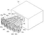
以下、本実施の形態におけるノズル支持アーム82の構成について図7乃至図10を用いて詳述する。ここで、図7は、図2等に示す液処理装置10における処理室20および6つのノズル支持アーム82p〜82uを示す斜視図であり、図8は、図7に示す各ノズル支持アーム82p〜82uの拡大斜視図である。また、図9は、図7等に示す各ノズル支持アーム82p〜82uを、これらのノズル支持アーム82p〜82uの後方から処理室20に向かって見たときの構成を示す図であり、図10は、図7等に示す各ノズル支持アーム82p〜82uの構成の詳細を示す側断面図である。   Hereinafter, the configuration of the nozzle support arm 82 in the present embodiment will be described in detail with reference to FIGS. Here, FIG. 7 is a perspective view showing the processing chamber 20 and the six nozzle support arms 82p to 82u in the liquid processing apparatus 10 shown in FIG. 2 and the like, and FIG. 8 shows the nozzle support arms 82p to 82p shown in FIG. It is an expansion perspective view of 82u. FIG. 9 is a diagram showing a configuration of the nozzle support arms 82p to 82u shown in FIG. 7 and the like when viewed from the rear of the nozzle support arms 82p to 82u toward the processing chamber 20. FIG. 8 is a side sectional view showing details of the configuration of each nozzle support arm 82p to 82u shown in FIG. 7 and the like.

図7に示すように、6つのノズル支持アーム82は、例えば純水供給用アーム82p、第1の薬液供給用アーム82q、N2ガス供給用アーム82r、第2の薬液供給用アーム82s、純水のミスト供給用アーム82tおよびIPA供給用アーム82uから構成されている。前述のように、これらのアーム82p〜82uの先端にはノズル82aが設けられている。このようにして、純水供給用アーム82pの先端に設けられたノズル82aからは純水がウエハWの上面に供給され、第1の薬液供給用アーム82qの先端に設けられたノズル82aからは第1の薬液(具体的には、例えば酸性の薬液)がウエハWの上面に供給され、N2ガス供給用アーム82rの先端に設けられたノズル82aからはN2ガスがウエハの上面に供給されるようになっている。また、第2の薬液供給用アーム82sの先端に設けられたノズル82aからは第2の薬液(具体的には、例えばアルカリ性の薬液)がウエハWの上面に供給され、純水のミスト供給用アーム82tの先端に設けられたノズル82aからは純水のミストがウエハWの上面に供給され、IPA供給用アーム82uの先端に設けられたノズル82aからはIPAがウエハWの上面に供給されるようになっている。   As shown in FIG. 7, the six nozzle support arms 82 include, for example, a pure water supply arm 82p, a first chemical solution supply arm 82q, an N2 gas supply arm 82r, a second chemical solution supply arm 82s, and pure water. Mist supply arm 82t and IPA supply arm 82u. As described above, the nozzles 82a are provided at the tips of these arms 82p to 82u. In this way, pure water is supplied to the upper surface of the wafer W from the nozzle 82a provided at the tip of the pure water supply arm 82p, and from the nozzle 82a provided at the tip of the first chemical solution supply arm 82q. A first chemical solution (specifically, for example, an acidic chemical solution) is supplied to the upper surface of the wafer W, and N2 gas is supplied to the upper surface of the wafer from a nozzle 82a provided at the tip of the N2 gas supply arm 82r. It is like that. A second chemical solution (specifically, for example, an alkaline chemical solution) is supplied to the upper surface of the wafer W from a nozzle 82a provided at the tip of the second chemical solution supply arm 82s, and is used for supplying pure water mist. Pure water mist is supplied to the upper surface of the wafer W from the nozzle 82a provided at the tip of the arm 82t, and IPA is supplied to the upper surface of the wafer W from the nozzle 82a provided at the tip of the IPA supply arm 82u. It is like that.

図8および図10に示すように、各ノズル支持アーム82には、当該ノズル支持アーム82を直進運動させるためのアーム駆動機構85が設けられている。アーム駆動機構85は、ベース部材85dに取り付けられ正逆両方向に回転するモータ85aと、モータ85aに対向するようベース部材85dに取り付けられたプーリ85bと、モータ85aおよびプーリ85bに巻き掛けられた循環ベルト85cと、循環ベルト85cに取り付けられたベルト取付部材85eとを有している。ここで、ベルト取付部材85eは、ノズル支持アーム82を支持するアーム支持部84の下部に取り付けられており、ベルト取付部材85eおよびアーム支持部84は一体的に移動するようになっている。そして、このようなアーム駆動機構85において、モータ85aが回転することにより循環ベルト85cが図10における右方向または左方向に移動し、この循環ベルト85cに取り付けられたベルト取付部材85eが図10における右方向または左方向に移動することにより、アーム支持部84が図10における左右方向に直進運動を行うようになる。このようにして、アーム支持部84に支持されるノズル支持アーム82も図10における左右方向に直進運動を行う。   As shown in FIGS. 8 and 10, each nozzle support arm 82 is provided with an arm drive mechanism 85 for causing the nozzle support arm 82 to linearly move. The arm drive mechanism 85 includes a motor 85a attached to the base member 85d and rotating in both forward and reverse directions, a pulley 85b attached to the base member 85d so as to face the motor 85a, and a circulation wound around the motor 85a and the pulley 85b. A belt 85c and a belt attachment member 85e attached to the circulation belt 85c are provided. Here, the belt attachment member 85e is attached to the lower part of the arm support part 84 which supports the nozzle support arm 82, and the belt attachment member 85e and the arm support part 84 move integrally. In such an arm drive mechanism 85, when the motor 85a rotates, the circulation belt 85c moves in the right direction or left direction in FIG. 10, and the belt attachment member 85e attached to the circulation belt 85c in FIG. By moving in the right direction or the left direction, the arm support portion 84 moves straight in the left-right direction in FIG. In this manner, the nozzle support arm 82 supported by the arm support portion 84 also moves straight in the left-right direction in FIG.

本実施の形態の液処理装置10においては、アーム駆動機構85が処理室20の外部に設けられていることにより、このアーム駆動機構85から発生するゴミ等が処理室20内に入ってしまうことを抑制することができる。また、処理室20内の雰囲気がアーム駆動機構85に到達してしまうことを抑制することができる。   In the liquid processing apparatus 10 of the present embodiment, because the arm driving mechanism 85 is provided outside the processing chamber 20, dust generated from the arm driving mechanism 85 enters the processing chamber 20. Can be suppressed. In addition, it is possible to suppress the atmosphere in the processing chamber 20 from reaching the arm driving mechanism 85.

また、図9に示すように、上述した6つのアーム82p〜82uのうち、純水供給用アーム82p、N2ガス供給用アーム82rおよび純水のミスト供給用アーム82tは同じ高さレベルに設置されている。より具体的には、図9において、これらのアーム82p、82r、82tは、図9における二点鎖線Aで囲まれる領域の高さレベルに設置されている。一方、上述した6つのアーム82p〜82uのうち、第1の薬液供給用アーム82q、第2の薬液供給用アーム82sおよびIPA供給用アーム82uも同じ高さレベルに設置されている。より具体的には、図9において、これらのアーム82q、82s、82uは、図9における二点鎖線Bで囲まれる領域の高さレベルに設置されている。そして、図9に示すように、純水供給用アーム82p、N2ガス供給用アーム82rおよび純水のミスト供給用アーム82tは、それぞれ、第1の薬液供給用アーム82q、第2の薬液供給用アーム82sおよびIPA供給用アーム82uよりも高い位置に設置されている。   Also, as shown in FIG. 9, among the six arms 82p to 82u described above, the pure water supply arm 82p, the N2 gas supply arm 82r, and the pure water mist supply arm 82t are installed at the same height level. ing. More specifically, in FIG. 9, these arms 82p, 82r, and 82t are installed at the height level of the region surrounded by the two-dot chain line A in FIG. On the other hand, among the six arms 82p to 82u described above, the first chemical solution supply arm 82q, the second chemical solution supply arm 82s, and the IPA supply arm 82u are also installed at the same height level. More specifically, in FIG. 9, these arms 82q, 82s, and 82u are installed at the height level of the region surrounded by the two-dot chain line B in FIG. As shown in FIG. 9, the pure water supply arm 82p, the N 2 gas supply arm 82r, and the pure water mist supply arm 82t are respectively a first chemical liquid supply arm 82q and a second chemical liquid supply arm. It is installed at a position higher than the arm 82s and the IPA supply arm 82u.

また、本実施の形態の液処理装置10においては、高さレベルが互いに異なる複数のアーム82p〜82uが同時に処理室20内に進出したときにアーム同士が衝突または干渉しないようになっている。   Further, in the liquid processing apparatus 10 according to the present embodiment, when a plurality of arms 82p to 82u having different height levels advance into the processing chamber 20 at the same time, the arms do not collide or interfere with each other.

本実施の形態の液処理装置10においては、ウエハWの乾燥処理を行うにあたり、処理室20内において保持部21により保持されたウエハWに対してIPAを供給した後、このウエハWにおけるIPAが供給された箇所にN2ガスを供給するようになっている。このような場合、N2ガス供給用アーム82rおよびIPA供給用アーム82uが同時に処理室20内に進出する。ここで、前述のように、N2ガス供給用アーム82rおよびIPA供給用アーム82uは互いに高さレベルが異なるようになっている。より詳細には、N2ガス供給用アーム82rは図9における二点鎖線Aで囲まれる領域の高さレベルに設置されているのに対し、IPA供給用アーム82uは図9における二点鎖線Bで囲まれる領域の高さレベルに設置されている。   In the liquid processing apparatus 10 of the present embodiment, when performing the drying process of the wafer W, the IPA is supplied to the wafer W held by the holding unit 21 in the processing chamber 20, and then the IPA on the wafer W is changed. N2 gas is supplied to the supplied location. In such a case, the N 2 gas supply arm 82r and the IPA supply arm 82u advance into the processing chamber 20 at the same time. Here, as described above, the N2 gas supply arm 82r and the IPA supply arm 82u have different height levels. More specifically, the N2 gas supply arm 82r is installed at the height level of the region surrounded by the two-dot chain line A in FIG. 9, whereas the IPA supply arm 82u is shown by the two-dot chain line B in FIG. It is installed at the height level of the enclosed area.

そして、処理室20内において、IPA供給用アーム82uに設けられたノズル82aからIPAが噴射されるウエハW上の領域に対して、N2ガス供給用アーム82rに設けられたノズル82aからN2が噴射されるウエハW上の領域が後を追うように、これらのIPA供給用アーム82uおよびN2ガス供給用アーム82rを処理室20内で移動させる。この際に、N2ガス供給用アーム82rおよびIPA供給用アーム82uは互いに高さレベルが異なるようになっているので、これらのアーム82r、82uが互いに干渉することはない。このようにして、処理室20内に進出したIPA供給用アーム82uに設けられたノズル82aからウエハWに対してIPAを供給した後に、このウエハWにおけるIPAが供給された箇所に対して処理室20内に進出したN2ガス供給用アーム82rに設けられたノズル82aからN2ガスを供給することができるようになる。   In the processing chamber 20, N2 is ejected from the nozzle 82a provided on the N2 gas supply arm 82r to the region on the wafer W where IPA is ejected from the nozzle 82a provided on the IPA supply arm 82u. The IPA supply arm 82u and the N 2 gas supply arm 82r are moved in the processing chamber 20 so that the region on the wafer W to be followed follows. At this time, since the N2 gas supply arm 82r and the IPA supply arm 82u have different height levels, the arms 82r and 82u do not interfere with each other. In this way, after IPA is supplied to the wafer W from the nozzle 82a provided in the IPA supply arm 82u that has advanced into the processing chamber 20, the processing chamber is supplied to the portion of the wafer W to which IPA is supplied. The N2 gas can be supplied from the nozzle 82a provided in the N2 gas supply arm 82r that has advanced into the nozzle 20.

また、他の例としては、ウエハWに対して酸性やアルカリ性の薬液により処理を行うにあたり、処理室20内において保持部21により保持されたウエハWに対して薬液を供給した後に中断することなく引き続きこのウエハWに純水を供給してリンス処理を行うようになっている。このような場合、第1の薬液供給用アーム82q(または第2の薬液供給用アーム82s)および純水供給用アーム82pが同時に処理室20内に進出する。ここで、前述のように、純水供給用アーム82pおよび第1の薬液供給用アーム82q(または第2の薬液供給用アーム82s)は互いに高さレベルが異なるようになっている。より詳細には、純水供給用アーム82pは図9における二点鎖線Aで囲まれる領域の高さレベルに設置されているのに対し、第1の薬液供給用アーム82q(または第2の薬液供給用アーム82s)は図9における二点鎖線Bで囲まれる領域の高さレベルに設置されている。   As another example, when the wafer W is processed with an acidic or alkaline chemical solution, the chemical solution is supplied to the wafer W held by the holding unit 21 in the processing chamber 20 without interruption. Subsequently, pure water is supplied to the wafer W to perform a rinsing process. In such a case, the first chemical solution supply arm 82q (or the second chemical solution supply arm 82s) and the pure water supply arm 82p simultaneously advance into the processing chamber 20. Here, as described above, the pure water supply arm 82p and the first chemical liquid supply arm 82q (or the second chemical liquid supply arm 82s) have different height levels. More specifically, the pure water supply arm 82p is installed at the height level of the region surrounded by the two-dot chain line A in FIG. 9, while the first chemical solution supply arm 82q (or the second chemical solution). The supply arm 82s) is installed at a height level in a region surrounded by a two-dot chain line B in FIG.

そして、処理室20内において、保持部21により保持されたウエハWに対して薬液を供給した後に中断することなく引き続きこのウエハWに純水を供給するように、純水供給用アーム82pおよび第1の薬液供給用アーム82q(または第2の薬液供給用アーム82s)を処理室20内で移動させる。この際に、純水供給用アーム82pおよび第1の薬液供給用アーム82q(または第2の薬液供給用アーム82s)は互いに高さレベルが異なるようになっているので、これらのアーム82p、82q(またはアーム82p、82s)が互いに干渉することはない。このようにして、処理室20内に進出した第1の薬液供給用アーム82q(または第2の薬液供給用アーム82s)に設けられたノズル82aからウエハWに対して薬液を供給した後に、処理室20内に進出した純水供給用アーム82pに設けられたノズル82aから純水を中断することなく引き続き供給してリンス処理を行うことができるようになる。   Then, in the processing chamber 20, the pure water supply arm 82 p and the second water supply arm 82 p and the second water supply so that the pure water is continuously supplied to the wafer W without interruption after the chemical liquid is supplied to the wafer W held by the holding unit 21. One chemical solution supply arm 82q (or second chemical solution supply arm 82s) is moved in the processing chamber 20. At this time, since the pure water supply arm 82p and the first chemical liquid supply arm 82q (or the second chemical liquid supply arm 82s) have different height levels, these arms 82p, 82q are different from each other. (Or arms 82p, 82s) do not interfere with each other. In this way, after supplying the chemical solution to the wafer W from the nozzle 82a provided in the first chemical solution supply arm 82q (or the second chemical solution supply arm 82s) that has advanced into the processing chamber 20, the processing is performed. The pure water can be continuously supplied from the nozzle 82a provided in the pure water supply arm 82p that has advanced into the chamber 20 without being interrupted to perform the rinsing process.

図10に示すように、各アーム82p〜82uは二重配管構造となっている。より詳細には、各アーム82p〜82uは内部配管82bおよび外部配管82cから構成されている。内部配管82bはノズル82aに連通しており、この内部配管82bからノズル82aに流体が送られるようになっている。内部配管82bは例えばフッ素系樹脂から構成されている。また、内部配管82bは外部配管82cに覆われるようになっており、この外部配管82cは例えばステンレス鋼パイプにフッ素系樹脂をコーティングしたものからなる。   As shown in FIG. 10, each arm 82p-82u has a double piping structure. In more detail, each arm 82p-82u is comprised from the internal piping 82b and the external piping 82c. The internal pipe 82b communicates with the nozzle 82a, and fluid is sent from the internal pipe 82b to the nozzle 82a. The internal pipe 82b is made of, for example, a fluorine resin. The internal pipe 82b is covered with an external pipe 82c, and the external pipe 82c is made of, for example, a stainless steel pipe coated with a fluorine resin.

また、図8および図10等に示すように、各アーム82p〜82uの後端側におけるこれらのアーム82p〜82uの外側には、各内部配管82bに連通する渦巻き形状配管83p〜83uがそれぞれ設けられている。各渦巻き形状配管83p〜83uは可撓性材料から形成されている。具体的には、各渦巻き形状配管83p〜83uは例えばフッ素系樹脂等のチューブが渦巻き形状に曲げられたものから形成されている。図7、図8および図10に示すように、各渦巻き形状配管83p〜83uは、対応するアーム82p〜82uが退避位置にあるときに、これらのアーム82p〜82uの延びる方向に直交する平面(すなわち、鉛直方向に延びる平面)上で渦巻き形状となるよう構成されている。そして、各渦巻き形状配管83p〜83uに薬液等の流体が送られることにより、各アーム82p〜82uの内部に設けられた内部配管82bを経てノズル82aから流体が下方に噴射されるようになっている。また、各渦巻き形状配管83p〜83uは可撓性材料から形成されているため、対応するアーム82p〜82uが処理室20内に進出した場合には、渦巻き形状配管83p〜83uは図8に示すような渦巻き形状から変形して円錐螺旋形状(先端が徐々に細くなるような螺旋形状)となる。   Further, as shown in FIGS. 8 and 10, etc., spiral pipes 83p to 83u communicating with the internal pipes 82b are provided outside the arms 82p to 82u on the rear end sides of the arms 82p to 82u, respectively. It has been. Each spiral pipe 83p-83u is formed from a flexible material. Specifically, each of the spiral-shaped pipes 83p to 83u is formed of, for example, a tube made of fluorine resin or the like bent into a spiral shape. As shown in FIGS. 7, 8, and 10, the spiral-shaped pipes 83 p to 83 u each have a plane orthogonal to the extending direction of the arms 82 p to 82 u when the corresponding arms 82 p to 82 u are in the retracted position ( That is, a spiral shape is formed on a plane extending in the vertical direction. Then, when a fluid such as a chemical solution is sent to each of the spiral pipes 83p to 83u, the fluid is jetted downward from the nozzle 82a via the internal pipe 82b provided inside each arm 82p to 82u. Yes. Moreover, since each spiral-shaped piping 83p-83u is formed from the flexible material, when the corresponding arm 82p-82u advances into the process chamber 20, spiral-shaped piping 83p-83u is shown in FIG. By deforming from such a spiral shape, it becomes a conical spiral shape (a spiral shape whose tip gradually narrows).

また、本実施の形態の液処理装置10においては、各アーム82p〜82uは、当該アーム82p〜82uの移動方向に沿った長手方向軸を中心として回転可能となっている。具体的には、図8に示すように、各アーム82p〜82uには回転機構86が設けられており、この回転機構86により各アーム82p〜82uは図8における矢印方向に回転するようになっている。各アーム82p〜82uを回転させることにより、ノズル82aの向きを図10に示すような下向きから他の方向に変えることができるようになる。また、各渦巻き形状配管83p〜83uは渦巻き形状となっているとともに可撓性材料から形成されているため、回転機構86により各アーム82p〜82uを回転させた場合でも、対応する渦巻き形状配管83p〜83uはアーム82p〜82uの回転に合わせてスムーズに変形するようになり、アーム82p〜82uの回転が各渦巻き形状配管83p〜83uにより妨げられることはない。   Moreover, in the liquid processing apparatus 10 of this Embodiment, each arm 82p-82u can rotate centering | focusing on the longitudinal direction axis | shaft along the moving direction of the said arms 82p-82u. Specifically, as shown in FIG. 8, each arm 82p to 82u is provided with a rotation mechanism 86, and the arm 82p to 82u is rotated in the direction of the arrow in FIG. ing. By rotating the arms 82p to 82u, the direction of the nozzle 82a can be changed from the downward direction as shown in FIG. 10 to another direction. In addition, since each of the spiral-shaped pipes 83p to 83u has a spiral shape and is formed of a flexible material, even when each of the arms 82p to 82u is rotated by the rotation mechanism 86, the corresponding spiral-shaped pipe 83p. ˜83u is smoothly deformed in accordance with the rotation of the arms 82p to 82u, and the rotation of the arms 82p to 82u is not hindered by the spiral pipes 83p to 83u.

回転機構86は、保持部21に保持されたウエハWに対してノズル82aにより流体を供給する際に、このノズル82aを支持するアーム82p〜82uを選択的に長手方向軸を中心として回転させるようになっている。具体的には、保持部21に保持されたウエハWの周縁部にノズル82aが近づくと、このノズル82aの向きは下向きから斜めに傾斜するようアーム82p〜82uが回転するようになっている。このことにより、保持部21に保持されたウエハWの周縁部において、ノズル82aから斜め下方に流体が噴射されることによって、ノズル82aからウエハWに供給された流体、具体的には薬液等の液体について、ウエハWの周縁部上での液ハネを抑制することができるようになる。このように、回転機構86は、ノズル82aがウエハWの中心に位置する場合とノズル82aがウエハWの周縁部に位置する場合とで、ノズル82aの向きを変えることができるようになっている。   The rotation mechanism 86 selectively rotates the arms 82p to 82u supporting the nozzle 82a about the longitudinal axis when supplying the fluid to the wafer W held by the holding unit 21 by the nozzle 82a. It has become. Specifically, when the nozzle 82a approaches the peripheral portion of the wafer W held by the holding unit 21, the arms 82p to 82u rotate so that the direction of the nozzle 82a is inclined obliquely from the downward direction. As a result, fluid is ejected obliquely downward from the nozzle 82a at the peripheral edge of the wafer W held by the holding unit 21, so that the fluid supplied from the nozzle 82a to the wafer W, specifically, a chemical solution, etc. With respect to the liquid, liquid splash on the peripheral edge of the wafer W can be suppressed. As described above, the rotation mechanism 86 can change the direction of the nozzle 82a between the case where the nozzle 82a is located at the center of the wafer W and the case where the nozzle 82a is located at the peripheral edge of the wafer W. .

また、回転機構86は、各アーム82p〜82uが進出位置と退避位置との間で移動する際に、ノズル82aが下向き以外の向き、具体的には例えば上向きとなるよう、長手方向軸を中心としてアーム82p〜82uを回転させるようになっている。このことにより、アーム82p〜82uを移動させる際にノズル82aから薬液等の液体がボタ落ちしてしまうことを防止することができる。   Further, the rotation mechanism 86 is centered on the longitudinal axis so that the nozzle 82a is oriented in a direction other than downward, specifically, for example, upward when each of the arms 82p to 82u moves between the advanced position and the retracted position. As a result, the arms 82p to 82u are rotated. Accordingly, it is possible to prevent liquid such as a chemical from dropping from the nozzle 82a when the arms 82p to 82u are moved.

また、図7および図10に示すように、各アーム82p〜82uには、これらのアーム82p〜82uの洗浄を行うためのアーム洗浄部88がアーム82p〜82u毎に位置固定で設けられている。各アーム洗浄部88は、それぞれ対応するアーム82p〜82uが移動する際に当該アーム82p〜82uの洗浄を行うようになっている。このような各アーム洗浄部88による各アーム82p〜82uの洗浄のタイミングは自由に設定できるようになっており、具体的には、各アーム82p〜82uの洗浄は例えば処理毎に、または一日一回、あるいは月に一回行われるようになっている。   As shown in FIGS. 7 and 10, each arm 82p to 82u is provided with an arm cleaning section 88 for cleaning the arms 82p to 82u in a fixed position for each arm 82p to 82u. . Each arm cleaning unit 88 is configured to clean the arms 82p to 82u when the corresponding arms 82p to 82u move. The timing of cleaning the arms 82p to 82u by the arm cleaning section 88 can be set freely. Specifically, the cleaning of the arms 82p to 82u is performed, for example, for each process or for one day. Once a month or once a month.

アーム洗浄部88の構成の詳細について図10を用いて説明する。図10に示すように、アーム洗浄部88には、ノズル支持アーム82(82p〜82u)が通過する貫通穴が水平方向(図10における左右方向)に延びるよう設けられている。この貫通穴の断面は、ノズル支持アーム82の断面よりもわずかに大きくなっている。また、この貫通穴には、洗浄液が収容される収容部分88aが設けられている。また、収容部分88aには洗浄液供給管88bが接続されており、洗浄液供給管88bから収容部分88aに洗浄液が供給されるようになっている。収容部分88aに洗浄液が供給されると、この収容部分88a内でノズル支持アーム82の外周面上に液膜が張られるようになる。そして、アーム洗浄部88において、収容部分88aに収容された洗浄液にノズル支持アーム82(82p〜82u)の一部が接触しながら当該ノズル支持アーム82が移動することによりノズル支持アーム82の洗浄が行われるようになっている。   Details of the configuration of the arm cleaning unit 88 will be described with reference to FIG. As shown in FIG. 10, the arm cleaning section 88 is provided with a through hole through which the nozzle support arm 82 (82p to 82u) passes so as to extend in the horizontal direction (left and right direction in FIG. 10). The cross section of the through hole is slightly larger than the cross section of the nozzle support arm 82. The through hole is provided with a storage portion 88a for storing the cleaning liquid. Further, a cleaning liquid supply pipe 88b is connected to the storage portion 88a, and the cleaning liquid is supplied from the cleaning liquid supply pipe 88b to the storage portion 88a. When the cleaning liquid is supplied to the storage portion 88a, a liquid film is stretched on the outer peripheral surface of the nozzle support arm 82 in the storage portion 88a. In the arm cleaning unit 88, the nozzle support arm 82 moves while the nozzle support arm 82 (82p to 82u) is in contact with a part of the cleaning liquid stored in the storage portion 88a, so that the nozzle support arm 82 is cleaned. To be done.

また、アーム洗浄部88において、ノズル支持アーム82の移動方向(図10における左右方向)における収容部分88aよりも処理室20に近い前方位置および収容部分88aよりも処理室20から遠い後方位置にはそれぞれ吸引機構88c、88dが設けられている。これらの吸引機構88c、88dは、収容部分88aに収容された洗浄液がこの収容部分88aから外部に漏れたときに漏れた分の洗浄液を吸引して排液するようになっている。なお、吸引機構は、必ずしもノズル支持アーム82の移動方向における収容部分88aよりも前方位置および後方位置の両方に設ける必要はなく、代わりに、ノズル支持アーム82の移動方向における収容部分88aよりも前方位置または後方位置のうちいずれか一方にのみ吸引機構が設けられるようになっていてもよい。   Further, in the arm cleaning unit 88, the nozzle support arm 82 is moved in the moving direction (left and right direction in FIG. 10) at a front position closer to the processing chamber 20 than the storage portion 88a and a rear position farther from the processing chamber 20 than the storage portion 88a. Suction mechanisms 88c and 88d are provided, respectively. These suction mechanisms 88c and 88d are adapted to suck and drain the amount of the cleaning liquid leaked when the cleaning liquid stored in the storage portion 88a leaks from the storage portion 88a to the outside. The suction mechanism is not necessarily provided at both the front position and the rear position with respect to the accommodating portion 88a in the moving direction of the nozzle support arm 82. Instead, the suction mechanism is located in front of the accommodating portion 88a in the moving direction of the nozzle support arm 82. The suction mechanism may be provided only in one of the position and the rear position.

また、吸引機構88c、88dは、ノズル支持アーム82が洗浄された後に、このノズル支持アーム82に付着した液滴を吸引することにより、ノズル支持アーム82の乾燥を行うようになっている。   Further, the suction mechanisms 88c and 88d are configured to dry the nozzle support arm 82 by sucking the droplets attached to the nozzle support arm 82 after the nozzle support arm 82 has been cleaned.

また、アーム洗浄部88において、ノズル支持アーム82の移動方向における収容部分88aよりも後方位置には、ノズル支持アーム82の内部配管82bに残留した薬液等の液体を排出するための排液部分88eが設けられている。また、排液部分88eにはドレン管88fが接続されており、排液部分88eに送られた液体はドレン管88fにより排出されるようになっている。そして、ノズル82aが排液部分88eの真上に位置するようノズル支持アーム82が移動して、ノズル支持アーム82の内部配管82bに残留した薬液等の液体がノズル82aから排液部分88eに吐出されるようになっている。このような排液部分88eが設けられていることにより、ウエハWの液処理が終了した後、ノズル支持アーム82の内部配管82bに液体が残留してしまった場合でも、このノズル支持アーム82に設けられたノズル82aを用いて次の液処理を行う際に、内部配管82bに残留した液体を予めこの内部配管82bから排出することができるようになる。とりわけ、ウエハWに高温の薬液等をノズル82aから供給するときには、ノズル支持アーム82の内部配管82bに残留している液体は冷めている場合が多いため、この残留している冷めた液体を排液部分88eにより予め内部配管82bから排出することが望ましい。   Further, in the arm cleaning unit 88, a drainage portion 88e for discharging a liquid such as a chemical solution remaining in the internal pipe 82b of the nozzle support arm 82 at a position behind the housing portion 88a in the moving direction of the nozzle support arm 82. Is provided. In addition, a drain pipe 88f is connected to the drainage portion 88e, and the liquid sent to the drainage portion 88e is discharged by the drain pipe 88f. Then, the nozzle support arm 82 moves so that the nozzle 82a is positioned directly above the drainage portion 88e, and liquid such as a chemical solution remaining in the internal pipe 82b of the nozzle support arm 82 is discharged from the nozzle 82a to the drainage portion 88e. It has come to be. By providing such a drainage portion 88e, even if liquid remains in the internal pipe 82b of the nozzle support arm 82 after the liquid processing of the wafer W is completed, the nozzle support arm 82 is provided with the liquid discharge portion 88e. When performing the next liquid treatment using the provided nozzle 82a, the liquid remaining in the internal pipe 82b can be discharged from the internal pipe 82b in advance. In particular, when a high-temperature chemical solution or the like is supplied to the wafer W from the nozzle 82a, the liquid remaining in the internal pipe 82b of the nozzle support arm 82 is often cooled, so that the remaining cooled liquid is discharged. It is desirable to discharge from the internal pipe 82b in advance by the liquid portion 88e.

なお、排液部分88eは、ノズル支持アーム82の移動方向における収容部分88aよりも後方位置ではなく収容部分88aよりも前方位置に設けられていてもよい。この場合でも、ノズル82aが排液部分88eの真上に位置するようノズル支持アーム82が移動し、ノズル82aから薬液を吐出することにより、ノズル支持アーム82の内部配管82bに残留した薬液等の液体がノズル82aから排液部分88eに送られるようになる。   In addition, the drainage part 88e may be provided in the position ahead rather than the accommodating part 88a rather than the back position rather than the accommodating part 88a in the moving direction of the nozzle support arm 82. Even in this case, the nozzle support arm 82 moves so that the nozzle 82a is located immediately above the drainage portion 88e, and the chemical liquid remaining in the internal pipe 82b of the nozzle support arm 82 is discharged by discharging the chemical liquid from the nozzle 82a. The liquid is sent from the nozzle 82a to the drainage portion 88e.

図7および図10に示すように、各アーム82p〜82uに対応する各アーム洗浄部88は、処理室20とアーム待機部80との間に設けられた壁90の外側に取り付けられるようになっている。このため、各アーム洗浄部88はカップ外周筒50の外側に設けられるようになる。なお、各アーム洗浄部88は壁90の外側に取り付けられる代わりに壁90の内側に取り付けられるようになっていてもよい。この場合には、各アーム洗浄部88は、回転カップ40とアーム待機部80との間の領域に位置するようになる。   As shown in FIGS. 7 and 10, each arm cleaning unit 88 corresponding to each arm 82 p to 82 u is attached to the outside of the wall 90 provided between the processing chamber 20 and the arm standby unit 80. ing. For this reason, each arm washing | cleaning part 88 comes to be provided in the outer side of the cup outer periphery cylinder 50. FIG. Each arm cleaning unit 88 may be attached to the inside of the wall 90 instead of being attached to the outside of the wall 90. In this case, each arm cleaning unit 88 is located in a region between the rotary cup 40 and the arm standby unit 80.

本実施の形態の液処理装置10においては、アーム洗浄部88はノズル支持アーム82の全体を洗浄するようになっていてもよく、あるいはノズル支持アーム82の一部分のみを洗浄するようになっていてもよい。また、アーム洗浄部88はノズル支持アーム82の全周を洗浄するようになっているが、このことに限定されることはない。   In the liquid processing apparatus 10 of the present embodiment, the arm cleaning unit 88 may clean the entire nozzle support arm 82 or only a part of the nozzle support arm 82. Also good. The arm cleaning unit 88 is configured to clean the entire circumference of the nozzle support arm 82, but is not limited to this.

また、本実施の形態の液処理装置10においては、図2や図10に示すように、各アーム82p〜82uは、アーム待機部80で待機しているときに、処理室20とアーム待機部80との間に設けられた壁90のアーム洗浄部88の開口88pを塞ぐようになっている。このことにより、各アーム82p〜82uは、壁90のアーム洗浄部88の開口88pを塞ぐ蓋として機能するようになり、処理室20内の領域とアーム待機部80の領域とを隔離することができるようになる。   Moreover, in the liquid processing apparatus 10 of this Embodiment, as shown in FIG.2 and FIG.10, when each arm 82p-82u is waiting in the arm waiting part 80, the process chamber 20 and an arm waiting part 80, the opening 88p of the arm cleaning portion 88 of the wall 90 provided between the wall 90 and the wall 80 is closed. As a result, each arm 82p to 82u functions as a lid for closing the opening 88p of the arm cleaning unit 88 of the wall 90, and the region in the processing chamber 20 and the region of the arm standby unit 80 can be isolated. become able to.

また、各アーム82p〜82uは、図5に示すような上方位置にあるカップ外周筒50の開口50mも塞ぐことができるようになっている。このことにより、カップ外周筒50内の領域とアーム待機部80の領域とを隔離することができるようになる。   Moreover, each arm 82p-82u can also block | close the opening 50m of the cup outer periphery cylinder 50 in an upper position as shown in FIG. As a result, the region in the cup outer peripheral cylinder 50 and the region of the arm standby portion 80 can be isolated.

次に、このような構成からなる液処理装置10の動作について説明する。   Next, the operation of the liquid processing apparatus 10 having such a configuration will be described.

まず、保持部21におけるリフトピンプレート22および処理液供給管28を図4に示す位置から上方に移動させることと、処理室20の開口94aに設けられたシャッター94をこの開口94aから退避させることにより開口94aを開くことを行う。そして、液処理装置10の外部からウエハWが搬送アーム104により開口94aを介して処理室20内に搬送され、このウエハWがリフトピンプレート22のリフトピン23上に載置され、その後、搬送アーム104は処理室20から退避する。この際に、カップ外周筒50は図4に示すような下方位置に位置している。また、各ノズル支持アーム82は処理室20から退避した退避位置に位置している。すなわち、各ノズル支持アーム82はアーム待機部80で待機している。また、FFU70から処理室20内にクリーンエア等のガスが常にダウンフローで送られ、このガスが排気部54により排気されることにより、処理室20内の雰囲気の置換が行われるようになっている。   First, the lift pin plate 22 and the processing liquid supply pipe 28 in the holding unit 21 are moved upward from the position shown in FIG. 4, and the shutter 94 provided in the opening 94a of the processing chamber 20 is retracted from the opening 94a. Opening 94a is performed. Then, the wafer W is transferred from the outside of the liquid processing apparatus 10 to the processing chamber 20 by the transfer arm 104 through the opening 94 a, and the wafer W is placed on the lift pins 23 of the lift pin plate 22. Is withdrawn from the processing chamber 20. At this time, the cup outer peripheral cylinder 50 is located at a lower position as shown in FIG. Further, each nozzle support arm 82 is located at a retracted position retracted from the processing chamber 20. That is, each nozzle support arm 82 is on standby at the arm standby unit 80. Further, a gas such as clean air is always sent in a down flow from the FFU 70 into the processing chamber 20, and this gas is exhausted by the exhaust unit 54, whereby the atmosphere in the processing chamber 20 is replaced. Yes.

次に、リフトピンプレート22および処理液供給管28を下方に移動させ、これらのリフトピンプレート22および処理液供給管28を図4に示すような下方位置に位置させる。この際に、保持プレート26に設けられた各保持部材25が、リフトピン23上のウエハWを支持し、このウエハWをリフトピン23からわずかに離間させる。   Next, the lift pin plate 22 and the processing liquid supply pipe 28 are moved downward, and the lift pin plate 22 and the processing liquid supply pipe 28 are positioned at a lower position as shown in FIG. At this time, each holding member 25 provided on the holding plate 26 supports the wafer W on the lift pins 23 and slightly separates the wafer W from the lift pins 23.

その後に、またはリフトピンプレート22の下降中に、カップ外周筒50に設けられた駆動機構50bにより、このカップ外周筒50を上方に移動させ、カップ外周筒50を図5に示すような上方位置に位置させる。そして、カップ外周筒50が上方位置に移動した後、アーム待機部80で待機している6つのノズル支持アーム82のうち一または複数のノズル支持アーム82が壁90のアーム洗浄部88の開口88pおよびカップ外周筒50の開口50mを介して処理室20内に進出する(図5の二点鎖線参照)。この際に、アーム駆動機構85によりノズル支持アーム82は直線運動を行う。   Thereafter, or while the lift pin plate 22 is being lowered, the cup outer peripheral cylinder 50 is moved upward by the drive mechanism 50b provided in the cup outer peripheral cylinder 50, and the cup outer peripheral cylinder 50 is moved to the upper position as shown in FIG. Position. Then, after the cup outer peripheral cylinder 50 moves to the upper position, one or a plurality of nozzle support arms 82 among the six nozzle support arms 82 waiting in the arm standby unit 80 are the openings 88p of the arm cleaning unit 88 of the wall 90. And it advances into the processing chamber 20 through the opening 50m of the cup outer cylinder 50 (refer to the two-dot chain line in FIG. 5). At this time, the nozzle driving arm 82 performs linear motion by the arm driving mechanism 85.

そして、保持部21における保持プレート26およびリフトピンプレート22を回転させる。このことにより、保持プレート26の各保持部材25により支持されているウエハWも回転する。   Then, the holding plate 26 and the lift pin plate 22 in the holding unit 21 are rotated. As a result, the wafer W supported by each holding member 25 of the holding plate 26 also rotates.

その後、まず、保持プレート26の各保持部材25により支持されているウエハWに対して酸性の薬液により処理を行い、その後引き続いてリンス処理を行う。具体的には、図5に示すような状態で、アーム待機部80で待機している6つのノズル支持アーム82のうち第1の薬液供給用アーム82qおよび純水供給用アーム82pがそれぞれ壁90のアーム洗浄部88の開口88pおよびカップ外周筒50の開口50mを介して処理室20内に同時に進出する。この際に、第1の薬液供給用アーム82qおよび純水供給用アーム82pは互いに高さレベルが異なるようになっているので、これらのアーム82q、82pが互いに干渉することはない。   Thereafter, first, the wafer W supported by each holding member 25 of the holding plate 26 is processed with an acidic chemical solution, and then a rinse process is performed. Specifically, in the state shown in FIG. 5, the first chemical supply arm 82q and the pure water supply arm 82p out of the six nozzle support arms 82 waiting in the arm standby section 80 are respectively the walls 90. The arm cleaning unit 88 advances simultaneously into the processing chamber 20 through the opening 88p of the arm cleaning section 88 and the opening 50m of the cup outer peripheral cylinder 50. At this time, since the first chemical liquid supply arm 82q and the pure water supply arm 82p have different height levels, the arms 82q and 82p do not interfere with each other.

そして、ウエハWが回転した状態で、処理室20内に進出した第1の薬液供給用アーム82qのノズル82aからウエハWの上面に酸性の薬液を供給する。また、この際に、ウエハWの下面(裏面)に向かって処理液供給管28から酸性の薬液を供給してもよい。このようにして、ウエハWの少なくとも上面に酸性の薬液が供給され、ウエハWの薬液処理が行われる。ウエハWに供給された酸性の薬液は、4つの処理液回収用タンク46a、46b、46c、46dのうち例えば第1処理液回収用タンク46aに送られて回収される。また、上述のような薬液処理が行われる際に、純水供給用アーム82pは、第1の薬液供給用アーム82qのノズル82aによる酸性の薬液の吐出位置からわずかに後退した位置に当該純水供給用アーム82pのノズル82aが位置するよう、処理室20内で待機している。ここで、純水供給用アーム82pが待機しているときに、ノズル82aが下向き以外の向き、具体的には例えば上向きとなるように純水供給用アーム82pを回転させておけば、薬液処理中において純水供給用アーム82pのノズル82aからのボタ落ちを防止することができる。   Then, an acidic chemical solution is supplied to the upper surface of the wafer W from the nozzle 82a of the first chemical solution supply arm 82q that has advanced into the processing chamber 20 while the wafer W is rotated. At this time, an acidic chemical solution may be supplied from the processing solution supply pipe 28 toward the lower surface (back surface) of the wafer W. In this way, the acidic chemical solution is supplied to at least the upper surface of the wafer W, and the chemical treatment of the wafer W is performed. The acidic chemical supplied to the wafer W is sent to, for example, the first processing liquid recovery tank 46a out of the four processing liquid recovery tanks 46a, 46b, 46c, and 46d and recovered. Further, when the above chemical solution treatment is performed, the pure water supply arm 82p is moved to a position slightly retracted from the acidic chemical solution discharge position by the nozzle 82a of the first chemical solution supply arm 82q. It waits in the processing chamber 20 so that the nozzle 82a of the supply arm 82p is positioned. Here, when the pure water supply arm 82p is waiting, if the pure water supply arm 82p is rotated so that the nozzle 82a is oriented in a direction other than downward, specifically, for example, upward, the chemical solution treatment is performed. It is possible to prevent dropping of the pure water supply arm 82p from the nozzle 82a.

そして、保持プレート26の各保持部材25により支持されているウエハWに対して酸性の薬液が供給された後に中断することなく引き続きこのウエハWに純水が供給される。具体的には、処理室20内に進出した第1の薬液供給用アーム82qに設けられたノズル82aからウエハWに対して酸性の薬液を供給した後に、処理室20内に進出した純水供給用アーム82pに設けられたノズル82aから純水を中断することなく引き続きウエハWに供給する。ウエハWに供給された純水は、4つの処理液回収用タンク46a、46b、46c、46dのうち例えば第3処理液回収用タンク46cに送られて回収される。このようにして、カップ外周筒50内でウエハWに対して酸性の薬液により処理が行われ、その後引き続いてリンス処理が行われるようになる。この際に、処理室20内において純水供給用アーム82pと第1の薬液供給用アーム82qは互いに高さレベルが異なっているのでこれらのアーム82p、82qが互いに干渉することはない。そして、ウエハWに対する酸性の薬液による処理およびリンス処理が終了すると、処理室20に進出した第1の薬液供給用アーム82qはこの処理室20から退避してアーム待機部80で待機するようになる。一方、純水供給用アーム82pは処理室20内に残ったままとなる。また、リンス処理が行われる間に、第2の薬液供給用アーム82sが壁90のアーム洗浄部88の開口88pおよびカップ外周筒50の開口50mを介して処理室20内に進出する。より詳細には、上述のようなリンス処理が行われる際に、第2の薬液供給用アーム82sは、純水供給用アーム82pのノズル82aによる純水の吐出位置からわずかに後退した位置に当該第2の薬液供給用アーム82sのノズル82aが位置するよう、処理室20内で待機している。   Then, after the acidic chemical solution is supplied to the wafer W supported by each holding member 25 of the holding plate 26, pure water is continuously supplied to the wafer W without interruption. Specifically, after supplying an acidic chemical to the wafer W from the nozzle 82a provided in the first chemical supply arm 82q that has advanced into the processing chamber 20, the pure water supply that has advanced into the processing chamber 20 is supplied. Pure water is continuously supplied to the wafer W from the nozzle 82a provided on the arm 82p without interruption. The pure water supplied to the wafer W is sent to, for example, the third processing liquid recovery tank 46c among the four processing liquid recovery tanks 46a, 46b, 46c, and 46d and recovered. In this manner, the wafer W is processed with the acidic chemical solution in the cup outer peripheral cylinder 50, and then the rinsing process is subsequently performed. At this time, since the pure water supply arm 82p and the first chemical liquid supply arm 82q are different from each other in the processing chamber 20, the arms 82p and 82q do not interfere with each other. When the treatment with the acidic chemical solution and the rinsing process on the wafer W are completed, the first chemical supply arm 82q that has advanced into the processing chamber 20 is retracted from the processing chamber 20 and waits at the arm standby unit 80. . On the other hand, the pure water supply arm 82 p remains in the processing chamber 20. Further, during the rinsing process, the second chemical liquid supply arm 82 s advances into the processing chamber 20 through the opening 88 p of the arm cleaning unit 88 of the wall 90 and the opening 50 m of the cup outer cylinder 50. More specifically, when the rinsing process as described above is performed, the second chemical liquid supply arm 82s is in a position slightly retracted from the pure water discharge position by the nozzle 82a of the pure water supply arm 82p. It waits in the processing chamber 20 so that the nozzle 82a of the 2nd chemical | medical solution supply arm 82s may be located.

その後、保持プレート26の各保持部材25により支持されているウエハWに対してアルカリ性の薬液により処理を行い、その後引き続いてリンス処理を行う。具体的には、処理室20内に進出している第2の薬液供給用アーム82sおよび純水供給用アーム82pにより、ウエハWに対してアルカリ性の薬液による処理およびリンス処理が行われる。この際に、第2の薬液供給用アーム82sおよび純水供給用アーム82pは互いに高さレベルが異なるようになっているので、これらのアーム82s、82pが互いに干渉することはない。   Thereafter, the wafer W supported by each holding member 25 of the holding plate 26 is treated with an alkaline chemical solution, and then rinsed. More specifically, the second chemical solution supply arm 82s and the pure water supply arm 82p that have advanced into the processing chamber 20 perform the treatment with the chemical solution and the rinsing process on the wafer W. At this time, since the second chemical liquid supply arm 82s and the pure water supply arm 82p have different height levels, the arms 82s and 82p do not interfere with each other.

具体的に説明すると、ウエハWが回転した状態で、処理室20内に進出した第2の薬液供給用アーム82sのノズル82aからウエハWの上面にアルカリ性の薬液を供給する。また、この際に、ウエハWの下面(裏面)に向かって処理液供給管28からアルカリ性の薬液を供給してもよい。このようにして、ウエハWの少なくとも上面にアルカリ性の薬液が供給され、ウエハWの薬液処理が行われる。ウエハWに供給されたアルカリ性の薬液は、4つの処理液回収用タンク46a、46b、46c、46dのうち例えば第2処理液回収用タンク46bに送られて回収される。また、上述のような薬液処理が行われる際に、純水供給用アーム82pは、第2の薬液供給用アーム82sのノズル82aによるアルカリ性の薬液の吐出位置からわずかに後退した位置に当該純水供給用アーム82pのノズル82aが位置するよう、処理室20内で待機している。   More specifically, an alkaline chemical solution is supplied to the upper surface of the wafer W from the nozzle 82a of the second chemical solution supply arm 82s that has advanced into the processing chamber 20 while the wafer W is rotated. At this time, an alkaline chemical may be supplied from the processing liquid supply pipe 28 toward the lower surface (back surface) of the wafer W. In this way, the alkaline chemical solution is supplied to at least the upper surface of the wafer W, and the chemical treatment of the wafer W is performed. The alkaline chemical liquid supplied to the wafer W is sent to, for example, the second processing liquid recovery tank 46b among the four processing liquid recovery tanks 46a, 46b, 46c, and 46d and recovered. Further, when the above chemical solution treatment is performed, the pure water supply arm 82p is moved to a position slightly retracted from the alkaline chemical solution discharge position by the nozzle 82a of the second chemical solution supply arm 82s. It waits in the processing chamber 20 so that the nozzle 82a of the supply arm 82p is positioned.

そして、保持プレート26の各保持部材25により支持されているウエハWに対してアルカリ性の薬液が供給された後に中断することなく引き続きこのウエハWに純水が供給される。具体的には、処理室20内に進出した第2の薬液供給用アーム82sに設けられたノズル82aからウエハWに対してアルカリ性の薬液を供給した後に、処理室20内に進出している純水供給用アーム82pに設けられたノズル82aから純水を中断することなく引き続きウエハWに供給する。ウエハWに供給された純水は、4つの処理液回収用タンク46a、46b、46c、46dのうち例えば第3処理液回収用タンク46cに送られて回収される。このようにして、カップ外周筒50内でウエハWに対してアルカリ性の薬液により処理が行われ、その後引き続いてリンス処理が行われるようになる。そして、ウエハWに対するアルカリ性の薬液による処理およびリンス処理が終了すると、処理室20に進出した第2の薬液供給用アーム82sおよび純水供給用アーム82pはこの処理室20から退避してアーム待機部80で待機するようになる。また、上述のようなリンス処理が行われる間に、IPA供給用アーム82uが壁90のアーム洗浄部88の開口88pおよびカップ外周筒50の開口50mを介して処理室20内に進出する。より詳細には、上述のようなリンス処理が行われる際に、IPA供給用アーム82uは、純水供給用アーム82pのノズル82aによる純水の吐出位置からわずかに後退した位置に当該IPA供給用アーム82uのノズル82aが位置するよう、処理室20内で待機している。   Then, after the alkaline chemical solution is supplied to the wafer W supported by the holding members 25 of the holding plate 26, pure water is continuously supplied to the wafer W without interruption. Specifically, after supplying an alkaline chemical liquid to the wafer W from the nozzle 82a provided in the second chemical liquid supply arm 82s that has advanced into the processing chamber 20, the pure liquid that has advanced into the processing chamber 20 is supplied. Pure water is continuously supplied to the wafer W from the nozzle 82a provided on the water supply arm 82p without interruption. The pure water supplied to the wafer W is sent to, for example, the third processing liquid recovery tank 46c among the four processing liquid recovery tanks 46a, 46b, 46c, and 46d and recovered. In this manner, the wafer W is processed with the alkaline chemical solution in the cup outer peripheral cylinder 50, and then the rinsing process is subsequently performed. When the processing with the alkaline chemical solution and the rinsing process for the wafer W are completed, the second chemical solution supply arm 82s and the pure water supply arm 82p that have advanced into the processing chamber 20 are retracted from the processing chamber 20 and the arm standby unit. Wait at 80. Further, while the rinsing process as described above is performed, the IPA supply arm 82u advances into the processing chamber 20 through the opening 88p of the arm cleaning unit 88 of the wall 90 and the opening 50m of the cup outer peripheral cylinder 50. More specifically, when the rinsing process as described above is performed, the IPA supply arm 82u is moved to a position slightly retracted from the pure water discharge position by the nozzle 82a of the pure water supply arm 82p. It waits in the processing chamber 20 so that the nozzle 82a of the arm 82u is located.

その後、保持プレート26の各保持部材25により支持されているウエハWに対してIPAにより乾燥処理が行われる。具体的には、アーム待機部80で待機している6つのノズル支持アーム82のうちN2ガス供給用アーム82rが壁90のアーム洗浄部88の開口88pおよびカップ外周筒50の開口50mを介して処理室20内に進出する。このようにして、処理室20内にN2ガス供給用アーム82rおよびIPA供給用アーム82uがそれぞれ進出した状態となる。この際に、N2ガス供給用アーム82rおよびIPA供給用アーム82uは互いに高さレベルが異なるようになっているので、これらのアーム82r、82uが互いに干渉することはない。   Thereafter, the wafer W supported by each holding member 25 of the holding plate 26 is dried by IPA. Specifically, among the six nozzle support arms 82 waiting in the arm standby section 80, the N2 gas supply arm 82r passes through the opening 88p of the arm cleaning section 88 of the wall 90 and the opening 50m of the cup outer cylinder 50. Advancing into the processing chamber 20. In this manner, the N 2 gas supply arm 82r and the IPA supply arm 82u are advanced into the processing chamber 20, respectively. At this time, since the N2 gas supply arm 82r and the IPA supply arm 82u have different height levels, the arms 82r and 82u do not interfere with each other.

そして、ウエハWが回転した状態で、処理室20内に進出したIPA供給用アーム82uに設けられたノズル82aからウエハWに対してIPAを供給した後に、このウエハWにおけるIPAが供給された箇所に対して処理室20内に進出したN2ガス供給用アーム82rに設けられたノズル82aからN2ガスを供給する。具体的には、処理室20内において、IPA供給用アーム82uに設けられたノズル82aによりウエハWの中心にIPAが供給される。その後、IPA供給用アーム82uがウエハWの中心から周縁部に移動し、IPAが供給された後のウエハW上の領域に対して、N2ガス供給用アーム82rに設けられたノズル82aによりガスが噴射されるウエハW上の領域が後を追うように、これらのIPA供給用アーム82uおよびN2ガス供給用アーム82rをウエハW上で移動させる。このようにして、ウエハWの表面において、IPAが供給された箇所にN2ガスがすぐに供給されるようになり、ウエハWの乾燥処理を適切に行うことができるようになる。なお、ウエハWに供給されたIPAは、4つの処理液回収用タンク46a、46b、46c、46dのうち例えば第4処理液回収用タンク46dに送られて回収される。ウエハWの乾燥処理が終了すると、処理室20に進出したIPA供給用アーム82uおよびN2ガス供給用アーム82rはこの処理室20から退避してアーム待機部80で待機するようになる。   Then, after the wafer W is rotated, the IPA is supplied to the wafer W from the nozzle 82a provided in the IPA supply arm 82u that has advanced into the processing chamber 20, and then the IPA is supplied to the wafer W. In contrast, N 2 gas is supplied from a nozzle 82 a provided in an N 2 gas supply arm 82 r that has advanced into the processing chamber 20. Specifically, in the processing chamber 20, IPA is supplied to the center of the wafer W by a nozzle 82a provided in the IPA supply arm 82u. Thereafter, the IPA supply arm 82u moves from the center of the wafer W to the peripheral portion, and gas is supplied to the region on the wafer W after the IPA is supplied by the nozzle 82a provided in the N2 gas supply arm 82r. The IPA supply arm 82u and the N 2 gas supply arm 82r are moved on the wafer W so that the region on the wafer W to be sprayed follows. In this way, the N 2 gas is immediately supplied to the location where the IPA is supplied on the surface of the wafer W, and the drying process of the wafer W can be performed appropriately. The IPA supplied to the wafer W is sent to, for example, the fourth processing liquid recovery tank 46d out of the four processing liquid recovery tanks 46a, 46b, 46c, and 46d and recovered. When the drying process of the wafer W is completed, the IPA supply arm 82u and the N 2 gas supply arm 82r that have advanced into the process chamber 20 are retracted from the process chamber 20 and wait in the arm standby unit 80.

ウエハの乾燥処理が終了すると、カップ外周筒50に設けられた駆動機構50bにより、このカップ外周筒50を下方に移動させ、カップ外周筒50を図4に示すような下方位置に位置させる。   When the wafer drying process is completed, the cup outer peripheral cylinder 50 is moved downward by the drive mechanism 50b provided in the cup outer peripheral cylinder 50, and the cup outer peripheral cylinder 50 is positioned at the lower position as shown in FIG.

その後、保持部21におけるリフトピンプレート22および処理液供給管28を図4に示す位置から上方に移動させる。この際に、保持プレート26の保持部材25により支持されたウエハWがリフトピンプレート22のリフトピン23上に受け渡される。次に、処理室20の開口94aに設けられたシャッター94をこの開口94aから退避させることにより開口94aを開き、液処理装置10の外部から開口94aを介して搬送アーム104を処理室20内に進出させ、この搬送アーム104によりリフトピンプレート22のリフトピン23上のウエハWを取り出す。搬送アーム104により取り出されたウエハWは液処理装置10の外部に搬送される。このようにして、一連のウエハWの液処理が完了する。   Thereafter, the lift pin plate 22 and the processing liquid supply pipe 28 in the holding unit 21 are moved upward from the positions shown in FIG. At this time, the wafer W supported by the holding member 25 of the holding plate 26 is transferred onto the lift pins 23 of the lift pin plate 22. Next, the opening 94a is opened by retracting the shutter 94 provided in the opening 94a of the processing chamber 20 from the opening 94a, and the transfer arm 104 is moved into the processing chamber 20 from the outside of the liquid processing apparatus 10 through the opening 94a. The wafer W on the lift pins 23 of the lift pin plate 22 is taken out by the transfer arm 104. The wafer W taken out by the transfer arm 104 is transferred to the outside of the liquid processing apparatus 10. In this way, a series of liquid processing of the wafer W is completed.

なお、各ノズル支持アーム82の洗浄は、ノズル支持アーム82が処理室20からアーム待機部80における退避位置に移動する際にアーム洗浄部88により行ってもよい。また、各ノズル支持アーム82の洗浄は、ウエハWに対する各処理後に行ってもよいし、あるいは定期的に行ってもよい。   The cleaning of each nozzle support arm 82 may be performed by the arm cleaning unit 88 when the nozzle support arm 82 moves from the processing chamber 20 to the retracted position in the arm standby unit 80. Further, the cleaning of each nozzle support arm 82 may be performed after each processing on the wafer W, or may be performed periodically.

以上のように本実施の形態の液処理装置10によれば、ノズル支持アーム82p〜82uは複数設けられており、ノズル支持アーム82p、82r、82tはノズル支持アーム82q、82s、82uと高さレベルが異なるようになっている。このため、2以上のノズル支持アーム82p〜82uが処理室20内に進出しても、処理室20内に進出した2以上のノズル支持アーム82p〜82u同士が互いに衝突してしまうことを防止することができる。   As described above, according to the liquid processing apparatus 10 of the present embodiment, a plurality of nozzle support arms 82p to 82u are provided, and the nozzle support arms 82p, 82r, and 82t are as high as the nozzle support arms 82q, 82s, and 82u. The levels are different. For this reason, even if two or more nozzle support arms 82p to 82u advance into the processing chamber 20, the two or more nozzle support arms 82p to 82u advanced into the processing chamber 20 are prevented from colliding with each other. be able to.

また、本実施の形態の液処理装置10においては、複数のノズル支持アーム82p〜82uが同時に処理室20内に進出することができるようになっている。   Further, in the liquid processing apparatus 10 of the present embodiment, a plurality of nozzle support arms 82p to 82u can advance into the processing chamber 20 at the same time.

具体的には、保持部21に保持されたウエハWに対してIPAを供給した後に当該ウエハWにおけるIPAが供給された箇所にN2ガスを供給する際に、IPA供給用アーム82uおよびN2ガス供給用アーム82rが同時に処理室20内に進出するようになっている。このことにより、ウエハWの表面において、IPAガスが供給された箇所にN2ガスがすぐに供給されるようになり、ウエハWの乾燥処理を適切に行うことができるようになる。   Specifically, when IPA is supplied to the wafer W held by the holding unit 21 and then N2 gas is supplied to a location where the IPA is supplied to the wafer W, the IPA supply arm 82u and the N2 gas supply are supplied. The arm 82r advances into the processing chamber 20 at the same time. As a result, the N2 gas is immediately supplied to the location where the IPA gas is supplied on the surface of the wafer W, and the wafer W can be appropriately dried.

また、保持部21に保持されたウエハWに対して酸性やアルカリ性の薬液を供給した後に引き続き当該ウエハWに純水を供給する際に、第1の薬液供給用アーム82q(または第2の薬液供給用アーム82s)および純水供給用アーム82pが同時に処理室20内に進出するようになっている。このことにより、ウエハWに対して薬液により処理を行った後にリンス処理を引き続いて行うことができるようになる。   In addition, when supplying pure water to the wafer W after supplying acidic or alkaline chemical liquid to the wafer W held by the holding unit 21, the first chemical liquid supply arm 82 q (or the second chemical liquid is used). The supply arm 82s) and the pure water supply arm 82p advance into the processing chamber 20 at the same time. As a result, after the wafer W is processed with the chemical solution, the rinsing process can be continuously performed.

また、保持部21に保持されたウエハWに対して純水を供給した後に引き続き当該ウエハWの乾燥処理を行う際に、純水供給用アーム82pおよびIPA供給用アーム82uが同時に処理室20内に進出するようになっている。このことにより、ウエハWに対してリンス処理を行った後に乾燥処理を引き続いて行うことができるようになる。   Further, when the wafer W held in the holding unit 21 is supplied with pure water and subsequently dried, the pure water supply arm 82p and the IPA supply arm 82u are simultaneously provided in the processing chamber 20. Has come to advance. As a result, after the rinsing process is performed on the wafer W, the drying process can be continuously performed.

なお、本実施の形態による液処理装置は、上記の態様に限定されるものではなく、様々の変更を加えることができる。例えば、処理室20内に進出したノズル支持アーム82のノズル82aおよび処理液供給管28によりウエハWの上面および下面の両方に処理液を供給する必要はなく、ノズル支持アーム82のノズル82aによりウエハWの上面のみに処理液を供給するようになっていてもよい。   In addition, the liquid processing apparatus according to the present embodiment is not limited to the above aspect, and various changes can be made. For example, it is not necessary to supply the processing liquid to both the upper surface and the lower surface of the wafer W by the nozzle 82 a of the nozzle support arm 82 that has advanced into the processing chamber 20 and the processing liquid supply pipe 28, and the wafer by the nozzle 82 a of the nozzle support arm 82. The processing liquid may be supplied only to the upper surface of W.

また、一本のノズル支持アーム82に対して複数のノズル82aが設けられるようになっていてもよい。   A plurality of nozzles 82 a may be provided for one nozzle support arm 82.

10 液処理装置
20 処理室
21 保持部
22 リフトピンプレート
23 リフトピン
24 ピストン機構
25 保持部材
25a 軸
25b 支持部分
25c 被押圧部材
25d バネ部材
26 保持プレート
26a 軸受け部
26b 軸受け孔
26c 内面壁
28 処理液供給管
28a ヘッド部分
29 処理液供給部
40 回転カップ
42 ドレインカップ
43 第1案内カップ
44 第2案内カップ
45 第3案内カップ
46a 第1処理液回収用タンク
46b 第2処理液回収用タンク
46c 第3処理液回収用タンク
46d 第4処理液回収用タンク
48 排気部
50 カップ外周筒
50a 支持部材
50b 駆動機構
50m 開口
51 ガイド部材
52 洗浄部
52a 貯留部分
54 排気部
56 排気部
58 排気部
60 シャッター
62 シャッター
70 FFU
80 アーム待機部
82 ノズル支持アーム
82a ノズル
82b 内部配管
82c 外部配管
82p 純水供給用アーム
82q 第1の薬液供給用アーム
82r N2ガス供給用アーム
82s 第2の薬液供給用アーム
82t 純水のミスト供給用アーム
82u IPA供給用アーム
83p〜83u 渦巻き形状配管
84 アーム支持部
85 アーム駆動機構
85a モータ
85b プーリ
85c 循環ベルト
85d ベース部材
85e ベルト取付部材
86 回転機構
88 アーム洗浄部
88a 収容部分
88b 洗浄液供給管
88c 吸引機構
88d 吸引機構
88e 排液部分
88f ドレン管
88p 開口
89 表面処理液供給部
90 壁
94 シャッター
94a 開口
101 載置台
102 搬送アーム
103 棚ユニット
104 搬送アーム
200 液処理装置
210 処理室
220 保持部
230 カップ
240 ノズル
241 アーム
242 アーム支持部
250 FFU
260 排気部
DESCRIPTION OF SYMBOLS 10 Liquid processing apparatus 20 Processing chamber 21 Holding part 22 Lift pin plate 23 Lift pin 24 Piston mechanism 25 Holding member 25a Shaft 25b Support part 25c Pressed member 25d Spring member 26 Holding plate 26a Bearing part 26b Bearing hole 26c Inner surface wall 28 Processing liquid supply pipe 28a Head portion 29 Treatment liquid supply unit 40 Rotating cup 42 Drain cup 43 First guide cup 44 Second guide cup 45 Third guide cup 46a First treatment liquid collection tank 46b Second treatment liquid collection tank 46c Third treatment liquid Recovery tank 46d Fourth treatment liquid recovery tank 48 Exhaust part 50 Cup outer peripheral cylinder 50a Support member 50b Drive mechanism 50m Opening 51 Guide member 52 Washing part 52a Storage part 54 Exhaust part 56 Exhaust part 58 Exhaust part 60 Shutter 62 Shutter 70 Shutter 70 FFU
80 Arm standby section 82 Nozzle support arm 82a Nozzle 82b Internal pipe 82c External pipe 82p Pure water supply arm 82q First chemical supply arm 82r N2 gas supply arm 82s Second chemical supply arm 82t Pure water mist supply Arm 82u IPA supply arm 83p to 83u Spiral pipe 84 Arm support 85 Arm drive mechanism 85a Motor 85b Pulley 85c Circulation belt 85d Base member 85e Belt mounting member 86 Rotating mechanism 88 Arm cleaning section 88a Housing portion 88b Cleaning liquid supply pipe 88c Suction mechanism 88d Suction mechanism 88e Drainage portion 88f Drain pipe 88p Opening 89 Surface treatment liquid supply unit 90 Wall 94 Shutter 94a Opening 101 Mounting table 102 Transfer arm 103 Shelf unit 104 Transfer arm 200 Liquid processing device 210 Processing chamber 22 Holder 230 cup 240 nozzle 241 arm 242 arm support 250 FFU
260 Exhaust section

Claims (8)

基板を保持する基板保持部および当該基板保持部の周囲に配設されるカップが内部に設けられた処理室と、
前記基板保持部に保持された基板に対して流体を供給するためのノズルと、
前記ノズルを支持し、前記処理室内に進出した進出位置と前記処理室から退避した退避位置との間で水平方向に移動自在となっているノズル支持アームと、
前記処理室に隣接して設けられ、当該処理室から退避した前記ノズル支持アームが待機するためのアーム待機部と、
前記処理室と前記アーム待機部との間に設けられた鉛直方向に延びる壁と、
を備え、
前記ノズル支持アームは複数設けられており、少なくとも一つのノズル支持アームは他のノズル支持アームと高さレベルが異なるようになっていることを特徴とする液処理装置。
A substrate holding unit for holding a substrate and a processing chamber in which a cup disposed around the substrate holding unit is provided;
A nozzle for supplying a fluid to the substrate held by the substrate holding unit;
A nozzle support arm that supports the nozzle and is movable in a horizontal direction between an advanced position that has advanced into the processing chamber and a retracted position that has been retracted from the processing chamber;
An arm standby unit provided adjacent to the processing chamber for the nozzle support arm retracted from the processing chamber to wait;
A vertically extending wall provided between the processing chamber and the arm standby unit;
With
2. A liquid processing apparatus, comprising: a plurality of nozzle support arms, wherein at least one nozzle support arm has a height level different from other nozzle support arms.
高さレベルが互いに異なる複数の前記ノズル支持アームが同時に前記処理室内に進出することができるようになっていることを特徴とする請求項1記載の液処理装置。   The liquid processing apparatus according to claim 1, wherein a plurality of the nozzle support arms having different height levels can simultaneously advance into the processing chamber. 第1の流体を供給するためのノズルを支持する前記ノズル支持アームが、前記第1の流体とは種類が異なる第2の流体を供給するためのノズルを支持する前記ノズル支持アームと高さレベルが異なるようになっており、
前記基板保持部に保持された基板に対して前記第1の流体を供給した後に当該基板における前記第1の流体が供給された箇所に前記第2の流体を供給する際に、前記第1の流体を供給するためのノズルを支持する前記ノズル支持アームおよび前記第2の流体を供給するためのノズルを支持する前記ノズル支持アームが同時に前記処理室内に進出することを特徴とする請求項2記載の液処理装置。
The nozzle support arm that supports the nozzle for supplying the first fluid has a height level that is the same as the nozzle support arm that supports the nozzle for supplying the second fluid that is different from the first fluid. Are different,
When supplying the second fluid to a portion of the substrate where the first fluid is supplied after supplying the first fluid to the substrate held by the substrate holding unit, the first fluid 3. The nozzle support arm for supporting a nozzle for supplying a fluid and the nozzle support arm for supporting a nozzle for supplying a second fluid simultaneously advance into the processing chamber. Liquid processing equipment.
前記第1の流体はIPAであり、前記第2の流体はガスであり、前記基板保持部に保持された基板に対して前記第1の流体であるIPAを供給した後に当該基板におけるIPAが供給された箇所に前記第2の流体であるガスを供給することにより基板の乾燥処理が行われるようになっていることを特徴とする請求項3記載の液処理装置。   The first fluid is IPA, the second fluid is gas, and the IPA on the substrate is supplied after supplying the IPA as the first fluid to the substrate held by the substrate holder. The liquid processing apparatus according to claim 3, wherein the substrate is dried by supplying a gas that is the second fluid to the portion that has been formed. 第1の流体を供給するためのノズルを支持する前記ノズル支持アームが、前記第1の流体とは種類が異なる第2の流体を供給するためのノズルを支持する前記ノズル支持アームと高さレベルが異なるようになっており、
前記基板保持部に保持された基板に対して前記第1の流体を供給した後に引き続き当該基板に前記第2の流体を供給する際に、前記第1の流体を供給するためのノズルを支持する前記ノズル支持アームおよび前記第2の流体を供給するためのノズルを支持する前記ノズル支持アームが同時に前記処理室内に進出することを特徴とする請求項2記載の液処理装置。
The nozzle support arm that supports the nozzle for supplying the first fluid has a height level that is the same as the nozzle support arm that supports the nozzle for supplying the second fluid that is different from the first fluid. Are different,
The nozzle for supplying the first fluid is supported when the second fluid is continuously supplied to the substrate after the first fluid is supplied to the substrate held by the substrate holding unit. 3. The liquid processing apparatus according to claim 2, wherein the nozzle support arm and the nozzle support arm that supports the nozzle for supplying the second fluid advance simultaneously into the processing chamber.
前記第1の流体は薬液であり、前記第2の流体は水であり、前記基板保持部に保持された基板に対して前記第1の流体である薬液を供給した後に引き続き当該基板に前記第2の流体である水を供給することにより基板の薬液処理およびリンス処理が連続して行われるようになっていることを特徴とする請求項5記載の液処理装置。   The first fluid is a chemical solution, the second fluid is water, and after the chemical solution, which is the first fluid, is supplied to the substrate held by the substrate holding portion, the first fluid is continuously applied to the substrate. The liquid processing apparatus according to claim 5, wherein the chemical processing and the rinsing processing of the substrate are continuously performed by supplying water as the second fluid. 前記各ノズル支持アームは、前記処理室内と前記アーム待機部との間で直進運動を行うようになっていることを特徴とする請求項1乃至6のいずれか一項に記載の液処理装置。   7. The liquid processing apparatus according to claim 1, wherein each of the nozzle support arms is configured to linearly move between the processing chamber and the arm standby unit. 処理室の内部に設けられた基板保持部により基板を保持させる工程と、
ノズルを支持するノズル支持アームを前記処理室内に進出させる工程と、
前記処理室内に進出したノズル支持アームのノズルにより、前記基板保持部により保持された基板に流体を供給する工程と、
を備え、
前記ノズル支持アームは複数設けられており、第1の流体を供給するためのノズルを支持する前記ノズル支持アームが、前記第1の流体とは種類が異なる第2の流体を供給するためのノズルを支持する前記ノズル支持アームと高さレベルが異なるようになっており、
前記基板保持部に保持された基板に対して前記第1の流体を供給する際に、前記第1の流体を供給するためのノズルによる流体の吐出位置の近傍に前記第2の流体を供給するためのノズルが位置するよう、前記第1の流体を供給するためのノズルを支持する前記ノズル支持アームおよび前記第2の流体を供給するためのノズルを支持する前記ノズル支持アームが同時に前記処理室内に進出することを特徴とする液処理方法。
A step of holding the substrate by a substrate holder provided inside the processing chamber;
A step of advancing a nozzle support arm for supporting the nozzle into the processing chamber;
Supplying a fluid to a substrate held by the substrate holding unit by a nozzle of a nozzle support arm that has advanced into the processing chamber;
With
A plurality of nozzle support arms are provided, and the nozzle support arm that supports a nozzle for supplying the first fluid supplies a second fluid of a type different from the first fluid. The nozzle support arm that supports the height level is different,
When supplying the first fluid to the substrate held by the substrate holder, the second fluid is supplied in the vicinity of a fluid discharge position by a nozzle for supplying the first fluid. The nozzle support arm for supporting the nozzle for supplying the first fluid and the nozzle support arm for supporting the nozzle for supplying the second fluid are simultaneously disposed in the processing chamber so that the nozzle for supplying the first fluid is positioned. The liquid processing method characterized by advancing to.
JP2011008047A 2011-01-18 2011-01-18 Liquid processing apparatus and liquid processing method Active JP5248633B2 (en)

Priority Applications (4)

Application Number Priority Date Filing Date Title
JP2011008047A JP5248633B2 (en) 2011-01-18 2011-01-18 Liquid processing apparatus and liquid processing method
KR1020110126664A KR101699984B1 (en) 2011-01-18 2011-11-30 Liquid processing apparatus and liquid processing method
TW101101756A TWI544558B (en) 2011-01-18 2012-01-17 Liquid treatment device and liquid treatment method
US13/351,773 US9159594B2 (en) 2011-01-18 2012-01-17 Liquid processing apparatus and liquid processing method

Applications Claiming Priority (1)

Application Number Priority Date Filing Date Title
JP2011008047A JP5248633B2 (en) 2011-01-18 2011-01-18 Liquid processing apparatus and liquid processing method

Publications (2)

Publication Number Publication Date
JP2012151236A true JP2012151236A (en) 2012-08-09
JP5248633B2 JP5248633B2 (en) 2013-07-31

Family

ID=46489820

Family Applications (1)

Application Number Title Priority Date Filing Date
JP2011008047A Active JP5248633B2 (en) 2011-01-18 2011-01-18 Liquid processing apparatus and liquid processing method

Country Status (4)

Country Link
US (1) US9159594B2 (en)
JP (1) JP5248633B2 (en)
KR (1) KR101699984B1 (en)
TW (1) TWI544558B (en)

Families Citing this family (2)

* Cited by examiner, † Cited by third party
Publication number Priority date Publication date Assignee Title
US10142546B2 (en) * 2016-03-16 2018-11-27 Ricoh Imaging Company, Ltd. Shake-correction device and shake-correction method for photographing apparatus
KR101995912B1 (en) 2017-05-26 2019-07-03 이준석 Car with emergency escape chair and emergency escape chair used the same

Citations (2)

* Cited by examiner, † Cited by third party
Publication number Priority date Publication date Assignee Title
JPH062260Y2 (en) * 1989-09-13 1994-01-19 東京応化工業株式会社 Spray equipment
JP2000343016A (en) * 1999-04-06 2000-12-12 Sez Semiconductor Equip Zubehoer Fuer Die Halbleiterfertigung Gmbh Device for injecting plural media through plural nozzles for media

Family Cites Families (9)

* Cited by examiner, † Cited by third party
Publication number Priority date Publication date Assignee Title
JP2796014B2 (en) 1992-06-15 1998-09-10 藤工業株式会社 Tufted carpet
US6159291A (en) * 1997-08-11 2000-12-12 Dainippon Screen Mfg. Co., Ltd. Substrate treating apparatus
JP2004140196A (en) * 2002-10-17 2004-05-13 Nec Electronics Corp Manufacturing method of semiconductor device and substrate washing equipment
JP4504884B2 (en) 2005-07-26 2010-07-14 大日本スクリーン製造株式会社 Substrate processing equipment
JP2007154298A (en) * 2005-12-08 2007-06-21 Tokyo Electron Ltd Electroless plating device and electroless plating method
KR100901459B1 (en) 2007-10-11 2009-06-08 세메스 주식회사 Apparatus for supplying chemical
JP4739390B2 (en) 2008-10-27 2011-08-03 大日本スクリーン製造株式会社 Substrate processing equipment
JP5358505B2 (en) 2010-03-31 2013-12-04 大日本スクリーン製造株式会社 Substrate processing equipment
JP5172884B2 (en) 2010-03-31 2013-03-27 大日本スクリーン製造株式会社 Substrate processing apparatus and substrate processing method

Patent Citations (2)

* Cited by examiner, † Cited by third party
Publication number Priority date Publication date Assignee Title
JPH062260Y2 (en) * 1989-09-13 1994-01-19 東京応化工業株式会社 Spray equipment
JP2000343016A (en) * 1999-04-06 2000-12-12 Sez Semiconductor Equip Zubehoer Fuer Die Halbleiterfertigung Gmbh Device for injecting plural media through plural nozzles for media

Also Published As

Publication number Publication date
TW201301422A (en) 2013-01-01
KR101699984B1 (en) 2017-02-13
US20120180822A1 (en) 2012-07-19
TWI544558B (en) 2016-08-01
KR20120083839A (en) 2012-07-26
JP5248633B2 (en) 2013-07-31
US9159594B2 (en) 2015-10-13

Similar Documents

Publication Publication Date Title
JP5694118B2 (en) Liquid processing apparatus and liquid processing method
JP5518756B2 (en) Liquid processing equipment
JP5864232B2 (en) Liquid processing apparatus and liquid processing method
JP4757882B2 (en) Substrate cleaning apparatus, substrate cleaning method, substrate processing system, and recording medium
JP5220839B2 (en) Liquid processing apparatus and liquid processing method
JP5518793B2 (en) Liquid processing apparatus and liquid processing method
JP5248633B2 (en) Liquid processing apparatus and liquid processing method
JP5512560B2 (en) Liquid processing equipment
JP5220838B2 (en) Liquid processing apparatus and liquid processing method
JP2013004623A (en) Liquid processing apparatus and liquid processing method
JP5507438B2 (en) Liquid processing apparatus and liquid processing method
JP5829174B2 (en) Liquid processing apparatus and liquid processing method
JP2013021182A (en) Liquid processing apparatus and liquid processing method

Legal Events

Date Code Title Description
A621 Written request for application examination

Free format text: JAPANESE INTERMEDIATE CODE: A621

Effective date: 20120919

A131 Notification of reasons for refusal

Free format text: JAPANESE INTERMEDIATE CODE: A131

Effective date: 20121026

A521 Request for written amendment filed

Free format text: JAPANESE INTERMEDIATE CODE: A523

Effective date: 20121213

TRDD Decision of grant or rejection written
A01 Written decision to grant a patent or to grant a registration (utility model)

Free format text: JAPANESE INTERMEDIATE CODE: A01

Effective date: 20130315

A61 First payment of annual fees (during grant procedure)

Free format text: JAPANESE INTERMEDIATE CODE: A61

Effective date: 20130410

R150 Certificate of patent or registration of utility model

Ref document number: 5248633

Country of ref document: JP

Free format text: JAPANESE INTERMEDIATE CODE: R150

Free format text: JAPANESE INTERMEDIATE CODE: R150

FPAY Renewal fee payment (event date is renewal date of database)

Free format text: PAYMENT UNTIL: 20160419

Year of fee payment: 3

R250 Receipt of annual fees

Free format text: JAPANESE INTERMEDIATE CODE: R250

R250 Receipt of annual fees

Free format text: JAPANESE INTERMEDIATE CODE: R250

R250 Receipt of annual fees

Free format text: JAPANESE INTERMEDIATE CODE: R250

R250 Receipt of annual fees

Free format text: JAPANESE INTERMEDIATE CODE: R250

R250 Receipt of annual fees

Free format text: JAPANESE INTERMEDIATE CODE: R250

R250 Receipt of annual fees

Free format text: JAPANESE INTERMEDIATE CODE: R250

R250 Receipt of annual fees

Free format text: JAPANESE INTERMEDIATE CODE: R250