JP2012149658A - Heat insulating material and method for manufacturing the same - Google Patents
Heat insulating material and method for manufacturing the same Download PDFInfo
- Publication number
- JP2012149658A JP2012149658A JP2011006475A JP2011006475A JP2012149658A JP 2012149658 A JP2012149658 A JP 2012149658A JP 2011006475 A JP2011006475 A JP 2011006475A JP 2011006475 A JP2011006475 A JP 2011006475A JP 2012149658 A JP2012149658 A JP 2012149658A
- Authority
- JP
- Japan
- Prior art keywords
- heat insulating
- mass
- insulating material
- molded body
- fine particles
- Prior art date
- Legal status (The legal status is an assumption and is not a legal conclusion. Google has not performed a legal analysis and makes no representation as to the accuracy of the status listed.)
- Granted
Links
- 239000011810 insulating material Substances 0.000 title claims abstract description 99
- 238000004519 manufacturing process Methods 0.000 title claims abstract description 24
- 238000000034 method Methods 0.000 title abstract description 19
- 239000000463 material Substances 0.000 claims abstract description 89
- 230000002093 peripheral effect Effects 0.000 claims abstract description 52
- 150000004706 metal oxides Chemical class 0.000 claims abstract description 28
- 239000012783 reinforcing fiber Substances 0.000 claims abstract description 23
- 239000002245 particle Substances 0.000 claims abstract description 13
- 238000009958 sewing Methods 0.000 claims abstract description 9
- 239000010419 fine particle Substances 0.000 claims description 72
- VYPSYNLAJGMNEJ-UHFFFAOYSA-N Silicium dioxide Chemical compound O=[Si]=O VYPSYNLAJGMNEJ-UHFFFAOYSA-N 0.000 claims description 71
- 239000000835 fiber Substances 0.000 claims description 59
- 239000000377 silicon dioxide Substances 0.000 claims description 34
- 229910044991 metal oxide Inorganic materials 0.000 claims description 27
- 230000005855 radiation Effects 0.000 claims description 25
- PNEYBMLMFCGWSK-UHFFFAOYSA-N aluminium oxide Inorganic materials [O-2].[O-2].[O-2].[Al+3].[Al+3] PNEYBMLMFCGWSK-UHFFFAOYSA-N 0.000 claims description 24
- 239000000843 powder Substances 0.000 claims description 23
- 239000012784 inorganic fiber Substances 0.000 claims description 22
- 239000003365 glass fiber Substances 0.000 claims description 19
- 239000002994 raw material Substances 0.000 claims description 17
- HBMJWWWQQXIZIP-UHFFFAOYSA-N silicon carbide Chemical compound [Si+]#[C-] HBMJWWWQQXIZIP-UHFFFAOYSA-N 0.000 claims description 17
- 229910010271 silicon carbide Inorganic materials 0.000 claims description 16
- 239000011230 binding agent Substances 0.000 claims description 12
- 239000011248 coating agent Substances 0.000 claims description 9
- 238000000576 coating method Methods 0.000 claims description 9
- 239000000919 ceramic Substances 0.000 claims description 5
- 229910052751 metal Inorganic materials 0.000 claims description 4
- 239000002184 metal Substances 0.000 claims description 4
- 238000003825 pressing Methods 0.000 claims description 2
- 229910001111 Fine metal Inorganic materials 0.000 abstract 1
- 238000004804 winding Methods 0.000 description 22
- 238000000465 moulding Methods 0.000 description 12
- 238000012360 testing method Methods 0.000 description 12
- 239000002759 woven fabric Substances 0.000 description 9
- 238000010276 construction Methods 0.000 description 7
- GWEVSGVZZGPLCZ-UHFFFAOYSA-N Titan oxide Chemical compound O=[Ti]=O GWEVSGVZZGPLCZ-UHFFFAOYSA-N 0.000 description 6
- MCMNRKCIXSYSNV-UHFFFAOYSA-N Zirconium dioxide Chemical compound O=[Zr]=O MCMNRKCIXSYSNV-UHFFFAOYSA-N 0.000 description 6
- 239000000428 dust Substances 0.000 description 6
- 238000011156 evaluation Methods 0.000 description 6
- 238000002156 mixing Methods 0.000 description 6
- 230000007257 malfunction Effects 0.000 description 5
- -1 polyethylene Polymers 0.000 description 5
- XEEYBQQBJWHFJM-UHFFFAOYSA-N Iron Chemical compound [Fe] XEEYBQQBJWHFJM-UHFFFAOYSA-N 0.000 description 4
- 239000004744 fabric Substances 0.000 description 4
- 239000011521 glass Substances 0.000 description 4
- 238000009413 insulation Methods 0.000 description 4
- 230000007547 defect Effects 0.000 description 3
- 239000011164 primary particle Substances 0.000 description 3
- 239000000758 substrate Substances 0.000 description 3
- 239000004743 Polypropylene Substances 0.000 description 2
- 229910052915 alkaline earth metal silicate Inorganic materials 0.000 description 2
- 229910000323 aluminium silicate Inorganic materials 0.000 description 2
- 239000004760 aramid Substances 0.000 description 2
- 229920006231 aramid fiber Polymers 0.000 description 2
- 230000000052 comparative effect Effects 0.000 description 2
- HNPSIPDUKPIQMN-UHFFFAOYSA-N dioxosilane;oxo(oxoalumanyloxy)alumane Chemical compound O=[Si]=O.O=[Al]O[Al]=O HNPSIPDUKPIQMN-UHFFFAOYSA-N 0.000 description 2
- KZHJGOXRZJKJNY-UHFFFAOYSA-N dioxosilane;oxo(oxoalumanyloxy)alumane Chemical compound O=[Si]=O.O=[Si]=O.O=[Al]O[Al]=O.O=[Al]O[Al]=O.O=[Al]O[Al]=O KZHJGOXRZJKJNY-UHFFFAOYSA-N 0.000 description 2
- 229910021485 fumed silica Inorganic materials 0.000 description 2
- 239000012774 insulation material Substances 0.000 description 2
- 229910052742 iron Inorganic materials 0.000 description 2
- 229910052863 mullite Inorganic materials 0.000 description 2
- 229920000728 polyester Polymers 0.000 description 2
- 239000005020 polyethylene terephthalate Substances 0.000 description 2
- 229920000139 polyethylene terephthalate Polymers 0.000 description 2
- 229920001155 polypropylene Polymers 0.000 description 2
- 238000012545 processing Methods 0.000 description 2
- 239000011163 secondary particle Substances 0.000 description 2
- 239000000057 synthetic resin Substances 0.000 description 2
- 229920003002 synthetic resin Polymers 0.000 description 2
- 229910018072 Al 2 O 3 Inorganic materials 0.000 description 1
- 238000004438 BET method Methods 0.000 description 1
- 229920002748 Basalt fiber Polymers 0.000 description 1
- 229920000049 Carbon (fiber) Polymers 0.000 description 1
- RYGMFSIKBFXOCR-UHFFFAOYSA-N Copper Chemical compound [Cu] RYGMFSIKBFXOCR-UHFFFAOYSA-N 0.000 description 1
- 229920000742 Cotton Polymers 0.000 description 1
- 239000004677 Nylon Substances 0.000 description 1
- 239000004698 Polyethylene Substances 0.000 description 1
- 229920000297 Rayon Polymers 0.000 description 1
- BQCADISMDOOEFD-UHFFFAOYSA-N Silver Chemical compound [Ag] BQCADISMDOOEFD-UHFFFAOYSA-N 0.000 description 1
- 239000000853 adhesive Substances 0.000 description 1
- 230000001070 adhesive effect Effects 0.000 description 1
- 229910052782 aluminium Inorganic materials 0.000 description 1
- XAGFODPZIPBFFR-UHFFFAOYSA-N aluminium Chemical compound [Al] XAGFODPZIPBFFR-UHFFFAOYSA-N 0.000 description 1
- 239000004917 carbon fiber Substances 0.000 description 1
- 230000006835 compression Effects 0.000 description 1
- 238000007906 compression Methods 0.000 description 1
- 229910052802 copper Inorganic materials 0.000 description 1
- 239000010949 copper Substances 0.000 description 1
- 238000005238 degreasing Methods 0.000 description 1
- 238000007580 dry-mixing Methods 0.000 description 1
- BXKDSDJJOVIHMX-UHFFFAOYSA-N edrophonium chloride Chemical compound [Cl-].CC[N+](C)(C)C1=CC=CC(O)=C1 BXKDSDJJOVIHMX-UHFFFAOYSA-N 0.000 description 1
- 230000007613 environmental effect Effects 0.000 description 1
- 230000002349 favourable effect Effects 0.000 description 1
- 239000000446 fuel Substances 0.000 description 1
- 239000002241 glass-ceramic Substances 0.000 description 1
- PCHJSUWPFVWCPO-UHFFFAOYSA-N gold Chemical compound [Au] PCHJSUWPFVWCPO-UHFFFAOYSA-N 0.000 description 1
- 229910052737 gold Inorganic materials 0.000 description 1
- 239000010931 gold Substances 0.000 description 1
- 238000010438 heat treatment Methods 0.000 description 1
- 229910002011 hydrophilic fumed silica Inorganic materials 0.000 description 1
- 238000005259 measurement Methods 0.000 description 1
- VNWKTOKETHGBQD-UHFFFAOYSA-N methane Chemical compound C VNWKTOKETHGBQD-UHFFFAOYSA-N 0.000 description 1
- 239000011490 mineral wool Substances 0.000 description 1
- 239000000203 mixture Substances 0.000 description 1
- 239000004745 nonwoven fabric Substances 0.000 description 1
- 229920001778 nylon Polymers 0.000 description 1
- 238000004806 packaging method and process Methods 0.000 description 1
- 230000000737 periodic effect Effects 0.000 description 1
- 230000035699 permeability Effects 0.000 description 1
- 229920000573 polyethylene Polymers 0.000 description 1
- 229920000098 polyolefin Polymers 0.000 description 1
- 239000011148 porous material Substances 0.000 description 1
- 235000019353 potassium silicate Nutrition 0.000 description 1
- 230000000644 propagated effect Effects 0.000 description 1
- 239000002964 rayon Substances 0.000 description 1
- 238000002310 reflectometry Methods 0.000 description 1
- 229920005989 resin Polymers 0.000 description 1
- 239000011347 resin Substances 0.000 description 1
- 229910052709 silver Inorganic materials 0.000 description 1
- 239000004332 silver Substances 0.000 description 1
- NTHWMYGWWRZVTN-UHFFFAOYSA-N sodium silicate Chemical compound [Na+].[Na+].[O-][Si]([O-])=O NTHWMYGWWRZVTN-UHFFFAOYSA-N 0.000 description 1
- 229910001220 stainless steel Inorganic materials 0.000 description 1
- 239000010935 stainless steel Substances 0.000 description 1
- 238000012546 transfer Methods 0.000 description 1
Images


Classifications
-
- E—FIXED CONSTRUCTIONS
- E04—BUILDING
- E04B—GENERAL BUILDING CONSTRUCTIONS; WALLS, e.g. PARTITIONS; ROOFS; FLOORS; CEILINGS; INSULATION OR OTHER PROTECTION OF BUILDINGS
- E04B1/00—Constructions in general; Structures which are not restricted either to walls, e.g. partitions, or floors or ceilings or roofs
- E04B1/62—Insulation or other protection; Elements or use of specified material therefor
- E04B1/74—Heat, sound or noise insulation, absorption, or reflection; Other building methods affording favourable thermal or acoustical conditions, e.g. accumulating of heat within walls
- E04B1/76—Heat, sound or noise insulation, absorption, or reflection; Other building methods affording favourable thermal or acoustical conditions, e.g. accumulating of heat within walls specifically with respect to heat only
- E04B1/78—Heat insulating elements
-
- E—FIXED CONSTRUCTIONS
- E04—BUILDING
- E04B—GENERAL BUILDING CONSTRUCTIONS; WALLS, e.g. PARTITIONS; ROOFS; FLOORS; CEILINGS; INSULATION OR OTHER PROTECTION OF BUILDINGS
- E04B1/00—Constructions in general; Structures which are not restricted either to walls, e.g. partitions, or floors or ceilings or roofs
- E04B1/62—Insulation or other protection; Elements or use of specified material therefor
- E04B1/74—Heat, sound or noise insulation, absorption, or reflection; Other building methods affording favourable thermal or acoustical conditions, e.g. accumulating of heat within walls
- E04B2001/742—Use of special materials; Materials having special structures or shape
-
- E—FIXED CONSTRUCTIONS
- E04—BUILDING
- E04B—GENERAL BUILDING CONSTRUCTIONS; WALLS, e.g. PARTITIONS; ROOFS; FLOORS; CEILINGS; INSULATION OR OTHER PROTECTION OF BUILDINGS
- E04B1/00—Constructions in general; Structures which are not restricted either to walls, e.g. partitions, or floors or ceilings or roofs
- E04B1/62—Insulation or other protection; Elements or use of specified material therefor
- E04B1/74—Heat, sound or noise insulation, absorption, or reflection; Other building methods affording favourable thermal or acoustical conditions, e.g. accumulating of heat within walls
- E04B1/76—Heat, sound or noise insulation, absorption, or reflection; Other building methods affording favourable thermal or acoustical conditions, e.g. accumulating of heat within walls specifically with respect to heat only
- E04B2001/7691—Heat reflecting layers or coatings
Abstract
Description
本発明は、断熱材及びその製造方法に関し、特に、乾式加圧成形体と当該乾式加圧成形体を収容する外装袋とを有する断熱材の特性の向上に関する。 The present invention relates to a heat insulating material and a method for manufacturing the same, and more particularly, to improvement of characteristics of a heat insulating material having a dry pressure molded body and an outer bag containing the dry pressure molded body.
従来、例えば、特許文献1において、多孔性のエンベロープに収容されて固められた微粒子からなる微孔性絶縁材料のブロックを含むパネル状の断熱材が開示されている。 Conventionally, for example, Patent Document 1 discloses a panel-like heat insulating material including a block of a microporous insulating material made of fine particles accommodated in a porous envelope.
しかしながら、従来、特許文献1に記載されているような断熱材を湾曲した表面に沿って変形させて施工した場合には、内部のブロックが崩壊する等の不具合が発生することがあった。 However, conventionally, when the heat insulating material as described in Patent Document 1 is deformed and applied along a curved surface, problems such as collapse of an internal block may occur.
本発明は、上記課題に鑑みて為されたものであって、変形させた場合における不具合の発生が効果的に抑制された断熱材及びその製造方法を提供することをその目的の一つとする。 This invention is made | formed in view of the said subject, Comprising: It aims at providing the heat insulating material in which generation | occurrence | production of the malfunction at the time of making it deform | transformed was suppressed effectively, and its manufacturing method.
上記課題を解決するための本発明の一実施形態に係る断熱材は、平均粒径が50nm以下の金属酸化物微粒子を65質量%超、90質量%未満、輻射散乱材を5質量%超、30質量%未満及び補強繊維を2質量%以上、20質量%以下含む板状の乾式加圧成形体と、繊維製の被覆材で形成され前記乾式加圧成形体を収容する外装袋と、を有することを特徴とする。本発明によれば、変形させた場合における不具合の発生が効果的に抑制された断熱材を提供することができる。 The heat insulating material according to an embodiment of the present invention for solving the above-mentioned problem is that the metal oxide fine particles having an average particle size of 50 nm or less are more than 65 mass%, less than 90 mass%, the radiation scattering material is more than 5 mass%, A plate-shaped dry compression molded body containing less than 30% by mass and 2% by mass or more and 20% by mass or less of reinforcing fibers; and an outer bag formed of a fiber covering material and containing the dry pressure molded body. It is characterized by having. ADVANTAGE OF THE INVENTION According to this invention, the heat insulating material by which generation | occurrence | production of the malfunction in the case of making it deform | transformed was suppressed effectively can be provided.
また、前記外装袋は、前記被覆材の外周端部を折返して縫合することにより形成された折返し部と、前記被覆材の前記乾式加圧成形体と前記折返し部との間の部分を縫合して形成された中間部と、を有することとしてもよい。また、この場合、前記被覆材は無機繊維糸で縫合されていることとしてもよい。さらに、前記無機繊維糸は、ガラス繊維糸、セラミックス繊維糸及び金属繊維糸からなる群より選択される1種以上であることとしてもよい。 Further, the outer bag sews a folded portion formed by folding and sewing the outer peripheral end portion of the covering material, and a portion between the dry pressure-molded body of the covering material and the folded portion. It is good also as having an intermediate part formed. In this case, the covering material may be stitched with an inorganic fiber thread. Furthermore, the inorganic fiber yarn may be at least one selected from the group consisting of glass fiber yarn, ceramic fiber yarn and metal fiber yarn.
また、前記被覆材は、無機繊維製であることとしてもよい。また、前記金属酸化物微粒子は、シリカ微粒子及び/又はアルミナ微粒子であることとしてもよい。また、前記輻射散乱材は、炭化珪素であることとしてもよい。また、前記断熱材は、結合剤を含まないこととしてもよい。また、前記断熱材は、厚さが30mm以下であることとしてもよい。 The covering material may be made of inorganic fibers. The metal oxide fine particles may be silica fine particles and / or alumina fine particles. The radiation scattering material may be silicon carbide. Moreover, the said heat insulating material is good also as not containing a binder. Further, the heat insulating material may have a thickness of 30 mm or less.
上記課題を解決するための本発明の一実施形態に係る断熱材の製造方法は、乾式加圧成形体と、前記乾式加圧成形体を収容する外装袋と、を有する断熱材を製造する方法であって、平均粒径が50nm以下の金属酸化物微粒子を65質量%超、90質量%未満、輻射散乱材を5質量%超、30質量%未満及び補強繊維を2質量%以上、20質量%以下含む原料粉体を、繊維製の被覆材で形成された前記外装袋に充填し、前記外装袋内の前記原料粉体を乾式加圧成形して前記乾式加圧成形体を形成することを含むことを特徴とする。本発明によれば、変形させた場合における不具合の発生が効果的に抑制された断熱材の製造方法を提供することができる。 The manufacturing method of the heat insulating material which concerns on one Embodiment of this invention for solving the said subject is the method of manufacturing the heat insulating material which has a dry press-molding body and the exterior bag which accommodates the said dry press-molding body. The metal oxide fine particles having an average particle size of 50 nm or less are more than 65% by mass and less than 90% by mass, the radiation scattering material is more than 5% by mass and less than 30% by mass, and the reinforcing fibers are 2% by mass or more and 20% by mass. % Of the raw material powder contained in the outer bag formed of a fiber covering material, and dry pressing the raw material powder in the outer bag to form the dry pressure molded body. It is characterized by including. ADVANTAGE OF THE INVENTION According to this invention, the manufacturing method of the heat insulating material by which generation | occurrence | production of the malfunction in the case of making it deform | transformed was suppressed effectively can be provided.
また、前記方法は、前記被覆材の外周端部を折返して縫合することにより前記外装袋の折返し部を形成するとともに、前記被覆材の前記乾式加圧成形体と前記折返し部との間の部分を縫合することをさらに含むこととしてもよい。 In the method, the outer end portion of the covering material is folded and stitched to form the folded portion of the outer bag, and the portion of the covering material between the dry pressure-molded body and the folded portion. May be further included.
本発明によれば、変形させた場合における不具合の発生が効果的に抑制された断熱材及びその製造方法を提供することができる。 ADVANTAGE OF THE INVENTION According to this invention, the heat insulating material with which generation | occurrence | production of the malfunction in the case of making it deform | transformed was suppressed effectively, and its manufacturing method can be provided.
以下に、本発明の一実施形態について、図面を参照しつつ説明する。なお、本発明は、本実施形態に限られるものではない。 An embodiment of the present invention will be described below with reference to the drawings. Note that the present invention is not limited to this embodiment.
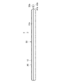
図1及び図2は、本実施形態に係る断熱材1の一例をそれぞれ平面視及び側面視で示す説明図である。図3、図4、図5及び図6は、図1に示すIII−III線、IV−IV線、V−V線及びVI−VI線で切断した断熱材1の断面をそれぞれ示す説明図である。なお、図1〜図6において、同一の数字に異なる小文字のアルファベットを付している部分については、以下の説明において、これらを特に区別する必要がない場合には当該小文字のアルファベットを省略することがある。 FIG.1 and FIG.2 is explanatory drawing which shows an example of the heat insulating material 1 which concerns on this embodiment by a planar view and a side view, respectively. 3, FIG. 4, FIG. 5 and FIG. 6 are explanatory views showing cross sections of the heat insulating material 1 cut along the lines III-III, IV-IV, VV and VI-VI shown in FIG. 1, respectively. is there. In FIGS. 1 to 6, parts having the same numerals with different lower-case alphabets are omitted in the following description unless there is a particular need to distinguish them. There is.
断熱材1は、平均粒径が50nm以下の金属酸化物微粒子を65質量%超、90質量%未満、輻射散乱材を5質量%超、30質量%未満及び補強繊維を2質量%以上、20質量%以下含む板状の乾式加圧成形体10と、繊維製の被覆材20で形成され当該乾式加圧成形体10を収容する外装袋30と、を有している。
The heat insulating material 1 includes metal oxide fine particles having an average particle size of 50 nm or less in excess of 65% by mass and less than 90% by mass, radiation scattering material in excess of 5% by mass and less than 30% by mass, and reinforcing fibers in an amount of 2% by mass or more, 20 It has a plate-shaped dry pressure-molded
乾式加圧成形体10は、金属酸化物微粒子、輻射散乱材及び補強繊維を含む原料粉体を、外装袋30内で乾式加圧成形することにより形成される断熱性成形体である。
The dry pressure molded
金属酸化物微粒子は、平均粒径(より具体的には、当該金属酸化物微粒子の一次粒子の平均粒径)が50nm以下のものであれば特に限られず、任意の1種を単独で又は2種以上を任意に組み合わせて使用することができる。 The metal oxide fine particles are not particularly limited as long as the average particle size (more specifically, the average particle size of the primary particles of the metal oxide fine particles) is 50 nm or less, and any one kind can be used alone or 2 Species or more can be used in any combination.
金属酸化物微粒子の平均粒径は、50nm以下であれば特に限られず、例えば、2nm以上、50nm以下とすることができ、2nm以上、30nm以下とすることもできる。 The average particle diameter of the metal oxide fine particles is not particularly limited as long as it is 50 nm or less. For example, it can be 2 nm or more and 50 nm or less, and can be 2 nm or more and 30 nm or less.
このような金属酸化物微粒子は、その一次粒子が、分子間力等により会合して二次粒子を形成する。乾式加圧成形体10は、この金属酸化物微粒子の二次粒子が集合して形成された多孔構造を有する。すなわち、乾式加圧成形体10は、例えば、金属酸化物微粒子を含むことにより、その内部に、空気分子の平均自由行程よりも小さい(径がナノメートルオーダーの)孔が形成された多孔構造を有する。その結果、乾式加圧成形体10は、低温域から高温域までの幅広い温度範囲で優れた断熱性を発揮する。
In such metal oxide fine particles, the primary particles associate with each other by intermolecular force or the like to form secondary particles. The dry pressure molded
金属酸化物微粒子は、例えば、シリカ微粒子及び/又はアルミナ微粒子であることが好ましく、シリカ微粒子であることが特に好ましい。乾式加圧成形体10がシリカ微粒子を含む場合、当該乾式加圧成形体10は、さらにアルミナ微粒子を含むこととしてもよい。また、乾式加圧成形体10がアルミナ微粒子を含む場合、当該乾式加圧成形体10は、さらにシリカ微粒子を含むこととしてもよい。シリカ微粒子のシリカ(SiO2)含有量及びアルミナ微粒子のアルミナ(Al2O3)含有量は、例えば、95質量%以上であることが好ましい。
The metal oxide fine particles are, for example, preferably silica fine particles and / or alumina fine particles, and particularly preferably silica fine particles. When the dry pressure molded
シリカ微粒子及び/又はアルミナ微粒子としては、気相法で製造されたもの又は湿式法で製造されたものの一方又は両方を使用することができ、気相法で製造されたシリカ微粒子及び/又はアルミナ微粒子を好ましく使用することができる。 As silica fine particles and / or alumina fine particles, one or both of those produced by a gas phase method and those produced by a wet method can be used. Silica fine particles and / or alumina fine particles produced by a gas phase method can be used. Can be preferably used.
すなわち、シリカ微粒子及び/又はアルミナ微粒子としては、気相法で製造された乾式シリカ微粒子(無水シリカ微粒子)及び/又は乾式アルミナ微粒子(無水アルミナ微粒子)を使用することができ、湿式法で製造された湿式シリカ微粒子及び/又は湿式アルミナ微粒子を使用することもでき、中でも乾式シリカ微粒子及び/又は乾式アルミナ微粒子を好ましく使用することができる。 That is, as silica fine particles and / or alumina fine particles, dry silica fine particles (anhydrous silica fine particles) and / or dry alumina fine particles (anhydrous alumina fine particles) produced by a gas phase method can be used, and produced by a wet method. Wet silica fine particles and / or wet alumina fine particles can also be used, and among them, dry silica fine particles and / or dry alumina fine particles can be preferably used.
より具体的に、例えば、気相法で製造されたフュームドシリカ微粒子及び/又はフュームドアルミナ微粒子を好ましく使用することができ、中でも親水性フュームドシリカ微粒子及び/又は親水性フュームドアルミナ微粒子を好ましく使用することができる。 More specifically, for example, fumed silica fine particles and / or fumed alumina fine particles produced by a gas phase method can be preferably used. Among them, fumed silica fine particles and / or hydrophilic fumed alumina fine particles can be used. It can be preferably used.
金属酸化物微粒子のBET法による比表面積は、例えば、50m2/g以上であることが好ましい。より具体的に、この比表面積は、例えば、50〜400m2/gであることが好ましく、100〜400m2/gであることがより好ましい。 The specific surface area of the metal oxide fine particles by the BET method is preferably, for example, 50 m 2 / g or more. More specifically, the specific surface area, for example, is preferably from 50 to 400 m 2 / g, more preferably 100 to 400 m 2 / g.
輻射散乱材は、輻射による伝熱を低減することのできるものであれば特に限られず、任意の1種を単独で又は2種以上を任意に組み合わせて使用することができる。 The radiation scattering material is not particularly limited as long as it can reduce heat transfer by radiation, and any one kind can be used alone or two or more kinds can be arbitrarily combined.
輻射散乱材としては、例えば、炭化珪素、ジルコニア及びチタニアからなる群より選択される1種以上を使用することができ、特に炭化珪素を好ましく使用することができる。炭化珪素は、チタニアやジルコニアに比べて輻射散乱能が優れている。このため、輻射散乱材として炭化珪素を使用する場合には、当該輻射散乱材の含有量を低く抑えることができる。その結果、金属酸化物微粒子の含有量を効果的に高めて、乾式加圧成形体10の特性を特に優れたものとすることができる。
As the radiation scattering material, for example, one or more selected from the group consisting of silicon carbide, zirconia, and titania can be used, and silicon carbide can be particularly preferably used. Silicon carbide is superior in radiation scattering ability compared to titania and zirconia. For this reason, when using silicon carbide as a radiation scattering material, the content of the radiation scattering material can be kept low. As a result, the content of the metal oxide fine particles can be effectively increased, and the characteristics of the dry pressure molded
輻射散乱材の平均粒径は、例えば、1μm以上、50μm以下であることが好ましく、1μm以上、20μm以下であることがより好ましい。輻射散乱材としては、遠赤外線反射性を有するものを好ましく使用することができ、例えば、1μm以上の波長の光に対する比屈折率が1.25以上であるものを特に好ましく使用することができる。 The average particle diameter of the radiation scattering material is, for example, preferably 1 μm or more and 50 μm or less, and more preferably 1 μm or more and 20 μm or less. As the radiation scattering material, those having far-infrared reflectivity can be preferably used, and for example, those having a relative refractive index of 1.25 or more for light having a wavelength of 1 μm or more can be particularly preferably used.
補強繊維は、乾式加圧成形体を補強できるものであれば特に限られず、任意の1種を単独で又は2種以上を任意に組み合わせて使用することができる。補強繊維としては、無機繊維及び/又は有機繊維を使用することができ、無機繊維を好ましく使用することができる。 The reinforcing fiber is not particularly limited as long as it can reinforce the dry pressure-molded body, and any one type can be used alone or two or more types can be used in arbitrary combination. As the reinforcing fibers, inorganic fibers and / or organic fibers can be used, and inorganic fibers can be preferably used.
無機繊維としては、例えば、ガラス繊維、シリカ繊維、アルミナ繊維、シリカアルミナ繊維、ジルコニア繊維、ケイ酸アルカリ土類金属塩繊維、ロックウール及びバサルト繊維からなる群より選択される1種以上を使用することができ、ガラス繊維、シリカアルミナ繊維、シリカ繊維等のシリカ系繊維を好ましく使用することができる。なお、ケイ酸アルカリ土類金属塩繊維は、生体溶解性の無機繊維である。すなわち、無機繊維としては、非生体溶解性無機繊維及び生体溶解性無機繊維の一方又は両方を使用することができる。 As the inorganic fiber, for example, at least one selected from the group consisting of glass fiber, silica fiber, alumina fiber, silica alumina fiber, zirconia fiber, alkaline earth metal silicate fiber, rock wool and basalt fiber is used. Silica-based fibers such as glass fibers, silica-alumina fibers, and silica fibers can be preferably used. The alkaline earth metal silicate fiber is a biosoluble inorganic fiber. That is, as the inorganic fiber, one or both of a non-biosoluble inorganic fiber and a biosoluble inorganic fiber can be used.
有機繊維としては、合成樹脂繊維を使用することができ、例えば、アラミド繊維や、ポリエチレン繊維、ポリプロピレン繊維その他のポリオレフィン繊維を好ましく使用することができる。 As the organic fibers, synthetic resin fibers can be used. For example, aramid fibers, polyethylene fibers, polypropylene fibers and other polyolefin fibers can be preferably used.
補強繊維の繊維長は、例えば、1〜20mmであることが好ましく、1〜10mmであることがより好ましい。補強繊維の平均繊維径は、例えば、2〜20μmであることが好ましく、5〜15μmであることがより好ましい。したがって、補強繊維としては、例えば、繊維長が1〜20mmであって、且つ平均繊維径が2〜20μmであるものを好ましく使用することができる。 The fiber length of the reinforcing fiber is, for example, preferably 1 to 20 mm, and more preferably 1 to 10 mm. For example, the average fiber diameter of the reinforcing fibers is preferably 2 to 20 μm, and more preferably 5 to 15 μm. Therefore, as the reinforcing fiber, for example, a fiber having a fiber length of 1 to 20 mm and an average fiber diameter of 2 to 20 μm can be preferably used.
乾式加圧成形体10における金属酸化物微粒子、輻射散乱材及び補強繊維の含有量は、金属酸化物微粒子65質量%超(例えば、66質量%以上)、90質量%未満(例えば、89質量%以下)、輻射散乱材5質量%超(例えば、6質量%以上)、30質量%未満(例えば、29質量%以下)及び補強繊維2質量%以上、20質量%以下の範囲内であれば特に限られない。 The content of the metal oxide fine particles, the radiation scattering material, and the reinforcing fibers in the dry-pressed compact 10 is more than 65% by mass (for example, 66% by mass or more) and less than 90% by mass (for example, 89% by mass). Or less), more than 5% by mass (for example, 6% by mass or more), less than 30% by mass (for example, 29% by mass or less), and 2% by mass or more and 20% by mass or less of the reinforcing fiber. Not limited.
ここで、本発明において特徴的なことの一つは、乾式加圧成形体10における金属酸化物微粒子の含有量を上記の比較的高い特定の範囲内とし、且つ輻射散乱材及び補強繊維の含有量を上記の特定の範囲内とすることによって、断熱材1の断熱性を十分に維持しつつ、当該断熱材1を変形させた場合においても、当該乾式加圧成形体10の崩壊等の不具合の発生を効果的に抑制できる点にある。
Here, one of the characteristic features of the present invention is that the content of the metal oxide fine particles in the dry pressure-molded
なお、金属酸化物微粒子の含有量が65質量%以下の場合には、乾式加圧成形体10の強度及び柔軟性が不十分となる。輻射散乱材の含有量が5質量%以下の場合には、乾式加圧成形体10の断熱性が不十分となる。補強繊維の含有量が2質量%未満の場合には、乾式加圧成形体10の強度が不十分となる。
In addition, when the content of the metal oxide fine particles is 65% by mass or less, the strength and flexibility of the dry pressure molded
すなわち、本発明の発明者らは、独自に鋭意検討を重ねた結果、断熱材1の断熱性を十分に維持しつつ、当該断熱材1を変形させた場合における不具合の発生を回避するためには、乾式加圧成形体10における金属酸化物微粒子、輻射散乱材及び補強繊維の含有量を、それぞれ上述した特定の範囲内とすることが有効であることを独自に見出し、本発明を完成するに至ったのである。
That is, the inventors of the present invention have made independent studies to avoid the occurrence of problems when the heat insulating material 1 is deformed while sufficiently maintaining the heat insulating property of the heat insulating material 1. Independently finds that it is effective to make the contents of the metal oxide fine particles, the radiation scattering material and the reinforcing fibers in the dry pressure-formed
乾式加圧成形体10は、結合剤を含まないこととしてもよい。この場合、乾式加圧成形体10は、水ガラス接着剤等の無機結合剤や、樹脂等の有機結合剤といった、従来使用されていた結合剤を実質的に含有しない。
The dry pressure molded
結合剤を使用する場合には、例えば、脱脂を行う必要があり、この脱脂によって、製造に要する工程数、所要時間及びエネルギーの増大といった問題に加えて、断熱性成形体の強度が低下するという問題が生じる。また、結合剤の使用によって環境への負荷が増大する。これに対し、乾式加圧成形体10が結合剤を含まないことにより、上述したような結合剤の使用に伴う問題を確実に回避することができる。
When using a binder, for example, it is necessary to degrease, and this degreasing reduces the strength of the heat insulating molded body in addition to problems such as an increase in the number of steps required for production, required time and energy. Problems arise. In addition, the use of a binder increases the environmental load. On the other hand, since the dry pressure molded
乾式加圧成形体10は、例えば、150kg/m3以上の嵩密度を有する断熱性成形体とすることができる。より具体的に、乾式加圧成形体10の嵩密度は、例えば、150〜400kg/m3とすることができ、170〜400kg/m3とすることが好ましく、200〜300kg/m3とすることがより好ましい。
The dry pressure molded
乾式加圧成形体10は、例えば、600℃における熱伝導率が0.08W/(m・K)以下の断熱性成形体とすることができる。乾式加圧成形体10の600℃における熱伝導率は、さらに、例えば、0.05W/(m・K)以下であることが好ましく、0.04W/(m・K)以下であることがより好ましい。
The dry pressure molded
乾式加圧成形体10の600℃における熱伝導率の下限値は特に限られないが、例えば、0.02W/(m・K)である。すなわち、乾式加圧成形体10の600℃における熱伝導率は、例えば、0.02〜0.08W/(m・K)である。
The lower limit value of the thermal conductivity at 600 ° C. of the dry pressure molded
乾式加圧成形体10は、例えば、0.08MPa以上の圧縮強度を有する断熱性成形体とすることができる。乾式加圧成形体10の圧縮強度の上限値は特に限られないが、例えば、1.10MPaである。すなわち、乾式加圧成形体10の圧縮強度は、例えば、0.08〜1.10MPaである。
The dry pressure molded
なお、乾式加圧成形体10の圧縮強度は、その乾式加圧成形面(例えば、当該乾式加圧成形体10の製造時における乾式プレス面)に対して垂直方向に荷重をかけたときの破断強度(MPa)である。
In addition, the compressive strength of the dry pressure-molded
外装袋30を構成する被覆材20は、例えば、無機繊維及び/又は有機繊維製とすることができ、無機繊維製であることが好ましい。被覆材20が無機繊維製であることにより、断熱材1は優れた耐熱性を有することができる。
The covering
無機繊維としては、例えば、ガラス繊維及び/又はセラミックス繊維を好ましく使用することができる。セラミックス繊維としては、例えば、シリカ繊維、アルミナ繊維、シリカアルミナ繊維、アルミノシリケート繊維及びムライト繊維からなる群より選択される1種以上を好ましく使用することができる。有機繊維としては、例えば、アラミド繊維、ポリエステル繊維、ポリエチレンテレフタレート(PET)繊維等の合成樹脂繊維を好ましく使用することができる。 For example, glass fibers and / or ceramic fibers can be preferably used as the inorganic fibers. As the ceramic fiber, for example, one or more selected from the group consisting of silica fiber, alumina fiber, silica alumina fiber, aluminosilicate fiber, and mullite fiber can be preferably used. As the organic fibers, for example, synthetic resin fibers such as aramid fibers, polyester fibers, and polyethylene terephthalate (PET) fibers can be preferably used.
また、被覆材20は、織布又は不織布とすることができ、織布であることが好ましい。織布は、それ自身の発塵性が低い。このため、被覆材20が織布である場合には、断熱材1の発塵を効果的に抑制することができる。また、織布は縫合に適している点でも好ましい。
Moreover, the coating | covering
したがって、被覆材20は、無機繊維及び/又は有機繊維の織布であることが好ましく、特に無機繊維製の織布(例えば、いわゆるガラスクロス)であることが好ましい。また、無機繊維製の織布としては、フッ素樹脂コーティングが施されたものを好ましく使用することができる。
Therefore, the covering
外装袋30は、上述したような被覆材20から形成された袋状体である。外装袋30は、その内部に充填された原料粉末の乾式加圧成形を可能とする通気性を有し、当該乾式加圧成形体に由来する金属酸化物微粒子の漏洩を防止できるものであれば特に限られない。
The
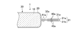
また、図1〜図6に示す例において、外装袋30は、被覆材20の外周端部21を折返して縫合することにより形成された折返し部31(第一折返し部31a、第二折返し部31b及び第三折返し部31c)と、当該乾式加圧成形体10と当該折返し部31との間で当該被覆材20を縫合して形成された中間部32(第一中間部32a、第二中間部32b及び第三中間部32c)と、を有している。
Moreover, in the example shown in FIGS. 1-6, the
折返し部31は、被覆材20の折返された外周端部21を縫合することにより形成される。また、中間部32は、被覆材20のうち、外装袋30に収容された乾式加圧成形体10と、折返し部31と、の間で当該乾式加圧成形体10を囲む部分を縫合することにより形成されている。
The folded portion 31 is formed by stitching the folded outer
図1〜図6に示す例において、折返し部31は、1枚の被覆材20を折り畳むことで重ね合わされる外周端部21を折返して縫合することにより形成されている。すなわち、第一折返し部31a、第二折返し部31b及び第三折返し部31cは、1枚の四角形の被覆材20を折り畳むことで外周端部21が重ね合わされる3辺に形成されている。
In the example shown in FIGS. 1 to 6, the folded portion 31 is formed by folding and stitching the outer
図4に示す第一折返し部31aは、被覆材20の重ね合わされる上外周端部21a及び下外周端部21bのそれぞれを折り返し、且つ当該上外周端部21a及び下外周端部21bのそれぞれを縫合することにより形成されている。
The first folded
図5に示す第二折返し部31bは、被覆材20の重ね合わされる上外周端部21a及び下外周端部21bのそれぞれを折り返し、且つ当該上外周端部21a及び下外周端部21bをまとめて縫合することにより形成されている。
The second folded
図6に示す第三折返し部31cは、被覆材20の重ね合わされる上外周端部21a及び下外周端部21bをまとめて折り返し、且つ当該上外周端部21a及び下外周端部21bをまとめて縫合することにより形成されている。
The third folded
なお、上外周端部21a及び下外周端部21bをまとめて折り返す場合、2回以上折り返すことが好ましい。図6に示す例において、上外周端部21a及び下外周端部21bはまとめて2回折り返されている。
In addition, when the upper outer
また、図1〜図6に示す例において、第一中間部32a、第二中間部32b及び第三中間部32cは、乾式加圧成形体10と、第一折返し部31a、第二折返し部31b及び第三折返し部31cと、の間にそれぞれ形成されている。
Moreover, in the example shown in FIGS. 1-6, the 1st
折返し部31及び中間部32を有する外装袋30は、当該折返し部31及び中間部32に対応して、乾式加圧成形体10を囲む二重の縫目40,41を有している。
The
すなわち、図1〜図6に示すように、外装袋30は、折返し部31及び中間部32にそれぞれ対応する外側縫目40及び内側縫目41を有している。具体的に、外装袋30は、第一折返し部31a、第二折返し部31b及び第三折返し部31cにそれぞれ形成された第一外側縫目40a、第二外側縫目40b及び第三外側縫目40cと、第一中間部32a、第二中間部32b及び第三中間部32cにそれぞれ形成された第一内側縫目41a、第二内側縫目41b及び第三内側縫目41cとを有している。なお、図4に示す第一折返し部31aにおいては、上外周端部21a及び下外周端部21bのそれぞれに第一外側縫目40bが形成されている。
That is, as shown in FIGS. 1 to 6, the
被覆材20の縫合に使用される縫合糸は、折返し部31及び中間部32を形成できるものであれば特に限られず、無機繊維糸及び/又は有機繊維糸を使用することができ、特に無機繊維糸を好ましく使用することができる。
The suture used for stitching the covering
無機繊維糸としては、例えば、ガラス繊維糸、セラミックス繊維糸及び金属繊維糸からなる群より選択される1種以上を好ましく使用することができる。セラミックス繊維糸としては、例えば、シリカ繊維糸、アルミナ繊維糸、シリカアルミナ繊維糸、アルミノシリケート繊維糸、ムライト繊維糸及び炭素繊維糸からなる群より選択される1種以上を好ましく使用することができる。有機繊維糸としては、例えば、ナイロン糸、レーヨン糸、ポリエステル糸、綿糸及び絹糸からなる群より選択される1種以上を好ましく使用することができる。金属繊維糸としては、例えば、ステンレス糸(より具体的には、例えば、ナスロン(登録商標))、アルミニウム糸、金糸、銀糸及び銅糸からなる群より選択される1種以上を好ましく使用することができる。 As the inorganic fiber yarn, for example, one or more selected from the group consisting of glass fiber yarn, ceramic fiber yarn and metal fiber yarn can be preferably used. As the ceramic fiber yarn, for example, one or more selected from the group consisting of silica fiber yarn, alumina fiber yarn, silica alumina fiber yarn, aluminosilicate fiber yarn, mullite fiber yarn and carbon fiber yarn can be preferably used. . As the organic fiber yarn, for example, one or more selected from the group consisting of nylon yarn, rayon yarn, polyester yarn, cotton yarn and silk yarn can be preferably used. As the metal fiber yarn, for example, at least one selected from the group consisting of stainless steel yarn (more specifically, for example, NASRON (registered trademark)), aluminum yarn, gold yarn, silver yarn and copper yarn is preferably used. Can do.
なお、外装袋30は、1枚の被覆材20から形成されるものに限られず、2枚以上の被覆材20から形成されてもよい。すなわち、例えば、外装袋30が2枚の被覆材20から形成される場合、折返し部31は、当該2枚の被覆材20を重ね合わせることで重ね合わされる外周端部21を折返して縫合することにより形成される。より具体的に、折返し部31は、例えば、2枚の四角形の被覆材20を重ね合わせることで外周端部21が重ね合わされる4辺に形成される。ただし、外装袋30の形状は四角形に限られず、例えば、他の多角形であってもよい。
The
また、外装袋30の3辺又は4辺のそれぞれにおいては、図4、図5及び図6に示す折返し方法のいずれを採用してもよい。すなわち、例えば、第二折返し部31b及び第三折返し部31cにおいて、図5及び図6に示す折返し方法を任意に組み合わせて採用してもよい。また、折返し部31における外周端部21の折返し方法は、図4〜図6に示す例に限られない。
Moreover, in each of 3 sides or 4 sides of the
また、図1に示す例において、中間部32の内側縫目41は、外装袋30の一方端から他方端まで形成されているが、乾式加圧成形体10を囲むように形成されれば、これに限られず、例えば、その少なくとも一部が外装袋30の端部まで到達しないこととしてもよい。
In the example shown in FIG. 1, the inner seam 41 of the intermediate portion 32 is formed from one end to the other end of the
外装袋30に折返し部31及び中間部32を形成することによって、被覆材20の外周端部21に繊維のほつれが生じることを効果的に回避することができるとともに、乾式加圧成形体10に由来する粉塵が当該外装袋30から外部に漏洩することを効果的に防止することができる。
By forming the folded portion 31 and the intermediate portion 32 in the
このような乾式加圧成形体10及び外装袋30を有する断熱材1の形状及びサイズは、当該断熱材1を施工すべき表面(例えば、湾曲した表面)の形状等、その施工条件に応じて適宜決定することができる。すなわち、断熱材1は、例えば、図1〜図6に示すように、乾式加圧成形体10の形状に対応した板状体(いわゆるパネル型製品)とすることができる。
The shape and size of the heat insulating material 1 having such a dry press-molded
断熱材1の厚さは、特に限られないが、例えば、30mm以下とすることができる。より具体的に、断熱材1の厚さは、例えば、2mm以上、30mm以下とすることができ、5mm以上、25mm以下とすることが好ましい。断熱材1の厚さがこれらの範囲であることにより、当該断熱材1を変形させた場合における不具合の発生を特に効果的に抑制することができる。 Although the thickness of the heat insulating material 1 is not specifically limited, For example, it can be 30 mm or less. More specifically, the thickness of the heat insulating material 1 can be, for example, 2 mm or more and 30 mm or less, and is preferably 5 mm or more and 25 mm or less. When the thickness of the heat insulating material 1 is within these ranges, the occurrence of problems when the heat insulating material 1 is deformed can be particularly effectively suppressed.
本実施形態に係る断熱材1の製造方法(以下、「本方法」という。)は、乾式加圧成形体10と、当該乾式加圧成形体10を収容する外装袋30と、を有する断熱材1を製造する方法であって、平均粒径が50nm以下の金属酸化物微粒子を65質量%超、90質量%未満、輻射散乱材を5質量%超、30質量%未満及び補強繊維を2質量%以上、20質量%以下含む原料粉体を、繊維製の被覆材20で形成された当該外装袋30に充填し、当該外装袋30内の当該原料粉体を乾式加圧成形して当該乾式加圧成形体10を形成することを含む。
A method for manufacturing the heat insulating material 1 according to the present embodiment (hereinafter referred to as “the present method”) includes a dry pressure molded
すなわち、本方法においては、まず、金属酸化物微粒子、輻射散乱材及び補強繊維を上述の特定の配合比率で乾式にて混合することにより、原料粉体を調製する。具体的に、例えば、金属酸化物微粒子の乾燥粉体と、輻射散乱材の乾燥粉体と、補強繊維の乾燥粉体とを、所定の混合装置を使用して乾式混合する。 That is, in this method, first, the raw material powder is prepared by mixing the metal oxide fine particles, the radiation scattering material, and the reinforcing fibers in a dry manner at the above-described specific blending ratio. Specifically, for example, dry powder of metal oxide fine particles, dry powder of radiation scattering material, and dry powder of reinforcing fibers are dry-mixed using a predetermined mixing device.
一方、被覆材20の外周端部21を縫合することにより、一部が開口した外装袋30を形成する。すなわち、図1〜図6に示す例においては、第一折返し部31aが形成される1辺が開口し、他の3辺が封止された外装袋30を形成する。
On the other hand, the outer
次いで、この外装袋30の開口部分から、当該外装袋30内に上述の原料粉体を入れる。そして、乾式のプレス成形により、外装袋30内に充填された原料粉体を圧縮成形することで、当該外装袋30内において所定の形状及びサイズを有する板状の乾式加圧成形体10を形成する。その後、外装袋30の開口部分を封止して、断熱材1を得る。
Next, the raw material powder is put into the
なお、乾式加圧成形を行う温度は、特に制限はないが、例えば、5℃以上、60℃以下の温度で行うことができる。また、原料粉体の混合及び成形を乾式で行うことにより、湿式の場合に比べて、当該原料粉体の管理が容易となり、また、断熱材1の製造に要する時間を効果的に短縮することができる。 In addition, although the temperature which performs dry-type pressure molding does not have a restriction | limiting in particular, For example, it can carry out at the temperature of 5 degreeC or more and 60 degrees C or less. Moreover, by mixing and forming the raw material powders in a dry manner, the raw material powders can be easily managed and the time required for manufacturing the heat insulating material 1 can be effectively shortened as compared with the wet case. Can do.
また、本実施形態に係る本方法は、被覆材20の外周端部21を折返して縫合することにより外装袋30の折返し部31を形成するとともに、当該被覆材20の当該乾式加圧成形体10と当該折返し部31との間の部分を縫合することをさらに含む。すなわち、本方法においては、乾式加圧成形体10を囲む二重の縫目40,41を形成するように、被覆材20の折返された外周端部21と、当該被覆材20の当該乾式加圧成形体10を囲む部分と、を縫合する。
In addition, the present method according to the present embodiment forms the folded portion 31 of the
具体的に、図1〜図6に示す例においては、外装袋30に原料粉体を充填する前に、封止された第二折返し部31b及び第三折返し部31cと、開口した第一折返し部31aと、を有する外装袋30を形成する。すなわち、例えば、まず1枚の被覆材20を折り畳み、次いで、乾式加圧成形体10が形成されるべき範囲の外周の一部を縫合して第二中間部32b及び第三中間部32cを形成する。さらに、第二中間部32b及び第三中間部32cに対応する被覆材20の外周端部21を折返すとともに縫合して、第二折返し部31b及び第三折返し部31cを形成する。また、残りの外周端部21において、図4に示すように上外周端部21a及び下外周端部21bをそれぞれ縫合し、外装袋30の開口部として第一折返し部31aを形成する。
Specifically, in the example shown in FIGS. 1 to 6, before the
そして、外装袋30の開口する第一折返し部31aから、当該外装袋30に原料粉体を充填するとともに、当該外装袋30内の原料粉体に乾式加圧成形を施して、乾式加圧成形体10を形成する。その後、乾式加圧成形体10と第一折返し部31aとの間を縫合して第一中間部32aを形成することにより、外装袋30の開口部を封止する。この結果、外装袋30内に封入された乾式加圧成形体10を有する断熱材1が得られる。
Then, the
本発明によれば、変形させた場合における不具合の発生が効果的に抑制された断熱材1及びその製造方法を提供することができる。すなわち、上述した断熱材1は、優れた断熱性と、変形させて使用した場合(例えば、湾曲した表面に沿った施工した場合)であっても不具合(例えば、乾式加圧成形体10の崩壊や、これに伴う発塵)を生じない優れた強度及び柔軟性と、を兼ね備えている。 ADVANTAGE OF THE INVENTION According to this invention, the heat insulating material 1 with which generation | occurrence | production of the malfunction in the case of making it deform | transformed was suppressed effectively, and its manufacturing method can be provided. That is, the above-described heat insulating material 1 has excellent heat insulating properties and a defect even when it is used after being deformed (for example, when it is applied along a curved surface) (for example, collapse of the dry pressure molded body 10). In addition, it has excellent strength and flexibility that does not cause dust generation associated therewith.
具体的に、例えば、断熱材1の乾式加圧成形体10は、上述した特定の配合比率で金属酸化物微粒子、輻射散乱材及び補強繊維を含むことにより、優れた断熱性を維持しつつ、変形した場合においても、崩壊等の不具合を生じにくい。
Specifically, for example, the dry pressure molded
このため、断熱材1は、例えば、いわゆるキルティング製品とする必要がない。すなわち、断熱材1においては、乾式加圧成形体10及び外装袋30を貫通する縫合(キルティング加工)を行う必要がない。また、断熱材1は、いわゆるスラット製品とする必要がない。すなわち、断熱材1においては、乾式加圧成形体10を離隔して配置される複数の部分に分割する必要がない。
For this reason, the heat insulating material 1 does not need to be what is called a quilting product, for example. That is, in the heat insulating material 1, it is not necessary to perform stitching (quilting processing) that penetrates the dry pressure molded
また、例えば、外装袋30が折返し部31及び中間部32を有することにより、被覆材20の外周端部21における繊維のほつれを効果的に回避できるとともに、変形した乾式加圧成形体10に由来する粉塵が外装袋30外に漏洩することを効果的に防止することができる。
Further, for example, the
したがって、断熱材1は、一般工業炉や燃料電池の改質器等、様々な構造物の湾曲した表面や凹凸の形成された表面において、不具合の発生を効果的に回避しつつ優れた断熱性を発揮することができる。 Therefore, the heat insulating material 1 has excellent heat insulating properties while effectively avoiding the occurrence of defects on curved surfaces and uneven surfaces of various structures such as general industrial furnaces and fuel cell reformers. Can be demonstrated.
次に、本実施形態に係る具体的な実施例について説明する。 Next, specific examples according to the present embodiment will be described.
[断熱材の製造]
金属酸化物微粒子として、一次粒子の平均粒径が約13nmの無水シリカ微粒子(親水性フュームドシリカ微粒子)を使用した。輻射散乱材として、平均粒径1.8μmの炭化珪素(SiC)を使用した。補強繊維として、平均繊維径11μm、平均繊維長6mmのEガラス繊維を使用した。被覆材20として、サイズが885mm×1640mm、厚さ0.27mm、坪量が314g/m2のEガラス繊維製の織布(ガラスクロス)を使用した。縫合糸として、平均径が約1mmのガラス繊維糸を使用した。
[Manufacture of insulation materials]
As metal oxide fine particles, anhydrous silica fine particles (hydrophilic fumed silica fine particles) having an average primary particle size of about 13 nm were used. Silicon carbide (SiC) having an average particle size of 1.8 μm was used as the radiation scattering material. As the reinforcing fiber, E glass fiber having an average fiber diameter of 11 μm and an average fiber length of 6 mm was used. As the covering
これらの材料を使用して、断熱材1を製造した。すなわち、上述したシリカ微粒子、炭化珪素及びガラス繊維を混合装置に投入し、乾式混合することにより、当該シリカ微粒子、炭化珪素及びガラス繊維を所定の比率で含み、結合剤を含まない原料粉体を得た。 The heat insulating material 1 was manufactured using these materials. That is, by introducing the silica fine particles, silicon carbide and glass fibers described above into a mixing apparatus and dry-mixing, a raw material powder containing the silica fine particles, silicon carbide and glass fibers in a predetermined ratio and not containing a binder is obtained. Obtained.
一方、ガラスクロスから、開口部を有する外装袋30を形成した。すなわち、1枚のガラスクロスを折り畳むことにより重ね合わされる3辺の外周端部21の全てを折返し、これらのうち2辺においては、折返された外周端部21を縫合糸で縫合して折返し部31及び中間部32を形成し、他の1辺においては、原料粉体を入れるための開口部を形成するように上外周端部21a及び下外周端部21bのそれぞれを縫合糸で縫合した(図4参照)。
On the other hand, the
そして、この外装袋30内に適量の原料粉体を充填した。次いで、外装袋30内の原料粉体に乾式プレスを施すことにより、当該外装袋30内に収容された板状の乾式加圧成形体10(サイズは、約800mm×約850mm、厚さ約10mm)を形成した。なお、乾式プレス成形においては、乾式加圧成形体10の嵩密度が250kg/m3となるようにプレス圧を調節した。
Then, an appropriate amount of raw material powder was filled in the
その後、開口部を構成する1辺において、乾式加圧成形体10と折返し部31との間を縫合して中間部32を形成することにより、外装袋30を封止した。こうして、シリカ微粒子、炭化珪素及びガラス繊維を含む板状の乾式加圧成形体10と、ガラス繊維糸で縫合された折返し部31及び中間部32を有するガラス繊維製の外装袋30と、を有する厚さ10mmの断熱材1を得た。
Thereafter, the
なお、断熱材1としては、乾式加圧成形体10におけるシリカ微粒子及び炭化珪素の含有量が異なる(シリカ微粒子の含有量が65〜95質量%、炭化珪素の含有量が0〜30質量%、ガラス繊維の含有量が5質量%)7種類を製造した。
In addition, as the heat insulating material 1, the content of silica fine particles and silicon carbide in the dry pressure-molded
[熱伝導率の評価]
乾式加圧成形体10の600℃における熱伝導率を周期加熱法にて測定した。すなわち、上述のように外装袋30内で乾式加圧成形体10を形成した後、当該外装袋30から当該乾式加圧成形体10を取り出し、当該乾式加圧成形体10の熱伝導率を測定した。
[Evaluation of thermal conductivity]
The thermal conductivity at 600 ° C. of the dry pressure molded
具体的に、乾式加圧成形体10から切り出した所定サイズの試験体内に温度波を伝播させ、その伝播時間から熱拡散率を測定した。そして、この熱拡散率と、別途測定した比熱及び密度と、から熱伝導率を算出した。なお、温度波としては、温度振幅が約4℃、周期が約1時間である温度の波を使用した。また、試験体内の2つの地点を温度波が通過するのに要する時間を伝播時間とした。
Specifically, a temperature wave was propagated in a test body of a predetermined size cut out from the dry pressure molded
[圧縮強度の評価]
乾式加圧成形体10の圧縮強度を、万能試験装置(テンシロン RTC−1150A、株式会社オリエンテック)を用いて測定した。すなわち、まず、上述の熱伝導率の測定と同様に、乾式プレス成形後に乾式加圧成形体10を外装袋30から取り出し、当該乾式加圧成形体10から寸法30mm×15mm×厚さ25mmの試験体を切り出した。次いで、この試験体のプレス面(30mm×15mm)に対して垂直方向に(すなわち、当該試験体の当該プレス面に垂直な表面(15mm×25mm)に対して)荷重を負荷した。
[Evaluation of compressive strength]
The compressive strength of the dry press-molded
そして、試験体が破断したときの荷重(最大荷重)(N)を、荷重を負荷した表面(プレス面に垂直な表面)の面積(m2)で除した値を圧縮強度(MPa)として評価した。 Then, a value obtained by dividing the load (maximum load) (N) when the specimen is broken by the area (m 2 ) of the surface (surface perpendicular to the press surface) on which the load is applied is evaluated as the compressive strength (MPa). did.
[巻き付け施工試験]
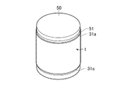
湾曲した表面への施工における断熱材1の適性を評価するため、図7に示すような巻き付け施工試験を行った。すなわち、まず、断熱材1を施工する構造物として、直径が500mmの鉄製の円筒体50を準備した。
[Winding work test]
In order to evaluate the suitability of the heat insulating material 1 in construction on a curved surface, a winding construction test as shown in FIG. 7 was performed. That is, first, an
次いで、図7に示すように、断熱材1を、その長手方向に湾曲させながら、円筒体50の外周面51(円筒側面)に巻き付けた。巻き付けられた断熱材1は、不図示のポリプロピレン製バンドで締め付けて固定した。
Next, as shown in FIG. 7, the heat insulating material 1 was wound around the outer peripheral surface 51 (cylindrical side surface) of the
そして、円筒体50の外周面51に対する断熱材1の巻き付け性(フィッティング性)を目視で評価した。
And the winding property (fitting property) of the heat insulating material 1 with respect to the outer
[評価結果]
図8には、7種類の断熱材1のそれぞれについて、乾式加圧成形体10におけるシリカ微粒子、炭化珪素及びガラス繊維の含有量(質量%)と、当該乾式加圧成形体10の熱伝導率(W/(m・K))及び圧縮強度(MPa)と、当該断熱材1の巻き付け性及び総合評価と、を示す。
[Evaluation results]
FIG. 8 shows the contents (mass%) of silica fine particles, silicon carbide and glass fibers in the dry pressure molded
なお、図8の「熱伝導率」欄、「圧縮強度」欄及び「巻き付け性」欄において、二重丸印(◎)は特性が極めて優れていたことを示し、丸印(○)は特性が優れていたことを示し、三角印(△)は特性が実用上は十分であったことを示し、バツ印(×)は特性が不十分であったことを示している。 In the “thermal conductivity” column, “compressive strength” column, and “winding property” column of FIG. 8, double circles ()) indicate that the characteristics are extremely excellent, and circles (◯) indicate the characteristics. The triangle mark (Δ) indicates that the characteristics were sufficient for practical use, and the cross mark (×) indicates that the characteristics were insufficient.
また、「総合評価」欄において、丸印(○)は断熱材1の特性が総合的に優れていたことを示し、三角印(△)は断熱材1の特性が総合的に実用上は十分であったことを示し、バツ印(×)は断熱材1の特性が総合的に不十分であったことを示している。 In the “Comprehensive Evaluation” column, a circle (◯) indicates that the characteristics of the heat insulating material 1 are comprehensively excellent, and a triangle (Δ) indicates that the characteristics of the heat insulating material 1 are comprehensively sufficient for practical use. The cross mark (x) indicates that the properties of the heat insulating material 1 were generally insufficient.
図8に示すように、乾式加圧成形体10におけるシリカ微粒子の含有量が65質量%の場合には、圧縮強度が不十分で、且つ断熱材1と円筒体50との間に隙間が形成される等、巻き付け性も不十分であり、その結果、総合的に特性が不十分と評価された。
As shown in FIG. 8, when the content of silica fine particles in the dry pressure molded
また、乾式加圧成形体10における炭化珪素の含有量が0質量%及び5質量%の場合には、当該乾式加圧成形体10の熱伝導率が大きく断熱性が不十分であり、その結果、総合的に特性が不十分と評価された。
Moreover, when the content of silicon carbide in the dry pressure molded
これらに対し、乾式加圧成形体10におけるシリカ微粒子の含有量が70〜85質量%及び炭化珪素の含有量が10〜25質量%の場合には、当該乾式加圧成形体10の熱伝導率が小さく断熱性は十分であり、且つ圧縮強度が大きく強度も十分である上に、断熱材1と円筒体50との間にはほとんど隙間が形成されず、巻き付け性も良好であった。その結果、この場合の断熱材1の特性は総合的に実用上、十分なものと評価された。
On the other hand, when the content of silica fine particles in the dry pressure molded
このように、乾式加圧成形体10におけるシリカ微粒子、炭化珪素及び補強繊維の含有量を特定の範囲とすることによって、断熱性、強度及び柔軟性の全てを十分に兼ね備えた断熱材1を実現できることが確認された。
In this way, by making the content of the silica fine particles, silicon carbide and reinforcing fibers in the dry pressure-molded
[断熱材の製造]
上述の実施例1と同様に、シリカ微粒子75質量%、炭化珪素20質量%及びガラス繊維5質量%を含み結合剤を含まない板状の乾式加圧成形体10からなる基材と、ガラス繊維糸で縫合された折返し部31及び中間部32を有するガラス繊維製の外装袋30と、を有し、厚さが10mm、15mm又は20mmの3種類の断熱材1を製造した。
[Manufacture of insulation materials]
In the same manner as in Example 1 above, a substrate composed of a plate-shaped dry pressure molded
[巻き付け施工試験]
上述の実施例1と同様に、直径が400mm、500mm又は600mmの3種類の鉄製の円筒体50のそれぞれに、断熱材1を巻き付けた。そして、上述の実施例1と同様に、円筒体50の外周面51に対する断熱材1の巻き付け性(フィッティング性)を目視で評価した。
[Winding work test]
In the same manner as in Example 1 described above, the heat insulating material 1 was wound around each of three types of
さらに、断熱材1を円筒体50から取り外し、その外装袋30をカッターで切断して基材(乾式加圧成形体10)を露出させ、当該基材の状態を目視で観察した。
Furthermore, the heat insulating material 1 was removed from the
また、比較の対象として、シリカ微粒子60〜65質量%、チタニア30〜35質量%及びアルミナ繊維2〜3質量%を含む板状の成形体からなる基材と、当該成形体を収容するガラス繊維製の外装袋と、を有し、厚さが10mm、15mm又は20mmの3種類の市販の断熱材(マイクロサームパネル、日本マイクロサーム株式会社製)についても、同様の巻き付け施工試験を行った。なお、この市販の断熱材の外装袋の外周端部は折返されることなく縫合され、当該外周端部には成形体を囲むように一重の縫目のみが形成されていた。 Further, as a comparison object, a base material composed of a plate-shaped molded body containing 60 to 65 mass% of silica fine particles, 30 to 35 mass% of titania and 2 to 3 mass% of alumina fibers, and a glass fiber containing the molded body. A similar wrapping test was performed on three types of commercially available heat insulating materials (Microtherm Panel, manufactured by Nippon Microtherm Co., Ltd.) having a thickness of 10 mm, 15 mm, or 20 mm. It should be noted that the outer peripheral end portion of this commercially available heat-insulating outer packaging bag was stitched without being folded back, and only a single stitch was formed on the outer peripheral end portion so as to surround the molded body.
[評価結果]
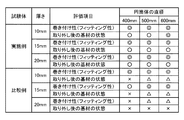
図9には、3種類の断熱材1(図9に示す「実施例」)及び3種類の市販断熱材(図9に示す「比較例」)のそれぞれについて、3種類の円筒体50を使用した巻き付け施工試験において、当該断熱材の巻き付け性と、取り外し後の基材の状態と、を評価した結果を示す。
[Evaluation results]
In FIG. 9, three types of
なお、図9の「巻き付け性(フィッティング性)」欄において、二重丸印(◎)は、断熱材が円筒体50の外周面51に沿って隙間なく配置され、巻き付け性が極めて優れていたことを示し、丸印(○)は、断熱材と円筒体50の外周面51との間に僅かな隙間が形成されていたが巻き付け性は優れていたことを示し、三角印(△)は、断熱材と円筒体50の外周面51との間に隙間は形成されていたが巻き付け性は実用上は十分であったことを示し、バツ印(×)は、断熱材と円筒体50の外周面51との間に大きな隙間が形成されて巻き付け性は不十分であったことを示している。
In the “winding property (fitting property)” column of FIG. 9, the double circles (◎) indicate that the heat insulating material is arranged without a gap along the outer
また、「取り外し後の基材の状態」欄において、二重丸印(◎)は、基材に亀裂等の不具合は全く生じておらず、巻き付け施工後の状態は極めて良好であったことを示し、丸印(○)は、基材に僅かな亀裂は認められたものの、巻き付け施工後の状態は良好であったことを示し、三角印(△)は、基材の一部が崩壊しており、巻き付け施工後の状態は不良であったことを示し、バツ印(×)は、基材の大部分が崩壊しており、巻き付け施工後の状態は極めて不良であったことを示している。 In addition, in the “Base material state after removal” column, double circles (◎) indicate that the base material had no defects such as cracks, and the state after winding was extremely good. The circle mark (◯) indicates that although the substrate was slightly cracked, the state after winding was good, and the triangle mark (Δ) indicates that a part of the substrate collapsed. It shows that the state after the winding work was bad, and the cross mark (×) shows that the majority of the base material has collapsed and the state after the winding work was extremely bad. Yes.
図9に示すように、比較例に係る3種類の市販の断熱材は、いずれも巻き付け施工後の基材の一部又は大部分が崩壊していた。このような基材の崩壊は、断熱性の著しい低下や発塵等の不具合をもたらすものである。 As shown in FIG. 9, as for all three types of commercially available heat insulating materials which concern on a comparative example, a part or most part of the base material after winding construction has collapsed. Such a collapse of the base material causes problems such as a significant decrease in heat insulation and dust generation.
これに対し、実施例に係る3種類の断熱材1は、いずれも巻き付け性及び巻き付け施工後の基材の状態が良好であった。すなわち、これらの断熱材1は、構造物の表面に沿って湾曲して施工された場合であっても、断熱性の低下や発塵等の不具合を生じることなく、優れた断熱性を発揮できることが確認された。 On the other hand, as for all three types of heat insulating materials 1 which concern on an Example, the state of the base material after winding property and winding construction was favorable. That is, these heat insulating materials 1 can exhibit excellent heat insulating properties without causing problems such as a decrease in heat insulating properties and generation of dust even when they are constructed while being curved along the surface of the structure. Was confirmed.
1 断熱材、10 乾式加圧成形体、20 被覆材、21 外周端部、21a 上外周端部、21b 下外周端部、30 外装袋、31 折返し部、31a 第一折返し部、31b 第二折返し部、31c 第三折返し部、32 中間部、32a 第一中間部、32b 第二中間部、32c 第三中間部、40 外側縫目、40a 第一外側縫目、40b 第二外側縫目、40c 第三外側縫目、41 内側縫目、41a 第一内側縫目、41b 第二内側縫目、41c 第三内側縫目、50 円筒体 51 外周面。
DESCRIPTION OF SYMBOLS 1 Heat insulating material, 10 Dry press-molded body, 20 Coating | covering material, 21 Outer peripheral edge part, 21a Upper outer peripheral edge part, 21b Lower outer peripheral edge part, 30 Exterior bag, 31 Folding part, 31a First folding part, 31b Second folding Part, 31c third folded part, 32 intermediate part, 32a first intermediate part, 32b second intermediate part, 32c third intermediate part, 40 outer seam, 40a first outer seam, 40b second outer seam, 40c Third outer seam, 41 inner seam, 41a first inner seam, 41b second inner seam, 41c third inner seam, 50
Claims (11)
繊維製の被覆材で形成され前記乾式加圧成形体を収容する外装袋と、
を有する
ことを特徴とする断熱材。 A plate containing metal oxide fine particles having an average particle size of 50 nm or less in excess of 65% by mass and less than 90% by mass, radiation scattering material in excess of 5% by mass and less than 30% by mass, and reinforcing fibers in an amount of 2% by mass to 20% by mass A dry pressure molded body,
An outer bag formed of a fiber covering material and containing the dry pressure-molded body;
A heat insulating material characterized by comprising:
前記被覆材の外周端部を折返して縫合することにより形成された折返し部と、
前記被覆材の前記乾式加圧成形体と前記折返し部との間の部分を縫合して形成された中間部と、
を有する
ことを特徴とする請求項1に記載された断熱材。 The outer bag is
A folded portion formed by folding and sewing the outer peripheral end of the covering material;
An intermediate portion formed by stitching a portion between the dry pressure-molded body of the covering material and the folded portion;
It has these. The heat insulating material described in Claim 1 characterized by the above-mentioned.
ことを特徴とする請求項2に記載された断熱材。 The heat insulating material according to claim 2, wherein the covering material is stitched with an inorganic fiber thread.
ことを特徴とする請求項3に記載された断熱材。 The said inorganic fiber yarn is 1 or more types selected from the group which consists of a glass fiber yarn, a ceramic fiber yarn, and a metal fiber yarn. The heat insulating material described in Claim 3 characterized by the above-mentioned.
ことを特徴とする請求項1乃至4のいずれかに記載された断熱材。 The said coating | covering material is a product made from an inorganic fiber. The heat insulating material described in any one of Claims 1 thru | or 4 characterized by the above-mentioned.
ことを特徴とする請求項1乃至5のいずれかに記載された断熱材。 The heat insulating material according to any one of claims 1 to 5, wherein the metal oxide fine particles are silica fine particles and / or alumina fine particles.
ことを特徴とする請求項1乃至6のいずれかに記載された断熱材。 The heat-radiating material according to any one of claims 1 to 6, wherein the radiation scattering material is silicon carbide.
ことを特徴とする請求項1乃至7のいずれかに記載された断熱材。 The heat insulating material according to any one of claims 1 to 7, wherein the heat insulating material does not contain a binder.
ことを特徴とする請求項1乃至8のいずれかに記載された断熱材。 The heat insulating material according to any one of claims 1 to 8, wherein a thickness is 30 mm or less.
平均粒径が50nm以下の金属酸化物微粒子を65質量%超、90質量%未満、輻射散乱材を5質量%超、30質量%未満及び補強繊維を2質量%以上、20質量%以下含む原料粉体を、繊維製の被覆材で形成された前記外装袋に充填し、前記外装袋内の前記原料粉体を乾式加圧成形して前記乾式加圧成形体を形成することを含む
ことを特徴とする断熱材の製造方法。 A method for producing a heat insulating material having a dry pressure molded body and an outer bag containing the dry pressure molded body,
Raw material containing metal oxide fine particles having an average particle size of 50 nm or less in excess of 65% by mass and less than 90% by mass, radiation scattering material in excess of 5% by mass and less than 30% by mass, and reinforcing fibers in an amount of 2% by mass to 20% by mass Filling the outer bag formed with a fiber covering material, and dry pressing the raw material powder in the outer bag to form the dry pressure molded body. A method for producing a heat insulating material.
ことを特徴とする請求項10に記載された断熱材の製造方法。 The outer circumferential end of the covering material is folded and stitched to form the folded portion of the outer bag, and the portion of the coating material between the dry pressure-molded body and the folded portion is further stitched The manufacturing method of the heat insulating material described in Claim 10 characterized by the above-mentioned.
Priority Applications (2)
| Application Number | Priority Date | Filing Date | Title |
|---|---|---|---|
| JP2011006475A JP5438695B2 (en) | 2011-01-14 | 2011-01-14 | Insulating material and manufacturing method thereof |
| PCT/JP2011/079567 WO2012096110A1 (en) | 2011-01-14 | 2011-12-20 | Heat insulator and process for producing same |
Applications Claiming Priority (1)
| Application Number | Priority Date | Filing Date | Title |
|---|---|---|---|
| JP2011006475A JP5438695B2 (en) | 2011-01-14 | 2011-01-14 | Insulating material and manufacturing method thereof |
Publications (3)
| Publication Number | Publication Date |
|---|---|
| JP2012149658A true JP2012149658A (en) | 2012-08-09 |
| JP2012149658A5 JP2012149658A5 (en) | 2013-02-07 |
| JP5438695B2 JP5438695B2 (en) | 2014-03-12 |
Family
ID=46507022
Family Applications (1)
| Application Number | Title | Priority Date | Filing Date |
|---|---|---|---|
| JP2011006475A Active JP5438695B2 (en) | 2011-01-14 | 2011-01-14 | Insulating material and manufacturing method thereof |
Country Status (2)
| Country | Link |
|---|---|
| JP (1) | JP5438695B2 (en) |
| WO (1) | WO2012096110A1 (en) |
Cited By (5)
| Publication number | Priority date | Publication date | Assignee | Title |
|---|---|---|---|---|
| WO2014091665A1 (en) * | 2012-12-11 | 2014-06-19 | ニチアス株式会社 | Insulation material and method of manufacturing same |
| JP2015143532A (en) * | 2014-01-31 | 2015-08-06 | ニチアス株式会社 | Heat insulator and method of manufacturing the same |
| JP5863917B1 (en) * | 2014-09-22 | 2016-02-17 | ニチアス株式会社 | Refractory structure and method of use |
| CN109973760A (en) * | 2018-05-11 | 2019-07-05 | 上海邦季新材料有限公司 | The preparation method of vacuum insulation panel glass fiber core material |
| JP2022066243A (en) * | 2019-08-27 | 2022-04-28 | イビデン株式会社 | Heat insulation sheet for battery pack and battery pack |
Citations (4)
| Publication number | Priority date | Publication date | Assignee | Title |
|---|---|---|---|---|
| JPS5140088B1 (en) * | 1970-06-10 | 1976-11-01 | ||
| JPH09217890A (en) * | 1996-02-13 | 1997-08-19 | Micropore Internatl Ltd | Flexible thermal insulation panel and manufacture thereof |
| US20040123905A1 (en) * | 2002-12-30 | 2004-07-01 | Petschek Eric Bradley | Thermal cover for backflow prevention assemblies |
| JP2008164078A (en) * | 2006-12-28 | 2008-07-17 | Nichias Corp | Heat insulating material for reformer |
-
2011
- 2011-01-14 JP JP2011006475A patent/JP5438695B2/en active Active
- 2011-12-20 WO PCT/JP2011/079567 patent/WO2012096110A1/en active Application Filing
Patent Citations (4)
| Publication number | Priority date | Publication date | Assignee | Title |
|---|---|---|---|---|
| JPS5140088B1 (en) * | 1970-06-10 | 1976-11-01 | ||
| JPH09217890A (en) * | 1996-02-13 | 1997-08-19 | Micropore Internatl Ltd | Flexible thermal insulation panel and manufacture thereof |
| US20040123905A1 (en) * | 2002-12-30 | 2004-07-01 | Petschek Eric Bradley | Thermal cover for backflow prevention assemblies |
| JP2008164078A (en) * | 2006-12-28 | 2008-07-17 | Nichias Corp | Heat insulating material for reformer |
Cited By (10)
| Publication number | Priority date | Publication date | Assignee | Title |
|---|---|---|---|---|
| WO2014091665A1 (en) * | 2012-12-11 | 2014-06-19 | ニチアス株式会社 | Insulation material and method of manufacturing same |
| US10253917B2 (en) | 2012-12-11 | 2019-04-09 | Nichias Corporation | Insulation material and method of manufacturing same |
| JP2015143532A (en) * | 2014-01-31 | 2015-08-06 | ニチアス株式会社 | Heat insulator and method of manufacturing the same |
| JP5863917B1 (en) * | 2014-09-22 | 2016-02-17 | ニチアス株式会社 | Refractory structure and method of use |
| WO2016047041A1 (en) * | 2014-09-22 | 2016-03-31 | ニチアス株式会社 | Fireproof construction and method for using same |
| US11077641B2 (en) | 2014-09-22 | 2021-08-03 | Nichias Corporation | Fireproof construction and method for using same |
| CN109973760A (en) * | 2018-05-11 | 2019-07-05 | 上海邦季新材料有限公司 | The preparation method of vacuum insulation panel glass fiber core material |
| JP2022066243A (en) * | 2019-08-27 | 2022-04-28 | イビデン株式会社 | Heat insulation sheet for battery pack and battery pack |
| JP7164742B2 (en) | 2019-08-27 | 2022-11-01 | イビデン株式会社 | Thermal insulation sheet for assembled battery and assembled battery |
| JP7414928B2 (en) | 2019-08-27 | 2024-01-16 | イビデン株式会社 | Method for manufacturing heat insulating sheet for assembled battery and method for manufacturing assembled battery |
Also Published As
| Publication number | Publication date |
|---|---|
| JP5438695B2 (en) | 2014-03-12 |
| WO2012096110A1 (en) | 2012-07-19 |
Similar Documents
| Publication | Publication Date | Title |
|---|---|---|
| JP5438695B2 (en) | Insulating material and manufacturing method thereof | |
| CN101910702B (en) | Core material for vacuum insulation material, vacuum insulation material, and processes for producing these | |
| US9321243B2 (en) | Multi-layer thermal insulation composite | |
| WO2016047041A1 (en) | Fireproof construction and method for using same | |
| JP2012182135A (en) | Composite material of aerogel and fibrous batting | |
| JP5169531B2 (en) | Vacuum insulation | |
| KR20090017645A (en) | Vacuum heat insulation material | |
| CN109455316B (en) | Flexible thermal protection structure | |
| US20090269254A1 (en) | Holding sealing material, method for manufacturing holding sealing material, and exhaust gas purifying apparatus | |
| JP5767503B2 (en) | Holding sealing material, winding method around wound body using the holding sealing material, and exhaust gas purification device | |
| JP6014759B2 (en) | Vacuum insulation containing annealed binderless glass fiber | |
| JP2009249780A (en) | Heat-resistant thermal insulating material | |
| WO2010109894A1 (en) | Core material for vacuum insulation material, vacuum insulation material, and processes for producing these | |
| JP6057515B2 (en) | Cylindrical insulation and equipment equipped with the same | |
| CN106626581B (en) | It is a kind of improve high temperature resistant sandwich heat-barrier material strain property method and material obtained by this method | |
| JP6355790B1 (en) | Fireproof insulation sheet | |
| JP2009264187A (en) | Holding sealing material, method for manufacturing holding sealing material, and exhaust gas purifying apparatus | |
| JP6418733B2 (en) | Heat insulation unit, method for manufacturing heat insulation unit and heating furnace | |
| JP5794619B2 (en) | Cylindrical heat insulating material and thermal equipment using the same | |
| RU2611942C2 (en) | Multilayer combined heat insulation fire protection material | |
| JP2022125585A (en) | Heat insulation material | |
| CN206067083U (en) | A kind of quartz glass fibre insulation blanket | |
| CN105342040B (en) | A kind of antistatic gloves for electric power apparatus examination | |
| KR102408138B1 (en) | Ceramic Paper and Manufacturing Method Thereof | |
| JP6444375B2 (en) | Vacuum insulation core material containing organic synthetic fiber and vacuum insulation material containing the same |
Legal Events
| Date | Code | Title | Description |
|---|---|---|---|
| A521 | Request for written amendment filed |
Free format text: JAPANESE INTERMEDIATE CODE: A523 Effective date: 20121214 |
|
| A621 | Written request for application examination |
Free format text: JAPANESE INTERMEDIATE CODE: A621 Effective date: 20121214 |
|
| TRDD | Decision of grant or rejection written | ||
| A01 | Written decision to grant a patent or to grant a registration (utility model) |
Free format text: JAPANESE INTERMEDIATE CODE: A01 Effective date: 20131126 |
|
| A61 | First payment of annual fees (during grant procedure) |
Free format text: JAPANESE INTERMEDIATE CODE: A61 Effective date: 20131213 |
|
| R150 | Certificate of patent or registration of utility model |
Ref document number: 5438695 Country of ref document: JP Free format text: JAPANESE INTERMEDIATE CODE: R150 Free format text: JAPANESE INTERMEDIATE CODE: R150 |
|
| R250 | Receipt of annual fees |
Free format text: JAPANESE INTERMEDIATE CODE: R250 |
|
| R250 | Receipt of annual fees |
Free format text: JAPANESE INTERMEDIATE CODE: R250 |
|
| R250 | Receipt of annual fees |
Free format text: JAPANESE INTERMEDIATE CODE: R250 |
|
| R250 | Receipt of annual fees |
Free format text: JAPANESE INTERMEDIATE CODE: R250 |
|
| R250 | Receipt of annual fees |
Free format text: JAPANESE INTERMEDIATE CODE: R250 |
|
| R250 | Receipt of annual fees |
Free format text: JAPANESE INTERMEDIATE CODE: R250 |
|
| R250 | Receipt of annual fees |
Free format text: JAPANESE INTERMEDIATE CODE: R250 |
|
| R250 | Receipt of annual fees |
Free format text: JAPANESE INTERMEDIATE CODE: R250 |