JP2012148455A - Injection molding device and injection molding method - Google Patents
Injection molding device and injection molding method Download PDFInfo
- Publication number
- JP2012148455A JP2012148455A JP2011008290A JP2011008290A JP2012148455A JP 2012148455 A JP2012148455 A JP 2012148455A JP 2011008290 A JP2011008290 A JP 2011008290A JP 2011008290 A JP2011008290 A JP 2011008290A JP 2012148455 A JP2012148455 A JP 2012148455A
- Authority
- JP
- Japan
- Prior art keywords
- cavity
- mold
- injection
- slide core
- molten resin
- Prior art date
- Legal status (The legal status is an assumption and is not a legal conclusion. Google has not performed a legal analysis and makes no representation as to the accuracy of the status listed.)
- Pending
Links
Images


Classifications
-
- B—PERFORMING OPERATIONS; TRANSPORTING
- B29—WORKING OF PLASTICS; WORKING OF SUBSTANCES IN A PLASTIC STATE IN GENERAL
- B29C—SHAPING OR JOINING OF PLASTICS; SHAPING OF MATERIAL IN A PLASTIC STATE, NOT OTHERWISE PROVIDED FOR; AFTER-TREATMENT OF THE SHAPED PRODUCTS, e.g. REPAIRING
- B29C45/00—Injection moulding, i.e. forcing the required volume of moulding material through a nozzle into a closed mould; Apparatus therefor
- B29C45/0025—Preventing defects on the moulded article, e.g. weld lines, shrinkage marks
-
- B—PERFORMING OPERATIONS; TRANSPORTING
- B29—WORKING OF PLASTICS; WORKING OF SUBSTANCES IN A PLASTIC STATE IN GENERAL
- B29C—SHAPING OR JOINING OF PLASTICS; SHAPING OF MATERIAL IN A PLASTIC STATE, NOT OTHERWISE PROVIDED FOR; AFTER-TREATMENT OF THE SHAPED PRODUCTS, e.g. REPAIRING
- B29C45/00—Injection moulding, i.e. forcing the required volume of moulding material through a nozzle into a closed mould; Apparatus therefor
- B29C45/0005—Injection moulding, i.e. forcing the required volume of moulding material through a nozzle into a closed mould; Apparatus therefor using fibre reinforcements
-
- B—PERFORMING OPERATIONS; TRANSPORTING
- B29—WORKING OF PLASTICS; WORKING OF SUBSTANCES IN A PLASTIC STATE IN GENERAL
- B29C—SHAPING OR JOINING OF PLASTICS; SHAPING OF MATERIAL IN A PLASTIC STATE, NOT OTHERWISE PROVIDED FOR; AFTER-TREATMENT OF THE SHAPED PRODUCTS, e.g. REPAIRING
- B29C45/00—Injection moulding, i.e. forcing the required volume of moulding material through a nozzle into a closed mould; Apparatus therefor
- B29C45/17—Component parts, details or accessories; Auxiliary operations
- B29C45/26—Moulds
- B29C45/263—Moulds with mould wall parts provided with fine grooves or impressions, e.g. for record discs
-
- B—PERFORMING OPERATIONS; TRANSPORTING
- B29—WORKING OF PLASTICS; WORKING OF SUBSTANCES IN A PLASTIC STATE IN GENERAL
- B29C—SHAPING OR JOINING OF PLASTICS; SHAPING OF MATERIAL IN A PLASTIC STATE, NOT OTHERWISE PROVIDED FOR; AFTER-TREATMENT OF THE SHAPED PRODUCTS, e.g. REPAIRING
- B29C45/00—Injection moulding, i.e. forcing the required volume of moulding material through a nozzle into a closed mould; Apparatus therefor
- B29C45/17—Component parts, details or accessories; Auxiliary operations
- B29C45/26—Moulds
- B29C45/2669—Moulds with means for removing excess material, e.g. with overflow cavities
-
- B—PERFORMING OPERATIONS; TRANSPORTING
- B29—WORKING OF PLASTICS; WORKING OF SUBSTANCES IN A PLASTIC STATE IN GENERAL
- B29C—SHAPING OR JOINING OF PLASTICS; SHAPING OF MATERIAL IN A PLASTIC STATE, NOT OTHERWISE PROVIDED FOR; AFTER-TREATMENT OF THE SHAPED PRODUCTS, e.g. REPAIRING
- B29C45/00—Injection moulding, i.e. forcing the required volume of moulding material through a nozzle into a closed mould; Apparatus therefor
- B29C45/17—Component parts, details or accessories; Auxiliary operations
- B29C45/46—Means for plasticising or homogenising the moulding material or forcing it into the mould
- B29C45/56—Means for plasticising or homogenising the moulding material or forcing it into the mould using mould parts movable during or after injection, e.g. injection-compression moulding
Abstract
Description
本発明は、樹脂製品を成形するための金型を利用した射出成形装置及び射出成形方法に関し、更に具体的には、金型内への樹脂射出時のキャビティ容積の制御に関するものである。 The present invention relates to an injection molding apparatus and an injection molding method using a mold for molding a resin product, and more specifically to control of a cavity volume at the time of resin injection into a mold.
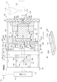
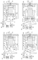
現在、多くの樹脂製品が射出成形によって製作されている。一般的な射出成形は、射出装置で溶融した樹脂を、閉じた金型内に高圧で射出充填し、金型内で冷却・固化させた後に製品を取り出す工程を踏む。図11(A)には、従来の一般的な射出成形装置の構造の一例が示されており、図11(B)には、製品離型時の様子が示され、図11(C)には製品の外観斜視図が示されている。図11(A)及び(B)に示すように、射出成形装置300は、金型が固定型304と可動型316に分割可能な構造となっており、前記固定型304は固定側取付板302に支持されており、前記可動型316は、脚部314を介して可動側取付板312に支持されている。前記固定側取付板302には、図示しない射出装置のノズルから射出される樹脂330の通路となるスプルブッシュ306が設けられており、前記固定型304には、前記スプルブッシュ306と接続するランナー308及びゲート310A,310Bが設けられている。
Currently, many resin products are manufactured by injection molding. In general injection molding, resin melted by an injection apparatus is injected and filled at high pressure in a closed mold, and after cooling and solidifying in the mold, a product is taken out. FIG. 11 (A) shows an example of the structure of a conventional general injection molding apparatus, FIG. 11 (B) shows the state at the time of product release, and FIG. 11 (C) shows. Is an external perspective view of the product. As shown in FIGS. 11A and 11B, the
また、前記可動型316には、前記ゲート310A,310Bを介して溶融状態の樹脂330が射出されるキャビティCが形成されている。前記可動型316と可動側取付板312の間には、前記脚部314によってスペース318が形成されており、該スペース318内に、前記可動型316と可動側取付板312の間で進退可能なスライドベース322が配置されている。該スライドベース322は、一方の主面322Aと前記可動型316との間に設けられたスプリング320によって、前記可動側取付板312側へ付勢されている。更に前記主面322Aには、前記可動型316を貫通して前記キャビティCに達する突出しピン326A,326Bの一端が固定されている。該スライドベース322は、図11(B)に示すように型開き状態で、前記可動側取付板312に設けられた貫通孔312Aを貫通する突出しロッド328の先端328Aによって主面322B側を押し出すことで、製品340を押し出して離型する。当該射出成形装置300においては、図11(A)に示すように、固定型304と可動型316を閉じた状態で、溶融状態の樹脂330を射出し、冷却・固化させた後に、図11(B)に示すように製品340、ランナーを離型する。
The
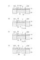
図12(A-1)〜(A-4)には、前記射出成形装置300によるキャビティC内の樹脂330の充填状況が模式的に示されている。図12(A-1)に示すように、2点ゲートより樹脂330が入り、図12(A-2)及び(A-3)に示すように、徐々に中央に樹脂330が近付いて先端部332から結合し、最終的には、図12(A-4)に示すように樹脂330の全体が融合する。このとき、キャビティC内では、樹脂330が前記キャビティCの中央に進行する段階で、樹脂330の表面が空気に触れて薄い固化層が形成され、それが結合するため、図12(A-4)及び図11(C)に示すように、製品340の表面には、略V字状溝のウエルドライン342が現れる。
FIGS. 12A-1 to 12A-4 schematically show the filling state of the
前記ウエルドラインは、射出成形品の欠点の一つであり、前記射出成形装置300のように、ゲートが2箇所以上の金型を利用した場合に現れるが、ゲートが1箇所であっても、製品に穴部やボス部がある場合には現れる。例えば、図13(C)に示すように、ボス部362を備えた製品360を形成する場合には、図13(A-1)〜(A-3)及び図13(B-1)〜(B-3)に示すように、キャビティCは、前記ボス部362を形成するための成形穴352を備えた形状となり、前記成形穴352にボス穴形成用コア354を配置した状態で、樹脂330を充填する。このようなキャビティCの形状にあっては、樹脂330は、図13(A-1)〜(A-3)及び図13(B-1)〜(B-3)に矢印F13で示すように充填され、成形穴352の環状部で二手に分かれた後、先端部332から合流するため、製品360のボス部362にウエルドライン364が現れる。
The weld line is one of the disadvantages of injection molded products, and appears when a gate uses two or more molds as in the
前記ウエルドラインは、上述したボス部のほか、製品の穴部にも現れるが、これら穴部やボス部は、製品の取り付け等に使用されるため、力が掛かり破損しやすい部分にウエルドラインが存在することになり、強度が不足するという不都合がある。特に、ガラス繊維入りの材料を用いた場合にあっては、左右から流れ込んだ樹脂が融合する部分において、ガラス繊維が一方向に配列されてしまうため、ガラス強化プラスチックのウエルドライン分の強度が半減してしまう。更に、流動する樹脂の先端部分には、ガラス繊維のみの層が形成されるため、材料が合流する部分では、実際には樹脂が融合しておらず、一層の強度不足の原因になるというおそれがある。 In addition to the bosses described above, the weld line also appears in product holes. However, these holes and bosses are used for product installation and the like. There is an inconvenience that the strength is insufficient. In particular, when glass-filled materials are used, the glass fiber is aligned in one direction at the part where the resin that flows from the left and right is fused, so the strength of the weld line of glass-reinforced plastic is halved. Resulting in. Furthermore, since a layer made only of glass fibers is formed at the tip portion of the flowing resin, the resin is not actually fused at the portion where the materials merge, which may cause a further lack of strength. There is.
前記ウエルドライン部の強度不足を解消するために、従来は、ボス部や穴部に金属のネジを埋め込み成形する等の処理が施されている。また、多点ゲートの場合は、ウエルドライン発生箇所は製品の中央部となり致命的な欠陥になりやすいため、それを避けるためにゲートの配置の考慮や数量の制限,あるいは、肉厚に成形して強度を向上させることで対応している。 In order to eliminate the insufficient strength of the weld line part, conventionally, a process such as embedding a metal screw in a boss part or a hole part is performed. In the case of multi-point gates, the weld line is located in the center of the product and is prone to fatal defects. Therefore, in order to avoid this, the gate arrangement must be considered, the quantity should be limited, or the thickness should be formed. To improve the strength.
また、上述したウエルドラインの発生のほか、上述した従来の一般的な射出成形で製作される樹脂製品は、冷却固化の段階で収縮してヒケやボイドを発生するという不都合もある。ヒケやボイドの発生を防止する手段としては、本願出願人が、特願2009−110173において提案した射出成形装置を用いた成形方法がある。該成形法を、ここではIMP(インモールドプレッシング)工法と称して以降の説明を行う。前記特願2009− In addition to the occurrence of the above-described weld line, the resin product manufactured by the conventional general injection molding described above has a disadvantage that shrinkage and voids are generated at the stage of cooling and solidification. As means for preventing the occurrence of sink marks and voids, there is a molding method using the injection molding apparatus proposed by the present applicant in Japanese Patent Application No. 2009-110173. This molding method is referred to herein as an IMP (in-mold pressing) method and will be described below. Japanese Patent Application No. 2009-
上述したウエルドラインの発生のほか、上述した従来の射出成形で製作される樹脂製品は、冷却固化の段階で収縮してヒケやボイドを発生するという不都合もある。ヒケやボイドの発生を防止するために、本願出願人が、特願2009−110173(特許文献1)において提案した射出成形装置を用いた成形方法がある。該成形法を、ここではIMP(インモールドプレッシング)工法と称して以降の説明を行う。前記特願2009−110173の射出成形装置は、金型のパーティングが開いた状態で樹脂を射出する従来の射出圧縮成形にかかる不都合(樹脂漏れや充填不足など)を改善するために開発されたものであって、図14に、その装置構成及びIMP工法の概略が示されている。図14(A)に示す射出成形装置400の金型部分は、固定側取付板402に固定された固定型404と、可動側取付板410に支持された可動型412と、該可動型412に形成された成形穴418内をスライド可能であって圧力センサ424が設けられたスライドコア420と、前記可動側取付板410に固定された脚部414と、該脚部414と前記可動型412の間に配置されたスペーサ416などにより構成されている。前記可動側取付板410は、直圧式又はトグル式などの図示しない型締め機構より、固定側取付板402に向けてストローク可能となっている。
In addition to the occurrence of the weld line described above, the resin product manufactured by the conventional injection molding described above also has a disadvantage that shrinkage and voids are generated at the stage of cooling and solidification. In order to prevent the occurrence of sink marks and voids, there is a molding method using an injection molding apparatus proposed by the present applicant in Japanese Patent Application No. 2009-110173 (Patent Document 1). This molding method is referred to herein as an IMP (in-mold pressing) method and will be described below. The injection molding apparatus of the Japanese Patent Application No. 2009-110173 was developed to improve inconveniences (such as resin leakage and insufficient filling) of conventional injection compression molding in which resin is injected with the parting of the mold open. FIG. 14 shows the outline of the apparatus configuration and the IMP method. The mold part of the
図14(B)に示すように、IMP工法では、固定型404と可動型412を高圧で閉じた状態で樹脂430を射出し、その後、スペーサ416を図示しない駆動機構により可動型412のストローク方向と直交する方向に引き抜く。そして、引き抜きによって生じたスペース分だけ、前記可動側取付板410及びスライドベース422を介してスライドコア420を成形穴418内でスライドさせ、キャビティCの容積の圧縮(再型締め)を行うことで、ヒケやボイドの発生を抑制する構成となっている。
As shown in FIG. 14B, in the IMP method, the
しかしながら、以上のような背景技術には、次のような不都合がある。まず、上述した一般的な射出成形装置300を利用した成形では、ウエルドライン部の強度不足を解消するために、製品の穴部やボス部に金属のネジを埋め込み成形したり、ゲート位置を変更したりする必要があり、成形工程やゲート構造が複雑になるという不都合がある。また、ウエルドラインの発生のほか、樹脂の材質や金型構造,製品形状,成形条件等によっては、図12(B-1)〜(B-4)に示すように、ジェッティングが発生する。多くの場合、ジェッティング解消については、ゲート位置を変更することにより対応し、ゲート位置にも制約がある場合には、成形条件で対応することとなるが、成形条件での対応には限界があるという不都合がある。
However, the background art as described above has the following disadvantages. First, in the molding using the general
一方、前記図14に示す射出成形装置400を利用したIMP工法では、型締め機構を利用した高圧でパーティングを閉じた状態で射出できるため、成形圧縮できる製品形状に自由度があり、肉厚製品や偏肉部分がある製品を高精度・ボイドレスで加工できるなどの利点があるものの、
(1)金型側面にスペーサを配置する必要があるため、金型構造が複雑になり、耐久性の低下やコストの向上につながる,
(2)スペーサを引き抜くために型締め圧を減圧やゼロにする必要があり、パーティングを常に高圧で型締めすることができず、パーティングバリが発生することがある,
(3)型締め圧力を利用してスライドコアを移動させるため、スライドコア専用の動きや制御を行うのが困難である,
(4)ウエルドライン部の強度不足解消やジェッティング解消については考慮されていない,といった不都合がある。
On the other hand, in the IMP method using the
(1) Since it is necessary to place spacers on the side of the mold, the mold structure becomes complicated, leading to a decrease in durability and an increase in cost.
(2) The mold clamping pressure needs to be reduced or zero to pull out the spacer, and the parting cannot always be clamped at a high pressure and parting burr may occur.
(3) Because the slide core is moved using the clamping pressure, it is difficult to perform the movement and control dedicated to the slide core.
(4) There is an inconvenience that the lack of strength in the weld line and the elimination of jetting are not considered.
本発明は、以上のような点に着目したもので、金型内に樹脂を射出して成形するにあたり、ウエルドライン部の強度不足やジェッティングを解消し、ガラス繊維入りの材料を使用した場合であっても、ガラス繊維浮きを解消することができる射出成形装置及び射出成形方法を提供することを、その目的とする。他の目的は、前記ウエルドライン部の強度不足,ジェッティング,ガラス繊維浮きの解消とともに、ボイド発生も解消可能な射出成形装置及び射出成形方法を提供することである。 The present invention pays attention to the above points, and when injecting resin into a mold and molding, the lack of strength of the weld line part and jetting are eliminated, and a material containing glass fiber is used. Even so, an object of the present invention is to provide an injection molding apparatus and an injection molding method capable of eliminating glass fiber floating. Another object of the present invention is to provide an injection molding apparatus and an injection molding method capable of eliminating the void generation as well as the lack of strength of the weld line portion, jetting and glass fiber floating.
本発明の射出成形装置は、可動側取付板に支持される可動型と、固定側取付板に支持される固定型の端面を当接させたときに、溶融樹脂が射出充填されるキャビティが形成される金型と、前記キャビティに溶融樹脂を射出充填する射出機構と、前記可動側取付板を固定側取付板に対してストロークさせて金型を開閉するとともに、前記射出機構による溶融樹脂の射出充填時に、金型のパーティングを高圧型締めする型締め機構と、前記可動型に前記ストローク方向に延長形成され、前記固定型に対向する端面に開口するとともに、該端面に前記固定型を当接させたときに、前記キャビティの少なくとも一部を形成する一つ以上の成形穴と、前記成形穴に一部が収容されており、該成形穴に沿って進退可能なスライドコアと、前記金型を閉じた状態のまま、前記スライドコアを前記成形穴に沿って進退可能に駆動し、前記成形穴の容積を変化させるスライドコア進退機構と、前記キャビティ内への溶融樹脂の射出状況に応じて前記スライドコア進退機構を駆動する制御手段と、前記キャビティから射出成形後の製品を押し出して離型する離型手段と、を備えるとともに、前記制御手段は、前記キャビティへの溶融樹脂の射出開始から所定時間経過までは、前記成形穴の容積を一定に保ち、所定時間が経過してから射出完了までの間は、前記成形穴の容積が徐々に拡張するように、前記スライドコア進退機構を制御することを特徴とする。 The injection molding apparatus of the present invention forms a cavity into which molten resin is injected and filled when the movable mold supported by the movable mounting plate and the end face of the fixed mold supported by the stationary mounting plate are brought into contact with each other. A mold to be molded, an injection mechanism for injecting and filling molten resin into the cavity, and opening and closing the mold by causing the movable side mounting plate to stroke with respect to the fixed side mounting plate, and injection of the molten resin by the injection mechanism At the time of filling, a mold clamping mechanism for clamping the parting of the mold with a high-pressure mold, and an extension formed in the stroke direction on the movable mold, opening at an end surface facing the fixed mold, and applying the fixed mold to the end surface One or more molding holes forming at least a part of the cavity when contacted, a slide core partly accommodated in the molding hole and capable of moving forward and backward along the molding hole, and the gold Closed mold In this state, the slide core is driven so as to be able to advance and retreat along the molding hole, and a slide core advance / retreat mechanism that changes the volume of the molding hole, and the slide core according to the injection state of the molten resin into the cavity A control means for driving the advance / retreat mechanism, and a release means for extruding the product after injection molding from the cavity, and the control means has passed a predetermined time from the start of injection of the molten resin into the cavity. Until the injection hole is maintained until the injection hole is completed after a predetermined time elapses, and the slide core advance / retreat mechanism is controlled so that the volume of the formation hole gradually expands. Features.
主要な形態の一つは、前記キャビティ内に射出される溶融樹脂が、該キャビティ内の一箇所以上で合流するとともに、前記制御手段は、合流した溶融樹脂が密着した後に、前記成形穴の容積を拡張する方向に前記スライドコア進退機構を駆動させることを特徴とする。他の形態は、前記キャビティが、ボス部ないし凹部を有する製品に対応した形状であること,あるいは、前記射出機構から複数のゲート口を介して前記キャビティに溶融樹脂が射出されることを特徴とする請求項1又は2記載の射出成形装置。
One of the main forms is that the molten resin injected into the cavity is merged at one or more locations in the cavity, and the control means is configured so that the volume of the molding hole is increased after the merged molten resin is in close contact. The slide core advancing / retreating mechanism is driven in a direction in which the slide core is expanded. In another embodiment, the cavity has a shape corresponding to a product having a boss or a recess, or the molten resin is injected into the cavity from the injection mechanism through a plurality of gate ports. The injection molding apparatus according to
更に他の形態は、前記スライドコア進退機構が、前記可動側取付板と可動型の間に配置されており、前記スライドコアが進退するスペースを形成する脚部と、該脚部によって形成されたスペース内に配置されており、主面の一方が前記スライドコアの後端に取り付けられたスライドベースと、前記可動側取付板を前記進退方向に貫通し、一端が前記スライドベースの他方の主面に当接可能な一つ以上の移動ピンと、該移動ピンの他端側に配置されており、前記移動ピンを前記進退方向に駆動する移動ピン駆動手段と、を備えたことを特徴とする。 In still another embodiment, the slide core advance / retreat mechanism is formed between the movable side mounting plate and the movable mold, and a leg portion that forms a space for the slide core to advance and retreat, and the leg portion. The slide base disposed in the space, one of the main surfaces is attached to the rear end of the slide core, and the movable side mounting plate penetrates in the advancing and retracting direction, and one end is the other main surface of the slide base One or more moving pins that can contact the moving pin, and a moving pin driving means that is disposed on the other end side of the moving pin and drives the moving pin in the forward / backward direction.
更に他の形態は、前記離型手段が、前記スライドベースを介して前記スライドコアを前方に押し出す突出しロッドと、該突出しロッドを前記進退方向に駆動する突出しロッド駆動手段と、を備えたことを特徴とする。更に他の形態は、前記制御手段は、前記成形穴の容積の拡張を停止した後に、前記スライドコアを前進させて前記成形穴の容積を圧縮することを特徴とする。 In still another embodiment, the releasing means includes a protruding rod that pushes the slide core forward through the slide base, and a protruding rod driving means that drives the protruding rod in the forward / backward direction. Features. In still another embodiment, the control means stops the expansion of the volume of the molding hole and then advances the slide core to compress the volume of the molding hole.
本発明の射出成形方法は、可動型と固定型の分割面に形成されるキャビティに溶融樹脂を射出充填し、冷却固化する射出成形方法であって、前記キャビティの少なくとも一部を形成する成形穴に、スライドコアの一部が前記可動型のストローク方向に進退可能に設けられており、型締め状態において前記スライドコアを前進させ、前記成形穴を所定の容積に縮小して維持する工程と、前記キャビティへの溶融樹脂の射出を開始する工程と、前記溶融樹脂の射出を開始してから所定時間経過の後に、前記スライドコアを徐々に後退させて、前記成形穴の容積を連続的に拡張する工程と、前記成形穴の容積拡張を停止する工程と、前記キャビティに射出充填された溶融樹脂の冷却を開始する工程と、冷却固化した製品を、型開きして離型する工程と、を含むことを特徴とする。 An injection molding method of the present invention is an injection molding method in which molten resin is injected and filled into a cavity formed on a dividing surface of a movable mold and a fixed mold, and is cooled and solidified, and a molding hole for forming at least a part of the cavity In addition, a part of the slide core is provided so as to be able to advance and retreat in the stroke direction of the movable mold, and the slide core is advanced in a mold clamping state, and the molding hole is reduced to a predetermined volume and maintained. A step of starting injection of molten resin into the cavity and a predetermined time after the injection of molten resin starts, the slide core is gradually retracted to continuously expand the volume of the molding hole. A step of stopping volume expansion of the molding hole, a step of starting cooling of the molten resin injected and filled in the cavity, and a step of opening the mold after releasing the cooled and solidified product , Characterized in that it comprises a.
主要な形態の一つは、前記キャビティ内に射出される溶融樹脂が、該キャビティ内の一箇所以上で合流するとともに、前記成形穴の容積を拡張する工程を、前記キャビティ内で合流した溶融樹脂が密着した後に開始することを特徴とする。他の形態は、前記冷却の開始の工程後に、前記スライドコアを前進させて、前記成形穴の容積を圧縮する工程,を含み、該圧縮工程の後に、冷却固化した製品を型開きして離型することを特徴とする。本発明の前記及び他の目的,特徴,利点は、以下の詳細な説明及び添付図面から明瞭になろう。 One of the main forms is that the molten resin injected into the cavity merges at one or more locations in the cavity and expands the volume of the molding hole. It starts after it adheres. In another embodiment, after the cooling start step, the slide core is advanced to compress the volume of the forming hole, and after the compression step, the cooled and solidified product is opened and separated. It is characterized by molding. The above and other objects, features and advantages of the present invention will become apparent from the following detailed description and the accompanying drawings.
本発明によれば、固定型と可動型の間に形成されるキャビティに射出された樹脂を成形するにあたり、前記キャビティの少なくとも一部を形成する成形穴の内部でスライド可能なスライドコアの進退により、射出開始から一定時間が経過するまでは、前記成形穴を所定の一定容積に維持し、前記一定時間が経過してから射出完了までは、スライドコアを徐々に後退させて成形穴の容積を連続的に拡張することとしたので、ウエルドライン部の強度不足やジェッティングが解消可能となり、ガラス繊維入りの材料を用いた場合であっても、ガラス繊維浮きを防止できるという効果がある。また、ゲート口より放射線状にガラス繊維が配向する性質を緩和し、全ての方向からの強度が安定し、ソリの抑制に繋がる。更に、必要に応じて、前記スライドコアの後退停止後に、該スライドコアを前進させて成形穴の容積を圧縮することで、前記ウエルドライン部の強度不足,ジェッティング,ガラス繊維浮きの解消に加えて、ボイドの発生を解消することも可能となる。 According to the present invention, when the resin injected into the cavity formed between the fixed mold and the movable mold is molded, the slide core is slidable in the molding hole that forms at least a part of the cavity. The molding hole is maintained at a predetermined constant volume until a predetermined time elapses from the start of injection, and the slide core is gradually retracted until the injection is completed after the certain time elapses to reduce the volume of the molding hole. Since the expansion is performed continuously, insufficient weld strength and jetting at the weld line portion can be eliminated, and even when a material containing glass fiber is used, there is an effect that glass fiber floating can be prevented. Moreover, the property which glass fiber orientates radially from a gate port is eased, the intensity | strength from all directions is stabilized, and it leads to suppression of a warp. Furthermore, if necessary, after the slide core is retracted and stopped, the slide core is advanced to compress the volume of the molding hole, thereby eliminating the lack of weld line strength, jetting, and glass fiber floating. Thus, it is possible to eliminate the generation of voids.
以下、本発明を実施するための形態を、実施例に基づいて詳細に説明する。 Hereinafter, the form for implementing this invention is demonstrated in detail based on an Example.
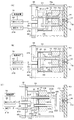
最初に、図1〜図4を参照しながら本発明の実施例1を説明する。図1(A)は本実施例の射出成形装置の全体構成を示す図,図1(B)は本実施例により成形される製品形状を示す外観斜視図である。図2は、本実施例の作用を示す図,図3は、本実施例による成形工程を示すフローチャート,図4は、本実施例の成形工程におけるキャビティ内の溶融樹脂の流れを示す模式図である。本実施例は、上述した一般的な射出成形に適用することで、ウエルドライン部の強度不足やジェッティングの解消を行うものであって、ガラス繊維入りの材料を利用した場合には、ガラス繊維浮きの解消も可能な構成となっている。なお、以下の説明中、必要に応じて、本実施例による射出成形方法を、IMM工法(インモールドムービング工法)と称する。
First,
図1(A)に示すように、本実施例の射出成形装置10は、固定型16と可動型32を含む金型12と、型締め機構70と、制御装置76と、スライドコア進退機構80と、射出装置110と、離型手段により構成されている。まず、金型12から説明すると、金型12の固定側は、固定側取付板14に固定型16が取り付けられており、該固定側取付板14をスプルブッシュ18が貫通している。前記固定型16には、前記スプルブッシュ18と連結するランナー20A,20B及びゲート22A,22Bが設けられている。前記スプルブッシュ18には、溶融状態の樹脂34を供給するために、後述する射出装置110のノズル118が接続される。前記固定側取付板14は、固定プレート60に支持されている。また、固定型16には、必要に応じて、後述する可動側の成形穴36に対応する面に沿って、冷却液を流通させる冷却孔(図示せず)が設けられる。
As shown in FIG. 1A, the
一方、金型12の可動側は、可動側取付板26と、前端面が前記固定型16と対向する可動型32と、該可動型32を支持する脚部28とを有している。前記脚部28を可動側取付板26と可動型32の間に配置することで、後述するスライドコア38が進退可能なスペース30が形成される。前記可動型32には、該可動型32のストローク方向に延長形成された成形穴36が形成されており、該成形穴36は、前記可動型32の前端面を前記固定型16に当接させたときに、キャビティCを構成する。前記成形穴36には、該成形穴36に沿って進退可能なスライドコア38の一部が収容されている。該スライドコア38の後端面38Bは、前記スペース30内に露出しており、第1プレート40Aと第2プレート40Bからなるスライドベース40に固定されている。前記可動側取付板26には、貫通孔26A,26Bが設けられており、後述するスライドコア進退機構80の移動ピン86が前記貫通孔26Aを貫通し、移動ピン88が前記貫通孔26Bを貫通している。
On the other hand, the movable side of the
前記スライドベース40と前記可動型32の間には、必要に応じて図示しないスプリングを設け、前記スライドベース40を常に可動側取付板26に向けて付勢するようにしてもよい。後述するスライドコア進退機構80により、前記スライドベース40を矢印F1a方向にストロークさせると、スライドコア38が成形穴36内で移動してキャビティCの容積を圧縮し、スライドベース40が矢印F1b方向に後退可能にすると、キャビティCの容積を拡張することができる。更に、前記可動側取付板26の略中央部には、他の貫通孔26Cが形成されており、後述する移動プレート66の背面側に設けられた油圧シリンダ50により駆動される突出しロッド46が貫通可能となっている。そして、前記油圧シリンダ50の駆動により、突出しロッド46の先端46Aで前記スライドベース40を押し出すことによってスライドコア38を前進させて、キャビティC内で成形された製品を押し出し離型する。すなわち、前記スライドコア38は、キャビティCの容積の調節を行うとともに、前記スライドベース40,突出しロッド46,油圧シリンダ50とともに、製品の離型手段を構成している。前記油圧シリンダ50は、後述する制御装置76に接続されている。
A spring (not shown) may be provided between the
次に、型締め機構70について説明する。型締め機構70は、前記可動側取付板26を固定側取付板14に対してストロークさせて金型12を開閉するとともに、後述する射出機構110による溶融状態の樹脂34の射出充填時に、金型12のパーティングを高圧型締めするものである。本実施例では、型締め機構70として、トグル式の型締め機構を採用している。該トグル式の型締め機構においては、一対の固定プレート60,62の間に移動プレート66を配置し、該移動プレート66は、前記一対の固定プレート60,62間に設けられた複数のガイドロッド64に沿って、矢印F1a,F1b方向にストロークさせる。前記移動プレート66は、複数のリンク72A〜72Fからなるカム機構を介して、油圧モータ74のロッド73に接続されている。該ロッド73は、前記固定プレート62を貫通している。前記固定型16が支持された固定側取付板14は、前記固定プレート60に固定され、可動型32を支持した可動側取付板26は、後述するスライドコア進退機構80を介して、前記移動プレート66に支持される。
Next, the
次に、スライドコア進退機構80について説明する。スライドコア進退機構80は、前記金型12を閉じた状態のまま、前記スライドコア38を前記成形穴36に沿って進退可能に駆動し、成形穴36の容積を変化させるものであって、脚部28,スライドベース40,固定台82,移動ピン86及び88,スペーサ90,サーボモータ98などにより構成されている。このうち、前記脚部28は、上述した通り、前記可動側取付板26と可動型32の間に配置され、両端がそれぞれ可動側取付板26と可動型32に固定されており、前記スライドコア38が進退するスペース30を形成するものであり、スライドベース40についても上述した通りである。前記固定台80は、図1(A)に示すように、上面82A及び側面82Bからなる断面略コ字状であって、側面82Bの縁が前記移動プレート66に固定されており、前記上面82Aに前記可動側取付板26が固定されている。前記上面82Aには、前記可動側取付板26の貫通孔26A〜26Cに対応する位置に、貫通孔84A〜84Cが形成されており、貫通孔26A及び84Aを移動ピン86が貫通可能であり、貫通孔26B及び84Bを移動ピン88が貫通可能であり、貫通孔26C及び84Cを突出しロッド46が貫通可能となっている。
Next, the slide core advance /
前記移動ピン86,88の先端86A,88A側は、前記スライドベース40の背面側に当接可能となっており、移動ピン86,88の後端側には、ローラ86B,88Bが設けられている。また、前記固定台82の内側には、前記移動プレート66の主面に沿って、前記可動側取付板26のストローク方向(図1の矢印F1a,F1b方向)と略直交する方向にスライド可能なスペーサ90が配置されている。該スペーサ90は、厚肉部92と薄肉部94が、斜面96A,96Bを挟んで交互に形成された形状となっており、前記厚肉部92と薄肉部94の表面は、移動プレート66の主面と略平行となっている。前記スペーサ90は、例えば、軸100を介してサーボモータ98に接続され、該サーボモータ98によって駆動される。該サーボモータ98は、上述した制御装置76に接続されている。制御装置76によってサーボモータ98を駆動し、スペーサ90をスライドさせることにより、ローラ86B,88Bがスペーサ90の厚肉部92,斜面96A及び96B,薄肉部94のいずれの位置に接するかに応じて、移動ピン86,88の後退量(ないし前進量),ひいては、スライドコア38の後退量(ないし前進量)を調節することが可能となる。なお、本実施例では、制御のしやすさの観点からサーボモータ98を利用しているが、他の公知の各種の駆動手段を利用してもよい。
The distal ends 86A and 88A of the moving
次に、前記制御装置76について説明する。制御装置76は、型締め機構70の油圧モータ74と突出しロッド46の油圧シリンダ50の駆動を制御するほか、前記キャビティC内への溶融樹脂の射出状況に応じて、前記スライドコア進退機構80のサーボモータ98の駆動も制御する。具体的には、前記キャビティCへの樹脂34の射出開始から所定の一定時間が経過するまでは、前記成形穴36の容積が縮小された状態で一定に保ち、所定時間が経過してから射出完了までの間には、成形穴36の容積が徐々に拡張するように、前記サーボモータ98の駆動を制御する。本実施例では、2つのゲート22A、22BからキャビティCに樹脂34が射出される2点ゲート構造をとっているため、前記制御手段76は、キャビティC内で合流した樹脂34が完全に密着するまでは、キャビティ容積が縮小した状態を保ち、樹脂34の合流・密着後に、キャビティCの容積が拡張するように、スライドコア38を徐々に後退させるという制御を行う。
Next, the
次に、射出装置110について説明する。射出装置110は、ホッパ114から投入された成形材料をシリンダ112により溶融させ、射出機構116によって前記シリンダ112の先端のノズル118から、前記金型12のキャビティCに、スプル18A,ランナー20A及び20B,ゲート22A及び22Bを介して溶融状態の樹脂34を射出充填するもので、その構造は公知である。
Next, the
次に、図2〜図4も参照しながら、本実施例の作用を説明する。まず、型締め機構70の油圧モータ74の駆動により、可動側型板26を図1の矢印F1aに示す方向に移動させて金型12を型締めする(図3のステップS10)。次に、スライドコア進退機構80のサーボモータ98の駆動により、スペーサ90を図2(A)に示す矢印F2a方向に押込んだ状態,すなわち、移動ピン86,88のローラ86B,88Bをスペーサ90の厚肉部92に接触させて、スライドコア38を成形穴36内で前進させて(ステップS12)、キャビティCの容積を所定の初期設定容積に維持した状態で、前記射出装置110からの樹脂34の射出を開始する(ステップS14)。このときの状態が、図4(A)に示されている。
Next, the operation of this embodiment will be described with reference to FIGS. First, by driving the
そして、図4(B)に示すように、キャビティCに射出された樹脂34の先端部34Aから合流した樹脂が密着するまで一定時間の経過を待ったら(ステップS16)、スライドコア進退機構80の駆動により、射出成形圧力と同調してスペーサ90を図2(B)に矢印F2bで示す方向に徐々に後退させる。スペーサ90を矢印F2b方向に後退させると、厚肉部92に接していたローラ86B,88Bが、薄肉部94へ向けて斜面96A,96Bを移動可能となるため、樹脂34の射出圧力により、スライドコア38が成形穴36に沿って矢印F1b方向に後退を開始する(ステップS18,図4(B)及び(C)))。そして、図4(D)に示すように、キャビティCが所定の容積まで拡張されたらスライドコア38の後退を停止させ(ステップS20)、次いで、樹脂34の射出を停止する(ステップS22)。
Then, as shown in FIG. 4B, when a certain period of time has elapsed until the resin merged from the
その後は、冷却を行い(ステップS24)、冷却が完了したら、型締め機構70の油圧モータ74を駆動させて型開きし(ステップS26),図2(C)に示すように、離型手段の突出しロッド46を油圧シリンダ50の駆動により突き出すことで、スライドベース40を介し、スライドコア38により製品120を離型する(ステップS28)。その後は、続けて成形を行うのであれば(ステップS30のYes),前記ステップS10に戻り、ステップS12〜S28までを繰り返し、成形を行わない場合は(ステップS30のNo)、終了する。以上の工程によって得られた製品120は、図1(B)に示すように、製品が薄い状況でウエルドラインが接合することから、接合時の射出圧力が高く、接合強度も高まり、その後のスライドコア38の移動により、ウエルドライン124がない状況(ほとんどない状況を含む)を作り出すことができ、ウエルドライン部の強度不足を解消することが可能となる。また、ガラス繊維入りの材料を用いた場合であっても、ガラス繊維浮きを防止できるという効果がある。更に、ゲート口より放射線状にガラス繊維が配向する性質を緩和し、全ての方向からの強度が安定し、ソリの抑制に繋がる。樹脂の射出成形の場合、特にガラス繊維含有の材料を用いた場合には、ゲート口から流れ出た材料は放射線状に広がり、樹脂の高分子やガラス繊維が放射線状に配列する。そのことにより、製品でゲート口から遠ざかる方向の製品強度は非常に強く、逆にその方向から90度の方向では、極端に強度不足を招くことになる。上述した本実施例のIMM工法によれば、薄肉製品を作る段階では配向は発生するが、その後、スライドコア38を後退させて製品を広げる段階になると、樹脂34の流れる方向が90度変化する事から、配向のランダムな製品ができる。このため、製品120の強度にむらがなく、全ての方向で安定した強度が得られる。また、配向がないことから、製品120のソリの問題にも有効である。
Thereafter, cooling is performed (step S24). When cooling is completed, the
このように、実施例1によれば、固定型16と可動型32の間に形成されるキャビティCに射出された樹脂34を成形するにあたり、前記キャビティCを形成する成形穴36の内部でのスライドコア38の進退により、樹脂34の射出開始から一定時間経過後までは、キャビティCを一定容積に維持し、一定時間経過後から射出完了までは、スライドコア38を徐々に後退させてキャビティCの容積を徐々に拡張することとした。このため、次のような効果が得られる。
(1)製品120のウエルドライン124を消すか、あっても、極わずかなラインにできるため、ウエルドライン部の強度不足を解消できる。
(2)射出時にジェッティングの発生しない形状にし、そこから実際の製品120の形状にキャビティCを広げていくため、全くジェッティングが発生しない優れた外観の製品120を作り出すことができる。
(3)本実施例のIMM工法では、キャビティCの容積を徐々に広げていくため、最初に強い射出圧力が樹脂34に加えられ、その圧力を維持した状態でキャビティCを製品120の形状まで拡張するため、樹脂34としてガラス繊維入りの材料を用いた場合であっても、ガラス繊維浮きの少ない外観に優れた製品を得ることができる。また、ゲート口122A,122Bより放射線状にガラス繊維が配向する性質を緩和し、全ての方向からの強度安定になり、ソリの抑制につながる。
(4)通常、ガラス繊維入りの樹脂34を用いた場合は、ジェッティングが生じると製品120の全体にウエルドラインが生じているのと同じことになるが、本実施例のIMM工法によれば、ジェッティングが全く生じないため、強度の向上も図ることができる。
As described above, according to the first embodiment, when the
(1) Even if the
(2) Since the cavity C is expanded to the shape of the
(3) In the IMM method of the present embodiment, since the volume of the cavity C is gradually expanded, a strong injection pressure is first applied to the
(4) Normally, when the
次に、図5〜図7を参照しながら本発明の実施例2を説明する。なお、上述した実施例1と同一ないし対応する構成要素には同一の符号を用いることとする(以下の実施例についても同様)。上述した実施例1は、2点ゲート構造を採用し、キャビティ内で樹脂が合流する金型構成の例であるが、本実施例は、ゲートが一箇所であり、かつ、キャビティ内で樹脂が合流する形状の金型を用いた例である。図5(A)は、本実施例の射出成形装置の主要部を示す図,図5(B)は本実施例により成形される製品形状を示す外観斜視図である。図6は、本実施例の作用を示す図である。図7は、本実施例の成形工程におけるキャビティ内の溶融樹脂の流れを示す図であり、(A-1)〜(A-3)は平面図,(B-1)〜(B-3)は前記(A-1)〜(A-3)を#A−#A線に沿って切断し矢印方向に見た断面図である。
Next,
本実施例の射出成形装置200においても、金型202は、固定型204と可動型206に分割構成されている。前記固定型204側には、スプルブッシュ18と接続するランナー20Bとゲート22Bのみが形成された1点ゲート構造となっている。一方、可動型206側には、図5(B)に示す製品220の本体部222に相当するキャビティCと、前記製品220のボス部224に相当し前記キャビティCの一部を構成する成形穴208と、突出しロッド214が貫通する貫通孔209が形成されている。前記成形穴208には、略円筒状のスライドコア210の一部が収容されている。該スライドコア210は、前記成形穴208の容積を増減するためのもので、一方の端部210A側が成形穴208内に収容され、他方の端部210Bがスライドベース40の第1プレート40Aに固定され、該固定部分が第2プレート40Bにより覆われている。
Also in the
また、本実施例では、前記スライドベース40と移動プレート66の間に、他のスライドベース42が配置されている。該スライドベース42は、第1プレート42Aと第2プレート42Bにより構成され、前記スライドベース40とは独立して矢印F5方向に進退可能となっている。前記スライドベース42には、貫通孔44A,44Bが形成されており、一方の貫通孔44Aを、前記ボス穴形成用コア212が貫通し、その端部212Bが前記移動プレート66に固定されている。また、他方の貫通孔44Bには、移動ピン216が挿通されている。該移動ピン216は、移動プレート66も貫通し、一方の端部216Aが前記スライドベース40に接触可能となっており、他方の端部側が油圧モータ218に接続されている。該油圧モータ218は、前記制御装置76に接続されており、該制御装置76によって、移動ピン216の進退が制御されている。なお、本実施例では、移動ピン216の駆動手段として油圧モータ218を用いたが、上述した実施例1と同様にスペーサ90やサーボモータ98を利用した機構としてもよい。更に、前記スライドベース42の第1プレート42Aには、前記突出しロッド214の一方の端部214Bが固定され、該固定部分が第2プレート42Bにより覆われている。前記突出しロッド214は、スライドベース42が移動プレート66に着座した状態において、その先端214Aが、キャビティCの本体部分と面一となるような長さに設定されている。油圧シリンダ50の駆動により突出しロッド46が前進し、該突出しロッド46の先端46Aによってスライドベース42が押し出されると、それに伴って突出しロッド214が前進し、キャビティC内で成形された製品200を金型202から押し出し離型する。
In this embodiment, another
次に、図6及び図7も参照しながら本実施例の作用を説明する。まず、図示しない型締機構(例えば、実施例1と同様の型締め機構70)の駆動により、可動側型板206を図6の矢印F6aに示す方向に移動させて金型202を型締めする。この型締め状態において、前記ボス穴成形用コア212の先端212Aは、固定型204の端面に当接している。次に、油圧モータ218の駆動により、移動ピン216を前進させて、スライドベース40及びスライドコア210を前進させ、成形穴208の容積を所定の初期設定容積に縮小し、その状態を維持したままで、図示しない射出装置からキャビティCへの樹脂34の射出を開始する。このときの状態が、図6(A)及び図7(A-1)及び(B-1)に示されている。
Next, the operation of this embodiment will be described with reference to FIGS. First, by driving a mold clamping mechanism (not shown) (for example, a
キャビティCに射出された樹脂34は、図7に矢印F7で示すように進行するが、ボス穴形成用コア212まで到達すると二手に分かれ、その先端部34Aは、2方向から合流する。そして、前記先端部34Aから合流した樹脂34が完全に密着するまで一定時間の経過を待ったら、油圧モータ218の駆動により、移動ピン216を図6(B)に矢印F6b方向に後退させる。すると、樹脂34の射出圧力によりスライドコア210が成形穴208に沿って矢印F6b方向に後退を開始する(図7(A-2)及び(B-2))。そして、図7(A-3)及び(B-3)に示すように、成形穴208が所定の容積まで拡張されたら、スライドコア210の後退を停止させ、次いで、樹脂34の射出を停止する。
The
その後は、冷却を行い、冷却が完了したら、型締め機構により型開きし、図6(C)に示すように、離型手段の突出しロッド46を油圧シリンダ50の駆動により突き出すことで、スライドベース40,42が矢印F6a方向に前進し、スライドコア210の先端210Aと、突出しロッド216の先端216Aによって、製品220を押し出し離型する。その後は、必要に応じて、上述した動作を繰り返して成形を行う。以上の工程によって得られた製品220は、図5(B)に示すように、ボス部224のウエルドライン228がないか、あってもごく浅いものであり、ウエルドライン部の強度不足を解消することが可能となる。本実施例のように、ゲートが1箇所であってもキャビティC内で樹脂が合流する構造であれば、上述した実施例1と同様に、ウエルドライン部の強度不足,ジェッティング,ガラス繊維浮きの解消などが可能である。
Thereafter, cooling is performed. When the cooling is completed, the mold is opened by a mold clamping mechanism, and the protruding
次に、図8及び図9を参照しながら本発明の実施例3を説明する。上述した実施例1及び2は、主に、ウエルドライン部の強度不足,ジェッティング,ガラス繊維浮きの解消を目的とするIMM工法のみを行うものであるが、本実施例は、前記IMM工法に、上述したIMP工法を組み合わせることで、製品のボイドをなくすことも可能にした例である。図8は、本実施例の射出成形装置の全体構成と作用を示す図,図9は、本実施例による成形工程を示すフローチャートである。図8に示すように、本実施例で使用する射出成形装置は、上述した実施例1の射出成形装置10と同じ構成である。また、図9に示すように、型締め(ステップS10,図8(A))から、射出の停止(ステップS22)までの工程も、前記実施例1と同様である。
Next,
本実施例においては、図8(B)に示す射出停止後、図示しない冷却機構により金型12の冷却を開始し(図9のステップS50)、次いで、制御装置76にサーボモータ98を駆動させ、図8(C)に示すようにスペーサ90を矢印F2b方向にスライドさせることで、移動ピン86,88のローラ86B,88Bがスペーサ90の厚肉部92に乗り上げ、移動ピン86,88が同図に矢印F8aで示す方向に前進し、圧縮を開始する(ステップS52)。すると、該移動ピン86,88によりスライドベース40を介してスライドコア38が矢印F8a方向に前進し、キャビティCを圧縮するため、図8(B)に示すようなボイド130を消すことができる。その後、冷却が完了したら(ステップS54)、図8(D)に示すように型開きし(ステップS26)、製品120を突出し・離型する(ステップS28)。ステップS26〜ステップS30までは、上述した実施例1と同様である。
In this embodiment, after the injection is stopped as shown in FIG. 8B, cooling of the
本実施例3のように、IMM工法とIMP工法を組み合わせることにより、次のような効果が得られる。
(1)IMP工法のみを行った場合、ボイド130を消すことはできるが、それによって製品120の内部に応力がたまりやすいことが分かっている。この応力は、冷却時に開放しようとすると製品内部にクラックという形で現れるが、このクラックは、製品内部に存在する湯シワ(ある意味でのウエルドライン)を起点として起こるものである。これに対し、本実施例では、前記IMP工法と実施例1のIMM工法を組み合わせることにより、製品内部に潜む強度のアンバランスを極力防ぎ、均一した優れた強度安定性を得ることが可能となる。例えば、ゲート1箇所でウエルドラインなし製品の強度を100とした場合、ゲート2箇所の通常成形では強度が50しか得られないのに対し、本実施例のIMM工法とIMP工法の組み合わせによれば、ゲート2箇所で強度75という試験結果が得られている。
The following effects can be obtained by combining the IMM method and the IMP method as in the third embodiment.
(1) When only the IMP method is performed, the void 130 can be eliminated, but it is known that stress easily accumulates inside the
(2)本実施例の工法を、例えば、実施例2に示す射出成形装置200で行うことにより、ウエルドライン部強度不足やジェッティングの解消部位と、圧縮部位を任意に設定できることから、様々な製品形状に対応可能となる。
(3)背景技術のIMP工法に比べ、金型側面にスペーサを配置する必要がないため、金型構造が単純になり、耐久性向上やコスト削減にも効果が得られる。
(4)前記背景技術のIMP工法と比べ、金型側面に配置したスペーサを引き抜く必要がないため、型締め圧を減圧やゼロにする必要がなく、パーティングを常に高圧型締めしてパーティングバリの発生を防止することができる。
(5)射出した樹脂34を圧縮できるため、製品形状の自由度が増す,薄肉製品や、薄肉部分を含む偏肉製品にも対応できるという効果がある。
(6)前記背景技術のIMP工法では、型締め圧を利用した圧縮を掛けるのに対して、本実施例の組み合わせ工法では、IMM工法用のスライドコア圧縮機構80を、型締め機構70とは独立して外付けする機構であるため、キャビティC(ないし成形穴36)の容積圧縮や拡張のための専用の動作及び制御を行うことが可能である。
(2) By performing the construction method of the present embodiment with, for example, the
(3) Compared to the IMP method of the background art, it is not necessary to arrange a spacer on the side surface of the mold, so the mold structure is simplified, and the effect of improving durability and reducing costs can be obtained.
(4) Compared to the IMP method of the background art, it is not necessary to pull out the spacer arranged on the side of the mold, so there is no need to reduce the mold clamping pressure or zero, and the parting is always clamped with high pressure Generation of burrs can be prevented.
(5) Since the injected
(6) In the IMP method of the background art, compression using a mold clamping pressure is applied, whereas in the combination method of this embodiment, the slide
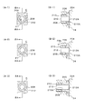
次に、図10(A)を参照しながら、本発明の実施例4を説明する。本実施例は、スライドコア進退機構の他の構成を示した例であり、その他の構成部分は、上述した実施例1と基本的には同様である。図10(A)に示すスライドコア進退機構250では、前記固定台80が、移動プレート66上に設けられたプレート252に固定されており、該プレート252上には、薄型油圧シリンダ254が設けられている。該薄型油圧シリンダ254は、前記制御装置76に接続されている。また、スライドコア38を進退させるための移動ピン86,88の後端側は、前記薄型油圧シリンダ254に接続されており、該薄型油圧シリンダ254によってキャビティCの容積の調整が行われる。本実施例では、型締め後、前記薄型油圧シリンダ254により移動ピン86,88を前進させてキャビティ容積を一定の縮小状態に保ち、射出された樹脂34がキャビティC内で完全に密着するのを待ってから、移動ピン86,88を徐々に後退させてキャビティ容積を拡張することで、上述した実施例1と同様の効果が得られる。また、必要に応じて、前記実施例3と同様に、射出完了後に、スライドコア38によりキャビティCを圧縮してボイドをなくすようにしてもよい。
Next,
次に、図10(B)及び(C)を参照しながら、本発明の実施例5を説明する。本実施例も、スライドコア進退機構の他の構成を示した例であり、その他の構成部分は、上述した実施例1と同様である。図10(B)は本実施例の射出成形装置の全体構成を示す図,図10(C)は、スライドベースを移動プレート66側から見た平面図である。本実施例のスライドコア進退機構260では、移動プレート66の上に固定されたプレート262に、大口径のネジ部材264が、該プレート262に対して回転可能に支持されている。一方、スライドコア40の裏面には、大口径のナット266が回転可能に取り付けられている。該ナット266の外周面には歯車部268が形成されている。また、前記スライドベース40の前面側にはモータ272が設けられており、該モータ272の出力軸は前記スライドベース40を貫通し、該出力軸の先端に設けられた歯車274と前記歯車部268には、ベルト270が掛けられている。従って、前記モータ272の駆動により、歯車274,ベルト270,歯車部268を介してナット266を回転させると、該ナット266に噛み合うネジ部材264がプレート262に固定されているため、スライドベース40が進退することとなる。なお、前記モータ272は、油圧モータ74とともに制御装置76に接続されている。
Next, Embodiment 5 of the present invention will be described with reference to FIGS. 10 (B) and 10 (C). The present embodiment is also an example showing another configuration of the slide core advance / retreat mechanism, and the other components are the same as those of the first embodiment described above. FIG. 10B is a diagram showing the overall configuration of the injection molding apparatus of the present embodiment, and FIG. 10C is a plan view of the slide base as viewed from the moving
本実施例では、型締め後、前記モータ272の駆動によりスライドベース40を前進させてキャビティ容積を一定の縮小状態に保ち、射出された樹脂34がキャビティC内で完全に密着するのを待ってから、前記モータ272の駆動によりスライドベース40及び移動ピン86,88を徐々に後退させてキャビティ容積を拡張する。また、前記実施例3と同様に、必要に応じて、射出完了後に、スライドコア38によりキャビティCを圧縮してボイドをなくすようにしてもよい。本実施例の効果は、上述した実施例1と同様である。
In this embodiment, after clamping the mold, the
なお、本発明は、上述した実施例に限定されるものではなく、本発明の要旨を逸脱しない範囲内において種々変更を加え得ることができる。例えば、以下のものも含まれる。
(1)前記実施例1では、固定型16における可動型32の成形穴36に対向する部分は平坦となっているが、製品の形状に応じて対応する成形凹凸部を形成することができる。他の実施例についても同様である。
(2)前記実施例1で示したスペーサ90とサーボモータ98を利用したスライドコア進退機構80や、実施例4のスライドコア進退機構250,実施例5のスライドコア進退機構260も一例であり、同様の効果を奏する範囲内で、適宜設計変更可能である。例えば、図10(D)に示す例のように、可動側型板26を貫通し、油圧シリンダ282A〜282Cによって駆動可能な3つの突出しピン280A〜280Cを設け、これら突出しピン280A〜280Cのいずれかを、スライドコアの押し出し手段として利用してもよい。また、前記実施例1においては、スライドベース40を第1プレート40Aと第2プレート40Bから構成することとしたが、これも一例であり、スライドベース40を構成するプレート数の増減によって、スライドコアの移動量を調節するようにしてもよい。
In addition, this invention is not limited to the Example mentioned above, A various change can be added in the range which does not deviate from the summary of this invention. For example, the following are also included.
(1) In the first embodiment, the portion of the fixed
(2) The slide core advance /
(3)前記実施例では、ゲートが1箇所又は2箇所の場合を例に挙げたが、これも一例であり、3点以上のゲートを有する構成にも本発明は適用可能である。
(4)前記実施例2では、ボス部224を有する製品220を成形する場合を例に挙げたが、これも一例であり、穴部や凹部を有する製品の場合のように、キャビティ内で樹脂が合流するような金型構造全般に対して、本発明は適用可能である。
(5)本発明は、例えば、ガラス繊維入りの樹脂を利用した場合に好適であるが、これに限定されるものではなく、公知の各種の成形材料を用いた射出成形に適用可能である。
(3) In the above embodiment, the case where the number of gates is one or two is given as an example. However, this is also an example, and the present invention can be applied to a configuration having three or more gates.
(4) In the second embodiment, the case where the
(5) The present invention is suitable, for example, when a glass-filled resin is used, but is not limited thereto, and can be applied to injection molding using various known molding materials.
本発明によれば、固定型と可動型の間に形成されるキャビティの少なくとも一部を形成する成形穴の内部においてスライドコアを進退させることにより、射出開始から一定時間経過後までは、前記成形穴を一定の縮小状態に維持し、一定時間が経過してから射出完了までは、スライドコアを徐々に後退させて成形穴の容積を連続的に拡張することとした。このため、ウエルドライン部の強度不足やジェッティングの解消が求められる射出成形装置及び方法として適用可能である。特に、ガラス繊維浮きを防止でき、ゲート口から放射線状にガラス繊維が配向する性質を緩和し、全ての方向からの強度が安定してソリの抑制ができるため、ガラス繊維入りの材料を利用する場合に好適である。また、必要に応じて、射出完了後に前記スライドコアにより成形穴の容積を圧縮してボイドの発生を防止できるため、肉厚製品や偏肉製品の成形にも好適である。 According to the present invention, by moving the slide core back and forth inside a forming hole that forms at least a part of the cavity formed between the fixed mold and the movable mold, the molding is performed until a certain time has elapsed from the start of injection. The hole was maintained in a certain reduced state, and the slide core was gradually retracted until the injection was completed after a lapse of a certain time, and the volume of the forming hole was continuously expanded. For this reason, it is applicable as an injection molding apparatus and method in which the strength of the weld line portion is insufficient and the elimination of jetting is required. In particular, glass fiber floating can be prevented, the property that glass fibers are oriented radially from the gate opening, and the strength from all directions can be stabilized to suppress warping. It is suitable for the case. In addition, if necessary, the volume of the forming hole can be compressed by the slide core after completion of the injection to prevent the generation of voids, which is suitable for forming thick products and uneven products.
10:射出成形装置
12:金型
14:固定側型板
16:固定型
18:スプルブッシュ
18A:スプル
20A,20B:ランナー
22A,22B:ゲート
26:可動側取付板
26A〜26C:貫通孔
28:脚部
30:スペース
32:可動型
34:樹脂
34A:先端部
36:成形穴
38:スライドコア
38A:先端面
38B:後端面
40,42:スライドベース
40A,42A:第1プレート
40B,42B:第2プレート
44A,44B:貫通孔
46:突出しロッド
46A:先端
50:油圧シリンダ
60,62:固定プレート
64:ガイドロッド
66:移動プレート
70:型締め機構
72A〜72F:リンク
73:ロッド
74:油圧モータ
76:制御装置
80:コア進退機構
82:固定台
82A:上面
82B:側面
84A〜84C:貫通孔
86,88:移動ピン
86A,88A:先端
86B,88B:ローラ
90:スペーサ
92:厚肉部
94:薄肉部
96A,96B:斜面
98:サーボモータ
100:軸
110:射出装置
112:シリンダ
114:ホッパ
116:射出機構
118:ノズル
120:製品
122A,122B:ゲート口
124:ウエルドライン
130:ボイド
200:射出成形装置
202:金型
204:固定型
206:可動型
208:成形穴
209:貫通孔
210:スライドコア
210A:先端
210B:後端
212:ボス穴形成ピン
212A:先端
212B:後端
214:突出しロッド
214A:先端
214B:後端
216:突出しピン
216A:先端
216B:後端
218:油圧モータ
220:製品
222:本体部
224:ボス部
224A:ボス穴
226:ゲート口
228:ウエルドライン
250:コア進退機構
252:プレート
254:薄型油圧シリンダ
260:コア進退機構
262:プレート
264:ネジ部材
266:ナット
268:歯車部
270:ベルト
272:モータ
274:歯車
280A〜280C:突出しロッド
282A〜282C:油圧シリンダ
300:射出成形装置
302:固定側取付板
304:固定型
306:スプルブッシュ
308:ランナー
310A,310B:ゲート
312:可動側取付板
312A:貫通孔
314:脚部
316:可動型
318:スペース
320:スプリング
322:スライドベース
322A,322B:主面
326A,326B:突出しピン
328:突出しロッド
328A:先端
330:樹脂
332:先端部
340:製品
342:ウエルドライン
344A,344B:ゲート口
350:金型
351:本体部
352:成形穴
354:ボス穴形成用コア
360:製品
362:ボス部
362A:ボス穴
364:ウエルドライン
400:射出成形装置
402:固定側取付板
404:固定型
406:スプルブッシュ
408:ノズル
410:可動側取付板
412:可動型
414:脚部
416:スペーサ
418:成形穴
420:スライドコア
422:スライドベース
424:圧力センサ
430:樹脂
C:キャビティ
DESCRIPTION OF SYMBOLS 10: Injection molding apparatus 12: Mold 14: Fixed side template 16: Fixed type 18: Sprue bush 18A: Sprue 20A, 20B: Runner 22A, 22B: Gate 26: Movable side mounting plate 26A-26C: Through-hole 28: Leg part 30: Space 32: Movable type 34: Resin 34A: Front end part 36: Molding hole 38: Slide core 38A: Front end face 38B: Rear end face 40, 42: Slide base 40A, 42A: First plate 40B, 42B: First 2 plates 44A, 44B: through hole 46: protruding rod 46A: tip 50: hydraulic cylinder 60, 62: fixed plate 64: guide rod 66: moving plate 70: mold clamping mechanism 72A to 72F: link 73: rod 74: hydraulic motor 76: Control device 80: Core advance / retreat mechanism 82: Fixed base 82A: Upper surface 82B: Side surface 4A to 84C: Through hole 86, 88: Moving pin 86A, 88A: Tip 86B, 88B: Roller 90: Spacer 92: Thick part 94: Thin part 96A, 96B: Slope 98: Servo motor 100: Shaft 110: Injection device 112: cylinder 114: hopper 116: injection mechanism 118: nozzle 120: product 122A, 122B: gate port 124: weld line 130: void 200: injection molding device 202: mold 204: fixed mold 206: movable mold 208: molding hole 209: Through hole 210: Slide core 210A: Front end 210B: Rear end 212: Boss hole forming pin 212A: Front end 212B: Rear end 214: Protruding rod 214A: Front end 214B: Rear end 216: Protruding pin 216A: Front end 216B: Rear end 218: Hydraulic motor 220: Product 222: Body portion 224: Boss portion 2 4A: Boss hole 226: Gate port 228: Weld line 250: Core advance / retreat mechanism 252: Plate 254: Thin hydraulic cylinder 260: Core advance / retreat mechanism 262: Plate 264: Screw member 266: Nut 268: Gear portion 270: Belt 272: Motor 274: Gears 280A to 280C: Protruding rods 282A to 282C: Hydraulic cylinder 300: Injection molding device 302: Fixed side mounting plate 304: Fixed mold 306: Sprue bush 308: Runner 310A, 310B: Gate 312: Movable side mounting plate 312A: Through-hole 314: Leg 316: Movable mold 318: Space 320: Spring 322: Slide base 322A, 322B: Main surface 326A, 326B: Protruding pin 328: Protruding rod 328A: Tip 330: Resin 332: Tip 340: Product 342 : Eld lines 344A, 344B: Gate port 350: Mold 351: Main body 352: Molding hole 354: Boss hole forming core 360: Product 362: Boss part 362A: Boss hole 364: Weld line 400: Injection molding device 402: Fixed Side mounting plate 404: fixed die 406: sprue bush 408: nozzle 410: movable side mounting plate 412: movable die 414: leg 416: spacer 418: molding hole 420: slide core 422: slide base 424: pressure sensor 430: resin C: Cavity
Claims (10)
前記キャビティに溶融樹脂を射出充填する射出機構と、
前記可動側取付板を固定側取付板に対してストロークさせて金型を開閉するとともに、前記射出機構による溶融樹脂の射出充填時に、金型のパーティングを高圧型締めする型締め機構と、
前記可動型に前記ストローク方向に延長形成され、前記固定型に対向する端面に開口するとともに、該端面に前記固定型を当接させたときに、前記キャビティの少なくとも一部を形成する一つ以上の成形穴と、
前記成形穴に一部が収容されており、該成形穴に沿って進退可能なスライドコアと、
前記金型を閉じた状態のまま、前記スライドコアを前記成形穴に沿って進退可能に駆動し、前記成形穴の容積を変化させるスライドコア進退機構と、
前記キャビティ内への溶融樹脂の射出状況に応じて前記スライドコア進退機構を駆動する制御手段と、
前記キャビティから射出成形後の製品を押し出して離型する離型手段と、
を備えるとともに、
前記制御手段は、
前記キャビティへの溶融樹脂の射出開始から所定時間経過までは、前記成形穴の容積を一定に保ち、所定時間が経過してから射出完了までの間は、前記成形穴の容積が徐々に拡張するように、前記スライドコア進退機構を制御することを特徴とする射出成形装置。 A movable mold supported by the movable mounting plate, and a mold in which a cavity into which molten resin is injected and filled is formed when the end surface of the fixed mold supported by the fixed mounting plate is brought into contact with the movable mold;
An injection mechanism for injecting and filling molten resin into the cavity;
A mold clamping mechanism that strokes the movable side mounting plate with respect to the fixed side mounting plate to open and close the mold, and at the time of injection filling of the molten resin by the injection mechanism, a mold clamping mechanism for high pressure clamping
One or more formed on the movable mold in the stroke direction, opening at an end face facing the fixed mold, and forming at least a part of the cavity when the fixed mold is brought into contact with the end face Molding holes,
A part of the molding hole is housed, and a slide core capable of moving back and forth along the molding hole;
With the mold closed, the slide core is driven so as to advance and retreat along the molding hole, and a slide core advance / retreat mechanism that changes the volume of the molding hole;
Control means for driving the slide core advance / retreat mechanism in accordance with the state of injection of the molten resin into the cavity;
Mold release means for extruding and releasing the product after injection molding from the cavity;
With
The control means includes
The volume of the molding hole is kept constant from the start of the injection of the molten resin into the cavity until a predetermined time elapses, and the volume of the molding hole gradually expands after the predetermined time elapses until the injection is completed. As described above, the injection molding apparatus controls the slide core advance / retreat mechanism.
前記制御手段は、合流した溶融樹脂が密着した後に、前記成形穴の容積を拡張する方向に前記スライドコア進退機構を駆動させることを特徴とする請求項1記載の射出成形装置。 The molten resin injected into the cavity merges at one or more locations in the cavity,
2. The injection molding apparatus according to claim 1, wherein the control unit drives the slide core advancing / retreating mechanism in a direction in which the volume of the molding hole is expanded after the joined molten resin comes into close contact.
前記可動側取付板と可動型の間に配置されており、前記スライドコアが進退するスペースを形成する脚部と、
該脚部によって形成されたスペース内に配置されており、主面の一方が前記スライドコアの後端に取り付けられたスライドベースと、
前記可動側取付板を前記進退方向に貫通し、一端が前記スライドベースの他方の主面に当接可能な一つ以上の移動ピンと、
該移動ピンの他端側に配置されており、前記移動ピンを前記進退方向に駆動する移動ピン駆動手段と、
を備えたことを特徴とする請求項1〜4のいずれか一項に記載の射出成形装置。 The slide core advance / retreat mechanism is
A leg that is disposed between the movable side mounting plate and the movable mold, and forms a space in which the slide core advances and retreats;
A slide base disposed in a space formed by the legs, one of the main surfaces being attached to the rear end of the slide core;
One or more moving pins penetrating the movable side mounting plate in the forward / backward direction and having one end abutting against the other main surface of the slide base;
A moving pin driving means disposed on the other end side of the moving pin, for driving the moving pin in the advancing and retracting direction;
The injection molding apparatus according to any one of claims 1 to 4, further comprising:
前記スライドベースを介して前記スライドコアを前方に押し出す突出しロッドと、
該突出しロッドを前記進退方向に駆動する突出しロッド駆動手段と、
を備えたことを特徴とする請求項1〜5のいずれか一項に記載の射出成形装置。 The mold release means
A projecting rod that pushes the slide core forward through the slide base;
A protruding rod driving means for driving the protruding rod in the advancing and retracting direction;
The injection molding apparatus according to any one of claims 1 to 5, further comprising:
前記成形穴の容積の拡張を停止した後に、前記スライドコアを前進させて前記成形穴の容積を圧縮することを特徴とする請求項1〜6のいずれか一項に記載の射出成形装置。 The control means includes
The injection molding apparatus according to claim 1, wherein after the expansion of the volume of the molding hole is stopped, the slide core is advanced to compress the volume of the molding hole.
型締め状態において前記スライドコアを前進させ、前記成形穴を所定の容積に縮小して維持する工程と、
前記キャビティへの溶融樹脂の射出を開始する工程と、
前記溶融樹脂の射出を開始してから所定時間経過の後に、前記スライドコアを徐々に後退させて、前記成形穴の容積を連続的に拡張する工程と、
前記成形穴の容積拡張を停止する工程と、
前記キャビティに射出充填された溶融樹脂の冷却を開始する工程と、
冷却固化した製品を、型開きして離型する工程と、
を含むことを特徴とする射出成形方法。 An injection molding method in which a molten resin is injected and filled into a cavity formed on a dividing surface of a movable mold and a fixed mold, and then cooled and solidified. It is provided so as to be able to advance and retreat in the movable stroke direction,
A step of advancing the slide core in a mold-clamping state, and reducing and maintaining the molding hole to a predetermined volume;
Starting injection of molten resin into the cavity;
A step of gradually expanding the volume of the molding hole by gradually retracting the slide core after a predetermined time has elapsed since the injection of the molten resin started.
Stopping the volume expansion of the forming hole;
Starting cooling of the molten resin injected and filled into the cavity;
A process of opening and releasing the mold after cooling and solidifying,
An injection molding method comprising:
前記成形穴の容積を拡張する工程を、前記キャビティ内で合流した溶融樹脂が密着した後に開始することを特徴とする請求項8記載の射出成形方法。 The molten resin injected into the cavity merges at one or more locations in the cavity,
9. The injection molding method according to claim 8, wherein the step of expanding the volume of the molding hole is started after the molten resin joined in the cavity comes into close contact.
を含み、
該圧縮工程の後に、冷却固化した製品を型開きして離型することを特徴とする請求項8又は9記載の射出成形方法。 A step of advancing the slide core to compress the volume of the forming hole after the cooling start step;
Including
The injection molding method according to claim 8 or 9, wherein after the compression step, the cooled and solidified product is opened and released.
Priority Applications (1)
| Application Number | Priority Date | Filing Date | Title |
|---|---|---|---|
| JP2011008290A JP2012148455A (en) | 2011-01-18 | 2011-01-18 | Injection molding device and injection molding method |
Applications Claiming Priority (1)
| Application Number | Priority Date | Filing Date | Title |
|---|---|---|---|
| JP2011008290A JP2012148455A (en) | 2011-01-18 | 2011-01-18 | Injection molding device and injection molding method |
Publications (1)
| Publication Number | Publication Date |
|---|---|
| JP2012148455A true JP2012148455A (en) | 2012-08-09 |
Family
ID=46791215
Family Applications (1)
| Application Number | Title | Priority Date | Filing Date |
|---|---|---|---|
| JP2011008290A Pending JP2012148455A (en) | 2011-01-18 | 2011-01-18 | Injection molding device and injection molding method |
Country Status (1)
| Country | Link |
|---|---|
| JP (1) | JP2012148455A (en) |
Cited By (3)
| Publication number | Priority date | Publication date | Assignee | Title |
|---|---|---|---|---|
| WO2016167337A1 (en) * | 2015-04-17 | 2016-10-20 | コニカミノルタ株式会社 | Device for molding optical product, and method for manufacturing optical product |
| CN109441259A (en) * | 2018-11-12 | 2019-03-08 | 宁波帅特龙集团有限公司 | A kind of mold shaken hands pedestal and manufacture the pedestal |
| CN110406047A (en) * | 2019-09-02 | 2019-11-05 | 华域视觉科技(上海)有限公司 | Double-colored vehicle lamp light-distributing mirror injection mold |
-
2011
- 2011-01-18 JP JP2011008290A patent/JP2012148455A/en active Pending
Cited By (4)
| Publication number | Priority date | Publication date | Assignee | Title |
|---|---|---|---|---|
| WO2016167337A1 (en) * | 2015-04-17 | 2016-10-20 | コニカミノルタ株式会社 | Device for molding optical product, and method for manufacturing optical product |
| CN109441259A (en) * | 2018-11-12 | 2019-03-08 | 宁波帅特龙集团有限公司 | A kind of mold shaken hands pedestal and manufacture the pedestal |
| CN109441259B (en) * | 2018-11-12 | 2023-09-19 | 宁波帅特龙集团有限公司 | Handle base and die for manufacturing same |
| CN110406047A (en) * | 2019-09-02 | 2019-11-05 | 华域视觉科技(上海)有限公司 | Double-colored vehicle lamp light-distributing mirror injection mold |
Similar Documents
| Publication | Publication Date | Title |
|---|---|---|
| JP2004202731A (en) | Method for manufacturing large-sized light guide plate | |
| JP4628476B2 (en) | Injection molding equipment | |
| US5656234A (en) | Mold apparatus and injection molding method for producing hollow-structured article by injection molding | |
| JP2012086420A (en) | Injection molding device and injection molding method | |
| JP2012148455A (en) | Injection molding device and injection molding method | |
| JP2011183712A (en) | Multi-axis injection-molding apparatus | |
| JP2002316347A (en) | Mold assembly and injection molding method | |
| JP2011056708A (en) | Injection molding apparatus and injection molding method | |
| JP5151649B2 (en) | LAMINATED MOLDING DEVICE AND MOLDING METHOD | |
| JP2001287237A (en) | Method for injection-molding laminated molding | |
| JP5071794B2 (en) | Injection press molding method for thin plate-shaped optical moldings | |
| CN101081533A (en) | Forming method of forming system | |
| JP2008055693A (en) | Injection foam molding machine and injection foam molding method | |
| JP4771812B2 (en) | Injection molding body molding method and injection molding apparatus | |
| JP3301281B2 (en) | Resin multilayer molding method and mold clamping device | |
| JP2004098582A (en) | Injection foam molding machine and method for injection foam molding | |
| JPH03193428A (en) | Injection mold | |
| JP5666851B2 (en) | PROCESSING ELEMENT, MANUFACTURING METHOD AND APPARATUS, PROTOTYPE USING PROCESSING ELEMENT AND ITS MANUFACTURING METHOD | |
| JP2994580B2 (en) | Injection mold, injection molding apparatus, and injection molding method | |
| JP2010105168A (en) | Multi-material injection-molding apparatus, multi-material injection-molding method, and multi-material injection-molding mold | |
| JP2002067112A (en) | Method and apparatus for injection compression molding for moldings by multi-cavity method | |
| JP3403453B2 (en) | Injection compression molding method for an injection molding machine having a toggle type mold clamping mechanism | |
| JP4804334B2 (en) | Manufacturing method of injection molded products | |
| JP2001054924A (en) | Injection molding method and apparatus | |
| JP3282433B2 (en) | Injection compression molding method and apparatus having toggle mechanism |