JP2012146479A - Lithium ion battery - Google Patents
Lithium ion battery Download PDFInfo
- Publication number
- JP2012146479A JP2012146479A JP2011003623A JP2011003623A JP2012146479A JP 2012146479 A JP2012146479 A JP 2012146479A JP 2011003623 A JP2011003623 A JP 2011003623A JP 2011003623 A JP2011003623 A JP 2011003623A JP 2012146479 A JP2012146479 A JP 2012146479A
- Authority
- JP
- Japan
- Prior art keywords
- negative electrode
- lithium ion
- ion battery
- active material
- electrode active
- Prior art date
- Legal status (The legal status is an assumption and is not a legal conclusion. Google has not performed a legal analysis and makes no representation as to the accuracy of the status listed.)
- Pending
Links
Images

Classifications
-
- Y—GENERAL TAGGING OF NEW TECHNOLOGICAL DEVELOPMENTS; GENERAL TAGGING OF CROSS-SECTIONAL TECHNOLOGIES SPANNING OVER SEVERAL SECTIONS OF THE IPC; TECHNICAL SUBJECTS COVERED BY FORMER USPC CROSS-REFERENCE ART COLLECTIONS [XRACs] AND DIGESTS
- Y02—TECHNOLOGIES OR APPLICATIONS FOR MITIGATION OR ADAPTATION AGAINST CLIMATE CHANGE
- Y02E—REDUCTION OF GREENHOUSE GAS [GHG] EMISSIONS, RELATED TO ENERGY GENERATION, TRANSMISSION OR DISTRIBUTION
- Y02E60/00—Enabling technologies; Technologies with a potential or indirect contribution to GHG emissions mitigation
- Y02E60/10—Energy storage using batteries
Abstract
Description
本発明は、リチウムイオン電池に関する。 The present invention relates to a lithium ion battery.
近年、携帯情報端末、携帯電子機器、家庭用小型電力貯蔵装置、モーターを動力源とする自動二輪車、電気自動車、ハイブリッド電気自動車等に用いられる高性能リチウム電池等二次電池の需要が増加している。しかしながら、電解質液の蒸発・漏洩により、電解質液と電極材料が反応する等、その安全性に問題があった。上記問題を解決するため、二次電池の電解質に固体を用いる試みが多く行われている。 In recent years, the demand for secondary batteries such as high-performance lithium batteries used in personal digital assistants, portable electronic devices, small household power storage devices, motorcycles powered by motors, electric vehicles, hybrid electric vehicles, etc. has increased. Yes. However, there has been a problem in safety such that the electrolyte solution reacts with the electrode material due to evaporation / leakage of the electrolyte solution. In order to solve the above problem, many attempts have been made to use a solid as an electrolyte of a secondary battery.
固体電解質を用いた全固体リチウムイオン電池は、負極に炭素を用い、電解質層に硫化物系固体電解質を用いる構造のものが一般的である(例えば、特許文献1参照)。しかしながら、炭素の理論容量は、375mAh/gであり、電池の重量エネルギー密度を高くすることができないという欠点があった。
これに対し、スズ、アルミニウム、ケイ素又はインジウムを負極に用いた全固体リチウム電池が開発されている(特許文献2参照)。
しかしながら、スズ及びケイ素は導電性が低いために、特許文献2に記載の負極合材と、硫化リチウム−五硫化二リンからなる固体電解質を用いた電池では、充電挙動が不安定であった。その結果、充放電の可逆効率が低くなるという欠点があった。
一方、アルミニウム及びインジウムは、理論容量が炭素の理論容量と比較してそれほど高くないという欠点があった。
An all-solid lithium ion battery using a solid electrolyte generally has a structure in which carbon is used for a negative electrode and a sulfide-based solid electrolyte is used for an electrolyte layer (see, for example, Patent Document 1). However, the theoretical capacity of carbon is 375 mAh / g, and there is a drawback that the weight energy density of the battery cannot be increased.
On the other hand, an all solid lithium battery using tin, aluminum, silicon or indium as a negative electrode has been developed (see Patent Document 2).
However, since tin and silicon have low conductivity, charging behavior is unstable in a battery using the negative electrode mixture described in
On the other hand, aluminum and indium have a drawback that the theoretical capacity is not so high as compared with the theoretical capacity of carbon.
本発明の課題は、高エネルギー密度であり、高い可逆効率を有するリチウムイオン電池を提供することである。 An object of the present invention is to provide a lithium ion battery having high energy density and high reversible efficiency.
本発明によれば、以下のリチウムイオン電池が提供される。
1.負極層と電解質層と正極層を有するリチウムイオン電池であって、前記負極層は、負極材料と固体電解質とを含み、前記負極材料は、リチウムイオン電池用負極活物質粒子とこのリチウムイオン電池用負極活物質粒子表面に付着した導電性物質とを有し、前記リチウムイオン電池用負極活物質粒子は、理論容量が800mAh/g以上であり、前記導電性物質は、1×103S/cm以上の導電率を有し、前記電解質層は、無機固体電解質を含むことを特徴とするリチウムイオン電池。
2.負極層と電解質層と正極層を有するリチウムイオン電池であって、前記負極層は、負極材料と固体電解質とを含み、前記負極材料は、リチウムイオン電池用負極活物質粒子とこのリチウムイオン電池用負極活物質粒子表面に付着した導電性物質とを有し、前記リチウムイオン電池用負極活物質粒子は、理論容量が800mAh/g以上であり、前記導電性物質は、ニッケル、銅、アルミニウム、インジウム、銀、コバルト、マグネシウム、リチウム、クロム、金、ルテニウム、白金、ベリリウム、イリジウム、モリブデン、ニオブ、オスニウム、ロジウム、タングステン、亜鉛のうち、少なくとも1つを構成元素とし、
前記電解質層は、無機固体電解質を含むことを特徴とするリチウムイオン電池。
3.負極層と電解質層と正極層を有するリチウムイオン電池であって、前記負極層は、負極材料と固体電解質とを含み、前記負極材料は、リチウムイオン電池用負極活物質粒子とこのリチウムイオン電池用負極活物質粒子表面に付着した導電性物質とを有し、前記リチウムイオン電池用負極活物質粒子は、理論容量が800mAh/g以上であり、前記負極材料の圧縮粉体は、1.0×10−7S/cm以上の導電率を有し、前記電解質層は、無機固体電解質を含むことを特徴とするリチウムイオン電池。
4.前記導電性物質がニッケル、銅、アルミニウム、インジウム、銀、コバルト、マグネシウム、リチウム、クロム、金、ルテニウム、白金、ベリリウム、イリジウム、モリブデン、ニオブ、オスニウム、ロジウム、タングステン及び鉛のうち、少なくとも1つを構成元素とする1又は3記載のリチウムイオン電池。
5.前記導電性物質に、前記導電性物質と異なるリン、ホウ素及びクロムの少なくとも1つを添加した1〜4のいずれかに記載のリチウムイオン電池。
6.前記リチウムイオン電池用負極活物質粒子がシリコン及びスズのうち、少なくとも1つを構成元素とする1〜5のいずれかに記載のリチウムイオン電池。
7.前記リチウムイオン電池用負極活物質粒子の平均粒径が0.01〜200μmである1〜6のいずれかに記載のリチウムイオン電池。
8.前記固体電解質が硫化物系固体電解質である1〜7のいずれかに記載のリチウムイオン電池。
9.前記負極材料が、前記リチウムイオン電池用負極活物質粒子を、前記導電性物質のイオンを含有するめっき浴中で無電解めっきすることにより得られる、1〜8のいずれかに記載のリチウムイオン電池。
According to the present invention, the following lithium ion battery is provided.
1. A lithium ion battery having a negative electrode layer, an electrolyte layer, and a positive electrode layer, wherein the negative electrode layer includes a negative electrode material and a solid electrolyte, and the negative electrode material includes negative electrode active material particles for a lithium ion battery and the lithium ion battery. The negative electrode active material particles for lithium ion batteries have a theoretical capacity of 800 mAh / g or more, and the conductive material is 1 × 10 3 S / cm. A lithium ion battery having the above conductivity, wherein the electrolyte layer includes an inorganic solid electrolyte.
2. A lithium ion battery having a negative electrode layer, an electrolyte layer, and a positive electrode layer, wherein the negative electrode layer includes a negative electrode material and a solid electrolyte, and the negative electrode material includes negative electrode active material particles for a lithium ion battery and the lithium ion battery. The negative electrode active material particles for lithium ion batteries have a theoretical capacity of 800 mAh / g or more, and the conductive materials include nickel, copper, aluminum, and indium. , Silver, cobalt, magnesium, lithium, chromium, gold, ruthenium, platinum, beryllium, iridium, molybdenum, niobium, osnium, rhodium, tungsten, zinc, as a constituent element,
The lithium ion battery, wherein the electrolyte layer includes an inorganic solid electrolyte.
3. A lithium ion battery having a negative electrode layer, an electrolyte layer, and a positive electrode layer, wherein the negative electrode layer includes a negative electrode material and a solid electrolyte, and the negative electrode material includes negative electrode active material particles for a lithium ion battery and the lithium ion battery. The negative electrode active material particles for the lithium ion battery have a theoretical capacity of 800 mAh / g or more, and the compressed powder of the negative electrode material is 1.0 × A lithium ion battery having a conductivity of 10 −7 S / cm or more, wherein the electrolyte layer contains an inorganic solid electrolyte.
4). The conductive material is at least one of nickel, copper, aluminum, indium, silver, cobalt, magnesium, lithium, chromium, gold, ruthenium, platinum, beryllium, iridium, molybdenum, niobium, osmium, rhodium, tungsten and lead. 4. The lithium ion battery according to 1 or 3, wherein
5. The lithium ion battery according to any one of 1 to 4, wherein at least one of phosphorus, boron, and chromium different from the conductive material is added to the conductive material.
6). The lithium ion battery according to any one of 1 to 5, wherein the negative electrode active material particles for a lithium ion battery include at least one of silicon and tin as a constituent element.
7). The lithium ion battery in any one of 1-6 whose average particle diameter of the said negative electrode active material particle for lithium ion batteries is 0.01-200 micrometers.
8). The lithium ion battery according to any one of 1 to 7, wherein the solid electrolyte is a sulfide-based solid electrolyte.
9. The lithium ion battery according to any one of 1 to 8, wherein the negative electrode material is obtained by electroless plating the negative electrode active material particles for a lithium ion battery in a plating bath containing ions of the conductive substance. .
本発明によれば、高エネルギー密度でかつ、可逆効率の高いリチウムイオン電池を提供できる。 According to the present invention, a lithium ion battery having high energy density and high reversible efficiency can be provided.
本発明のリチウムイオン電池は、負極層と、電解質層と、正極層を有する。そして、負極層が、リチウムイオン電池用負極活物質粒子、及びこの負極活物質粒子の表面に付着した導電性物質からなる負極材料と固体電解質とを含有する。
以下、本発明のリチウムイオン電池を構成する材料について説明する。
The lithium ion battery of the present invention has a negative electrode layer, an electrolyte layer, and a positive electrode layer. And a negative electrode layer contains the negative electrode material and solid electrolyte which consist of the negative electrode active material particle for lithium ion batteries, and the electroconductive substance adhering to the surface of this negative electrode active material particle.
Hereinafter, the material which comprises the lithium ion battery of this invention is demonstrated.
1.負極層
負極層は、リチウムイオン電池用負極活物質粒子、及びこの負極活物質粒子の表面に付着した導電性物質からなる負極材料と固体電解質を含有する。
(1)リチウムイオン電池用負極活物質粒子
本発明で使用するリチウムイオン電池用負極活物質粒子は、理論容量が800mAh/g以上である。理論容量が800mAh/g以上であることにより、エネルギー密度が大きなリチウムイオン電池を得ることができる。理論容量は、好ましくは1500mAh/g以上である。理論容量が1500mAh/g以上であると、より高エネルギー密度であるリチウム電池が得られる。
1. Negative Electrode Layer The negative electrode layer contains negative electrode active material particles for a lithium ion battery, a negative electrode material made of a conductive material attached to the surface of the negative electrode active material particles, and a solid electrolyte.
(1) Negative electrode active material particles for lithium ion batteries The negative electrode active material particles for lithium ion batteries used in the present invention have a theoretical capacity of 800 mAh / g or more. When the theoretical capacity is 800 mAh / g or more, a lithium ion battery having a large energy density can be obtained. The theoretical capacity is preferably 1500 mAh / g or more. When the theoretical capacity is 1500 mAh / g or more, a lithium battery having a higher energy density can be obtained.
リチウムイオン電池用負極活物質粒子は、後述するように、粒子の表面に導電性が高い導電性物質を付着させるため、導電性が高い必要はない。例えば、ケイ素(シリコン)は大きな理論容量(4200mAh/g)を有するが、導電性は低い(1.0×103S/cm以下)。このような粒子であっても負極活物質として用いることができる。本発明で使用する負極活物質粒子の導電率は1×105S/cm以下でもよい。 As described later, the negative electrode active material particles for lithium ion batteries do not need to have high conductivity because a conductive material having high conductivity is attached to the surface of the particles. For example, silicon (silicon) has a large theoretical capacity (4200 mAh / g) but low conductivity (1.0 × 10 3 S / cm or less). Even such particles can be used as the negative electrode active material. The conductivity of the negative electrode active material particles used in the present invention may be 1 × 10 5 S / cm or less.
リチウムイオン電池用負極活物質粒子の平均粒子径は、0.01μm以上200μm以下であることが好ましい。より好ましくは0.05μm以上100μm以下であり、さらに好ましくは0.1μm以上70μm以下である。平均粒子径が0.01μm未満であると、負極活物質が小さすぎて、導電性物質で被覆することが困難になるおそれがある。一方、200μmより大きいと、リチウムイオンが負極活物質の中心部に吸蔵されにくくなり、充放電容量が低下するおそれがある。
ここで、リチウムイオン電池用負極活物質粒子の平均粒子径は、走査型電子顕微鏡観察、透過型電子顕微鏡観察およびレーザー回折式粒度分布測定法によって測定する。
The average particle diameter of the negative electrode active material particles for lithium ion batteries is preferably 0.01 μm or more and 200 μm or less. More preferably, they are 0.05 micrometer or more and 100 micrometers or less, More preferably, they are 0.1 micrometer or more and 70 micrometers or less. If the average particle size is less than 0.01 μm, the negative electrode active material is too small and it may be difficult to coat with a conductive material. On the other hand, if it is larger than 200 μm, it is difficult for lithium ions to be occluded in the center of the negative electrode active material, and the charge / discharge capacity may be reduced.
Here, the average particle diameter of the negative electrode active material particles for a lithium ion battery is measured by a scanning electron microscope observation, a transmission electron microscope observation, and a laser diffraction particle size distribution measurement method.
リチウムイオン電池用負極活物質粒子の具体例としては、ケイ素及びスズのうち、少なくとも1つの元素を含むものが好ましい。より好ましくは、充放電容量の大きいケイ素単体や、30〜99.9重量%のケイ素及び0.1〜70重量%のCu、Ag、Li、Ni、Co、Fe、Cr、Au、P、As、C、N、O、Zn、B、Al、Sn、In、V、Ti、Y、Zr、Nb、Ta、W、La、Ce、Pr、Pd及びNdからなる群から選択される1種類以上の元素を含む化合物又は混合物である。具体的にはNi−Si、Al−Cu−Si、Co−Sn等の材料が挙げられる。 As specific examples of the negative electrode active material particles for lithium ion batteries, those containing at least one element of silicon and tin are preferable. More preferably, silicon having a large charge / discharge capacity, 30 to 99.9 wt% silicon, and 0.1 to 70 wt% Cu, Ag, Li, Ni, Co, Fe, Cr, Au, P, As One or more selected from the group consisting of C, N, O, Zn, B, Al, Sn, In, V, Ti, Y, Zr, Nb, Ta, W, La, Ce, Pr, Pd and Nd It is a compound or mixture containing these elements. Specifically, materials such as Ni—Si, Al—Cu—Si, and Co—Sn can be given.
(2)導電性物質
本発明で使用する導電性物質は、1×10³S/cm以上の導電率を有する。導電性物質の導電率が1×103S/cm以上であれば、固体電解質を用いた電池の充電挙動が安定化し、充放電の可逆効率を向上させることが出来る。導電性物質の導電率は、好ましくは1×105S/cm以上である。
(2) Conductive substance The conductive substance used in the present invention has a conductivity of 1 × 10 3 S / cm or more. When the conductivity of the conductive substance is 1 × 10 3 S / cm or more, the charging behavior of the battery using the solid electrolyte is stabilized, and the reversible efficiency of charging / discharging can be improved. The conductivity of the conductive substance is preferably 1 × 10 5 S / cm or more.
導電性物質の理論容量は小さくともよく、例えば、400mAh/g以下であってもよい。導電性物質がリチウムイオンを吸蔵する量が小さくても、上述したリチウムイオン電池用負極活物質粒子がリチウムイオンを吸蔵するので、本発明のリチウムイオン電池はエネルギー密度を大きくすることができる。 The theoretical capacity of the conductive material may be small, for example, 400 mAh / g or less. Even if the conductive material has a small amount of occlusion of lithium ions, the above-described negative electrode active material particles for lithium ion batteries occlude lithium ions, so that the lithium ion battery of the present invention can increase the energy density.
また、導電性物質としては、ニッケル、銅、アルミニウム、インジウム、銀、コバルト、マグネシウム、リチウム、クロム、金、ルテニウム、白金、ベリリウム、イリジウム、モリブデン、ニオブ、オスニウム、ロジウム、タングステン及び亜鉛からなる群より選択される少なくとも1つの元素を含むものが挙げられる。好ましくは、導電性が高いニッケル、銅、銀、コバルト、マグネシウム、リチウム、ルテニウム、金、白金、ニオブ、オスニウム又はロジウムを含む金属単体、混合物又は化合物である。 In addition, the conductive material includes a group consisting of nickel, copper, aluminum, indium, silver, cobalt, magnesium, lithium, chromium, gold, ruthenium, platinum, beryllium, iridium, molybdenum, niobium, osnium, rhodium, tungsten, and zinc. Those containing at least one element selected from the above are mentioned. Preferably, it is a single metal, a mixture or a compound containing nickel, copper, silver, cobalt, magnesium, lithium, ruthenium, gold, platinum, niobium, osnium or rhodium having high conductivity.
導電性物質には、導電性物質の力学強度を向上するために、リン、ホウ素及びクロムの少なくとも1つを添加してもよい。導電性物質の力学強度を向上させることで、無機固体電解質と混合して電極層を形成する過程で、導電性物質に負荷が生じる場合にも、導電性物質の変形が生じにくくなるという効果がある。
添加物質の添加量は、導電性物質と添加物質の重量比で、99.99:0.01〜85:15の割合であることが好ましい。添加物質の割合が0.01重量%未満である場合、及び15重量%を超える場合は、導電性物質の力学強度が向上しないおそれがある。
In order to improve the mechanical strength of the conductive material, at least one of phosphorus, boron, and chromium may be added to the conductive material. By improving the mechanical strength of the conductive material, there is an effect that the conductive material is less likely to be deformed even when a load is generated on the conductive material in the process of forming the electrode layer by mixing with the inorganic solid electrolyte. is there.
The addition amount of the additive substance is preferably a ratio of 99.99: 0.01 to 85:15 as a weight ratio of the conductive substance and the additive substance. When the ratio of the additive substance is less than 0.01% by weight and exceeds 15% by weight, the mechanical strength of the conductive substance may not be improved.
(3)負極材料の調製
本発明の負極材料は、上述したリチウムイオン電池用負極活物質粒子の表面に導電性物質が付着した形態を有する粒子である。
付着の形態は特に限定はなく、どのような形態でもよい。例えば、導電性物質が被膜層として負極活物質粒子の全面又は一部を被覆していてもよく、電性物質が粒子形状で負極活物質に接合していてもよい。
(3) Preparation of negative electrode material The negative electrode material of this invention is a particle | grain which has the form which the electroconductive substance adhered to the surface of the negative electrode active material particle for lithium ion batteries mentioned above.
The form of attachment is not particularly limited, and any form may be used. For example, the conductive material may cover the entire surface or a part of the negative electrode active material particles as a coating layer, and the conductive material may be bonded to the negative electrode active material in a particle shape.
リチウムイオン電池用負極活物質粒子の表面に付着する導電性物質の厚さは1nm以上、20μm以下であることが好ましい。1nm未満で導電性物質を付着させるのは容易ではない。また、20μmより厚くなると、負極活物質の割合が相対的に減少し、また、負極活物質とのリチウムイオン伝導パスがとりにくくなることから、リチウム電池の充放電容量が低下するおそれがある。 The thickness of the conductive material attached to the surface of the negative electrode active material particles for a lithium ion battery is preferably 1 nm or more and 20 μm or less. It is not easy to deposit a conductive material with a thickness of less than 1 nm. On the other hand, when the thickness is greater than 20 μm, the proportion of the negative electrode active material is relatively reduced, and a lithium ion conduction path with the negative electrode active material becomes difficult to take, which may reduce the charge / discharge capacity of the lithium battery.
リチウムイオン電池用負極活物質粒子の表面に導電性物質を付着させる方法は、特に限定しないが、例えば、湿式めっき法や乾式めっき法等により負極活物質粒子に導電性物質を被覆する方法を挙げることができる。
湿式めっき法としては、無電解めっき法、電気めっき法が採用でき、乾式めっき法としては、真空蒸着法、スパッタリング法、CVD法、PVD法等が採用できる。これらの各方法の具体的な条件については特に限定はなく、目的とする導電性物質が所望の付着状態となるように、常法に従って適宜条件を選定すればよい。
The method of attaching the conductive material to the surface of the negative electrode active material particles for lithium ion batteries is not particularly limited, and examples thereof include a method of coating the negative electrode active material particles on the negative electrode active material particles by a wet plating method, a dry plating method, or the like. be able to.
As the wet plating method, an electroless plating method or an electroplating method can be adopted, and as the dry plating method, a vacuum deposition method, a sputtering method, a CVD method, a PVD method or the like can be adopted. There are no particular limitations on the specific conditions of each of these methods, and the conditions may be appropriately selected according to a conventional method so that the target conductive substance is in a desired adhesion state.
負極活物質粒子がシリコン等の導電性の低い材料である場合には、無電解めっき法を採用するのが好ましい。
一例として、無電解めっき法により、負極活物質粒子であるシリコン粒子やスズ粒子に、導電性物質であるニッケルを付着させた例について説明する。
はじめに、ニッケルのめっき浴を用意する。めっき浴には、硫酸ニッケル、ロシェル塩等を含有させるのがよい。また、シリコン粒子やスズ粒子を懸濁させることが可能な撹拌手段を設けることが好ましい。
めっき速度を制御する点から、めっき浴のpHを13以下、めっき浴におけるシリコン粒子やスズ粒子の濃度を1〜1000g/L程度、硫酸ニッケルの濃度は1mg/L〜20g/L程度、めっき浴の温度を室温から90℃にすることが好ましい。
When the negative electrode active material particles are a material having low conductivity such as silicon, it is preferable to employ an electroless plating method.
As an example, an example in which nickel, which is a conductive material, is adhered to silicon particles or tin particles, which are negative electrode active material particles, by electroless plating.
First, prepare a nickel plating bath. The plating bath may contain nickel sulfate, Rochelle salt or the like. Moreover, it is preferable to provide a stirring means capable of suspending silicon particles and tin particles.
From the point of controlling the plating rate, the pH of the plating bath is 13 or less, the concentration of silicon particles and tin particles in the plating bath is about 1 to 1000 g / L, the concentration of nickel sulfate is about 1 mg / L to 20 g / L, the plating bath The temperature is preferably from room temperature to 90 ° C.
めっき浴に含まれる還元剤として、水素化ホウ素ナトリウム、次亜リン酸ナトリウム、ジメチルアミンボラン、ヒドラジン等が用いられる。還元剤の濃度は、0.1〜200g/L程度とすることが好ましい。
上記のめっき浴にて負極活物質粒子にニッケルをめっきする。その後、常法にて洗浄、乾燥して負極材料を得ることができる。
尚、ニッケルの変わりに、銅、銀、コバルト、マグネシウム、リチウム、クロム、ルテニウム、ベリリウムモリブデン、ニオブ、オスニウム、ロジウム、タングステン、亜鉛を用いてもよい。
As a reducing agent contained in the plating bath, sodium borohydride, sodium hypophosphite, dimethylamine borane, hydrazine and the like are used. The concentration of the reducing agent is preferably about 0.1 to 200 g / L.
The negative electrode active material particles are plated with nickel in the above plating bath. Thereafter, the negative electrode material can be obtained by washing and drying in a conventional manner.
Instead of nickel, copper, silver, cobalt, magnesium, lithium, chromium, ruthenium, beryllium molybdenum, niobium, osnium, rhodium, tungsten, and zinc may be used.
負極材料の圧縮粉体の導電率は、1.0×10⁻⁷S/cm以上であることが好ましく、3.0×10−6S/cm以上であることが特に好ましい。
ここで、負極材料の圧縮粉体とは、負極材料を圧縮したものを意味する。
また、負極材料の圧縮粉体の導電率は、負極材料を圧縮しつつ負極材料の抵抗を測定し、抵抗値が一定になったときの、負極材料の圧縮粉体の導電率を意味する。
The conductivity of the compressed powder of the negative electrode material is preferably 1.0 × 10 −7 S / cm or more, and particularly preferably 3.0 × 10 −6 S / cm or more.
Here, the compressed powder of the negative electrode material means a compressed negative electrode material.
The electrical conductivity of the compressed powder of the negative electrode material means the electrical conductivity of the compressed powder of the negative electrode material when the resistance of the negative electrode material is measured while compressing the negative electrode material and the resistance value becomes constant.
(4)負極層の構成
本発明において、負極層は負極材料と固体電解質を含有する。負極層における負極材料と固体電解質の混合比(質量比)は95:5〜30:70であることが好ましく、特に、85:15〜40:60であることが好ましい。
尚、負極層は、負極材料と固体電解質のみからなっていてもよく、他の部材、例えば、導電助剤、結着剤、他の負極活物質等を含有していてもよい。
(4) Configuration of Negative Electrode Layer In the present invention, the negative electrode layer contains a negative electrode material and a solid electrolyte. The mixing ratio (mass ratio) of the negative electrode material and the solid electrolyte in the negative electrode layer is preferably 95: 5 to 30:70, and particularly preferably 85:15 to 40:60.
The negative electrode layer may be composed only of the negative electrode material and the solid electrolyte, and may contain other members such as a conductive auxiliary agent, a binder, and other negative electrode active materials.
固体電解質としては、リチウムイオン伝導性の無機固体電解質が好ましく、例えば、LiN、LISICON類、Thio−LISICON類、La0.55Li0.35TiO3等のペロブスカイト構造を有する結晶、NASICON型構造を有するLiTi2P3O12、及び、これらを結晶化させた結晶性固体電解質等を用いることができる。
また、Li2O−B2O3−P2O5系、Li2O−B2O3−ZnO系、Li2O−Al2O3−SiO2−P2O5−TiO2系の酸化物系非晶質固体電解質、Li2S−P2S5系、LiI−Li2S−P2S5系、Li3PO4−Li2S−Si2S系等の硫化物系非晶質固体電解質、及び、これらを結晶化させた結晶性固体電解質や、LiPO4−Li2S−SiS等のような金属酸化物と硫化物が混合された非晶質電解質、及びこれらを結晶化させた電解質等も好ましい。
As the solid electrolyte, a lithium ion conductive inorganic solid electrolyte is preferable. For example, a crystal having a perovskite structure such as LiN, LISICON, Thio-LISON, La 0.55 Li 0.35 TiO 3 , NASICON type structure, etc. LiTi 2 P 3 O 12 , and a crystalline solid electrolyte obtained by crystallizing these can be used.
Further, Li 2 O-B 2 O 3 -P 2 O 5 based, Li 2 O-B 2 O 3 -ZnO system, Li 2 O-Al 2 O 3 -SiO 2 -P 2 O 5 -
上記の固体電解質のなかでも、硫化物系固体電解質が好ましい。
硫化物系固体電解質は、硫黄、リン及びリチウムのみからなるものの他、Al、B、Si、Ge等を含む他の物質を含んでいてもよい。
Among the above solid electrolytes, sulfide-based solid electrolytes are preferable.
The sulfide-based solid electrolyte may contain other substances including Al, B, Si, Ge, etc. in addition to those consisting only of sulfur, phosphorus and lithium.
硫化物系固体電解質は、有機化合物、無機化合物、又は有機・無機両化合物からなる材料を原材料として製造してもよい。
原材料としては、硫化リチウム(Li2S)と五硫化二燐(P2S5)、又は硫化リチウムと単体燐及び単体硫黄、さらには硫化リチウム、五硫化二燐、単体燐及び/又は単体硫黄から生成するリチウムイオン伝導性無機固体物質が挙げられる。
The sulfide-based solid electrolyte may be produced using a material composed of an organic compound, an inorganic compound, or both an organic / inorganic compound as a raw material.
Raw materials include lithium sulfide (Li 2 S) and diphosphorus pentasulfide (P 2 S 5 ), or lithium sulfide and simple phosphorus and simple sulfur, as well as lithium sulfide, diphosphorus pentasulfide, simple phosphorus and / or simple sulfur. Lithium ion conductive inorganic solid material produced from
上記硫化リチウムと、五硫化二燐又は単体燐及び単体硫黄の混合モル比は、通常50:50〜80:20である。好ましくは、60:40〜75:25である。特に好ましくは、Li2S:P2S5=70:30(モル比)程度である。 The mixing molar ratio of the lithium sulfide to diphosphorus pentasulfide or simple phosphorus and simple sulfur is usually 50:50 to 80:20. Preferably, it is 60: 40-75: 25. Particularly preferably, it is about Li 2 S: P 2 S 5 = 70: 30 (molar ratio).
本発明で使用する硫化物系固体電解質は、硫化リチウムと、五硫化二燐及び/又は、単体燐及び単体硫黄から製造することが好ましい。具体的には、これらの原料を溶融反応した後、急冷する方法、メカニカルミリング法(適宜、「MM法」と略称する。)、又は溶液法(たとえば、W2004/093099号公報に記載された技術)で処理することにより、ガラス状の固体電解質を得ることができる。このガラス状固体電解質を、さらに熱処理することにより、結晶性の固体電解質が得られる。
尚、イオン伝導性の観点からは、結晶性の固体電解質が好ましい。
The sulfide-based solid electrolyte used in the present invention is preferably produced from lithium sulfide and diphosphorus pentasulfide and / or simple phosphorus and simple sulfur. Specifically, these raw materials are melt-reacted and then rapidly cooled, mechanical milling method (abbreviated as “MM method” where appropriate), or solution method (for example, the technique described in W2004 / 093099) ) To obtain a glassy solid electrolyte. A crystalline solid electrolyte is obtained by further heat-treating this glassy solid electrolyte.
From the viewpoint of ion conductivity, a crystalline solid electrolyte is preferable.
固体電解質の平均粒子径は、0.01〜50μmの範囲であることが好ましい。平均粒子径が0.01μm未満である場合、粒子数の増大に伴う粒子界面数の増加のため、粒子間での接触抵抗が増大するおそれがある。その結果、電池を形成した場合に内部抵抗が増大し、充放電容量や充放電レート特性に悪影響を及ぼす場合がある。また、微粒子化に伴い、近距離場における粒子間の斥力(反発力)が大きくなるため、粉体としての嵩密度が低くなり、空隙が増すことになる。このため、プレス成形等による圧密化(粒子の合一化)が困難となる結果、イオン導電性パスが阻害され、イオン伝導性が悪化する場合がある。
さらに、溶剤を用いてスラリーを作製した場合、0.01μm未満にまで微粒化したものを分散すると、表面活性の高さから、再凝集を起こしやすくなる。
一方、平均粒子径が50μmを越えると、上述した負極材料と混合して負極層を形成する際、負極材料の粒子径に比べて大きくなるため、リチウムイオンの導電パスは形成できるものの、活物質間の距離が遠くなり活物質間での電子伝導パスが阻害されるおそれがある。その結果、電池としての内部抵抗が高くなり、充放電特性に悪影響を与える場合がある。
The average particle size of the solid electrolyte is preferably in the range of 0.01 to 50 μm. When the average particle diameter is less than 0.01 μm, the contact resistance between particles may increase due to an increase in the number of particle interfaces accompanying an increase in the number of particles. As a result, when a battery is formed, internal resistance increases, which may adversely affect charge / discharge capacity and charge / discharge rate characteristics. Moreover, since repulsive force (repulsive force) between particles in a near field is increased as the particle size is reduced, the bulk density as a powder is lowered and voids are increased. For this reason, as a result of difficulty in consolidation (particle coalescence) by press molding or the like, the ion conductive path may be inhibited, and the ionic conductivity may deteriorate.
Furthermore, when a slurry is produced using a solvent, reagglomeration is likely to occur due to the high surface activity if the finely divided particles are dispersed to less than 0.01 μm.
On the other hand, when the average particle diameter exceeds 50 μm, when forming the negative electrode layer by mixing with the negative electrode material described above, it becomes larger than the particle diameter of the negative electrode material. There is a possibility that an electron conduction path between active materials may be hindered due to a long distance between them. As a result, the internal resistance of the battery is increased, which may adversely affect the charge / discharge characteristics.
固体電解質の平均粒子径は、0.05〜20μmであることがより好ましく、特に0.1〜10μmであることが好ましい。この範囲であれば、均一かつ薄膜の負極層を得ることが容易となり、抵抗を抑制できる。また、負極材料と混合して負極層を形成した場合、固体電解質の分散性を向上することが容易になるとともに、圧密化も容易となり、結果として抵抗の少ない負極層を得ることができる。 The average particle size of the solid electrolyte is more preferably 0.05 to 20 μm, and particularly preferably 0.1 to 10 μm. If it is this range, it will become easy to obtain a uniform and thin film negative electrode layer, and resistance can be suppressed. Further, when the negative electrode layer is formed by mixing with the negative electrode material, it becomes easy to improve the dispersibility of the solid electrolyte and the consolidation becomes easy, and as a result, a negative electrode layer with low resistance can be obtained.
固体電解質の平均粒子径は、レーザー回折式粒度分布測定方法により測定される。レーザー回折式粒度分布測定方法は、組成物を乾燥せずに粒度分布を測定することができ、組成物中の粒子群にレーザーを照射してその散乱光を解析することで粒度分布を測定することができる。
レーザー回折式粒度分布測定装置がMalvern Instruments Ltd社製マスターサイザー2000である場合の測定例は以下の通りである。
まず、装置の分散槽に脱水処理されたトルエン(和光純薬製、製品名:特級)110mlを入れ、さらに分散剤として脱水処理されたターシャリーブチルアルコール(和光純薬製、特級)を6%添加する。ここで、トルエンに分散剤を添加するのは、固体電解質含有組成物内の「凝集している固体電解質粒子」を一次粒子にする(分散させる)ためではなく、測定する固体電解質含有組成物内の固体電解質粒子が凝集しないようにするためである。
上記混合物を十分混合した後、固体電解質含有組成物を添加して粒子径を測定する。固体電解質含有組成物の添加量は、マスターサイザー2000で規定されている操作画面で、粒子濃度に対応するレーザー散乱強度が規定の範囲内(10〜20%)に収まるように加減して加える。この範囲を超えると多重散乱が発生し、正確な粒子径分布を求めることができなくなるおそれがある。また、この範囲より少ないとSN比が悪くなり、正確な測定ができないおそれがある。マスターサイザー2000では、固体電解質含有組成物の添加量に基き、レーザー散乱強度が表示されるので、上記レーザー散乱強度に入る添加量を見つけるとよい。
固体電解質含有組成物の添加量は組成物の濃度によって最適量は異なるが、概ね10μL〜200μL程度である。
The average particle size of the solid electrolyte is measured by a laser diffraction particle size distribution measuring method. The laser diffraction particle size distribution measurement method can measure the particle size distribution without drying the composition, and measures the particle size distribution by irradiating a particle group in the composition with laser and analyzing the scattered light. be able to.
A measurement example in the case where the laser diffraction particle size distribution measuring apparatus is Mastersizer 2000 manufactured by Malvern Instruments Ltd is as follows.
First, 110 ml of dehydrated toluene (Wako Pure Chemicals, product name: special grade) was placed in the dispersion tank of the apparatus, and 6% of dehydrated tertiary butyl alcohol (Wako Pure Chemicals, special grade) was added as a dispersant. Added. Here, the addition of a dispersant to toluene is not to make the “aggregated solid electrolyte particles” in the solid electrolyte-containing composition primary particles (disperse), but in the solid electrolyte-containing composition to be measured. This is to prevent the solid electrolyte particles from aggregating.
After sufficiently mixing the mixture, the solid electrolyte-containing composition is added and the particle size is measured. The amount of the solid electrolyte-containing composition added is adjusted so that the laser scattering intensity corresponding to the particle concentration falls within the specified range (10 to 20%) on the operation screen specified by Mastersizer 2000. If this range is exceeded, multiple scattering may occur, and an accurate particle size distribution may not be obtained. On the other hand, when the amount is less than this range, the SN ratio is deteriorated, and there is a possibility that accurate measurement cannot be performed. In Mastersizer 2000, the laser scattering intensity is displayed on the basis of the addition amount of the solid electrolyte-containing composition. Therefore, it is preferable to find the addition amount that falls within the laser scattering intensity.
Although the optimum amount of the solid electrolyte-containing composition varies depending on the concentration of the composition, it is generally about 10 μL to 200 μL.
2.電解質層
電解質層は、特に限定はなく、本技術分野において公知の電解質が使用できる。具体例としては、上述した負極層で使用する固体電解質と同様なものが挙げられる。
2. Electrolyte layer The electrolyte layer is not particularly limited, and electrolytes known in the art can be used. As a specific example, the same thing as the solid electrolyte used with the negative electrode layer mentioned above is mentioned.
3.正極層
正極層は、正極活物質、又は正極活物質と無機固体電解質からなる合材からなる層が使用できる。正極活物質と無機固体電解質の混合の割合について、正極活物質は、リチウムイオン伝導性の無機固体電解質と正極活物質の総量に対して、20〜90質量%の範囲で混合されることが好ましい。
3. Positive electrode layer As the positive electrode layer, a layer made of a positive electrode active material or a mixture of a positive electrode active material and an inorganic solid electrolyte can be used. Regarding the mixing ratio of the positive electrode active material and the inorganic solid electrolyte, the positive electrode active material is preferably mixed in the range of 20 to 90% by mass with respect to the total amount of the lithium ion conductive inorganic solid electrolyte and the positive electrode active material. .
正極活物質としては、電池分野において正極活物質として使用されているものが使用できる。例えば、単体硫黄(S)が使用できる。硫化物系では、硫化リチウム(Li2S)、硫化チタン(TiS2)、硫化モリブデン(MoS2)、硫化鉄(FeS、FeS2)、硫化銅(CuS)及び硫化ニッケル(Ni3S2)等が使用できる。好ましくは、単体硫黄や硫化リチウムである。
また、酸化物系では、酸化ビスマス(Bi2O3)、鉛酸ビスマス(Bi2Pb2O5)、酸化銅(CuO)、酸化バナジウム(V6O13)、コバルト酸リチウム(LiCoO2)、ニッケル酸リチウム(LiNiO2)、マンガン酸リチウム(LiMn2O4、LiMn2O4)、オリビン型リン酸鉄リチウム(LiFePO4)や、ニッケル−マンガン系酸化物(LiNi0.5Mn0.5O2)、リチウム−ニッケル−コバルト−アルミニウム系複合酸化物(LiNi0.8Co0.15Al0.05O2)、リチウム−ニッケル−コバルト−マンガン系複合酸化物(LiNi0.33Co0.33Mn0.33O2)等が使用できる。
特に単体硫黄や硫化リチウムの使用が好適である。
これらの物質は1種を単独で、又は2種以上を組み合わせて使用することができる。尚、上記、硫化物系と酸化物系を混合して用いることも可能である。
尚、上記の他にはセレン化ニオブ(NbSe3)が使用できる。
As a positive electrode active material, what is used as a positive electrode active material in the battery field | area can be used. For example, elemental sulfur (S) can be used. In the sulfide system, lithium sulfide (Li 2 S), titanium sulfide (TiS 2 ), molybdenum sulfide (MoS 2 ), iron sulfide (FeS, FeS 2 ), copper sulfide (CuS), and nickel sulfide (Ni 3 S 2 ) Etc. can be used. Preferably, simple sulfur or lithium sulfide is used.
In the oxide system, bismuth oxide (Bi 2 O 3 ), bismuth lead acid (Bi 2 Pb 2 O 5 ), copper oxide (CuO), vanadium oxide (V 6 O 13 ), lithium cobalt oxide (LiCoO 2 ) , Lithium nickelate (LiNiO 2 ), lithium manganate (LiMn 2 O 4 , LiMn 2 O 4 ), olivine type lithium iron phosphate (LiFePO 4 ), and nickel-manganese oxide (LiNi 0.5 Mn 0. 5 O 2 ), lithium-nickel-cobalt-aluminum composite oxide (LiNi 0.8 Co 0.15 Al 0.05 O 2 ), lithium-nickel-cobalt-manganese composite oxide (LiNi 0.33 Co) 0.33 Mn 0.33 O 2 ) or the like can be used.
In particular, use of elemental sulfur or lithium sulfide is preferable.
These substances can be used alone or in combination of two or more. It is also possible to use a mixture of the sulfide system and the oxide system.
In addition to the above, niobium selenide (NbSe 3 ) can be used.
正極活物質の平均粒子径は、0.01μm以上200μm以下であることが好ましい。より好ましくは0.05μm以上100μm以下である。さらに好ましくは0.1μm以上70μm以下である。 The average particle size of the positive electrode active material is preferably 0.01 μm or more and 200 μm or less. More preferably, it is 0.05 μm or more and 100 μm or less. More preferably, they are 0.1 micrometer or more and 70 micrometers or less.
無機固体電解質としては、上述した負極層で使用する固体電解質と同様なものが使用できる。 As the inorganic solid electrolyte, the same solid electrolyte as that used in the negative electrode layer described above can be used.
本発明では、リチウム電池のリチウム源として、正極層、又は負極層に接合する形で電解質層と接する面とは反対側にリチウム金属層を設けることができる。
リチウム金属層の形成は、リチウム金属箔を正極層、又は負極層に貼り付けることで形成してもよく、真空蒸着法、スパッタリング法、CVD法、PVD法等でリチウム金属層を形成してもよい。
例えば、負極層にリチウム金属箔を貼り付けることで、正極にリチウム供給源を形成する必要がなくなる。
In the present invention, as a lithium source of the lithium battery, a lithium metal layer can be provided on the side opposite to the surface in contact with the electrolyte layer so as to be bonded to the positive electrode layer or the negative electrode layer.
The lithium metal layer may be formed by attaching a lithium metal foil to the positive electrode layer or the negative electrode layer, or the lithium metal layer may be formed by a vacuum deposition method, a sputtering method, a CVD method, a PVD method, or the like. Good.
For example, it is not necessary to form a lithium supply source on the positive electrode by attaching a lithium metal foil to the negative electrode layer.
本発明のリチウムイオン電池は、上述した負極層、電解質層及び正極層を貼り合せ、接合することで製造できる。接合する方法としては、各部材を積層し、加圧・圧着する方法や、2つのロール間を通して加圧する方法(roll to roll)等がある。
また、接合面にイオン伝導性を有する活物質や、イオン伝導性を阻害しない接着物質を介して接合してもよい。接合においては、固体電解質の結晶構造が変化しない範囲で加熱融着してもよい。
The lithium ion battery of the present invention can be manufactured by bonding and bonding the above-described negative electrode layer, electrolyte layer, and positive electrode layer. As a method of joining, there are a method of laminating each member, pressurizing and pressure bonding, a method of pressing through two rolls (roll to roll), and the like.
Moreover, you may join to the joining surface through the active material which has ion conductivity, and the adhesive material which does not inhibit ion conductivity. In joining, heat fusion may be performed as long as the crystal structure of the solid electrolyte does not change.
実施例及び比較例を挙げて本発明をさらに詳しく説明する。尚、本発明はこれらの実施例の記載内容に何ら制限されるものではない。
実施例1、実施例2及び比較例1について説明する。尚、無電解めっきによる負極材料の調製を除き、以下のリチウム電池を構成する正極層、負極層、電解質層等の電池部材及びリチウム電池の製造は、全て露点−40℃以下のドライルーム中、又はグローブボックス内で行った。
The present invention will be described in more detail with reference to examples and comparative examples. In addition, this invention is not restrict | limited to the description content of these Examples at all.
Example 1, Example 2, and Comparative Example 1 will be described. In addition, except for the preparation of the negative electrode material by electroless plating, the battery members such as the positive electrode layer, the negative electrode layer, and the electrolyte layer constituting the following lithium battery and the production of the lithium battery are all in a dry room having a dew point of −40 ° C. Or performed in a glove box.
実施例1
(1)固体電解質の調製
固体電解質は以下の方法で得た。国際公開WO2005/40039号に記載された方法に従い製造された高純度Li2S0.6508g(0.01417mol)と、P2S5(アルドリッチ製)1.3492g(0.00607mol)をよく混合し、混合粉末をアルミナ製ポットに投入し完全密閉した。このポットを遊星型ボールミル機に取り付けた。はじめに、出発原料を十分に混合するために数分間低速回転(85rpm)でミリングを行った。その後、徐々に回転数を上げ370rpmとし、20時間メカニカルミリングを行った。
X線測定により、得られた粉末がガラス化していることを確認した。次に、この粉末を300℃で2時間熱処理して固体電解質を得た。
イオン伝導度を交流インピーダンス法(測定周波数100Hz〜15MHz)により測定したところ、室温で1.0×10⁻³S/cmであった。
Example 1
(1) Preparation of solid electrolyte The solid electrolyte was obtained by the following method.
It was confirmed by X-ray measurement that the obtained powder was vitrified. Next, this powder was heat-treated at 300 ° C. for 2 hours to obtain a solid electrolyte.
The ionic conductivity was measured by an AC impedance method (measurement frequency: 100 Hz to 15 MHz) and found to be 1.0 × 10 −3 S / cm at room temperature.
(2)無電解めっきによる負極材料(Ni/Si)の調製
0.2M硫酸50mLに硫酸ニッケル六水和物(Wako)0.070gを溶解させ、めっき液を調製した。目開き26μmのふるいにかけたケイ素(Si)粉末(Wako、理論容量:4200mAh/g)0.140gをめっき液中に投入し、回転子を入れ常温にてマグネチックスターラーにて500rpmで撹拌した。
還元剤である水素化ホウ素ナトリウム(Wako)0.50gを、純水50mlに溶解させ、この水素化ホウ素ナトリウム水溶液を上記めっき液中に加えて3分間撹拌を続けた。
終了後、吸引ろ過し残留物を純水で洗浄した。常温で12時間真空乾燥して、Ni/Si負極材料を調製した。
尚、ふるい分けしたケイ素粉末の平均粒子径をレーザー回折式粒度分布測定装置(シスメックス社製、型番:マスターサイザー2000)で測定した結果、13μmであった。
例えば、Niが被覆されたSi粒子の圧縮粉体の導電率は6.3×10⁻⁵S/cmである。
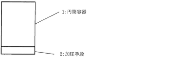
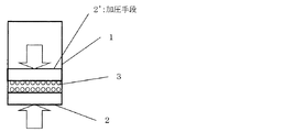
Niが被覆されたSi粒子の圧縮粉体の導電率の測定方法を図1〜3に示す。
図1に示すように、底部が加圧手段2となっているステンレス製の円筒容器1(直径1cm、高さ6cm)に、Niが被覆されたSi粒子の粉体(Niコートした粉末3)2gを入れ(図2)、円筒容器1の上部及び下部から加圧手段2,2’により圧力をかけつつ、2端子法によりNiコートした粉末3の抵抗を測定する(図3)。
Niコートした粉末3の抵抗値が一定になるまで加圧する。また、このときの圧縮粉体の厚みを測定する。
その上で、下記式(1)に従い、導電率を求めた。
式(1)
σ=L/(R・S)
σ:導電率(S/cm)
L:圧縮粉体の厚み(cm)
R:抵抗値(Ω)
S:円筒容器の断面積(cm2)
(2) Preparation of negative electrode material (Ni / Si) by electroless plating 0.070 g of nickel sulfate hexahydrate (Wako) was dissolved in 50 mL of 0.2 M sulfuric acid to prepare a plating solution. 0.140 g of silicon (Si) powder (Wako, theoretical capacity: 4200 mAh / g) passed through a sieve having an opening of 26 μm was put into the plating solution, and a rotor was put therein and stirred at 500 rpm with a magnetic stirrer at room temperature.
Sodium borohydride (Wako) 0.50 g which is a reducing agent was dissolved in 50 ml of pure water, this sodium borohydride aqueous solution was added to the above plating solution, and stirring was continued for 3 minutes.
After completion, suction filtration was performed, and the residue was washed with pure water. Ni / Si negative electrode material was prepared by vacuum drying at room temperature for 12 hours.
In addition, as a result of measuring the average particle diameter of the screened silicon powder with a laser diffraction type particle size distribution measuring apparatus (manufactured by Sysmex Corporation, model number: Mastersizer 2000), it was 13 μm.
For example, the electrical conductivity of the compressed powder of Si particles coated with Ni is 6.3 × 10 −5 S / cm.
A method for measuring the conductivity of the compressed powder of Si particles coated with Ni is shown in FIGS.
As shown in FIG. 1, a stainless steel cylindrical container 1 (diameter: 1 cm, height: 6 cm) whose bottom is a pressurizing means 2 is coated with Ni powder (Ni-coated powder 3). 2 g is added (FIG. 2), and the resistance of the Ni-coated
Pressurization is performed until the resistance value of the Ni-coated
Then, the electrical conductivity was determined according to the following formula (1).
Formula (1)
σ = L / (R ・ S)
σ: Conductivity (S / cm)
L: Compressed powder thickness (cm)
R: Resistance value (Ω)
S: Cross-sectional area of the cylindrical container (cm 2 )
(3)リチウムイオン電池の作製
(a)負極合材
負極材料(負極活物質)として、上記(2)で調製したNi/Si負極材料を用いた。この負極材料と上記(1)で調製した固体電解質を質量比70:30で混合しこれを負極層の材料(負極合材)とした。
(3) Production of lithium ion battery (a) Negative electrode composite The Ni / Si negative electrode material prepared in (2) above was used as the negative electrode material (negative electrode active material). This negative electrode material and the solid electrolyte prepared in the above (1) were mixed at a mass ratio of 70:30 to obtain a negative electrode layer material (negative electrode mixture).
(b)正極合材
硫黄(Aldrich、純度99.998%)0.500gと炭素(ライオン、ケッチェンブラック(KB)EC600JD)0.214gを乳鉢で混合した後、硫黄炭素の混合物を密閉性のステンレス容器に入れ、電気炉にて加熱処理した。加熱条件は室温から10℃/分にて150℃まで昇温し、150℃で6時間保持した後、300℃まで10℃/分で昇温し、2.75時間保持、その後自然冷却した。
得られた硫黄と炭素の複合体と上記(1)で調製した固体電解質粉末を、質量比50:50で混合し、遊星型ボールミル(フリッチュ製:型番P−7)でアルゴン中、室温(25℃)にて、回転速度を370rpmとし、5時間メカニカルミリング処理することで正極合材とした。
(B) Positive electrode mixture After mixing 0.500 g of sulfur (Aldrich, purity 99.998%) and 0.214 g of carbon (Lion, Ketjen Black (KB) EC600JD) in a mortar, the mixture of sulfur carbon was sealed. It put into the stainless steel container and heat-processed with the electric furnace. As heating conditions, the temperature was raised from room temperature to 150 ° C. at 10 ° C./minute, held at 150 ° C. for 6 hours, then heated to 300 ° C. at 10 ° C./minute, held for 2.75 hours, and then naturally cooled.
The obtained composite of sulfur and carbon and the solid electrolyte powder prepared in the above (1) were mixed at a mass ratio of 50:50, and a planetary ball mill (manufactured by Fritsch: Model No. P-7) was used at room temperature (25 C.), the rotational speed was 370 rpm, and a mechanical milling treatment was performed for 5 hours to obtain a positive electrode mixture.
(c)リチウムイオン電池
上記(1)で調製した固体電解質60mgを直径10mmのセラミック製の円筒に投入し、加圧成型して電解質層(電解質シート)とし、さらに上記で調整した正極合材を6.9mg投入し加圧成型した。正極合材とは反対側から上記負極合材5.0mg投入しさらに加圧成型した。リチウム源として、リチウム箔(本庄金属製)1.81mgを負極合材側に貼合し加圧成型することで、四層構造のリチウムイオン電池を作製した。
(C) Lithium ion battery 60 mg of the solid electrolyte prepared in the above (1) is put into a ceramic cylinder having a diameter of 10 mm, pressed to form an electrolyte layer (electrolyte sheet), and the positive electrode mixture prepared as described above. 6.9 mg was charged and pressure molded. 5.0 mg of the negative electrode mixture was introduced from the side opposite to the positive electrode mixture, and further pressure-molded. As a lithium source, 1.81 mg of lithium foil (manufactured by Honjo Metal Co., Ltd.) was bonded to the negative electrode composite material side and pressure-molded to produce a four-layer lithium ion battery.
実施例2
(1)無電解めっきによる負極材料(Ni−P/Si)の調製
0.2M硫酸(Wako)50mLに硫酸ニッケル六水和物(Wako)0.070gを溶解させ、さらに錯化剤であるクエン酸ナトリウム二水和物(Wako)0.014gを溶解させることにより、めっき液を調製した。
実施例1と同様に、目開き26μmのふるいにかけたSi粉末(Wako、平均粒子径:13μm)0.140gめっき液に投入し、回転子を入れ、マグネチックスターラーで500rpmの速度で撹拌しながら70℃まで加熱した。
リン源である次亜リン酸ナトリウム一水和物(Wako)0.05gを純水30mLに溶解させ、次亜リン酸ナトリウム水溶液を調製した。また、還元剤である水素化ホウ素ナトリウム(Wako)0.05gを、純水20mLに溶解させ、水素化ホウ素ナトリウム水溶液を調製した。次亜リン酸ナトリウム水溶液と水素化ホウ素ナトリウム水溶液をそれぞれ上記めっき液中に加え、70℃で1時間撹拌を続けた。
終了後、吸引ろ過し残留物を純水で洗浄し、常温で12時間真空乾燥して、Ni−P/Si負極材料を調製した。
例えば、Ni−Pが被覆されたSi粒子の圧縮粉体の導電率は6.3×10⁻⁷S/cmである。
尚、Ni−Pが被覆されたSi粒子の圧縮粉体の導電率の測定方法は、Niが被覆されたSi粒子の圧縮粉体の導電率の測定方法と同じである。
Example 2
(1) Preparation of negative electrode material (Ni-P / Si) by electroless plating 0.070 g of nickel sulfate hexahydrate (Wako) was dissolved in 50 mL of 0.2 M sulfuric acid (Wako), and further a quenching agent Quen A plating solution was prepared by dissolving 0.014 g of sodium acid dihydrate (Wako).
In the same manner as in Example 1, 0.140 g of Si powder (Wako, average particle size: 13 μm) passed through a sieve having an opening of 26 μm was added to a plating solution, a rotor was added, and the mixture was stirred with a magnetic stirrer at a speed of 500 rpm. Heated to 70 ° C.
A sodium hypophosphite aqueous solution was prepared by dissolving 0.05 g of sodium hypophosphite monohydrate (Wako) as a phosphorus source in 30 mL of pure water. Moreover, 0.05 g of sodium borohydride (Wako) which is a reducing agent was dissolved in 20 mL of pure water to prepare a sodium borohydride aqueous solution. A sodium hypophosphite aqueous solution and a sodium borohydride aqueous solution were added to the plating solution, respectively, and stirring was continued at 70 ° C. for 1 hour.
After completion, suction filtration was performed, the residue was washed with pure water, and vacuum dried at room temperature for 12 hours to prepare a Ni-P / Si negative electrode material.
For example, the electrical conductivity of the compressed powder of Si particles coated with Ni—P is 6.3 × 10 −7 S / cm.
The method of measuring the conductivity of the compressed powder of Si particles coated with Ni-P is the same as the method of measuring the conductivity of the compressed powder of Si particles coated with Ni.
(2)リチウムイオン電池の作製
正極合材は実施例1と同じものを用いた。
負極活物質として上記(1)で調製したNi−P/Si負極材料を用いた。この負極材料と実施例1と同じ固体電解質を質量比70:30で混合し、これを負極合材とした。
上記実施例1(1)で調製した固体電解質60mgを直径10mmのセラミック製の円筒に投入し、加圧成型して電解質層(電解質シート)とし、さらに上記正極合材を6.9mg投入し加圧成型した。正極合材とは反対側から上記(1)で調製した負極合材4.3mg投入しさらに加圧成型した。リチウム源として、リチウム箔(本庄金属製)2.1gを負極合材側に貼合し加圧成型することで、四層構造のリチウムイオン電池を作製した。
(2) Production of Lithium Ion Battery The same positive electrode composite as in Example 1 was used.
The Ni—P / Si negative electrode material prepared in (1) above was used as the negative electrode active material. This negative electrode material and the same solid electrolyte as in Example 1 were mixed at a mass ratio of 70:30, and this was used as a negative electrode mixture.
60 mg of the solid electrolyte prepared in Example 1 (1) above was put into a ceramic cylinder having a diameter of 10 mm, pressed to form an electrolyte layer (electrolyte sheet), and 6.9 mg of the above positive electrode mixture was added and added. Press molded. 4.3 mg of the negative electrode mixture prepared in the above (1) was charged from the side opposite to the positive electrode mixture, and further pressure-molded. As a lithium source, 2.1 g of lithium foil (manufactured by Honjo Metal) was bonded to the negative electrode mixture side and pressure-molded to produce a lithium ion battery having a four-layer structure.
比較例1
・リチウムイオン電池の作製
正極合材は実施例1と同じものを用いた。
負極活物質として目開き26μmのふるいにかけたSi粉末を用いた。この負極活物質と上記実施例1(1)で調製した固体電解質を質量比70:30で混合しこれを負極合材とした。
上記実施例1(1)で調製した固体電解質60mgを直径10mmのセラミック製の円筒に投入し、加圧成型して電解質層(電解質シート)とし、さらに上記で調製した正極合材を6.9mg投入し加圧成型した。正極合材とは反対側から上記負極合材4.3mg投入しさらに加圧成型した。リチウム源として、リチウム箔(本庄金属製)2.1gを負極合材側に貼合し加圧成型することで、四層構造のリチウムイオン電池を作製した。
Comparative Example 1
-Production of Lithium Ion Battery The same positive electrode mixture as in Example 1 was used.
As a negative electrode active material, Si powder applied to a sieve having an aperture of 26 μm was used. This negative electrode active material and the solid electrolyte prepared in Example 1 (1) were mixed at a mass ratio of 70:30 to obtain a negative electrode mixture.
60 mg of the solid electrolyte prepared in Example 1 (1) above was put into a ceramic cylinder having a diameter of 10 mm, pressed to form an electrolyte layer (electrolyte sheet), and 6.9 mg of the positive electrode mixture prepared above. Input and pressure molding. 4.3 mg of the negative electrode mixture was charged from the side opposite to the positive electrode mixture, and further pressure-molded. As a lithium source, 2.1 g of lithium foil (manufactured by Honjo Metal) was bonded to the negative electrode mixture side and pressure-molded to produce a lithium ion battery having a four-layer structure.
上記各例で作製したリチウムイオン電池について、放電容量及び可逆効率を評価した。
具体的に、リチウムイオン電池を充放電速度0.1Cで電圧が0.6Vになるまで放電し、その後、0.2Cで2.65Vまで定電流(CC)充電し、その電圧で電流が50.93μA/cm2となるまで定電圧(CV)充電した。このときの負極活物質当りの充電容量Q1(mAh/g)を求めた。引き続き、0.2Cで電圧が0.6Vになるまで放電し、負極活物質当りの放電容量Q2(mAh/g)を求めた。この充放電容量より可逆効率Q2/Q1を算出した。
表1に充電容量Q1、放電容量Q2、可逆効率Q2/Q1を示す。
About the lithium ion battery produced in each said example, discharge capacity and reversible efficiency were evaluated.
Specifically, the lithium ion battery is discharged at a charge / discharge rate of 0.1 C until the voltage reaches 0.6 V, and then charged at a constant current (CC) of 2.65 V at 0.2 C, and the current is 50 at that voltage. The battery was charged at a constant voltage (CV) until it reached 93 μA / cm 2 . The charge capacity Q1 (mAh / g) per negative electrode active material at this time was determined. Subsequently, the battery was discharged at 0.2 C until the voltage became 0.6 V, and the discharge capacity Q2 (mAh / g) per negative electrode active material was determined. The reversible efficiency Q2 / Q1 was calculated from this charge / discharge capacity.
Table 1 shows the charge capacity Q1, the discharge capacity Q2, and the reversible efficiency Q2 / Q1.

表1の結果から、実施例1及び2は可逆効率が高く、効率的な充電が可能である一方、比較例1では可逆効率が低く、充電は極めて非効率的であることが確認できた。 From the results of Table 1, it was confirmed that Examples 1 and 2 had high reversible efficiency and could be efficiently charged, while Comparative Example 1 had low reversible efficiency and was extremely inefficient.
本発明のリチウムイオン電池は、携帯情報端末、携帯電子機器、家庭用小型電力貯蔵装置、モーターを電力源とする自動二輪車、電気自動車、ハイブリッド電気自動車等の電池として用いることができる。 The lithium ion battery of the present invention can be used as a battery for a portable information terminal, a portable electronic device, a small electric power storage device for home use, a motorcycle using a motor as a power source, an electric vehicle, a hybrid electric vehicle, or the like.
1 円筒容器
2 加圧手段
3 NiコートしたSi粉末
1
Claims (9)
前記負極層は、負極材料と固体電解質とを含み、
前記負極材料は、リチウムイオン電池用負極活物質粒子とこのリチウムイオン電池用負極活物質粒子表面に付着した導電性物質とを有し、
前記リチウムイオン電池用負極活物質粒子は、理論容量が800mAh/g以上であり、
前記導電性物質は、1×10³S/cm以上の導電率を有し、
前記電解質層は、無機固体電解質を含む
ことを特徴とするリチウムイオン電池。 A lithium ion battery having a negative electrode layer, an electrolyte layer, and a positive electrode layer,
The negative electrode layer includes a negative electrode material and a solid electrolyte,
The negative electrode material has negative electrode active material particles for lithium ion batteries and a conductive material attached to the surface of the negative electrode active material particles for lithium ion batteries,
The negative electrode active material particles for lithium ion batteries have a theoretical capacity of 800 mAh / g or more,
The conductive material has a conductivity of 1 × 10 3 S / cm or more,
The lithium ion battery, wherein the electrolyte layer includes an inorganic solid electrolyte.
前記負極層は、負極材料と固体電解質とを含み、
前記負極材料は、リチウムイオン電池用負極活物質粒子とこのリチウムイオン電池用負極活物質粒子表面に付着した導電性物質とを有し、
前記リチウムイオン電池用負極活物質粒子は、理論容量が800mAh/g以上であり、
前記導電性物質は、ニッケル、銅、アルミニウム、インジウム、銀、コバルト、マグネシウム、リチウム、クロム、金、ルテニウム、白金、ベリリウム、イリジウム、モリブデン、ニオブ、オスニウム、ロジウム、タングステン、亜鉛のうち、少なくとも1つを構成元素とし、
前記電解質層は、無機固体電解質を含む
ことを特徴とするリチウムイオン電池。 A lithium ion battery having a negative electrode layer, an electrolyte layer, and a positive electrode layer,
The negative electrode layer includes a negative electrode material and a solid electrolyte,
The negative electrode material has negative electrode active material particles for lithium ion batteries and a conductive material attached to the surface of the negative electrode active material particles for lithium ion batteries,
The negative electrode active material particles for lithium ion batteries have a theoretical capacity of 800 mAh / g or more,
The conductive material is at least one of nickel, copper, aluminum, indium, silver, cobalt, magnesium, lithium, chromium, gold, ruthenium, platinum, beryllium, iridium, molybdenum, niobium, osmium, rhodium, tungsten, and zinc. One element,
The lithium ion battery, wherein the electrolyte layer includes an inorganic solid electrolyte.
前記負極層は、負極材料と固体電解質とを含み、
前記負極材料は、リチウムイオン電池用負極活物質粒子とこのリチウムイオン電池用負極活物質粒子表面に付着した導電性物質とを有し、
前記リチウムイオン電池用負極活物質粒子は、理論容量が800mAh/g以上であり、
前記負極材料の圧縮粉体は、1.0×10⁻⁷S/cm以上の導電率を有し、
前記電解質層は、無機固体電解質を含む
ことを特徴とするリチウムイオン電池。 A lithium ion battery having a negative electrode layer, an electrolyte layer, and a positive electrode layer,
The negative electrode layer includes a negative electrode material and a solid electrolyte,
The negative electrode material has negative electrode active material particles for lithium ion batteries and a conductive material attached to the surface of the negative electrode active material particles for lithium ion batteries,
The negative electrode active material particles for lithium ion batteries have a theoretical capacity of 800 mAh / g or more,
The compressed powder of the negative electrode material has a conductivity of 1.0 × 10 −7 S / cm or more,
The lithium ion battery, wherein the electrolyte layer includes an inorganic solid electrolyte.
The lithium according to any one of claims 1 to 8, wherein the negative electrode material is obtained by electroless plating the negative electrode active material particles for a lithium ion battery in a plating bath containing ions of the conductive substance. Ion battery.
Priority Applications (1)
| Application Number | Priority Date | Filing Date | Title |
|---|---|---|---|
| JP2011003623A JP2012146479A (en) | 2011-01-12 | 2011-01-12 | Lithium ion battery |
Applications Claiming Priority (1)
| Application Number | Priority Date | Filing Date | Title |
|---|---|---|---|
| JP2011003623A JP2012146479A (en) | 2011-01-12 | 2011-01-12 | Lithium ion battery |
Publications (1)
| Publication Number | Publication Date |
|---|---|
| JP2012146479A true JP2012146479A (en) | 2012-08-02 |
Family
ID=46789879
Family Applications (1)
| Application Number | Title | Priority Date | Filing Date |
|---|---|---|---|
| JP2011003623A Pending JP2012146479A (en) | 2011-01-12 | 2011-01-12 | Lithium ion battery |
Country Status (1)
| Country | Link |
|---|---|
| JP (1) | JP2012146479A (en) |
Cited By (11)
| Publication number | Priority date | Publication date | Assignee | Title |
|---|---|---|---|---|
| WO2014058683A1 (en) * | 2012-10-09 | 2014-04-17 | Microsoft Corporation | Solid-state battery electrodes |
| JP2014086218A (en) * | 2012-10-22 | 2014-05-12 | Toyota Motor Corp | All solid battery system |
| KR101927414B1 (en) | 2018-10-19 | 2018-12-10 | 삼성전자주식회사 | Electro active material for secondary battery, conductive composition for secondary battery, cathode material, cathode structure and secondary battery comprising the same, and fabricating methods thereof |
| US10333123B2 (en) | 2012-03-01 | 2019-06-25 | Johnson Ip Holding, Llc | High capacity solid state composite cathode, solid state composite separator, solid-state rechargeable lithium battery and methods of making same |
| WO2019123981A1 (en) * | 2017-12-22 | 2019-06-27 | 昭和電工株式会社 | Method of manufacturing lithium ion secondary battery |
| WO2019123951A1 (en) * | 2017-12-22 | 2019-06-27 | 昭和電工株式会社 | Lithium-ion secondary cell |
| US10566611B2 (en) | 2015-12-21 | 2020-02-18 | Johnson Ip Holding, Llc | Solid-state batteries, separators, electrodes, and methods of fabrication |
| US10586978B2 (en) | 2012-12-27 | 2020-03-10 | Samsung Electronics Co., Ltd | Negative electrode active material for secondary battery, conductive composition for secondary battery, negative electrode material comprising same, negative electrode structure and secondary battery comprising same, and method for manufacturing same |
| WO2020088965A1 (en) * | 2018-10-31 | 2020-05-07 | Robert Bosch Gmbh | Electrode, battery cell and use thereof |
| CN111710915A (en) * | 2020-06-28 | 2020-09-25 | 宜春清陶能源科技有限公司 | Solid-state lithium ion battery |
| USRE49205E1 (en) | 2016-01-22 | 2022-09-06 | Johnson Ip Holding, Llc | Johnson lithium oxygen electrochemical engine |
Citations (5)
| Publication number | Priority date | Publication date | Assignee | Title |
|---|---|---|---|---|
| JP2000173587A (en) * | 1998-12-02 | 2000-06-23 | Matsushita Electric Ind Co Ltd | Non-aqueous electrolyte secondary battery |
| JP2006092808A (en) * | 2004-09-21 | 2006-04-06 | Nissan Motor Co Ltd | Battery structure |
| JP2009093968A (en) * | 2007-10-10 | 2009-04-30 | Seiko Epson Corp | Whole-solid lithium secondary battery |
| JP2010040218A (en) * | 2008-07-31 | 2010-02-18 | Idemitsu Kosan Co Ltd | Electrode material sheet for lithium battery, solid lithium battery, and device with the solid lithium battery |
| JP2011165410A (en) * | 2010-02-05 | 2011-08-25 | Ohara Inc | All solid lithium ion secondary battery and method for manufacturing the same |
-
2011
- 2011-01-12 JP JP2011003623A patent/JP2012146479A/en active Pending
Patent Citations (5)
| Publication number | Priority date | Publication date | Assignee | Title |
|---|---|---|---|---|
| JP2000173587A (en) * | 1998-12-02 | 2000-06-23 | Matsushita Electric Ind Co Ltd | Non-aqueous electrolyte secondary battery |
| JP2006092808A (en) * | 2004-09-21 | 2006-04-06 | Nissan Motor Co Ltd | Battery structure |
| JP2009093968A (en) * | 2007-10-10 | 2009-04-30 | Seiko Epson Corp | Whole-solid lithium secondary battery |
| JP2010040218A (en) * | 2008-07-31 | 2010-02-18 | Idemitsu Kosan Co Ltd | Electrode material sheet for lithium battery, solid lithium battery, and device with the solid lithium battery |
| JP2011165410A (en) * | 2010-02-05 | 2011-08-25 | Ohara Inc | All solid lithium ion secondary battery and method for manufacturing the same |
Cited By (15)
| Publication number | Priority date | Publication date | Assignee | Title |
|---|---|---|---|---|
| US10333123B2 (en) | 2012-03-01 | 2019-06-25 | Johnson Ip Holding, Llc | High capacity solid state composite cathode, solid state composite separator, solid-state rechargeable lithium battery and methods of making same |
| US9793525B2 (en) | 2012-10-09 | 2017-10-17 | Johnson Battery Technologies, Inc. | Solid-state battery electrodes |
| US10084168B2 (en) | 2012-10-09 | 2018-09-25 | Johnson Battery Technologies, Inc. | Solid-state battery separators and methods of fabrication |
| WO2014058683A1 (en) * | 2012-10-09 | 2014-04-17 | Microsoft Corporation | Solid-state battery electrodes |
| JP2014086218A (en) * | 2012-10-22 | 2014-05-12 | Toyota Motor Corp | All solid battery system |
| US10586978B2 (en) | 2012-12-27 | 2020-03-10 | Samsung Electronics Co., Ltd | Negative electrode active material for secondary battery, conductive composition for secondary battery, negative electrode material comprising same, negative electrode structure and secondary battery comprising same, and method for manufacturing same |
| US10566611B2 (en) | 2015-12-21 | 2020-02-18 | Johnson Ip Holding, Llc | Solid-state batteries, separators, electrodes, and methods of fabrication |
| US11417873B2 (en) | 2015-12-21 | 2022-08-16 | Johnson Ip Holding, Llc | Solid-state batteries, separators, electrodes, and methods of fabrication |
| USRE49205E1 (en) | 2016-01-22 | 2022-09-06 | Johnson Ip Holding, Llc | Johnson lithium oxygen electrochemical engine |
| WO2019123981A1 (en) * | 2017-12-22 | 2019-06-27 | 昭和電工株式会社 | Method of manufacturing lithium ion secondary battery |
| WO2019123951A1 (en) * | 2017-12-22 | 2019-06-27 | 昭和電工株式会社 | Lithium-ion secondary cell |
| KR101927414B1 (en) | 2018-10-19 | 2018-12-10 | 삼성전자주식회사 | Electro active material for secondary battery, conductive composition for secondary battery, cathode material, cathode structure and secondary battery comprising the same, and fabricating methods thereof |
| WO2020088965A1 (en) * | 2018-10-31 | 2020-05-07 | Robert Bosch Gmbh | Electrode, battery cell and use thereof |
| CN111710915A (en) * | 2020-06-28 | 2020-09-25 | 宜春清陶能源科技有限公司 | Solid-state lithium ion battery |
| CN111710915B (en) * | 2020-06-28 | 2022-12-16 | 宜春清陶能源科技有限公司 | Solid-state lithium ion battery |
Similar Documents
| Publication | Publication Date | Title |
|---|---|---|
| US20240047761A1 (en) | All-solid-state secondary battery and method of charging the same | |
| JP2012146479A (en) | Lithium ion battery | |
| JP7063653B2 (en) | All-solid-state secondary battery | |
| CN105406033B (en) | Anode mixture, positive pole, solid state battery and their manufacture method | |
| JP7028354B2 (en) | All-solid-state lithium-ion secondary battery | |
| JP6952467B2 (en) | Positive active material for all-solid-state secondary batteries, positive-positive active material layer for all-solid-state secondary batteries, and all-solid-state secondary batteries | |
| CN105938894B (en) | The manufacturing method of electrode body | |
| WO2015068268A1 (en) | All-solid-state cell, electrode for all-solid-state cell, and method for manufacturing same | |
| US11682791B2 (en) | Solid electrolyte, electrochemical battery including the solid electrolyte, and method of preparing the solid electrolyte | |
| JP5682318B2 (en) | All solid battery | |
| CN104106164A (en) | Secondary cell, method for manufacturing secondary cell, electrode for secondary cell, and electronic device | |
| JP6927292B2 (en) | All-solid-state lithium-ion secondary battery | |
| JP2011065887A (en) | Positive electrode material, method for manufacturing the same, and lithium ion battery | |
| JP5747848B2 (en) | Method for producing positive electrode active material layer-containing body | |
| JP7321769B2 (en) | All-solid lithium secondary battery | |
| US20230275261A1 (en) | All-solid-state secondary battery and manufacturing method therefor | |
| JP2012243645A (en) | Electrode and all-solid state nonaqueous electrolyte battery | |
| JP2021051866A (en) | All-solid battery | |
| KR20210133085A (en) | All-solid-state secondary battery | |
| WO2013069083A1 (en) | All-solid-state battery | |
| JP6576033B2 (en) | Lithium ion secondary battery and method for producing positive electrode active material for lithium ion secondary battery | |
| JP2014123559A (en) | Cathode active material for lithium ion secondary battery and method of manufacturing the same | |
| JP2019117768A (en) | All-solid secondary battery | |
| JP2016081905A (en) | Solid electrolyte layer | |
| JP2022521178A (en) | Manufacturing method of positive electrode of all-solid-state battery and positive electrode of all-solid-state battery manufactured by this method |
Legal Events
| Date | Code | Title | Description |
|---|---|---|---|
| A521 | Written amendment |
Free format text: JAPANESE INTERMEDIATE CODE: A523 Effective date: 20130111 |
|
| A621 | Written request for application examination |
Free format text: JAPANESE INTERMEDIATE CODE: A621 Effective date: 20131224 |
|
| A521 | Written amendment |
Free format text: JAPANESE INTERMEDIATE CODE: A821 Effective date: 20131224 |
|
| A977 | Report on retrieval |
Free format text: JAPANESE INTERMEDIATE CODE: A971007 Effective date: 20140430 |
|
| A131 | Notification of reasons for refusal |
Free format text: JAPANESE INTERMEDIATE CODE: A131 Effective date: 20140507 |
|
| A521 | Written amendment |
Free format text: JAPANESE INTERMEDIATE CODE: A523 Effective date: 20140703 |
|
| A131 | Notification of reasons for refusal |
Free format text: JAPANESE INTERMEDIATE CODE: A131 Effective date: 20150303 |
|
| A521 | Written amendment |
Free format text: JAPANESE INTERMEDIATE CODE: A523 Effective date: 20150501 |
|
| A02 | Decision of refusal |
Free format text: JAPANESE INTERMEDIATE CODE: A02 Effective date: 20151117 |